1
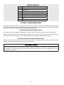
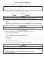
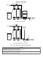
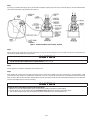
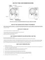
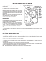
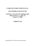
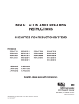
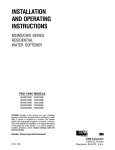
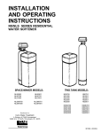
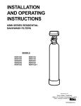
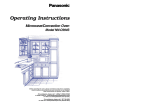
INSTALLATION AND OPERATING
INSTRUCTIONS
CS/CSM SERIES RESIDENTIAL
WATER SOFTENERS
MODELS:
CS1001
CS1501
CS2001
CSM1001
CSM1501
CSM2001
Installer, please leave with homeowner.
Homeowner, retain for future reference.
INSTR2201 0312
SAFETY INFORMATION
Read, understand, and follow all safety information contained in these instructions prior to installation and use of the Aqua-Pure® CS/CSM Series Residential Water Softener. Retain these instructions for future reference. Failure to follow installation, operation and maintenance instructions may result in
property damage and will void warranty.
Intended use:
The Aqua-Pure CS/CSM Series Residential Water Softeners are intended for use in softening water in homes and have not been evaluated for other uses.
These systems must be installed indoors near the point of entry of a home water line, and be installed by qualified professional installers according to these
installation instructions.
EXPLANATION OF SIGNAL WORD CONSEQUENCES
WARNING
CAUTION
CAUTION
Indicates a potentially hazardous situation, which, if not avoided, could result in death or serious injury and/or property damage.
Indicates a potentially hazardous situation, which, if not avoided, may result in minor or moderate injury and/or property damage.
Indicates a potentially hazardous situation, which, if not avoided, may result in property damage.
WARNING
To reduce the risk associated with choking:
• Do not allow children under 3 years of age to have access to small parts during the installation of this product.
To reduce the risk associated with ingestion of contaminants:
• Do not use with water that is microbiologically unsafe or of unknown quality without adequate disinfection before or after the system.
To reduce the risk of physical injury:
• Shut off inlet water supply and depressurize system as shown in manual prior to service.
To reduce the risk associated with a hazardous voltage:
• If the home electrical system requires use of the cold water system as an electrical safety ground, a jumper must be used to ensure a sufficient ground connection across
the water softener installation piping — refer installation to qualified personnel.
• Do not use the system if the power cord is damaged — contact qualified service personnel for repair.
To reduce the risk associated with back strain due to the heavy weight of the various system components:
• Follow safe lifting procedures.
CAUTION
To reduce the risk associated skin, eye, and respiratory tract irritation from gravel and filter media during installation:
• Gravel and several types of filter media may be used in this product, depending upon the application. During installation, dust may cause irritation to skin, eyes, and
respiratory tract.
• Utilize a NIOSH-approved dust filter mask, protective gloves, and appropriate eye protection when handling and pouring gravel and filter media.
• To request an MSDS relating to this product, call 203-238-8965 or go to www.3M.com, select country, and use the search engine to search MSDS. For emergencies, call 800-364-3577 or 651-737-6501 (24 hours).
CAUTION
To reduce the risk associated with property damage due to water leakage:
• Read and follow Use instructions before installation and use of this water treatment system.
• Installation and use MUST comply with existing state or local plumbing codes.
• Protect from freezing, relieve pressure and drain system when temperatures are expected to drop below 40°F (4°C).
• Do not install on hot water supply lines. The maximum operating water temperature of this water softener is 110°F (43.3°C).
• Do not install if water pressure exceeds 125 psi. If your water pressure exceeds 80 psi (552 kPa), you must install a pressure limiting valve. Contact a plumbing
professional if you are uncertain how to check your water pressure.
• Do not install where water hammer conditions may occur. If water hammer conditions exist you must install a water hammer arrester. Contact a plumbing professional if you are uncertain how to check for this condition.
• Where a backflow prevention device is installed on a water system, a device for controlling pressure due to thermal expansion must be installed.
• Do not use a torch or other high temperature sources near system.
• On plastic fittings, never use pipe sealant or pipe dope. Use PTFE thread tape only, pipe dope properties may deteriorate plastic.
• Take care when using pliers or pipe wrenches to tighten plastic fittings, as damage may occur if over tightening occurs.
• Do not install in direct sunlight or outdoors.
• Install system in such a position as to prevent it from being struck by other items used in the area of installation.
• Ensure all tubing and fittings are secure and free of leaks.
• SHUT OFF FUEL OR ELECTRIC POWER SUPPLY TO WATER HEATER after water is shut off.
• Do not install system where water lines could be subjected to vacuum conditions without appropriate measures for vacuum prevention.
• Do not apply heat to any fitting connected to bypass or control valve as damage may result to internal parts or connecting adapters.
• Install on a flat/level surface. It is also advisable to sweep the floor to eliminate objects that could pierce the brine tank.
To reduce the risk associated with property damage due to plugged water lines:
• Pay particular attention to correct orientation of control valve. Water flow should match arrow on control valve. The Inlet and Outlet of other water treatment
equipment products will vary depending on the control valve brand used.
IMPORTANT NOTES
• Failure to follow instructions will void warranty.
TABLE OF CONTENTS
SECTION
DESCRIPTION
1
BEFORE INSTALLATION
2
INSTALLATION
3
REGENERATION INSTRUCTIONS
4
MAINTENANCE
5
SERVICE INSTRUCTIONS
6
SPECIFICATIONS & OPERATING DATA
7
PARTS
8
LIMITED WARRANTY
SECTION 1: BEFORE INSTALLATION
Congratulations! We believe your purchase of this water softener will prove to be a very wise choice. When properly installed, operated, and maintained,
your new water softener will provide years of dependable service. Before starting the installation, please read this entire manual for an overview, and then
follow the installation instructions. Failure to follow the instructions will void the warranty.
Inspecting And Handling Your Water Softener:
Inspect shipping carton and the equipment for shipping damage. If damaged, notify the transportation company and request a damage inspection.
Handle the equipment with care. Damage can result if dropped or if the brine tank is set on sharp, uneven projections on the floor. When handling, do not
turn the water softener unit upside down or on its side to help prevent media from entering valve and being discharged downstream.
Make Sure Your Water Has Been Thoroughly Tested:
An analysis of your water should be made prior to the selection of your water softener. You can typically get this service through your place of purchase,
which may require sending a sample to the factory for analysis and recommendations.
IMPORTANT NOTES
Water softeners are designed to reduce hardness and reasonable amounts of soluble iron if consideration is given to iron content when selecting
model and regeneration settings. To treat sulfur (hydrogen sulfide), bacterial iron, precipitated iron or very high levels of soluble iron special equipment in addition to a water softener is required. For best results, the Aqua-Pure® APPM or APIF Series Systems are recommended for use on waters
containing more than 2 ppm of iron.
1-1
Check Your Pumping Rate and Water Pressure:
Two water system conditions must be checked carefully to avoid unsatisfactory operation or equipment damage:
1) MINIMUM water pressure required at the water softener inlet is 20 psi (138 kPa).
CAUTION
To reduce the risk associated with property damage due to water leakage:
• Do not install if water pressure exceeds 125 psi. If your water pressure exceeds 80 psi (552 kPa), you must install a pressure limiting valve. Contact a plumbing professional if you are uncertain how to check your water pressure.
NOTE: Call your local water department or plant operator to obtain pressure readings. If you have a private well, the gauge on the pressure tank
will indicate the high and low system pressure. Record your water pressure data below:
Water Pressure:
Low
psi
High
psi
CAUTION
To reduce the risk associated with property damage due to water leakage:
• Do not install system where water lines could be subjected to vacuum conditions without appropriate measures for vacuum prevention.
The installer is required to take appropriate measures if there is the possibility a vacuum condition may occur. This would include the installation
of an appropriate device in the supply line to the system, i.e., a vacuum breaker or backflow prevention device. Vacuum damage voids the factory
warranty.
2) The pumping rate of your well must be sufficient for satisfactory operation and BACKWASHING of the water softener. (See Specifications And
Operating Data, Section 6).
IMPORTANT NOTE
If sediment is present, the installation of a sediment pre-filter is recommended. Even if sediment is not currently present or at a level high enough to be
objectionable, a pre-filter can help increase the efficiency of the softener and help reduce the amount of maintenance required.
Installation Site Selection:
Select the location of your water softener with care. Various conditions which contribute to proper location are as follows:
1) Locate as close as possible to water supply source.
2) Locate as close as possible to a drain.
3) Locate in correct relationship to other water conditioning equipment (Figure 1, page 2-1).
4) Locate the water softener in the supply line BEFORE the water heater. Temperatures above 110°F (43°C) will damage the water softener and void
the factory warranty.
5) DO NOT install the water softener in a location where freezing temperatures occur. Freezing may cause permanent damage and will also void
the factory warranty.
6) Allow sufficient space around the installation for easy servicing.
7) Provide a non-switched 110V, 60Hz (220V, 50Hz for specified systems) power source for the control valve.
WARNING
To reduce the risk associated with ingestion of contaminants:
• Do not use with water that is microbiologically unsafe or of unknown quality without adequate disinfection before or after the system.
CAUTION
To reduce the risk associated with property damage due to water leakage:
• Protect from freezing, relieve pressure and drain system when temperatures are expected to drop below 40°F (4°C).
• Do not install on hot water supply lines. The maximum operating water temperature of this water softener is 110°F (43.3°C).
• Do not install in direct sunlight or outdoors.
1-2
Facts to Remember While Planning The Installation:
1) All installation procedures MUST conform to local and state plumbing codes.
2) If lawn sprinklers, a swimming pool, or geothermal heating/cooling or water for other devices/activities are to be treated by the water softener, a
larger model MUST be selected to accommodate the higher flow rate plus the backwashing requirements of the water softener. Consult your Dealer/
Installer or our Customer Service Department at 1-800-222-7880 for alternative instructions if the pumping rate is insufficient.
3) Remember that the water softener INLET is attached to the pipe that supplies water (i.e. delivers water from the well pump or after the water
meter) and the OUTLET is the line that runs toward the water heater.
CAUTION
To reduce the risk associated with property damage due to plugged water lines:
• Pay particular attention to correct orientation of control valve. Water flow should match arrow on control valve. The Inlet and Outlet of other water treatment
equipment products will vary depending on the control valve brand used.
4) Before beginning the installation review the existing piping system and to determine the size, number and type of fittings required.
WARNING
To reduce the risk associated with a hazardous voltage:
• If the home electrical system requires use of the cold water system as an electrical safety ground, a jumper must be used to ensure a sufficient ground connection
across the water softener installation piping — refer installation to qualified personnel.
5) Sweep the floor to eliminate objects that could pierce the brine tank.
IMPORTANT NOTE
SODIUM INFORMATION: Water softeners using sodium chloride for regeneration add sodium to the water. People who are on sodium restricted diets
should consider the added sodium as part of their overall sodium intake.
1-3
SECTION 2: INSTALLATION
TREATED WATER
WASTE DRAIN
WASTE DRAIN
TREATED
SOFT WATER
PRESSURE
TANK
BRINE
TANK
RAW
WELL
WATER
WATER
SOFTENER
BACKWASH
FILTER
PRESSURE
SWITCH.
CHECK VALVE
TYPICAL WELL INSTALLATION
TREATED WATER
TREATED
SOFT WATER
WASTE DRAIN
WASTE DRAIN
WATER FOR
LAWN SPRINKLERS
OR OTHER
HIGH DEMAND
METER
BRINE
TANK
RAW
WATER
WATER
SOFTENER
BACKWASH
FILTER
CHECK VALVE
TYPICAL PUBLIC WATER SUPPLY INSTALLATION
Figure 1. Typical Installation Sequence Of Water Conditioning Equipment
CAUTION
To reduce the risk associated with property damage due to water leakage:
• Read and follow Use instructions before installation and use of this water treatment system.
• Installation and use MUST comply with existing state or local plumbing codes.
To reduce the risk associated with property damage due to plugged water lines:
• Pay particular attention to correct orientation of control valve. Water flow should match arrow on control valve. The Inlet and Outlet of other water treatment
equipment products will vary depending on the control valve brand used.
2-1
Step 1
If not factory pre-installed, attach bypass valve or yoke assembly using adapter couplings, clips and screws to control valve (Figure 2). On meter initiated models,
attach meter between bypass valve and control valve (Figure 2).
Figure 2. Softener And Brine Tank Assembly, Top View
Step 2
Shut off all water at main supply valve. On a private well system, turn off power to pump and drain pressure tank. Make certain pressure is relieved from complete system by opening nearest faucet to drain system.
CAUTION
To reduce the risk associated with property damage due to water leakage:
• SHUT OFF FUEL OR ELECTRIC POWER SUPPLY TO WATER HEATER after water is shut off.
Step 3
Cut main supply line as required to fit plumbing to inlet and outlet of unit.
Step 4
Attach plumbing. Do not apply heat to any fitting connected to bypass or control valve as damage may result to internal parts or connecting adapters. Make
certain water flow enters through inlet and discharges through outlet. Loosen set screw and pull out drain line flow control (DLFC) assembly from valve body
(Figure 2). Unscrew drain line elbow from DLFC. Apply thread tape to threads. Reassemble and fully insert into valve body before tightening set screw with finger
pressure only (overtightening set screw may crack fitting).
CAUTION
To reduce the risk associated with property damage due to water leakage:
• Do not use a torch or other high temperature sources near filter system, cartridges, plastic fittings or plastic plumbing.
• On plastic fittings, never use pipe sealant or pipe dope. Use PTFE thread tape only, pipe dope properties may deteriorate plastic.
• Take care when using pliers or pipe wrenches to tighten plastic fittings, as damage may occur if over tightening occurs.
2-2
Step 5
Attach drain line to drain line fitting. To prevent back pressure from reducing flow rate below minimum
required for backwash, drain line must be sized according to run length and relative height. Be careful not to
bend flexible drain tubing sharply enough to cause "kinking" (if kinking occurs drain line must be replaced).
Typical examples of proper drain line diameters are:
EQUIPMENT
DRAIN LINE
AIR GAP
2" REF.
(1) 1/2 in. ID up to 15 ft. when discharge is lower than inlet.
DRAIN
(2) 5/8 in. ID up to 15 ft. when discharge is slightly higher than inlet.
(3) 3/4 in. ID when drain is 25 ft. away and/or drain is installed overhead.
Some areas prohibit the use of flexible drain lines. Check with local code officials prior to installation.
Step 6
Position drain line over drain and secure firmly. To prevent backsiphoning of waste water, provide an air gap
of at least 2 in. or 2 pipe diameters between end of drain hose and drain (Figure 3). DO NOT raise drain line
more than 10 ft. above floor.
Figure 3. Typical Drain
Step 7
Connect one end of the 3/8 in. poly line to brine valve located on the right side of control valve. Connect other end to elbow inside of brine well. Brass insert
sleeves and plastic ferrules must be used where necessary. (Figure 2 and Control Valve Parts drawing, Section 7).
Step 8
Install overflow line to brine tank overflow fitting (Figure 2). Discharge of line must be lower than overflow fitting. DO NOT INTERCONNECT OVERFLOW LINE
WITH VALVE DRAIN LINE.
Step 9
Make certain bypass valve inlet and outlet knobs are in "BYPASS" position. After all plumbing connections have been completed, open main water shut-off valve
or restore power to well pump. Check for leaks and correct as necessary.
Step 10
Plug control valve power cord into 110v/60hz, non-switched power source. Manually
stage control to backwash position (See "How To Manually Regenerate Your Water Softener At Any Time") and then unplug power cord to prevent the unit from advancing
automatically.
ROTATE
KNOBS
Step 11
Partially open inlet valve in plumbing or on bypass valve (Figure 4). This will allow the
unit to fill slowly from the bottom up, eliminating air entrapment. Allow unit to fill slowly,
failure to do so could result in loss of resin to the drain. Once a steady stream of water,
no air, is flowing to drain, the inlet valve can be fully opened. The outlet valve can also
be opened and the bypass (if applicable) can be closed.
SERVICE
BYPASS
Figure 4. Bypass Valve
Step 12
On time clock initiated models, set regeneration frequency. Refer to Regeneration Frequency Schedules (Section 3) to determine correct frequency, then refer to
How To Set Time Clock Regeneration Control (Section 3) for instructions on setting frequency. For meter initiated models, refer to How To Set Meter Regeneration
Control.
NOTE: Regeneration settings for both time clock and meter initiated models are factory preset for the most efficient salt use and minimum water consumption
used for regeneration (as little as 30 gallons), and conform to the industry salt efficiency standards (required by some states). Regeneration frequency schedules
are designed for use with factory regeneration settings (listed in Specifications And Operating Data, Section 6).
The control valve design permits adjustment of the salt dosage. This adjustment may be necessary when unusual operating conditions exist, such as high concentrations of iron or hardness and/or high flow rates or daily water consumption (refer to "How To Set Regeneration Cycle Program" Section 3) for adjustment
procedures.
NOTE: For salt dosages greater than 15 lbs (6.8 kg), grid leg extensions must be attached to bottom of grid legs. For salt dosages less than 15 lbs (6.8 kg). DO
NOT use extension legs.
2-3
Step 13
Set time of day (refer to appropriate How To Set Time Clock/Meter Regeneration Control, Section 3). When shifting to daylight saving time (and back), you may
wish to adjust time of day accordingly.
NOTE: time of regeneration is preset for 2:00 a.m. because at this time water consumption is generally minimal (a built-in hard water bypass does, however,
permit water to be drawn during regeneration). Should your life style require regular use of water during the 2:00 to 3:00 a.m. regeneration period, or if other
water treatment equipment is also set for 2:00 a.m. regeneration, the time of regeneration will need changing. Refer to Section 3, How To Set Time Clock Regeneration Control, for adjustment procedure.
Step 14
Before loading salt, using a pail or garden hose, add approximately 3 gals. water to brine tank (6 gals. for units with extended grid legs). Then add initial salt fill
to brine tank, and one cup full of unscented laundry bleach to brine well.
Step 15
Put softener through complete regeneration to sanitize the system before use (Refer to How To Set Time Clock (or Meter) Regeneration Control for instructions on
manual regeneration). Restore fuel supply or power to water heater.
Installation is now complete, and your water softener is now ready for service!
SPECIAL SERVICE INSTRUCTIONS:
Under normal circumstances removal of the valve should not be required. However, if it must be removed, disconnect the plumbing attached to the bypass valve
first. Then, rotate the valve head assembly to the left or counter-clockwise. Before attempting any disassembly, pressure should be relieved by shutting off water
to the system and opening a faucet. Upon reassembly, all o-rings should be lubricated with silicone grease. Reattach valve head assembly by rotating to the right
or clockwise until valve head assembly is seated to the tank hand tight. Reconnect the plumbing to the bypass valve.
2-4
SECTION 3: REGENERATION INSTRUCTIONS
INSTRUCTIONS FOR USING REGENERATION FREQUENCY SCHEDULES:
(Time clock initiated models only)
1)
Determine ADJUSTED HARDNESS by adding three (3) times the iron content in parts per million (ppm) to the hardness in grains per gallon (gpg). The resulting number is ADJUSTED HARDNESS.
EXAMPLE: Hardness is 14 gpg and iron is 2 ppm. ADJUSTED HARDNESS is 20 gpg (14 plus 3 times 2).
2)
Select REGENERATION FREQUENCY SCHEDULE corresponding to your model. Locate box intersected by NUMBER IN FAMILY and ADJUSTED HARDNESS (if
ADJUSTED HARDNESS is between two numbers in schedule, use higher number). Number in box represents FREQUENCY or NUMBER OF TIMES PER 12
DAYS time clock should be set to regenerate. Refer to HOW TO SET TIME CLOCK REGENERATION CONTROL to set correct frequency.
EXAMPLE: You have Model CS1001, 4 in family and 20 gpg adjusted hardness. Refer to REGENERATION FREQUENCY SCHEDULE for Model Series 1001 and
locate box intersected by 4 in family and 20 gpg adjusted hardness. The figure "3" in box indicates a REGENERATION frequency of THREE TIMES PER 12 DAYS
(if a "1", "2", "4", etc. were in box, frequencies of once twice and four times per twelve days, respectively, would be indicated.)
REGENERATION FREQUENCY SCHEDULES
(TIMES PER 12 DAYS)
Model CS1001
Persons
in
Family
Hardness -- GPG
5
10
15
20
25
30
35
40
45
50
55
60
1
1
1
1
1
1
2
2
2
2
2
2
2
2
1
1
2
2
2
3
3
3
4
4
4
6
3
1
2
2
3
3
4
4
6
6
6
6
12
4
1
2
3
3
4
6
6
6
12
12
12
12
5
1
2
3
4
6
6
12
12
12
12
12
12
6
2
3
4
6
6
12
12
12
12
12
12
7
2
3
4
6
6
12
12
12
12
8
2
3
6
6
12
12
12
12
Model CS1501
Persons
in
Family
Hardness -- GPG
5
10
15
20
25
30
35
40
45
50
55
60
65
70
75
1
1
1
1
1
1
1
1
1
1
2
2
2
2
2
2
2
1
1
1
1
2
2
2
2
3
3
3
3
3
4
4
3
1
1
1
2
2
3
3
3
4
4
4
6
6
6
6
4
1
1
2
2
3
3
4
4
6
6
6
6
6
12
12
5
1
2
2
3
3
4
4
6
6
6
12
12
12
12
12
6
1
2
3
3
4
6
6
6
12
12
12
12
12
12
12
7
1
2
3
4
4
6
6
12
12
12
12
12
12
12
12
8
1
2
3
4
6
6
12
12
12
12
12
12
12
9
1
3
4
6
6
12
12
12
12
12
12
10
2
3
4
6
6
12
12
12
12
12
3-1
REGENERATION FREQUENCY SCHEDULES (Cont'd)
(TIMES PER 12 DAYS)
Model CS2001
Persons
in
Family
Hardness -- GPG
5
10
15
20
25
30
35
40
45
50
55
60
65
70
75
80
85
90
1
1
1
1
1
1
1
`1
1
1
1
1
2
2
2
2
2
2
2
2
1
1
1
1
1
2
1
2
2
2
2
3
3
3
3
3
3
4
3
1
1
1
2
2
2
2
3
3
3
3
4
4
4
4
6
6
6
4
1
1
2
2
2
3
2
3
4
4
4
6
6
6
6
6
6
12
5
1
1
2
2
3
3
3
4
4
6
6
6
6
12
12
12
12
12
6
1
2
2
3
3
4
3
6
6
6
6
12
12
12
12
12
12
12
7
1
2
2
3
4
4
4
6
6
12
12
12
12
12
12
12
12
12
8
1
2
3
3
4
6
4
6
12
12
12
12
12
12
12
12
12
9
1
2
3
4
4
6
6
12
12
12
12
12
12
12
12
10
1
2
3
4
6
6
6
12
12
12
12
12
12
3-2
HOW TO SET TIME CLOCK REGENERATION CONTROL
Above time clock shown in the SERVICE POSITION with dot opposite TIME OF DAY ARROW.
HOW TO SET DAYS ON WHICH WATER SOFTENER IS TO REGENERATE:
Rotate the skipper wheel until the number "1" is at the red pointer. Set the days that regeneration is to occur by sliding tabs on the skipper wheel outward to
expose trip fingers. Each tab is one day. Finger at red pointer is tonight. Moving clockwise from the red pointer, extend or retract fingers to obtain the desired
regeneration schedule.
HOW TO SET THE TIME OF DAY:
1) Press and hold the red button in to disengage the drive gear.
2) Turn the large gear until the actual time of day is opposite the time of day pointer.
3) Release the red button to again engage the drive gear.
4) Time of regeneration is preset for 2:00 a.m.
HOW TO MANUALLY REGENERATE YOUR WATER SOFTENER AT ANY TIME:
Turn the manual regeneration knob clockwise.
A slight, clockwise movement of the manual regeneration knob engages the program wheel and starts the regeneration program.
The black center knob will make one revolution in the following approximately three hours and stop in the position shown in the drawing (SERVICE POSITION).
Even though it takes three hours for this center knob to complete one revolution, the regeneration cycle of your unit might be set only one-third of this time.
In any event, conditioned water may be drawn after rinse water stops flowing from the water softener drain line.
HOW TO ADJUST REGENERATION TIME:
1)
Disconnect the power source.
2)
Locate the three screws behind the manual regeneration knob by pushing the red button in and rotating the 24 hour dial until each screw appears in the
cut out portion of the manual regeneration knob.
3)
Loosen each screw slightly to release the pressure on the time plate from the 24 hour gear.
4)
Locate the regeneration time pointer on the inside of the 24 hour dial in the cut out.
5)
Turn the time plate so the desired regeneration time aligns next to the raised arrow.
6)
Push the red button in and rotate the 24 hour dial. Tighten each of the three screws. DO NOT OVERTIGHTEN.
7)
Push the red button and locate the pointer one more time to ensure the desired regeneration time is correct.
8)
Reset the time of day and restore power to the unit.
3-3
HOW TO SET REGENERATION CYCLE PROGRAM
The regeneration cycle program on your water softener has been factory preset,
however, portions of the cycle or program may be lengthened or shortened in time
to suit local conditions.
To expose cycle program wheel, grasp time clock in upper left-hand corner and
pull, releasing snap retainer and swinging time clock to the right.
To change the regeneration cycle program, the program wheel must be removed.
Grasp program wheel and squeeze protruding lugs toward center, lift program
wheel off time clock. (Switch arms may require movement to facilitate removal.)
After making any desired changes, as desired below, return program wheel dial
to closed position.
Return time clock to closed position engaging snap retainer in back plate. Make
certain all electrical wires locate above snap retainer post.
HOW TO CHANGE THE LENGTH OF THE
BACKWASH TIME:
The program wheel as shown in the drawing is in the service position. As you
look at the numbered side of the program wheel, the group of pins starting at zero
determines the length of time your unit will backwash.
FOR EXAMPLE: If there are six pins in this section, the time of backwash will be 12
min. (2 min. per pin). To change the length of backwash time, add or remove pins
as required. The number of pins times two equals the backwash time in minutes.
HOW TO CHANGE THE LENGTH OF BRINE AND RINSE
TIME:
The group of holes between the last pin in the backwash section and the second group of pins determines the length of time that your unit will brine and rinse.
(2 min. per hole)
To change the length of brine and rinse time, move the rapid rinse group of pins to give more or fewer holes in the brine and rinse section. Number of holes
times two equals brine and rinse time in minutes.
HOW TO CHANGE THE LENGTH OF RAPID RINSE:
The second group of pins on the program wheel determines the length of time that your water softener will rapid rinse (2 minutes per pin).
To change the length of rapid rinse time, add or remove pins at the higher numbered end of this section as required. The number of pins times two equals the
rapid rinse time in minutes.
HOW TO CHANGE THE LENGTH OF BRINE TANK REFILL TIME:
The second group of holes on the program wheel determines the lengths of time that your water softener will refill the brine tank. Each hole represents 2 mins.
and 3 pounds of salt.
To change the length of refill time, move the two pins at the end of the second group of holes as required.
The regeneration cycle is complete when the outer micro-switch is tripped by the two pin set at end of the brine tank refill section. The program wheel, however,
will continue to rotate until the inner micro-switch drops into the notch on the program wheel.
NOTE:
For salt dosages greater than 15 lbs. (6.8 kg) grid leg extensions must be attached to bottom of grid legs.
3-4
HOW TO SET METER REGENERATION CONTROL
TYPICAL RESIDENTIAL APPLICATION:
To program, just set the time, set the hardness and it automatically monitors system needs and regenerates only when necessary. To set time of day press red
time set button and turn 24-hour gear until present time of day is opposite "time of day arrow." Set program wheel by lifting the "people" dial and rotating it so
that the number of people in the household is aligned with the grains per gallon water hardness (adjusted hardness*) scale. Release the dial and check for firm
engagement at setting. (This method will provide reserve capacity of one day's supply based on 75 gallons per person.)
OPTIONAL PROGRAMMING PROCEDURE:
Calculate the gallon capacity of the system, subtract the necessary one day's reserve requirement and set the gallons available opposite the small white dot on
the program wheel gear. The capacity (gallons) arrow denotes remaining gallons exclusive of fixed reserve.
HOW TO SET TIME OF DAY:
(1)
Press and hold the red button in to disengage the drive gear.
(2)
Turn the large gear until the actual time of day is opposite the time of day pointer.
(3)
Release the red button to again engage the drive gear.
HOW TO MANUALLY REGENERATE YOUR WATER SOFTENER AT ANY TIME:
A slight, clockwise movement of the manual regeneration knob engages the program wheel and starts the regeneration process.
The black center knob will make one revolution in the following approximately three hours and stop in the position shown in the drawing.
Even though it takes three hours for this center knob to complete one revolution, the regeneration cycle of your unit might be set for only one-third of this time.
In any event, conditioned water may be drawn after rinse water stops flowing from the water softener drain line.
NOTE: The backside of the time clock is set the same as the standard time clock regenerated models.
* Adjusted hardness equals hardness in grains per gallon (gpg) plus three times the iron in parts per million (ppm).
3-5
SECTION 4: MAINTENANCE
REPLENISHMENT OF SALT SUPPLY:
The salt storage capacity of the brine tank is approximately 160 lbs (72.6 kg). During each regeneration a specific amount of salt is consumed, thus requiring its
periodic replenishment (the frequency is dependent on the regeneration schedule). Always replenish salt before the supply is exhausted to assure a continuous
supply of softened water.
TYPE OF SALT TO USE:
Any type of water softener salt may be used. There are advantages and disadvantages to every type of salt. Please ask your local dealer for advice. Your unit is
designed to compensate for the disadvantages. 3M does not recommend the use block type salt.
BRINE TANK CLEAN-OUT:
As part of routine maintenance, the brine tank should be emptied and flushed out with a garden hose when dirt and other insolubles accumulate. The clean-out
frequency depends on the type salt used and regeneration frequency. The clean-out should be done when the salt level is low. Steps to follow:
(1)
Disconnect brine line at either end.
(2)
Turn brine tank upside down and discard old salt.
(3)
Rinse out with a garden hose.
(4)
Reconnect brine line.
(5)
Add about 3 gallons of water (6 gallons for units with extended grid legs) to brine tank before adding new salt. Perform approximately once a year if rock
salt is used; with other types of salt, approximately once every other year.
PREVENTING IRON-FOULING OF MINERAL BED:
If iron is present in the water supply, the softener mineral bed will eventually become iron-fouled, resulting in reduced softening capacity and rust-stained fixtures. Mixing one to two ounces of Mineral Cleaner with every 80 lbs. of salt added to brine tank will minimize these problems from occurring. Mineral Cleaner
is available from your dealer.
PERIODICALLY CHECK TIME OF DAY SETTING:
Power outages will cause Time Of Day time clock setting to become incorrect. To reset, refer to appropriate How To Set Time Clock (Or Meter) Regeneration
Control page, Section 3.
MALFUNCTION OF UNIT:
Your water softener, under normal conditions, should provide years of trouble-free service; however, since it is a mechanical device, it can malfunction. (Refer to
Section 5, SERVICE INSTRUCTIONS, if necessary).
CHANGE OF OPERATING CONDITIONS:
Should your family size, your water usage habits, or your water quality change, the regeneration program settings may have to be adjusted. Consult your dealer
if any of the above occur.
SPECIAL SERVICE INSTRUCTIONS:
Under normal circumstances removal of the valve should not be required. However, if it must be removed, disconnect the plumbing attached to the bypass valve
first. Then, rotate the valve head assembly to the left or counter-clockwise. Before attempting any disassembly, pressure should be relieved by shutting off water
to the system and opening a faucet. Upon reassembly, all o-rings should be lubricated with silicone grease. Reattach valve head assembly by rotating to the right
or clockwise until valve head assembly is seated to the tank hand tight. Reconnect the plumbing to the bypass valve.
4-1
SECTION 5: SERVICE INSTRUCTIONS
PROBLEM
1
2
3
Hard water, (unit not using salt;
liquid level in brine tank not
too high).
Hard water, (unit using salt;
liquid level in brine tank NOT
too high).
Liquid level in brine tank TOO
high.
POSSIBLE CAUSE
SOLUTION
A.
Electrical service to unit interrupted.
A.
Assure permanent electrical service (check fuse, plug, pull
chain or switch).
B.
Time clock not working.
B.
Replace time clock motor.
C.
Time clock improperly set.
C.
Increase frequency of regeneration and/or setting.
D.
Safety brine valve not opening.
D.
Replace safety brine valve.
E.
Salt “bridged” in brine tank.
E.
Break up salt.
F.
Control Valve not refilling brine tank in brine refill cycle.
F.
Add shim between backplate and valve body.
A.
Bypass open.
A.
Close bypass (replace if necessary).
B.
Time clock improperly set.
B.
Increase frequency of regeneration.
C.
No salt in brine tank.
C.
Add salt; maintain above water level.
D.
Excessive water usage.
D.
Increase frequency of regeneration and/or salt setting (See
HOW TO SET Time clock).
E.
Unit installed backwards.
E.
Reinstall unit.
F.
Unit undersized.
F.
Replace with larger unit.
A.
Brine valve not closing.
A.
Replace brine valve.
B.
Salt setting too high.
B.
Reset time clock.
C.
Injector screen plugged.
C.
Clean injector and screen.
D.
Drain line frozen, plugged or restricted.
D.
Free drain.
E.
Salt “mushed” or sand from salt plugging bottom of brine
tank.
E.
Clean out brine tank (see instructions).
F.
Incorrect brine line flow control (BLFC).
F.
Replace with correct flow control (See specifications).
4
Brine tank not refilling.
A.
Piston stops at incorrect position for refill.
A.
Add shim between backplate and valve body.
5
System regenerates at wrong
time-of-day.
A.
Power outage occurred.
A.
Reset time clock.
6
Water continuously flows to
drain.
A.
Foreign material in control valve.
A.
Remove piston assembly and inspect bore; remove foreign
material and check control in various regeneration positions.
B.
Internal control leak.
B.
Replace seals and/or piston assembly.
C.
Control valve jammed in brine or backwash position.
C.
Replace piston, seals and spacers.
D.
Defective micro-switch.
D.
Replace micro-switch.
7
Water tastes salty.
A.
Salt setting to high.
A.
Reset program cycle.
B.
Brine draw & rinse cycle too short for salt setting.
B.
Reset program cycle.
C.
C.
Distributor tube is too short.
8
White spots on glassware and
dark surfaces.
A.
Sodium residual resulting from water having very high hard- A.
ness or total dissolved solids (TDS).
Installation of additional water treatment equipment such as
reverse osmosis or demineralization.
Replace distributor tube.
9
Low water pressure (low flow
rate).
A.
Iron build-up in line to water softener.
A.
Clean line to water softener.
B.
Iron build-up in water softener.
B.
Clean control and add Mineral Cleaner to resin bed; increase
frequency of regeneration.
C.
Well pumping sand.
C.
Install sand trap.
D.
Pump losing capacity.
D.
Contact pump repair service.
Magnesium rod in water heater.
A.
Replace with aluminum rod, as per water heater manufacturer recommendations.
10
“Rotten egg” smell (from hot
water ONLY).
A.
11
“Rotten egg” smell (from both
and cold water).
A.
Hydrogen sulfide (“sulfur”) in water supply.
A.
Install Sulfur Reduction System.
B.
Bacterial iron in water supply
B.
Install Chem-Free Iron Reduction Filter.
C.
Algae in water supply.
C.
Pour approximately 1/2 cup unscented laundry bleach
into brine well just before regeneration as frequently as
necessary.
A.
Air in water system.
A.
Assure that well system has proper air eliminator control;
check for dry well condition.
12
Loss of resin through drain
line.
5-1
SECTION 6: SPECIFICATIONS AND OPERATING DATA
ITEM
Time Clock
Metered
CS1001
CS1501
CS2001
CSM1001
CSM1501
CSM2001
Nominal Media Volume, cu. ft. (cu. mtr.)
1.0 (0.03)
1.5 (0.04)
2.0 (0.06)
Salt Dose, lbs. (kg)
Factory Setting
Maximum Setting
6 (2.7)
15.0 (6.8)
9 (4.1)
24 (10.9)
12 (5.4)
24 (10.9)
Softening Capacity, grains (1)
At Factory Salt Setting
At Maximum Salt Setting
18,600
30,000
27,900
45,000
37,200
54,000
Flow Rate, gpm (lpm) (2)
Service (10 min. or less)
7.5 (28.45)
9.0 (34)
9.0 (34)
6.0 (41)
10.2 (70)
9.0 (62)
15.0 (104)
9.0 (62)
15.0 (104)
1.5 (5.7)
0.45 (1.70)
1.5 (5.7)
0.5
2.4 (9.1)
0.45 (1.70)
2.4 (9.1)
0.5
2.4 (9.1)
0.45 (1.70)
2.4 (9.1)
0.5
Factory Regeneration Settings, minutes
Backwash (3)
Brine Draw/Brine Rinse
Rapid Rinse
Brine Refill
Approx. Water Used. Gal (lit)
4
46
4
4
30 (115)
4
60
4
6
43 (163)
4
60
4
8
45 (170)
Inlet/Outlet Pipe Size, inches (cm)
1.0 (2.5)
1.0 (2.5)
1.0 (2.5)
Media tank Diameter x Height, inches (cm)
8 x 44
(21 x 112)
10 x 44
(26 x 112)
10 x 54
(26 x 137.2)
Minimum Space Requirements W X H X D
inches (cm)
33 x 53 x 15
(84 x 135 x 38)
35 x 53 x 15
(89 x 135 x 38)
35 x 63 x 15
(89 x 160 x 38)
Brine Tank WxDxH, inches (cm)
15 x 15 x34
(38 x 38 x 87)
15 x 15 x 34
(38 x 38 x 87)
15 x 15 x 34
(38 x 38 x 87)
Approximate Salt Storage, lbs. (kg)
180 (81.6)
180 (81.6)
180 (81.6)
Approximate Shipping Weight, lbs. (kg)
90 (40.8)
115 (52.2)
145 (65.8)
Pressure Loss @ Flow Rates, psi (kPa)
Continuous (no duration limit)
Service (10 min. or less)
Regeneration Flow Rates, gpm (lpm)
Backwash (3)
Brine Draw/Brine Rinse
Rapid Rinse
Brine Refill
Maximum operating temperature 110° F (43.3° C)
Electrical requirements 110/120 V, 60 Hz
Operating pressure 20-125 psi (138-862 kPa)
All types water softener salt may be used (see MAINTENANCE).
NOTES:
1)
Actual capacity may vary substantially depending on water analysis and operating conditions.
2)
For satisfactory performance indicated flow rates and duration should not be exceeded. Flow rates specified are adequate for normal residential applications. Do not use
Service Flow Rate if treated water is to supply a geothermal heat pump, swimming pool, etc. (contact dealer before selecting equipment). Service flow rates have been tested
against NSF Standard 44 and have a rated pressure drop of less than 15 psi (103 kPa).
3)
For system to operate properly, pumping rate of well pump MUST be sufficient to backwash unit at rate specified.
6-1
SECTION 7: PARTS
COMPONENT PARTS LIST
TWO TANK MODELS (CS & CSM SERIES)
REF
NO.
1
DESCRIPTION
CS1001
CSM1001
CS1501
CSM1501
CS2001
CSM2001
Control Valve, Time Clock Initiation, with Cover, less Bypass (CS Series)
C100150-5W3-2N1
C100240-5W3-2N1
C100240-5W3-2N1
Control Valve, Meter Initiation, with Cover, less Bypass (CSM Series)
C12J150-5W3-2N1
C12N240-5W3-2N1
C12R240-5W3-2N1
52-87001
52-87001
52-87001
10381
10381
10381
2
Adapter Assy., Threaded-CEC (Incl. Ref. 3)
3
O-ring
4
Media Tank w/Base
6236001-0844
6236001-1044
6236001-1054
5
Distributor Tube Assembly
62362-32
62362-32
62362-36
6
Media
H-050P (2)
H-050P (3)
H-050P (4)
7
Brine Line Tubing
13000X
13000X
13000X
8
Brine Tank, Complete
BT1534X
BT1534X
--
--
--
BT1534X-EXT
Brine Tank, Complete w/Extension Kit
9
Overflow Fitting
BT16
BT16
BT16
10
Brine Tank Shell w/Cover
BT1534L
BT1534L
BT1534L
11
Brine Well w/Cap
BT15BW
BT15BW
BT15BW
12
Grid Plate
BT15GP
BT15GP
--
--
--
BT15GP-EXT
BT15SBVA
BT15SBVA
BT15SBVA
Grid Plate w/Extension Kit
13
Safety Brine Valve, Complete
14
Safety Brine Valve
60014
60014
60014
15
Float Assembly
60068X
60068X
60068X
16
Air Check Assembly
60002
60002
60002
NOTE: When ordering components, always specify model number.
1
13
7
2
14
3
15
4
16
5
10
11
9
6
8
12
7-1
CEC 1000 SERIES SOFTENER CONTROL - 12 DAY TIME CLOCK
7-3
ONLY THOSE PARTS CIRCLED IN DRAWING AND/OR LISTED BELOW ARE STOCK ITEMS
ALL OTHERS ARE SPECIAL ORDER, NON-RETURNABLE
PARTS LIST - 12 DAY TIME CLOCK
REF.
PART NO.
A
60049/18706X
60049/18706-02X
10090X
10071
60080
60705
60121C
60090
60407-05
60304-13
13007-XS
14381X
60050-STF
60160-10
10025X
19367
60011-05
B
C
D
E
F
G
H
J
K
L
M
N
O
P
Q
3
4
5
6
7
15
16
17
18
19
20
21
22
23
24
25
26
27
28
29
36
37
43
47
48
52
53
63
64
65
66
68
13314
13255
13305
13709
18706
18706-02
15058
10692
11893
10229
10027X
10227
17776
11475
069F-04-02
11180
12086
12088
12338
11208
11710
BLT0015
11838
13547
15493
18743
13278
10896
15320
10218
10909
10338
10231
14779-5P
DESCRIPTION
1" Bypass Valve Assy. (Incl. 1, 2, 7 & 2 ea. Ref. Items 3-5)
3/4" Bypass Valve Assy. (Incl. 1, 2, 7 & 2 ea. Ref. Items 3-5) (Optional)
Adapter Coupling Assy. (Incl 2 ea. Ref. Items 3-4, 6 & 4 ea. Item 5)
Control Valve Body Assy. (Incl. Ref. Items 15, 26-29, D, E, F & G) (Specify Model)
Injector Assy. , Complete (Incl. Ref. Items 16-23) (Specify Model)
Drain Line Flow Control Assy. (Incl. Ref. Item 25) (Specify Size)
Seal Kit
Piston Kit
Power Head Assy., L/Cover 0.5 GPM BLFC (Incl. Ref. Items 36-38, 64, 66, G, J, M, O, P & Q)
Time clock Assy., 12-Day Time Clock (2:00 a.m. Init.) (Incl. Ref. Items 39-53 & K & L)
24-Hour Gear Assy. (Incl. Ref. Items 46, 54-57)
Skipper Wheel Assy. (Incl. Ref. Items 46, 58-62)
Drive Motor Assy., Complete (Incl. Ref. Items 63, 65, 67 & N)
Drive Cam Assy. - Black STF (Incl. Ref. Item 65)
FAS Auxillary Switch Assy. (Incl. Ref. Items 63 & 65) (Optional)
Cover Mounting Screw
1650 Brine Valve Assy. w/BLFC
Screw - Adapter Coupling
Adapter Clip
Coupling O-ring
Adapter Coupling
1" Adapter Yoke NPT
3/4" Adapter Yoke NPT
Control Valve Body - CEC1000
Injector Body Screw
Injector Cover, Steel (New Style)
Injector Cover Gasket
Injector Set (Specify Model)
Injector Screen
Injector Body (New Style Cover, 11893)
Injector Body Gasket
90 deg. Elbow (1/4 pipe x 3/8 tube)
Flow Control Retainer Screw
DLFC Button (Listed by Model Series):
1.5 GPM (CS1001 Two Tank)
2.4 GPM (CS1501, CS2001 Two Tank)
Drain Fitting Elbow (1/2 in. Thread to Hose)
Seal O-ring
Inside Tube O-ring - CEC1000
Hex Head Cap Screw
Power Cord - 7 ft.
Strain Relief - Flat Cord
Roll Pin
Time clock Motor, 110V
Screw - Motor Mounting
Micro Switch
Micro Switch
Micro Switch
Connecting Rod Pin
Drive Roll Pin
Box Mounting Screw
Control Cover (Specify Model)
7-3
CEC 1000 SERIES SOFTENER CONTROL - METER INITIATED
7-4
ONLY THOSE PARTS CIRCLED IN DRAWING AND/OR LISTED BELOW ARE STOCK ITEMS
ALL OTHERS ARE SPECIAL ORDER, NON-RETURNABLE
METER INITIATED PARTS LIST
REF.
PART NO.
A
60049/18706X
60049/18706-02X
60088
10071
60080
60705
60121C
60090
60407M-05
60306-13
13008X
14039X
60050-STF
60160-10
10025X
19367
60011-05
B
C
D
E
F
G
H
J
K
L
M
N
O
P
Q
3
4
5
7
15
16
17
18
19
20
21
22
23
24
25
26
27
28
29
36
37
46
50
51
56
57
58
66
67
68
69
71
13314
13255
13305
18706
18706-02
15058
10692
11893
10229
10027X
10227
17776
11475
069F-04-02
11180
12086
12088
12338
11208
11710
BLT0015
11838
13547
15493
18743
13278
14086
10896
15320
10218
10909
10338
10231
14779-5P
DESCRIPTION
1" Bypass Valve Assy. (Incl. Ref. Items 1, 2, 7, & 2 ea. Ref. Items 3-5)
3/4" Bypass Valve Assy. (Incl. Ref. Items 1, 2, 7, & 2 ea. Ref. Items 3-5) (Optional)
Meter Assy., Standard Range (Incl 4 ea. Ref. Items 3-5 & Ref. Items 72-76)
Control Valve Body Assy. (Incl. Ref. Items 15, 24, 26, D,E, F & G) (Specify Model)
Injector Assy., Complete (Incl. Ref. Items 16-23) (Specify Model)
Drain Line Flow Control Assy. (Specify Size)
Seal Kit
Piston Kit
Power Head Assy., L/Cover 0.5 GPM BLFC (Incl. Ref. Items 36-38, 67, 69, G, J, M, O, P & Q)
Time clock Assy., Meter, Standard Range (2:00 a.m. Init.) (Incl. Ref. Items 39-58, K,L)
24-Hour Gear Assy. (Incl. Ref. Items 49, & 59-61)
Program Wheel Assy. (Incl. Ref. Items 62-65)
Drive Motor Assy., Complete (Incl. Ref. Items 66, 68-70 & N)
Drive Cam Assy. - Black STF (Incl. Ref. Items 68)
FAS Auxiliary Switch Assy. (Incl. Ref. Items 66 & 68) (Optional)
Cover Mounting Screw
1650 Brine Valve Assy. w/BLFC
Screw - Adapter Coupling
Adapter Clip
Coupling O-ring
1" Adapter Yoke NPT
3/4" Adapter Yoke NPT
Control Valve Body - CEC1000
Injector Body Screw
Injector Cover, Steel (New Style)
Injector Cover Gasket
Injector Set (Specify Model)
Injector Screen
Injector Body (New Style Cover, 11893)
Injector Body Gasket
90 deg. Elbow (1/4 pipe x 3/8 tube)
Flow Control Retainer Screw
DLFC Button (Listed by Model Series):
1.5 GPM (CS1001 Two Tank)
2.4 GPM (CS1501, CS2001 Two Tank)
Drain Fitting Elbow (1/2 in. Thread to Hose)
Seal O-ring
Inside Tube O-ring - CEC 1000
Hex Head Cap Screw
Power Cord - 7 ft.
Strain Relief - Flat Cord
Roll Pin
Time clock Motor, 110v
Screw - Motor Mounting
Flexible Cable, CEC1000, 11-1/4 in.
Micro Switch
Micro Switch
Micro Switch
Connecting Rod Pin
Drive Roll Pin
Box Mounting Screw
Control Cover (Specify Model)
7-5
WIRING DIAGRAM
FOR VALVE DRIVE MOTOR AND Time clock
CEC 1000 SERIES VALVES
TIMER MOTOR
BL
AC
K
VALVE MOTOR
BL
AC
K
PROGRAM
WHEEL
PROGRAM
RE-SET
SWITCH
DRIVE CAM SWITCH
BLACK
RAPID RINSE
SERVICE CAM
RED
BLUE
SERVICE CAM
SWITCH
BRINE TANK
FILL
RAPID RINSE
BRINE AND
RINSE
GREEN
BACKWASH
BLACK
RED
YELLOW
BRINE
& RINSE
BROWN
BROWN
DRIVE CAM
BACKWASH
YELLOW
SERVICE
BLACK
BLACK
BLACK
WHITE
BLUE
WHITE
PLUG-120 V.-A.C.-60 CYCLE
7-6
PROGRAM SWITCH
SECTION 8: LIMITED WARRANTY
Limited Warranty: 3M Purification Inc. warrants this Product to be free from defects in material and workmanship during normal use for the warranty period set forth below. The warranty
period commences from the date of purchase. This warranty does not cover failures resulting from abuse, misuse, alteration or damage not caused by 3M Purification Inc. or failure to follow
installation and use instructions. No warranty is given as to the service life of any filter cartridge, membrane, or media as it will vary with local water conditions and water consumption.
3M PURIFICATION INC. MAKES NO OTHER WARRANTIES OR CONDITIONS, EXPRESS OR IMPLIED, INCLUDING, BUT NOT LIMITED TO, ANY IMPLIED WARRANTY OR CONDITION OF MERCHANTABILITY OR FITNESS FOR A PARTICULAR PURPOSE OR ANY IMPLIED WARRANTY OR CONDITION ARISING OUT OF A COURSE OF DEALING, CUSTOMER OR USAGE OF TRADE.
If the Product is found defective within the warranty period, your exclusive remedy and 3M Purification Inc.’s sole obligation shall be, at 3M Purification Inc.’s option, to replace or repair the
Product or refund the purchase price of the Product. This warranty does not cover labor. The remedy stated in this paragraph is Customer’s sole remedy and 3M Purification Inc.’s exclusive
obligation.
Warranty Period:
• One (1) year on the entire product unit
• Five (5) years on the media tank only (does not include internal component parts)
• Five (5) years on the control valve
• Five (5) years on salt storage container and components*
Limitation of Liability: 3M Purification Inc. will not be liable for any loss or damage arising from this 3M Purification Inc. product, whether direct, indirect, special, incidental, or consequential, regardless of the legal theory asserted, including warranty, contract, negligence or strict liability. Some states and countries do not allow the exclusion or limitation of incidental
or consequential damages, so the above limitation or exclusion may not apply to you.
Warranty Claims:
To obtain warranty service, call 1-877-238-9119 or mail your request to: 3M Purification Inc., 400 Research Parkway, Meriden, CT 06450. Proof of purchase (original sales receipt) must
accompany the warranty claim, along with a complete description of the Product, model number and alleged defect. This warranty gives you specific legal rights, and you may have
other rights which may vary from state to state, or country to country.
* Water Softeners only
3M Purification Inc.
400 Research Parkway
Meriden, CT 06450
1-800-222-7880
www.3Mpurification.com
3M is a trademark of 3M Company.
Aqua-Pure is a trademark of 3M Company used under license.
© 2012 3M Company. All rights reserved.