1
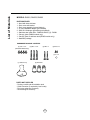
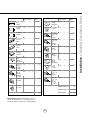
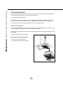
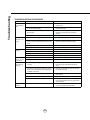
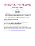
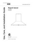
Use, Care, and Installation Guide RH00130S RH00136S RH00230G RH00236G RH00330G RH00336G RH00336S Model number: Serial Number: DEC10.0101 INSTALLATION Ducting Calculation Sheet ....................................... Mounting Height & Clearance................................ Ducting Options ........................................................... ................................................... Mounting the Hood, RH001 .................................... Mounting the Hood, RH002 ................................... Mounting the Hood, RH003 ........................... Ductless Recirculating .............................................. 5 6 7 8-10 11 12 13 14 FEATURES & CONTROLS Mechanical Controls .................................................. 15 MAINTENANCE Hood and Filter Cleaning ......................................... 16 Lights ................................................................................ 17 TROUBLESHOOTING................................................................ 18 WIRING DIAGRAMS ................................................................... 19 LIST OF PARTS AND ACCESSORIES .............................. 20 1 Table of Contents SAFETY NOTICE ................................................................. 2-3 LIST OF MATERIALS ....................................................... 4 Important Safety Notice READ AND SAVE THESE INSTRUCTIONS WARNING TO REDUCE THE RISK OF FIRE OR ELECTRIC SHOCK, DO NOT USE THIS FAN WITH ANY SOLID-STATE CONTROL DEVICE. WARNING TO REDUCE THE RISK OF FIRE ELECTRIC SHOCK, OR INJURY TO PERSONS, OBSERVE THE FOLLOWING: a. Use this unit only in the manner intended by the manufacturer, if you have questions, contact the manufacturer. b. Before servicing or cleaning unit, switch power off at service panel and lock panel to prevent power from being switched on accidentally. When the service disconnecting means cannot be locked, securely fasten a prominent warning device, such as a tag, to the service panel. CAUTION For general ventilating use only. Do not use to exhaust hazardous or explosive materials and vapors. Take care when using cleaning agents or detergents. Suitable for use in household cooking area. WARNING TO REDUCE THE RISK OF RANGE TOP GREASE FIRE: a. Never leave surface units unattended at high settings. Boilovers cause smoking and greasy spillovers that may ignite. Heat oils slowly on low or medium settings. !" #$ d. Use proper pan size. Always use cookware appropriate for the size of the surface element. %' f. Use high setting on hood only when necessary. g. Don’t leave hood unattended when cooking. h. Always use cookware and utensils appropriate for the type of and amount of food being prepared. WARNING TO REDUCE THE RISK OF INJURY TO PERSONS IN THE EVENT OF A RANGE TOP FIRE, OBSERVE THE FOLLOWING: ()*+/;(* < ' ''=*!+*/>;)?+*@*)=>+ Q '*@!>)*X!;;)*/Q+*X*?+)(*) b. NEVER PICK UP A FLAMING PAN – You may be burned. c. DO NOT USE WATER, including wet dishcloths or towels – a violent steam explosion will result. d. Use an extinguisher ONLY if: 1. You know you have a Class ABC extinguisher, and you already know how to operate it. Z ) [ ) \ ] ^ WARNING TO REDUCE THE RISK OF FIRE, ELECTRIC SHOCK OR INJURY TO PERSONS, OBSERVE THE FOLLOWING: Q # _` Q < ^ _ ` # " back-drafting. Follow the heating equipment manufacturer’s guideline and safety standards such as those published by the National / ? _/?` '+ ! * _+*` the local code authorities. c. When cutting or drilling into wall or ceiling, do not damage electrical wiring and other hidden utilities. d. Ducted fans must always vent to the outdoors. e. If this unit is to be installed over a tub or shower, it must be marked as appropriate for the application and be connected to a GFI _$/Q ` g. NEVER place a switch where it can be reached from a tub or shower. h. Make sure the power is off before installing, wiring or maintenancing. 2 TO REDUCE THE RISK OF FIRE, USE ONLY METAL DUCTWORK. NOT FOR USE IN OUTDOOR COOKING ENVIRONMENTS. CAUTION ) ^ <X"^ ' ' attics, crawl spaces or garages. OPERATION " j ' ' and loose clothing. The manufacturer declines all responsibility in the event of failure to observe the instructions given here for installation, maintenance and suitable use of the product. The manufacturer further declines all responsibility for injury due to negligence and the warranty of the unit automatically expires due to improper maintenance. ELECTRICAL REQUIREMENTS Important: Observe all governing codes and ordinances. It is the customer’s responsibility: < )# - To assure that the electrical installation is adequate and in conformance with National Electrical Code, ANSI/NFPA 70 latest edition* or CSA standards C22.1-94, Canadian Electrical Code, Part 1 and C22.2 No.0-M91 - latest edition** and all local codes and ordinances. Q ' # ground path is adequate. Do not ground to a gas pipe. ! # Do not have a fuse in the neutral or ground circuit. *National Fire Protection Association Batterymarch Park, Quincy, Massachusetts 02269 ** CSA International 8501 East Pleasant Valley Road, Cleveland, Ohio 44131-5575 This appliance requires a 120V 60Hz electrical supply and connected to an individual properly grounded branch circuit protected by a 15 or 20 ampere circuit breaker or time delay fuse. Wiring must be 2 wire with ground. Please also refer to Electrical Diagram on product. _ ` # ! # ' and install appropriate connector if necessary. RH001 & RH002 - MAX 400 Watts, 3.3 Amps RH003 - MAX 426 Watts, 3.5 Amps 3 Important Safety Notice WARNING List of Materials MODELS: RH001, RH002, RH003 PARTS SUPPLIED 1 - Hood with internal blower 1 - Duct cover wall bracket 1 - Duct cover assembly (top and bottom) 1 - 6” round backdraft damper (pre-installed) 2 - 50W GU-10 halogen light bulbs (pre-installed) 1 - Stainless steel mesh filter - RH002 & RH003, (2) - RH001 1 - Canopy, glass (RH002 models only) 1 - Canopy, glass or stainless steel (RH003 models only) 1 - Hardware package HARDWARE PACKAGE CONTENTS (4) 3/16” x 1/4” (3) M6 x 1-1/2” (RH002 & RH003 Only) (2) M6 x 1” (2) M3.5 x 8 (1) 5 x 12 (1) Suction Cup (3) Wire Nuts PARTS NOT SUPPLIED - Ducting, conduit and all installation tools - Cable connector (if required by local codes) - Duct cover extension accessory - Recirculating kit accessory 4 Equivalent number length x used = Duct pieces Total Total 3-1/ 4” x 10” 1 Ft. Rect., straight x( ) = Ft. 6”- 8” Round 30 Ft. wall cap with damper x( ) = Ft. 7” Round, straight 1 Ft. x( ) = Ft. 6”- 8” Round, 30 Ft. roof cap x( ) = Ft. 8” Round, straight 1 Ft. x( ) = Ft. 6” round to 1 Ft. 3-1/ 4” x 10” rect. transition x( ) = Ft. 3-1/ 4” x 10” 15 Ft. Rect. 90 0 elbow x( ) = Ft. x( ) = Ft. 3-1/ 4” x 10” 9 Ft. Rect. 45 0 elbow x( ) = Ft. 6” round to 16 Ft. 3-1/ 4” x 10” rect. transition 90 0 elbow 7” or 8” Round, 90 0 elbow 15 Ft. x( ) = Ft. 3-1/ 4” x 10” 24 Ft. Rect. 90 0 flat elbow x( 7” or 8” Round, 45 0 elbow 9 Ft. x( ) = Ft. 3-1/ 4” x 10” 30 Ft. Rect. wall cap with damper x( 7” or 8” 30 Ft. Round wall cap with damper x( ) = Ft. 3-1/ 4” x 10” 5 Ft. Rect. to 6” round transition x( ) = Ft. 7” or 8” Round, roof cap x( ) = Ft. 3-1/ 4” x 10” 20 Ft. Rect. to 6” round transition 90 0 elbow x( ) = Ft. 7” round to 8 Ft. 3 1/ 4” x 10” rect. transition x( ) = Ft. ) = Ft. 15 Ft. x( ) = Ft. 7” round to 23 Ft. 3-1/ 4” x 10” rect. transition 90 0 elbow x( 6” Round, 90 0 elbow 6” Round, 45 0 elbow 9 Ft. x( ) = Ft. Subtotal column 2 = Ft. Subtotal column 1 = Ft. Total ductwork Ft. ) = ) = Subtotal column 1 = Ft. Ft. Ft. Maximum Duct Length: For satisfactory air movement, the total duct length of a 3 1/ 4” x 10” rectangular 6” or 7” diameter round duct should not exceed 100 equivalent feet. 5 30 Ft. = Installation – Ducting Calculation Sheet Equivalent number length x used = Duct pieces Installation – Mounting Height & Clearance Minimum mount height between range top to hood bottom should be no less than 26”. Maximum mount height should be no higher than 34”. * Min. ducted (A) Min. recirc. (B) Max. (C) It is important to install the hood at the proper mounting height. Hoods mounted too low could mounted too high will be hard to reach and will Min 26” - Max. 34” If available, also refer to range manufacturer’s height clearance requirements and recommended hood mounting height above range. Always check your local codes for any differences. Chart A 36” * Refer to chart A on this page for actual heights RH001 RH002 RH003 A 27-1/2” 22” 23” B 32” 26” 27” C 42-1/2” 42” 42” Duct cover extension kit available for ceiling heights up to 12 feet. Turn to page 20 for part number and ordering information. DUCTING A minimum of 6” round duct must be used to ^ Always use rigid type metal ducts only. Flexible Use calculation worksheet to compute total duct _?` ALWAYS, when possible, reduce the number of transitions and turns. If a long duct run is required, increase duct size from 6” to 7” or 8”. If turns or transitions are required: Install as far away from duct opening and as far apart between the two transitions as possible. 6 DAMAGE-SHIPMENT / INSTALLATION: ? installation. Q ' unit to the store in which it was bought for repair or replacement. Q ' or replacement is the responsibility of the customer. Q _ `' be made by arrangement between customer and installer. NEVER exhaust air or terminate duct work into spaces between walls, crawl spaces, ceiling, attics or garages. All exhaust must be ducted to the outside, unless using the recirculating option. Use single wall rigid Metal ductwork only. / ")X) Some Ducting Options Roof Pitch w/ Flashing & Cap (blower housing) (blower housing) side wall cap w/ gravity damper Soffit or crawl space (blower housing) ductless recirculating side wall cap w/ gravity damper (blower housing) 7 Installation – Ducting Options WARNING FIRE HAZARD Min. Ducted - 27 1/2” Min. Recirc. - 32” 1 9/16” Maximum - 42 1/2” 12” 41.3 ° 29 15/16” or 35 7/8” 19 3/4” FRONT SIDE 3 15/16” 13/16” 3 15/16” TOP 12 5/16” 13 5/16” 3 7/16” Installation – 6 7/8” 8 3/4” BACK 8 Min. Ducted - 22” Min. Recirc. - 26” Maximum - 42” 20 19 11/16” 19 3/4” 30” or 35 7/16” FRONT SIDE 8 15/16” 6 7/8” TOP 15 1/8” 6” 16 9/16” 3 7/8” 3 15/16” BACK 9 Installation – 10 5/8” 10 3/8” 10 5/8” Min. Ducted - 23” Min. Recirc. - 27” Maximum - 42” 23 15/16” 19 3/4” 30” or 35 3/16” FRONT SIDE 8 15/16” 6 7/8” TOP 15 7/8” 6” 17 1/4” 2 5/16” 3 15/16” 3 15/16” Installation – 10 3/8” BACK 10 C/L 1. Measure from range top to hood bottom and mark line A. _Z ` Duct Cover Bracket 2. Plum and mark center line. 3 15/16” [ ( =_Z< ` B \ ( !; =_[<` 12 5/16" /_Z`^<\ =X fasten screws all the way. note: wood blocking may need to be added behind the drywall if no studs are present. Wall anchors may also be used, check local codes before using wall anchors. A 26" min +" _/Q$` Use the third 6 x1-1/4” screw with washer to further secure the hood to the wall from inside the hood. 8. Center and attach duct cover bracket to wall below _Z`^ 8. Install electrical and duct work. Seal duct work with aluminum duct tape. 9. Power up hood and check for leaks around duct tape. 10. Place telescopic duct covers onto hood and extend _`"" _Z`([^ 1 *if using hood in recirculating mode you must secure air diverter plate onto wall before installing duct work and duct covers. Turn to page 14 for more details. FIG. A Cable Lock _ ` be required by local codes. Check with local requirements and codes, purchase and install appropriate connector if necessary. Cable Lock FIG. B ! WARNING: Electrical wiring must be done by a qualified person(s) in accordance with all applicable codes and standards. This range hood must be properly grounded. Turn off electrical power at service entrance before wiring. 11 Installation – Mounting the Hood, RH001 ! CAUTION: At least two installers are required due to the weight and size of the hood. Installation – Mounting the Hood, RH002 ! CAUTION: At least two installers are required due to the weight and size of the hood. 1. Measure from range top to hood bottom and mark line A. _Z ` 2. Plum and mark center line. Duct Cover Bracket 3 [ ( =_< ` 8 15/16” \ ( !;_<` /_Z`^<Z = do not tighten all the way. Note: Wood blocking may need to be added behind the drywall if no studs are present. Wall anchors may also be used but check local codes before using wall anchors. B 15 1/8” A +"_Z` ^ +" ^_/Q$=` 26” Min. +" _/Q$` third 6 x 1-1/2” screw with washer through inside of hood ^_/Q$Z` 8. Center and attach duct cover mounting bracket to wall _Z`^ _/Q$[` Brackets are pre-installed 9. Install duct work and seal with aluminum duct tape*. Re-install junction box with cable lock and install the _/Q$=Z` 1 10. Power up hood to verify all functions and check for leaks around duct tape. 11. Place telescopic duct covers onto hood and extend _`"" _Z`([^ 2 FIG. A Z+ * If using hood in recirculating mode you must secure the air diverter plate onto wall before installing duct work and duct covers. Turn to page 14 for more details. Cable Lock Cable Lock 2 _ ` be required by local codes. Check with local requirements and codes, purchase and install appropriate connector if necessary. ! WARNING: Electrical wiring must be done by a qualified person(s) in accordance with all applicable codes and standards. This range hood must be properly grounded. Turn off electrical power at service entrance before wiring. FIG. B 12 1 1. Measure from range top to hood bottom and mark line A. _Z ` 2. Plum and mark center line. Duct Cover Bracket 3 [ ( =_< ` 8 15/16” \ ( !;_<` B /_Z`^<Z = do not tighten all the way. Note: Wood blocking may need to be added behind the drywall if no studs are present. Wall anchors may also be used but check local codes before using wall anchors. 15 7/8” A +"_Z` ^ +" ^_/Q$=` 26” Min. +" _/Q$` third 6 x 1-1/2” screw with washer through inside of hood ^_/Q$Z` Brackets are 8. Center and attach duct cover mounting bracket to wall _Z`^ _/Q$[` pre-installed 9. Install duct work and seal with aluminum duct tape*. Re-install junction box with cable lock and install the _/Q$=Z` 1 10. Power up hood to verify all functions and check for leaks around duct tape. 11. Place telescopic duct covers onto hood and extend _`"" _Z`([^ 2 FIG. A Z+ * If using hood in recirculating mode you must secure the air diverter plate onto wall before installing duct work and duct covers. Turn to page 14 for more details. Cable Lock Cable Lock 1 2 _ ` be required by local codes. Check with local requirements and codes, purchase and install appropriate connector if necessary. ! WARNING: Electrical wiring must be done by a qualified person(s) in accordance with all applicable codes and standards. This range hood must be properly grounded. Turn off electrical power at service entrance before wiring. FIG. B 13 Installation – Mounting the Hood, RH003 ! CAUTION: At least two installers are required due to the weight and size of the hood. Installation – Ductless Recirculating Ductless recirculation is intended for applications where an exhaust duct work is not possible to be installed. When converted, the hood functions as a recirculating hood rather than an exhaust hood. Fumes and exhaust ) < circulated back within the home. We recommend to ALWAYS exhaust air outside of the home by employing existing or installing new duct ' ) " ^^ is not possible should you recourse to converting the hood into a recirculating hood. j" '# ) ^ < RECIRCULATING KIT (REQUIRED IF NO DUCTING IS USED) % ' " Hood Model RH001 Models Part No. RHRK001S Filters in Pkg. 2 RH002 Models RHRK002S 2 RH003 Models RHRK003S 2 1. Purchase recirculating kit per the part number above Z ""_/Q$=` Run 6” ducting from top of hood and secure to air diverter plate. [ +" _` _` _\`([^! _/Q$=` \+<Q !"Z_ approximately every 3 to 4 months based on the average of 1 - 2 hrs. of ` Note: Refer to manual included with recirculating kit for more detailed installation instructions. Charcoal Filter Replacements Hood Model All Models Part No. Z0F-C002 Qty to Order 2 X)j!+!;/Q;)*+! to be changed more often depending on cooking habits. 14 FIG. B 3 Lights On/Off 2 Blower Speed Selection Blower Off The blower will be powered off by pressing: Blower Speed Selection Select one of three speed levels by pressing: 3 Lights On/Off Power lights on and off by pressing: 15 Features & Controls - Mechanical Controls 1 Blower Off Maintenance – Hood and Filter Cleaning SURFACE MAINTENANCE: Clean periodically with hot soapy water and clean cotton cloth. Do not use corrosive or abrasive detergent , or steel wool/scouring pads which will scratch and damage surface. For heavier soil use liquid degreaser. After cleaning it is recommended that you use non-abrasive stainless steel polish/cleaners, to polish and buff out the stainless luster and grain. Always scrub lightly, with clean cotton cloth, and with the grain. Do not use any product containing chlorine bleach. Do not use “orange” cleaners. Stainless Steel Mesh Filters )_` ) need not be replaced on a regular basis but are required to be kept clean. Remove and clean by hand or in dishwasher on low heat. Spray degreasing detergent and leave to soak if heavily soiled. X< Removing Stainless Steel Mesh Filters 1. Push in on spring loaded handle Z?" 16 CAUTION: Light bulb becomes extremely hot when turned on. DO NOT touch bulb until switched off and cooled. Touching hot bulbs could cause serious burns. Make sure all power is turned off and bulbs are not hot. +" = ' stops and falls out. Q ' ^ the bulb or use a rubber/latex glove and turn counter clockwise. Replacement bulbs are available at specialty lighting stores. Purchase type GU-10 50W halogen. For part numbers please turn to page 20 of the manual. 17 Maintenance – Lights REPLACING LIGHT BULBS Troubleshooting TROUBLESHOOTING PROCEDURES Issue Cause What to do After installation, the unit doesn’t work. 1. The power source is not turned ON. 1. Make sure the circuit breaker and the unit’s power is ON. 2. The power line and the cable locking connector is not connecting properly. 2. Check the power connection with the unit is connected properly. 3. The switch board and control board wirings are disconnected. 3. Make sure the wirings between the switch board and control board are connected properly. 4. The switch board or control board is defective. 4. Change the switch board or control board. 1. The motor is defective, possibly seized. 1. Change the motor. 2. The thermally protected system detects if the motor is too hot to operate and shuts the motor down. 2. The motor will function properly after the thermally protected system cool down. Light works, but motor is not turning. The unit is vibrating. 3. Damaged capacitor. 3. Change the capacitor. 4. The switch board or control board is defective. 4. Change defective part. 1. The motor is not secure in place. 1. Tighten the motor in place. 2. Damaged blower wheel. 2. Replace the blower. 3. The hood is not secured in place. 3. Check the installation of the hood. 4. The switch board or control board is defective. 4. Change defective part. The motor is working, but the lights are not. 1. Defective halogen bulb. 1. Change the halogen bulb. 2. The light bulb is loose. 2. Tighten the light bulb. The hood is not venting out properly. 1. The hood might be hanging to high from the cook top. 1. Adjust the distance between the cook top and the bottom of the hood within 28” and 36” range. 2. The wind from the opened windows or opened doors in the surrounding area are affecting the ventilation of the hood. 2. Close all the windows and doors to eliminate 3. Blockage in the duct opening or ductwork. 3. Remove all the blocking from the duct work or duct opening. 4. The direction of duct opening is against the wind. 4. Adjust the duct opening direction. 5. Using the wrong size of ducting. 5. Change the ducting to at least 6” or higher for the internal blower and 8” or higher for the external blower. ( 1. Make sure the metal clips in the handle are Metal Filter is vibrating. 18 Wiring Diagrams RH00130S/136S 3.3A RH00230G/236G 3.3A RH00330G/336G/336S 426W 326W 19 List of Parts & Accessories DESCRIPTION PART# Replacement Parts ; =$><j_` =<Z Optional Accessories + % ++%_+` ++%Z_+Z` ++%[_+[` Replacement Charcoal Filter Z0F-C002 X!"*^ _Z ` +*_+` +*Z_+Z+[` To order parts, visit us online at www.ventingservices.com or call us at 1.888.750.1698 20 21