1
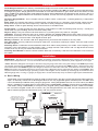
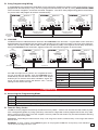
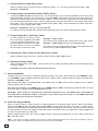
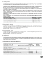
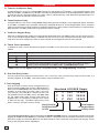
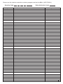
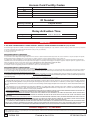
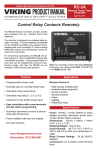
Designed, Manufactured and Supported in the USA
VIKING PRODUCT MANUAL
C O M M U N I C AT I O N & S E C U R I T Y S O L U T I O N S
ES-1
Stand Alone Door
Controller Entry System
February 4, 2014
Add Keyless Entry and/or Card Reader Entry for a
Single Door with Up to 250 Users
The ES-1 is a door controller designed to operate
a door strike or magnetic lock upon receiving a
valid card read and/or keyless entry code from Wiegand devices. One ES-1, one or two Wiegand devices and a door strike or magnetic lock of your
choice is required for each entry point.
The Wiegand device used may be the Viking
model PRX-1 Proximity Card Reader and/or the
PRX-2 Proximity Card Reader with Keypad, PRX3 Medium Range Proximity Card Reader or or
PRX-4 Wiegand Output Keypad or any other card
reader, RF transmitter or digital keypad that outputs
the 26 bit Wiegand format. If two Wiegand devices
are used, one can be placed on each side of a
doorway to control access in both directions (entry
and exit). Up to 250 valid Wiegand codes can be
programmed into the ES-1.
Other programmable parameters, like relay activation, mode (normal, off, or open) and facility codes
are also stored in non-volatile memory. All programming is done with a local touch tone phone. Up to
three ES-1s can be programmed simultaneously if
they will be sharing all the same programming
codes and parameters. Entry logging is possible
with the ES-1’s log bus data output.
Features
Applications
• Up to 250 tenants
• Program and control with a Touch Tone phone
• Use with any 26 bit Wiegand device
• Supports 1 entry point
• Compatible with Viking models PRX-1, PRX-2
PRX-3, and PRX-4 and certain legacy 125KHz
HID® proximity card readers*
•
•
•
•
•
•
•
Business entrances
High rise apartment buildings
Condos
Senior citizen buildings
Assisted care centers
Retirement homes
Gated communities
• Non-volatile memory (no batteries required)
• LOG BUS data output for logging entry events
• Card plus keypad mode for highest security
• One time codes for visitors
• Bi-directional (entry and exit) control
www.vikingelectronics.com
Information: (715) 386-8861
* HID and the HID logo are registered trademarks of HID
Global Corporation, an ASSA ABLOY company. All other
trademarks are the property of their respective owners.
Specifications
Power: 120V AC/12V DC 500mA, UL listed adapter provided or use any 12-24V AC or DC source @ 100mA (designed to share power with the door strike’s power supply)
Dimensions: 133mm x 89mm x 44mm (5.25” x 3.5” x
1.75”)
Shipping Weight: 1.3 kg (3 lbs)
Environmental: 0° C to 32° C (32° F to 90° F) with 5%
to 95% non-condensing humidity
Relay Contact Ratings: 5A @ 30V DC/250V AC maximum
Maximum Wiegand Length: 152m (500 ft) - 24 AWG
Maximum LOG BUS Length: 1610m (5280 ft - 1 mile),
24 AWG
Connections: 11 screw terminals, (1) RJ-11 telco jack
Definitions
26 Bit Wiegand Format: The industry standard data output of access control card readers.
Bi-Directional Access: Two Wiegand devices can be wired in parallel to one ES-1 to control access in both directions
at a single entry point. Simply place one card reader on each side of the door or gate. When either one detects a valid
code, the ES-1 will strike the door. Data logging will not be able to distinguish the direction of the access. If that is a
requirement, two separate ES-1s will need to be installed, so each one can log separate access events from each
side of the door.
Card Plus Keypad Mode: This is a higher security mode in which a valid card + a valid keypad entry is required to
gain access.
Entry Code: The number that when it matches either a Keyless Entry or a Proximity Card number, allows access.
Each tenant may have their own unique Entry Code that is easily changed or removed when a tenant moves out.
Entry Point: A door or gate allowing access into a secure or controlled area.
Facility Code: A 3-digit number that each proximity card contains in order to provide greater security. Usually the
cards used at a given building all have the same facility code.
Keyless Entry: A way for tenants to let themselves in, by entering their entry code on a keypad.
LOG BUS: A two wire data bus that can be wired in parallel with additional ES-1 log busses. Data is sent as 1200
baud ASCII characters at TTL levels (0-5 Volt). Any RS-232 port designed to receive TTL levels can receive log bus
data directly on the “Receive Data” and “Signal Ground” pins.
Memory Location: The number used when programming, that stores the location of an entry code.
One Time Code: An entry code that can only be used once - this feature is handy for visitors. Once the code is used
the ES-1 forgets it.
Proximity Card: A credit size card that identifies itself when within close proximity of a reader. Card “swiping” is not
necessary. The card contains a 3 digit Facility Code, a 5 digit Internal Card number and a 5 digit External Printed
number, that may or may not match the Internal number.
Proximity Card Reader: A device used to read the data from a Proximity Card when its held within a few inches of
the reader.
Installation
IMPORTANT: Electronic devices are susceptible to lightning and power station electrical surges from both the AC
outlet and the telephone line. It is recommended that a surge protector be installed to protect against such surges.
* Note: Maximum Wiegand run length is 600 feet using 24 gauge wire when using the Viking model PRX-1 proximity
card reader, 500 feet for the PRX-2 keypad/proximity card reader, 800 feet for the PRX-3 (using 3 wire pairs for pwr)
and 2000 feet for the PRX-4 keypad. Run length is reduced to half if two share the same wire run from the same C4000 entry point. Run length will also be reduced if using a Wiegand device other than the Viking model PRX-1, that
requires more than 35mA average operating current. Run lengths can be doubled by doubling up on the BLACK and
RED 24 gauge wire, or using 21 gauge (or larger) wire. Certain electrically noisy locations might require shielded wire.
A. Basic Wiring
A basic door access controlled entry point is wired as shown below. The relay can be connected as either Normally
Open, or Normally Closed. All 26-bit Wiegand devices are fully supported (power and data) from the ES-1 and
can be installed up to 500 feet away using 24 gauge wire. Viking Wiegand devices can run even further (see Note
above). The ES-1 can support either a card reader (Viking model PRX-1 or PRX-3), keyless entry keypad/proximity
card reader (Viking model PRX-2) or a keyless entry keypad (Viking model PRX-4), or both. If both are installed,
the “Card Plus Keypad” mode can be used. If any two Wiegand devices are used, one can be placed on each
side of a doorway/gate for bi-directional (entry and exit) access control.
MODEL ES-1
VIKING
ELECTRONICS
HUDSON, WI 54016
WIEGAND
DEVICE
7
8
9 10 11
GRN
RED
5 6
WHT
BLK
DOOR
STRIKE
N.C.
GANG
PROG
3 4
N.O.
2
2
1
COM
POWER
LOG
BUS
PROGRAM
PHONE
1
Doorstrike
Power Supply
12-24V AC or DC
L
STAND ALONE
DOOR CONTROLLER
ENTRY SYSTEM
H
OR
POWER 12V DC
Share power with 12-24V
AC/DC doorstrike with 200mA
available current or use the
included 12V DC adapter.
VIKING ©
12V DC
Adapter
(included)
* 610m (2000 ft) max
Doorstrike
* 152m (500 ft) max
Remote Touch Tone
Programming Phone
(not included)
RAD-1A Remote Access
Device (not included,
see DOD# 410)
Touch Tone
Programming Phone
(not included)
- or OR
OR
* 183m (600 ft) max
or
2
Viking PRX-1
(not included
DOD# 221)
Viking PRX-2
(not included
DOD# 219)
Viking HID-2
(not included
DOD# 199)
B. Gang Programming Wiring
If multiple ES-1s are installed to handle door access control for multiple entry points, two or three of them can be
programmed simultaneously if they are to be programmed identically. Do this by wiring GANG PROG COMM
screw terminals 1 together, and screw terminals 2 together. The touch tone programming phone connected to
any one of them will program all of them simultaneously.
VIKING ©
1
2
1
1
RED
DOOR
STRIKE
COM
BLK
5 6
7
8
9 10 11
GRN
3 4
N.C.
LOG
BUS
GANG
PROG
2
N.O.
1
2
609m (2000 ft) maximum
with 24 gauge wire
Touch Tone
Programming
Phone
POWER
2
PROGRAM
PHONE
1
9 10 11
L
8
H
POWER 12V DC
WIEGAND
DEVICE
7
GRN
5 6
WHT
RED
DOOR
STRIKE
COM
3 4
BLK
2
N.O.
1
N.C.
LOG
BUS
GANG
PROG
POWER
2
PROGRAM
PHONE
1
9 10 11
L
8
H
POWER 12V DC
WIEGAND
DEVICE
7
GRN
5 6
WHT
RED
DOOR
STRIKE
COM
BLK
3 4
N.O.
2
2
1
N.C.
POWER
LOG
BUS
STAND ALONE
DOOR CONTROLLER
ENTRY SYSTEM
GANG
PROG
STAND ALONE
DOOR CONTROLLER
ENTRY SYSTEM
1
STAND ALONE
DOOR CONTROLLER
ENTRY SYSTEM
WIEGAND
DEVICE
MODEL ES-1
VIKING
ELECTRONICS
HUDSON, WI 54016
WHT
MODEL ES-1
VIKING
ELECTRONICS
HUDSON, WI 54016
L
PROGRAM
PHONE
VIKING ©
MODEL ES-1
VIKING
ELECTRONICS
HUDSON, WI 54016
H
POWER 12V DC
VIKING ©
2
609m (2000 ft) maximum
with 24 gauge wire
C. LOG BUS
The ES-1 transmits 1200 baud ASCII data from the LOG BUS screw terminals. Log Bus data is sent each time
Wiegand data is received from the entry point, and includes: an entry point ID number, if the entry was valid, nonvalid, or off, the facility code, and the card number (or keypad entry code). The Log Bus can be daisy-chained by
wiring the LOG BUS screw terminals L together and screw terminals H together as shown below.
H
Brown
(Receive Data)
L
Yellow
(Signal Ground)
H
L
H
L
H
7
8
9 10 11
GRN
5 6
WHT
BLK
RED
DOOR
STRIKE
GANG
PROG
3 4
COM
2
N.O.
1
2
1
POWER
N.C.
PROGRAM
PHONE
L
9 10 11
LOG
BUS
8
H
POWER 12V DC
WIEGAND
DEVICE
7
GRN
BLK
5 6
WHT
N.C.
RED
DOOR
STRIKE
GANG
PROG
3 4
N.O.
2
2
1
COM
POWER
1
PROGRAM
PHONE
L
9 10 11
LOG
BUS
8
H
WIEGAND
DEVICE
7
GRN
5 6
WHT
BLK
DOOR
STRIKE
N.C.
RED
3 4
N.O.
2
2
1
COM
POWER
POWER 12V DC
STAND ALONE
DOOR CONTROLLER
ENTRY SYSTEM
GANG
PROG
STAND ALONE
DOOR CONTROLLER
ENTRY SYSTEM
1
STAND ALONE
DOOR CONTROLLER
ENTRY SYSTEM
WIEGAND
DEVICE
MODEL ES-1
VIKING
ELECTRONICS
HUDSON, WI 54016
LOG
BUS
PROGRAM
PHONE
VIKING ©
MODEL ES-1
VIKING
ELECTRONICS
HUDSON, WI 54016
L
Pin 5
(Signal
Ground)
VIKING ©
MODEL ES-1
VIKING
ELECTRONICS
HUDSON, WI 54016
H
Pin 2
(Receive
Data)
POWER 12V DC
VIKING ©
DB-9
(not included)
L
24 gauge wire
1610m (5280 ft - 1 mile)
maximum run length
Communication Software Configuration
If the RS-232 input of a PC, printer, etc. is capable of receiving TTL level RS-232 signals, then the LOG BUS can be
wired directly into the RS-232 “Receive Data” and “Signal
Ground” pins to receive ASCII data. Windows “Hyper-Terminal” can be used to receive the data on a PC. Use the
settings in the chart at the right:
Com
Your serial port (1-4)
Baud rate
1200
Data Bits
8
Stop Bits
1
Parity
none
Flow Control
none
Programming
A. Accessing the Programming Mode
Step 1. Connec t a touch tone phone to the PROGRAM PHONE jack.
Step 2. Come off-hook. A double beep will indicate that programming has been entered.
Step 3. Program as shown in section B - I.
Step 4. To exit programming, simply hang up the phone.
B. Tenant’s Entry Codes
The ES-1 can be programmed with up to 250 tenant entry codes. A tenant can activate the door strike, keyless,
from a Wiegand keypad or by using a proximity card with its 5 digit card number programmed as the entry code.
When a given tenant moves out of the complex, the entry code for that tenant may be cleared without affecting
any other tenant’s entry code.
Important: 26-bit Wiegand data limits the entry code range from 00001 to 65535. Entry codes larger than 65535
will not work.
WARNING: If using a Viking model PRX-4 keypad, do not program the ES-1 to accept entry code 65535 because that is the keypad’s error code.
3
1. Programming a single Entry Code
While in programming, enter the tenant’s 5 digit entry code + “#” + memory location number (001 - 250).
Example: 12345 # 001
2. Programming a continuous Bank of Entry Codes
If using the PRX-4 keypad for keyless entry, it is an advantage, from a security standpoint, to have the entry
codes all random numbers. On the contrary, if using the PRX-1 card reader, proximity cards are typically purchased as a continuous bank of incrementing numbers. If this is the case, a large block of incrementing numbers can be programmed all at once. While in programming, enter the first (lowest value) 5 digit card number
entry code + “#” + the starting memory location number (001 - 249). After two beeps are heard, enter #Q +
the ending memory location (002 - 250).
Example: 10300 # 001 (wait for two beeps) #Q 150
This will fill memory positions 001 through 150 sequentially with entry codes 10300 through 10450.
3. Programming One Time Entry Codes
An entry code that can only be used
once, and is then forgotten by the ES1, can be programmed similar to a single entry code or a bank of entry codes
as shown above. An extra “Q” before
the “#” makes it a one time code.
Example: 12345 Q# 001
This will fill memory position 001 with one time entry code 12345.
Example: 10300 Q# 001 (wait for two beeps) #Q 150
This will fill memory positions 001 through 150 sequentially with
one time entry codes 10300 through 10450.
4. Deleting the Entry Code for One Memory Location
While in programming, enter “#” + memory location number (001 - 250) to clear.
5. Deleting all Entry Codes
While in programming, enter “###”. This will clear all entry codes, all facility codes, and set all programming
to factory settings.
CAUTION: All entry codes will be permanently erased.
C. Operating Modes
The ES-1 can be set into one of 3 different operating modes. The factory default setting is the NORMAL mode.
In the NORMAL mode, the ES-1 strikes the door when a proper card or keyless code is entered. Enter Q1 to put
the ES-1 in NORMAL mode.
Enter Q0 to put the ES-1 in the OFF mode. In the OFF mode, the ES-1 will not strike the door, even if a proper
card or keyless code is entered.
Enter Q2 to put the ES-1 in the OPEN mode. In the OPEN mode, the ES-1 continuously strikes the door. No card
or keyless code is needed, and no LOG BUS data is sent.
CAUTION: Some strikes are designed for intermittent operation only. The OPEN mode should NOT be
used with these intermittent strikes, or damage to the strike may occur. Only use the OPEN mode with
strikes designed for continuous operation.
D. Card Plus Keypad Mode
This is a mode in which a valid card, plus a valid keypad entry is required to gain access. Both a card reader
(Viking model PRX-1) and a keypad (Viking model PRX-4) are required at the entry entry point. A higher level of
security is achieved because acquiring someone’s card is not enough to gain access. The number to be entered
on the keypad must match the 5-digit internal card number. Because of this, it is important the actual 5-digit card
number is not printed on the card itself.
While in programming, enter “Q7” to put the ES-1 into the Card Plus Keypad mode, or enter “Q8” to remove the
ES-1 from this mode.
Note: The cards can have a facility code of 001 to 254, but the keypad in use must have its facility code programmed to 255, so the ES-1 knows one from the other (see section E).
4
E. Facility Codes
A Wiegand type card reader can be added to the ES-1 entry point for card access control. Twenty-six bit Wiegand
access cards, such as Viking’s model PRX-C, identify themselves with an 8-digit number. The first three digits
are considered the Facility Code and the last five are the card number.
The ES-1 shares the 5 digit entry code memory location for both keypad entry and card entry. In other words, the
5-digit card number is to be programmed as the tenant’s entry code. Unless facility codes are programmed, the
ES-1 will only need to match the 5-digit card number with any programmed entry code to allow access.
For a higher level of security the 3-digit Facility Code should be programmed. Each ES-1 can be programmed to
accept up to 4 different Facility Codes.
Note: If all 4 Facility Code locations are programmed to “000” (factory setting), the ES-1 will disregard the Facility
Code all together, thus making access entry based only on the card number (or keypad entry) match with the
programmed entry code.
Important: 26-bit Wiegand data limits the facility code range from 001 to 255. A facility code larger than 255 will
not be accepted.
When in programming, enter the 3-digit Facility Code of the access cards being used, then “#” and the memory
locations as follows:
Programming Facility Codes
Enter Digits
+ Location
First Facility Code (default = 0000) ………………......................................….......... 3 digits (0-9) + #911
Second Facility Code (default = 0000) …………………..................…...................... 3digits (0-9)
+ #912
Third Facility Code (default = 0000) ....................................................................... 3digits (0-9)
+ #913
Forth Facility Code (default = 0000) ........................................................................ 3digits (0-9)
+ #914
F. Entry Point ID Number
The ES-1 outputs event data on the LOG BUS each time a card or keypad is used. An ID number can be programmed in each ES-1 so that the device receiving the LOG BUS data knows which entry point the event came
from. While in programming, enter a single digit ID number (1-9) + ##7.
Example: 6 ##7 = an Entry Point ID number of 6
G. Relay Activation Time
The relay activation time can be programmed in seconds from 01 - 99. When in programming, enter the time in
seconds + ##3 (00 = 1/2 second, factory set to 5 seconds).
Example: 05 ##3 = a 5 second relay activation time
H. Beep Tones
While programming the ES-1, a double beep will be heard after entering a valid command or memory location. If
an invalid command or number sequence is entered, it will be indicated by a triple beep. If an error is made, review
the instructions and re-program that location. The ES-1 is capable of detecting hardware memory errors and will
output 4 beeps if there is a problem.
I. Programming Features Quick Reference
Description
Enter Digits
+ Location
A single Entry Code …………………………………................................................….. 5 digits (0-9)
+ #001-250
A single one time use entry code ………………….......................................…............. 5 digits (0-9)
+ Q#001-250
Continuous bank of entry codes.......................... Enter first code, then #, then first location, then #Q + last location
Clear one entry code ................................................................................................... no digits
+ #001-250
Off mode ..................................................................................................................... Q0
Normal Mode (factory setting)...................................................................................... Q1
Open mode (only use with compatible strikes, see Programming, section C)........... Q2
Touch tone door strike activation ................................................................................. Q6
Card plus keypad mode enabled ................................................................................. Q7
Card plus keypad mode disabled (factory setting) ...................................................... Q8
#41
Entry point ID number (factory set to 1) ....................................................................... 1 digit (00-01)
##7
Relay activation time (in seconds - factory set to 5 seconds) ...................................... 2 digits (00-20)
+ ##3
facility codes (all factory set to 000) ............................................................................ 3 digits (00-99)
+ #911-914
Clear all entry codes and return all programming features back to factory settings .... ### (CAUTION: Erases all Programming!)
5
Operation
A. Tenant Card Reader Entry
A Wiegand device, such as the Viking PRX-1 Proximity Card Reader (not included), is fully supported (power and
data) by the ES-1. The ES-1 entry controller monitors the Wiegand devices for 26 bit Wiegand data. When a card
is read, the data is compared against the Facility Code (if used) and Entry Code data bases programmed in the
ES-1, and access is granted if a match is found.
B. Tenant Keyless Entry
A Wiegand device, such as the Viking PRX-4 Wiegand Keypad (not included), is fully supported (power and data)
by the ES-1. The ES-1 entry controller monitors the Wiegand devices for 26 bit Wiegand data. When a keyless
code is entered on the keypad, the data is compared against the Facility Code (if used) and Entry Code data base
programmed in the ES-1, and access is granted if a match is found.
C. Card Plus Keypad Entry
With both a Wiegand card reader and a Wiegand keypad wired to the same ES-1, either can be used to gain access. If the card plus keypad mode is enabled, first the card must match a programmed facility code and entry
code, then the same 5-digit entry code must be entered on the keypad for access to be granted.
D. Touch Tone Commands
In addition to using a Touch Tone phone to program the ES-1, a few Touch Tone commands are also available as
follows:
Touch Tone Command Description
Q0
To put the ES-1 in the OFF mode ( no cards or keyless entry numbers grant access).
Q1
To put the ES-1 back in the Normal mode .
Q2
To have the ES-1 continuously strike the door/gate (*Open mode), no LOG BUS data is sent
Q6
To momentarily strike the ES-1, this allows someont twithin the building to allow a
visitorin, even if the ES-1 IS in the OFF mode , no LOG BUS data is sent.
* Note: Only use the Open mode with compatible strikes (see Programming, section C).
E. One time Entry Codes
An entry code can be programmed for one time use. If this is the case, once the entry code has been used, it is
instantly forgotten by the ES-1. This feature allows visitors limited access.
F. Data Logging
Each time either a card is read or a keypad entry has
been received, the ES-1 will transmit 1200 baud ASCII
data out of its LOG BUS screw terminals. Data sent
includes: an entry point ID number (1-9), if the entry
was valid (V), non-valid (N) or valid but access was
not granted because the ES-1 was in the OFF mode
(F), the 3-digit facility code, and the card number (or
keypad entry). An example of 3 different entry events
is shown to the right. The ES-1 outputs entry event
data in real time, but does not time stamp.
Simulated LOG BUS Output
1
2
1
Entry Point ID
Valid, Not-Valid,
or OFF
V
N
F
255
132
255
12345
06336
12345
Card Number
or Keypad Entry
Facility Code
Visit www.vikingelectronics.com to download free ENTRY LOGGER software. The software provides transaction
logging for the ES-1 and C-4000 Entry Controller systems. Compatible with any Windows based PC running Windows 95 or higher, the software adds time and date stamps to each transaction, and allows user printing, record
saving, and complete search capabilities.
6
Please use this chart to record the numbers programmed into the ES-1 (USE PENCIL)
Security Code:
Memory Location
Relay Activation Code:
Tenant’s Name
Entry Code #
7
Access Card Facility Codes
Facility Code
Memory Location
911
912
913
914
ID Number
Memory Location
1-Digit ID Number
##7
Relay Activation Time
Memory Location
Time in Seconds
##3
Warranty
IF YOU HAVE A PROBLEM WITH A VIKING PRODUCT, CONTACT: VIKING TECHNICAL SUPPORT AT (715) 386-8666
Our Technical Support Department is available for assistance Monday 8am - 4pm and Tuesday through Friday 8am - 5pm central time. So that we can give you better service, before you call please:
1. Know the model number, the serial number and what software version you have (see serial label).
2. Have your Technical Practice in front of you.
3. It is best if you are on site.
RETURNING PRODUCT FOR REPAIR
The following procedure is for equipment that needs repair:
1. Customer must contact Viking's Technical Support Department at 715-386-8666 to obtain a Return Authorization (RA) number. The customer MUST have a complete description of the problem,
with all pertinent information regarding the defect, such as options set, conditions, symptoms, methods to duplicate problem, frequency of failure, etc.
2. Packing: Return equipment in original box or in proper packing so that damage will not occur while in transit. Static sensitive equipment such as a circuit board should be in an anti-static bag,
sandwiched between foam and individually boxed. All equipment should be wrapped to avoid packing material lodging in or sticking to the equipment. Include ALL parts of the equipment. C.O.D. or
freight collect shipments cannot be accepted. Ship cartons prepaid to: Viking Electronics, 1531 Industrial Street, Hudson, WI 54016
3. Return shipping address: Be sure to include your return shipping address inside the box. We cannot ship to a PO Box.
4. RA number on carton: In large printing, write the R.A. number on the outside of each carton being returned.
RETURNING PRODUCT FOR EXCHANGE
The following procedure is for equipment that has failed out-of-box (within 10 days of purchase):
1. Customer must contact Viking’s Technical Support at 715-386-8666 to determine possible causes for the problem. The customer MUST be able to step through recommended tests for diagnosis.
2. If the Technical Support Product Specialist determines that the equipment is defective based on the customer's input and troubleshooting, a Return Authorization (R.A.) number will be issued.
This number is valid for fourteen (14) calendar days from the date of issue.
3. After obtaining the R.A. number, return the approved equipment to your distributor, referencing the R.A. number. Your distributor will then replace the Viking product using the same R.A. number.
4. The distributor will NOT exchange this product without first obtaining the R.A. number from you. If you haven't followed the steps listed in 1, 2 and 3, be aware that you will have to
pay a restocking charge.
TWO YEAR LIMITED WARRANTY
Viking warrants its products to be free from defects in the workmanship or materials, under normal use and service, for a period of two years from the date of purchase
from any authorized Viking distributor. If at any time during the warranty period, the product is deemed defective or malfunctions, return the product to Viking Electronics,
Inc., 1531 Industrial Street, Hudson, WI., 54016. Customer must contact Viking's Technical Support Department at 715-386-8666 to obtain a Return Authorization (R.A.)
number.
This warranty does not cover any damage to the product due to lightning, over voltage, under voltage, accident, misuse, abuse, negligence or any damage caused by
use of the product by the purchaser or others. This warranty does not cover non-EWP products that have been exposed to wet or corrosive environments. This warranty
does not cover stainless steel surfaces that have not been properly maintained.
NO OTHER WARRANTIES. VIKING MAKES NO WARRANTIES RELATING TO ITS PRODUCTS OTHER THAN AS DESCRIBED ABOVE AND DISCLAIMS ANY EXPRESS OR IMPLIED WARRANTIES OR MERCHANTABILITY OR FITNESS FOR ANY PARTICULAR PURPOSE.
EXCLUSION OF CONSEQUENTIAL DAMAGES. VIKING SHALL NOT, UNDER ANY CIRCUMSTANCES, BE LIABLE TO PURCHASER, OR ANY OTHER PARTY,
FOR CONSEQUENTIAL, INCIDENTAL, SPECIAL OR EXEMPLARY DAMAGES ARISING OUT OF OR RELATED TO THE SALE OR USE OF THE PRODUCT SOLD
HEREUNDER.
EXCLUSIVE REMEDY AND LIMITATION OF LIABILITY. WHETHER IN AN ACTION BASED ON CONTRACT, TORT (INCLUDING NEGLIGENCE OR STRICT LIABILITY)
OR ANY OTHER LEGAL THEORY, ANY LIABILITY OF VIKING SHALL BE LIMITED TO REPAIR OR REPLACEMENT OF THE PRODUCT, OR AT VIKING'S OPTION,
REFUND OF THE PURCHASE PRICE AS THE EXCLUSIVE REMEDY AND ANY LIABILITY OF VIKING SHALL BE SO LIMITED.
IT IS EXPRESSLY UNDERSTOOD AND AGREED THAT EACH AND EVERY PROVISION OF THIS AGREEMENT WHICH PROVIDES FOR DISCLAIMER OF WARRANTIES, EXCLUSION OF CONSEQUENTIAL DAMAGES, AND EXCLUSIVE REMEDY AND LIMITATION OF LIABILITY, ARE SEVERABLE FROM ANY OTHER PROVISION AND EACH PROVISION IS A SEPARABLE AND INDEPENDENT ELEMENT OF RISK ALLOCATION AND IS INTENDED TO BE ENFORCED AS SUCH.
Product Support: (715) 386-8666
Due to the dynamic nature of the product design, the information contained in this document is subject to change without notice. Viking Electronics, and its affiliates
and/or subsidiaries assume no responsibility for errors and omissions contained in this information. Revisions of this document or new editions of it may be issued
to incorporate such changes.
8
DOD# 193
Printed in the U.S.A.
ZF301940 Rev B