1
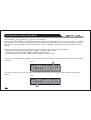
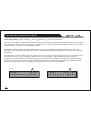
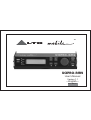
TM
LTO
UCSPRO-RM2
User's Manual
Version 1.1
---English--PRELIMINARY
Safety Instructions
TM
LTO
All safety and operating instructions - including those supplied with the UCS PRO - should be read before the
UCSPRO-RM2 is installed and operated. We recommend that installation be carried out by an authorized
TM
mobile electronics installation company. Please contact your local ALTO Mobile distributor for a list of
authorized installers in your country.
To reduce the risk of electric shock and potentially damaging the equipment, do not disassemble the
product. No user serviceable parts inside; refer servicing to qualified personnel.
These installation and operating instructions should be read in conjunction with the instructions supplied
with your Alto Mobile UCS PRO audio processor. Retain for future reference.
Avoid installing and/or using the UCSPRO-RM2 in a location that could interfere with the operation of the
vehicle or its controls, or distract the driver's attention.
The equipment should be protected from moisture, rain and heat.
The UCSPRO-RM2 is designed exclusively for use with the Alto Mobile UCS PRO audio processor. Do not
attempt to use the UCSPRO-RM2 with any other product, even if the connector plug physically fits. The pin
wiring and data protocols will not be compatible with other products and could cause damage to both
products.
This product is designed for vehicles with a 12-VOLT NEGATIVE GROUND electrical circuit. This product
is not suitable for vehicles that use a 24-Volt supply or a positive ground electrical circuit. Connection to
such circuits may permanently damage the unit.
1
TM
LTO
Introduction
Thank you for choosing the ALTO Mobile TM UCSPRO-RM2 Programmer for the Alto Mobile UCS PRO digital
signal processor. The UCSPRO-RM2 provides an alternative to using a Personal Computer (PC) for setting
the various functions of the UCS PRO. It is primarily designed to be bolted to the UCS PRO but can be
detached and, using an optional extension data cable, used remote from the main unit (such as handheld at
the driver's seat) during system set-up.
While unable to offer the advanced graphics interface available when using the PC Editor, the UCSPRO-RM2
does offer all the same control and set-up functions. It does this via a very intuitive set of controls, a multilayer menu system, and its own backlit LCD display.
The UCS PRO is a 2 input, 6 output device offering several forms of signal processing designed to
manipulate and enhance the audio signal in a number of ways. These include multiband parametric
equalization, high-pass and low-pass filters, digital channel delay (time alignment), phase alignment,
multichannel dynamic control (compressor/limiter), noise gating and full input/output gain setting in the
digital domain. The addition of the UCSPRO-RM2 makes the UCS PRO a completely self-contained "car
audio tweaker's paradise", allowing system set-up, further fine adjustment and preset selection to be done at
any time without the need to hook-up a computer.
We have attempted to provide detailed instructions in this manual, but it does assume that the person
installing and setting up the equipment already has a good level of knowledge of the subject. If you have had
your UCS PRO professionally installed and set-up for you, please be aware that altering the settings may
damage audio system components.
NOTE: The UCS PRO has a password access system that your installer may have set in Lock mode to
safeguard the settings. If you are unable to access menu items with the UCSPRO-RM2, check with your
dealer.
2
Introduction
TM
LTO
Block Diagram: UCS PRO
There are no controls on the UCS PRO itself. Setting the parameters of the UCS PRO is achieved in one of
two ways - either by using the UCSPRO-RM2 Programmer, or by connecting a suitable computer to the 9-pin
RS232 serial interface and running Alto's dedicated PC Editor software. Set-up using a PC is covered in the
UCS PRO user manual and the program's Help file
3
TM
LTO
CONNECTING THE RM2 TO THE UCS PRO
Ensure power to the UCS PRO and the rest of the audio system is switched OFF .
At each side of the panel of the UCS PRO that carries the 25-pin connector, remove the bolts securing the
cover of the UCS PRO*. You will need a suitable Allen key to remove these bolts.
( * The top cover of the UCS PRO may also be completely removed, rotated 180 degrees and refitted so that
the inscription faces forward. We recommend your dealer does this for you).
A D-SUB 25-pin male terminal on the UCS PRO mates with the recessed 25-pin female socket on the rear of
the UCSPRO-RM2 Programmer. The connectors are shaped in such a way that they will fit together only
when correctly aligned.
Line-up the two terminals carefully and then gently exert even pressure, bringing both parts together so that
the terminals mate correctly.
DO NOT APPLY EXCESSIVE FORCE.
There should be no need to apply more than moderate pressure when bringing the two devices together. The
extended side panels of the UCSPRO-RM2 will help to correctly align the two devices.
The two devices should fit together without a gap between them, and the fixing holes should align at each
side. Secure the RM2 to the UCS PRO by bolting the extended side panels of the RM2 to the sides of the
UCS PRO using the mounting bolts provided.
4
Using the RM2 remotely from the UCS PRO
TM
LTO
If you wish to use the UCSPRO-RM2 remotely from the main UCS PRO, you will need to obtain a Serial DB25
(25-pin) male-female Extension cable (not supplied). For example, Belkin 3m extension cable, code
F3D112b10, or other computer grade extension data cable. Ask your Alto dealer or local computer retailer.
Avoid using a cable length of more than 5 meters - with long cables, inferior types of cable, and in areas of
high emitted interference, reliable data transmission cannot be guaranteed.
NOTE: Do not connect your PC or printer to the 25-pin connectors of the UCS PRO or UCSPRO-RM2
Programmer. The data on the pins will not be compatible and damage may result.
5
TM
LTO
EDITING PARAMETERS USING THE RM2
The UCSPRO-RM2 uses a backlit LCD display, a set of buttons and a very user-friendly, continuously
adjustable rotary control to allow full editing control of the UCS PRO. When you switch on power to the
UCS PRO, the RM2 will show an initial welcome screen (showing the internal software version number). This
will last for about 5 seconds while the UCS PRO initialises. During this period it restores the set-up that was
active when it was last switched off.
The display will then switch to the last selected Preset (or the factory Default Preset). The Channel
Configuration will be shown in the display. The bold letters represent the input channels A and B (typically
the left and right channel respectively). The numbers after the letters show which output channels are fed
from each input. For example, A 135 signifies that Input Channel A is feeding Output Channels 1, 3 and 5.
At the far left of the Programmer is a MODE button next to 4 LEDs labelled Preset , Delay , Edit , Utility . Press
the MODE button to sequentially step through the 4 options. Each option provides access to the following
parameters:
Preset - accesses the menus for loading and saving presets.
Delay - accesses the menus for adjusting delay time on the input and output channels.
Edit - accesses the menus for adjusting the Input Gains, Noise Gate, Input EQ, Crossover Filters, Output
EQ, Compressor/Limiting, Output signal Polarity and Output Gains.
Utility - accesses menus for selecting the stereo Ganging option, changing the type of unit used in the
menus (i.e. millimetres, microseconds etc.), setting the Lock mode, and various other parameters.
Imagine the various menus as having multiple layers. Follow this example to see it in action
(1) Use the MODE button to select the Delay option (the LED next to Delay lights). The display shows Input
Delay . Press the button marked NEXT. The display now shows Output Delay . By pressing the NEXT and
PREV (Previous) buttons you can step through the various top-level options in this menu.
(2) With the display showing Output Delay , press the button marked ENTER. This takes you down one level
in the menu structure. The display will now show OP1 DELAY (or OP1&2 DELAY) with a flashing digit
6
EDITING PARAMETERS USING THE RM2
TM
LTO
below, indicating that it is an editable parameter. Now you can use the rotary knob to change the value.
Once you have set the required value, simply press the ESC (Escape) button. This will take you one level
back up the menu tree.
(3) Your selected value has already been stored. If you now use the MODE button to get you back to the startup display (press MODE 3 times), you will now see an " M " (for Modified) in the start-up display. This warns
you that the original set-up has been changed. This "modified" status will be retained even if power to the
UCS PRO is switched off. However, you must store your set-up under a new Preset Number before
loading another Preset, otherwise your changes will be lost.
This same procedure applies to all the options and menus editable via the RM2 Programmer. In some cases
you will also use the 2 arrow buttons (below PREV and NEXT), where multiple choices are presented on one
screen.
For example, using the MODE button select Edit and then use the PREV or NEXT buttons until you reach
Noise Gate . Press ENTER. The LCD screen now presents you with several options for setting gating on/off,
the attack time and the release time. Use the buttons marked with arrows to select from these various
options. The currently editable parameter will flash and you can use the rotary knob to change the value. If
instead you press the NEXT button again, the display will now present you with the options for setting the
gate threshold and range. Press NEXT again and it will move to the Noise Gate for Input B (unless you have
"ganged" the inputs and the display is showing INA&B GATE - Ganging is explained in detail later in this user
manual).
Saving Presets
When saving a preset, select MODE
NEXT
Preset
Store Preset . Select the User Preset number ( U
indicates a User Preset) you want to store to by using the rotary control. Press ENTER. You can now name
your new preset. Press the right arrow button. The first digit of the current name will start to flash. You can
use the arrow buttons to move along the line. The value of the flashing digit can be changed by turning the
rotary control and selecting one of the letters, numbers or symbols. Then move to the next digit using the
7
TM
LTO
EDITING PARAMETERS USING THE RM2
arrow key.
When you have finished selecting a new name for your preset, press ENTER . Storing preset names is one
time when you must press ENTER. If you press ESC, your new set-up will not have been stored.
NOTE: Every time you make changes to the settings of the UCS PRO using the RM2, we recommend you
save the new set-up under a new Preset Number. This will ensure that the original settings are available for
instant recall. DO NOT overwrite an existing Preset Number with a new set-up unless you are sure you no
longer want the original set-up.
Loading Presets
To Load a preset previously stored in the memory of the UCS PRO, select MODE > Preset . Load Preset
should show in the display, with a flashing number below it. The F or U next to the number indicates if it is a
F actory Preset or a U ser Preset. The flashing digit signifies that it's an editable parameter - choose another
preset number by turning the rotary knob, then press ENTER.
There are a total of 64 User Preset locations. Presets 1C to 128C refer to a memory card - this function is not
supported by the UCS PRO (see Functions not applicable to the Rm2 ).
8
Parameter & Functions Set-up Guide
TM
LTO
Time Alignment (Delay Menu): A wide ranging amount of time delay, from as little as 21 microseconds
(0.021ms), can be set on each of the input and output channels.
Input Delay: Select MODE
Delay . Input Delay should show in the display. Press ENTER. The delay time
parameter for Input A (INA) will flash to show it is editable (Note: the unit type - time or distance - can be
adjusted via the Units submenu in the Utility menu). Adjust the setting by using the rotary control. Use NEXT
to switch between INA (Input A, left channel) and INB (Input B, right channel). Press ESC to quit this mode.
From here you can delay an input signal before sending it to the channel routing stage, so that all the outputs
fed by that input are delayed by the same amount.
How you use this will depend on the precise set-up of your audio system. You may, for example, wish to delay
all the drive units of your front speaker system relative to your rear-mounted subwoofer, and then time align
the individual drive units of the front system using the Output Channel Delay function (see further notes
under Output Delay ). One other application is to use a very small amount of delay on one channel only - this
can give an added sense of stereo width that, while artificial, can provide quite a striking effect.
Output Delay: Select MODE
Delay
NEXT. Output Delay should show in the display. Press ENTER. The
delay time parameter for Output Channel 1 (OP1) will flash to show it is editable (Note: the unit type - time or
distance - can be adjusted via the Units submenu in the Utility menu). Adjust the setting by using the rotary
control. Use NEXT to step through the other 5 Output Channels (OP2-OP6). Press ESC to quit this mode.
A small amount of delay can be applied to the signal sent to each output channel. This is commonly known as
'Speaker Time Alignment'. The amount of delay is usually calculated from physical measurements of the
distances between the various speakers and the driver's ears, using the speaker furthest away as the zero
reference point (usually this will be the subwoofer). All the other speakers (which will be closer to the listener
than the zero reference) should be delayed by an amount that will vary. An example follows:
(1) measure the distance (in millimetres) between the zero reference speaker and the driver's head. Usually
9
TM
LTO
Parameter & Functions Set-up Guide
the subwoofer will be mounted in the trunk or rear firewall and will be the furthest speaker from the
listener/driver, so this will often be the 'zero reference'. If the subwoofer's sound enters the passenger
cabin via a vent, consider the mouth of the vent to be the zero reference point.
(2) measure the distance (in millimetres) from the midrange driver in the left front door to the driver's head.
(3) deduct the measurement calculated at (2) from the measurement calculated at (1) . The resulting figure
represents the distance by which the zero reference (let's suppose it is the subwoofer) is further from the
driver's head.
(4) Set the Units value to "mm" in the Utility menu. From the Delay menu, go to the output channel that feeds
the front left midrange driver. Now input the distance in millimetres calculated at [3]. The RM2 will convert
the distance to a time delay figure. The front left midrange driver will now be "virtually aligned" with the
subwoofer, measured at the driver's head.
When applied in this way to all speakers in the system (note: no delay should be added to the 'zero reference'
speaker), the result is an improvement in the apparent stage position, height, depth and the location and
focus of the performers on the 'virtual stage' that extends across the dashboard.
The final result will depend on several factors, including the accuracy of your measurements and the
directional characteristics and mounting angles of your speakers. As with most things in car audio, a lot of
experimentation is usually required to get the very best results. But that's what makes it such fun, right?!
Input Gain (Edit Menu): The UCS PRO has no analog input or output gain controls - gain adjustment is
handled entirely in the digital domain. The maximum signal level that can be handled by the A/D converters is
2.2V.
Select MODE
Edit . Input Gain should show in the display. Press ENTER. Now you can set the level for Input
A (typically the left channel) in 0.5dB steps between 30.0dB and 6.0dB by adjusting the rotary control.
Press NEXT and repeat the procedure above for Input B (right channel).
10
Parameter & Functions Set-up Guide
TM
LTO
Press ESC to quit the Input Gain Setting mode.
It is important to optimize the Input and Output Gain settings of the UCS PRO to ideally match the output from
your car audio head unit and the input stage of your power amplifier(s). The optimum settings will ensure the
lowest possible noise and no distortion.
While set-up by ear is possible, the best results will require use of a voltmeter and oscilloscope, and this is
therefore generally best left to a professional installer.
Noise Gate (Edit Menu): Every audio system, especially complex ones, produce some background noise.
A Noise Gate acts like a valve, allowing signal to pass or not pass through it. By setting the point
( level threshold ) below which the gate closes, it is possible to effectively eliminate noise at those times when
it is most likely to be audible, such as during the pauses between tracks on a CD.
The noise gate cuts signal output whenever the signal level drops below a presetable Threshold (THR).
The Range (RG) setting dictates the level range through which the gate will remain closed (usually this will
be set to 80dB). You can set the Range so that the gate closes below the Level Threshold but re-opens at a
point somewhere further below that threshold. In this way the gate can be made to operate on a specific
signal level segment, but the need to use it in this way in-car would be rare.
The Attack (AT) and Release (RL) times relate to the speed with which the noise gate closes and opens. The
default settings will usually be fine and provide gating that works transparently, but you can use these
settings to optimize the results.
Finding the best settings will be a matter of experimentation and will depend on several factors such as
quality of source material (CD, tape), musical genre and how well signal gains are matched throughout the
audio system.
11
TM
Parameter & Functions Set-up Guide
LTO
Select MODE
Edit
NEXT
Noise Gate > ENTER.
First choose the settings for Input A (left channel). Use the arrow keys to select each function: Gate On/Off ,
Attack Time (AT) and Release Time (RL). The selected function will flash to show it is editable. Adjust the
setting by using the rotary control. When this step has been completed press NEXT.
Now set the remaining functions for Input A (typically the left channel). Use the arrow keys to select each
function: Threshold (THR) and Range (RG). The selected function will flash to show it is editable. Adjust the
setting by using the rotary control.
Now press NEXT.
Repeat all the previous procedures for Input B (typically the right channel).
Press ESC to quit this mode.
Input Equalization (Edit Menu): 5 band full parametric equalization is provided on each of the Input
channels. Frequency, Gain, Bandwidth (Q) and EQ Type can be set independently for each band.
Edit
Input EQ . Press ENTER.
Select MODE
NEXT x2
You are presented (see Fig.1) with the parameters available for the first of the 5 EQ bands on Input A
(typically the left channel). Use the arrow keys to select each parameter: EQ Type (default setting shows
Peak - Fig.1), Frequency , Bandwidth and Gain . The selected parameter will flash to show it is editable. Adjust
the setting by using the rotary control.
Fig. 1
I NA
2 k 0 0
EQ 1
1 . 0
Pe a k
- 5 . 0
12
Parameter & Functions Set-up Guide
TM
LTO
EQ Type: Allows one of several EQ contours to be applied. In some cases Gain or Bandwidth is automatically
set by the software and will not be adjustable.
Peaking (Peak) - The default setting is the typical Parametric EQ mode, allowing gain cut or boost either
side of a specified center frequency.
LoSh6 - This provides an EQ contour typical of that produced by a graphic equalizer. It creates a shelved
response starting from the chosen frequency, with a 6dB/octave slope, with the frequency shift occurring
towards the lower end of the frequency scale. Bandwidth adjustment is disabled in this mode.
LoSh12 - This provides an EQ contour typical of that produced by a graphic equalizer. It creates a shelved
response starting from the chosen frequency, with a 12dB/octave slope, with the frequency shift occurring
towards the lower end of the frequency scale. Bandwidth adjustment is disabled in this mode.
HiSh6 - This provides an EQ contour typical of that produced by a graphic equalizer. It creates a shelved
response starting from the chosen frequency, with a 6dB/octave slope, with the frequency shift occurring
to wards the higher end of the frequency scale. Bandwidth adjustment is disabled in this mode.
HiSh12 - This provides an EQ contour typical of that produced by a graphic equalizer. It creates a shelved
response starting from the chosen frequency, with a 12dB/octave slope, with the frequency shift occurring
towards the higher end of the frequency scale. Bandwidth adjustment is disabled in this mode.
Notch - The Notch filter effectively removes a slice of the signal and is useful for targeting very localised
frequency problems. It can, for example, be used as an aid to tracing spurious noises caused by vibrating
panels being excited at a certain frequency. Gain adjustment is disabled in this mode.
13
TM
LTO
Parameter & Functions Set-up Guide
Frequency: The center frequency of each band independently can be set between 15.6Hz and 16,000Hz.
Bandwidth: This dictates how the frequencies next to the center frequency will be affected during gain boost
or cut ( Peaking & Notch modes). With a narrow bandwidth (minimum 0.05 octave), frequencies other than the
center frequency and its immediate neighbours will be largely unaltered. With a broad bandwidth (maximum
3 octaves), gain changes will be spread more widely.
Gain: The level at the chosen center frequency can be increased or reduced by 15dB (preset in Notch filter
mode).
Press NEXT to step through each of the 5 bands for Input A, following the same procedure as before to set
the individual parameters. After EQ5 the display will switch to Input B (INB - typically the right channel). You
can then adjust each of the 5 bands as you did for Input A.
Press ESC to quit Input EQ adjustment.
Crossover Filters (Xover - Edit Menu): The UCS PRO is equipped with independent High-Pass (HPF) and
Low-Pass (LPF) filters on each of the 6 output channels. Using both the High-Pass and Low-Pass filters
together creates what is known as a BAND-PASS filter. This is most often used for optimizing the signal
destined for midrange and mid-bass speakers, and also for subwoofers (using the High-Pass as a subsonic
filter ).
14
TM
Parameter & Functions Set-up Guide
LTO
Select MODE
Edit
NEXT x3
Xover . Press ENTER.
You are first presented with the parameters relating to the Low-Pass Filter (LPF) of Output 1 (OP1) - see Fig.2.
Use the arrow keys to select each parameter: Filter Type/Slope (default is Thru ), Crossover Frequency and
Signal Phase . The selected parameter will flash to show it is editable. Adjust the setting by using the rotary
control.
Filter Type/Slope (Fig.2): For each filter there are 10 options plus Thru (i.e. filter bypass):
Butterworth type ( But ) with 6dB, 12dB, 18dB or 24dB per octave slope
Bessel type ( Bes ) with 12dB, 18dB or 24dB per octave slope
Linkwitz-Riley type ( LR ) with 12dB, 24dB or 48dB* per octave slope
* Choosing the Linkwitz-Riley 48dB/octave filter will reduce the number of EQ bands available on that Output
channel.
Fig. 2
OP1
LPF
2 k 0 0H z
Be s
2 4
0
Crossover Frequency (Fig.3): For each of the filters, the crossover point can be set between 15.6Hz and
16kHz.
Fig. 3
OP1
LPF
1 k 4 6H z
15
T h r u
0
TM
Parameter & Functions Set-up Guide
LTO
Phase: Each Output channel provides fine control (in 5 degree steps) of the signal's phase. The effect of this
control is summed with that of the 0/180 degrees Output Polarity ( Output Pol .) function described a little
further on. In this way it is possible to adjust the phase of each individual output through a full 360 degrees.
When you have completed adjustments for Output 1, press NEXT.
Now you are presented with the parameters for the High-Pass Filter (HPF) of Output 1 (OP1). Adjust the
settings in the same way as described for the LPF. Note that there is no Phase adjustment for the HPF.
Pressing the NEXT key will step through each of the Output Channels, enabling adjustment of the LPF and
HPF for each one. When you have completed all the settings, press ESC to quit this mode.
NOTE: Which filter settings you should choose will depend largely on the speakers you are using. Since it is
vital to set-up crossover points carefully to maximise speaker power handling and avoid damaging your
speakers, this is usually best left to a professional car audio installer.
Output Equalization (Edit Menu): Up to 5 band full parametric equalization is provided on each of the
output channels (the exact number of bands will depend on the chosen filter characteristics in the Crossover
section). Frequency, Gain, Bandwidth (Q) and EQ Type can be set independently for each band.
Edit
Output EQ . Press ENTER.
Select MODE
NEXT x4
You are presented with the parameters for the first of the 5 EQ bands on Output 1 (OP1) - see Fig.4. Use the
arrow keys to select each parameter: EQ Type (default setting shows Peak ), Frequency , Bandwidth and
Gain . The selected parameter will flash to show it is editable. Adjust the setting by using the rotary control.
Fig. 4
OP1
2 k 0 0
EQ 1
1 . 0
Pe a k
+ 1 . 5
16
Parameter & Functions Set-up Guide
TM
LTO
Refer to the details under Input Equalization - the available parameters are identical.
Pressing NEXT steps through each of the available EQ bands for Output 1, and then Output 2, and so on to
Output 6. Press ESC to quit this mode.
Output Gain (Edit Menu): The UCS PRO has no analog output gain controls - gain adjustment is handled
entirely in the digital domain. The maximum signal level that can be handled by the D/A converters is 2.2V.
Edit
Output Gain . Press ENTER.
Select MODE
NEXT x5
Now you can set the level for Output 1 (OP1) in 0.5dB steps between 30.0dB and 6.0dB by adjusting the
rotary control.
Press NEXT and repeat the procedure above for the other Outputs.
Press ESC to quit this mode.
It is important to optimize the Input and Output Gain settings of the UCS PRO to ideally match the output from
your car audio head unit and the input stage of your power amplifier(s). The optimum settings will ensure the
lowest possible noise and no distortion.
While set-up by ear is possible, the best results will require use of a voltmeter and oscilloscope, and this is
therefore generally best left to a professional installer.
Output Polarity (Edit Menu): The signal phase of each output channel can be set at Normal (in phase) or
Reverse (180 degrees out of phase).
Edit
Output Pol. Press ENTER. Use the rotary control to select Normal or
Select MODE
NEXT x6
Reverse . Use NEXT to select each Output Channel. Press ESC to quit this mode.
This can be useful for quickly correcting reverse-wired speakers or improving overall phase alignment in
multi-speaker installations. This feature becomes especially powerful when combined with the fine control
available via the Crossover section, allowing full 360 degree phase adjustment in 5 degree steps.
17
TM
LTO
Parameter & Functions Set-up Guide
Compressor/Limiter (Edit Menu): The Compressor/Limiter ( Output CompLim ) function allows the signal of
each individual output to be kept within a set level range. This gives several benefits. By limiting peak output
levels it helps protect the components of a sound system and at the same time provides a more consistent
listening level. It also allows a higher average listening level, so that softer parts of the music can be more
clearly heard without the user having to hastily adjust the volume control on every musical crescendo.
Select MODE
NEXT x7
Edit
Output CompLim. Press ENTER.
You are presented with the Compressor/Limiter settings for Output 1 (OP1). Use the arrow keys to select
each parameter: Attack/Release Speeds (default shows Norm ), Compression Ratio (default shows Lim. ),
and Level Threshold (default shows Off - i.e. bypass mode).
The selected parameter will flash to show it is editable. Adjust the setting by using the rotary control. Press
NEXT to set the Comp/Limiter function on each of the remaining 5 channels (OP2-OP6). Press ESC to quit
this mode.
Attack/Release Constants : the selectable values are Norm (Normal or medium setting), Slow and Fast ,
allowing a choice of 3 reaction speeds combining attack and release times. You can choose whether the
Comp/Limiter reacts more rapidly or slower than the default Normal setting when the signal exceeds or drops
below the threshold you set.
Fast Attack 1ms, Release 10ms. Generally more suited to outputs dedicated to high frequencies
(i.e. Tweeters).
Normal - Attack 8ms, Release 80ms. Suited to the majority of applications (full-range systems and outputs
dedicated to mid frequencies).
Slow - Attack 45ms, Release 450ms. Longer attack/release times for avoiding rapid repeated level change
(pumping effect). Generally most suited to outputs dedicated to low frequencies (i.e. Subwoofers).
Compression Ratio: The default setting is Lim (Limiting) which is infinite compression. In theory, Limiting
does not allow any signal to pass beyond the Level Threshold you set. In practice some signal must pass to
18
TM
Parameter & Functions Set-up Guide
LTO
avoid an audible distortion, but the signal roll-off beyond the level threshold setting is very rapid.
Turning the rotary control counter-clockwise selects various compression ratios, from 20.0 to 1.1. A
compression ratio of 20.0 (also written as 20:1) means that for every 20dB increase (above the set Level
Threshold) at the input of that channel, the output from that channel will increase by just 1dB. This is very
heavy compression - almost Limiting.
Another example would be a compression ratio of 6.0 (6:1). This means that for every 6dB increase (above
the set threshold) at the channel input, the output signal from that channel will increase by 1dB. This will tend
to keep the music sounding dynamic while helping to control excessive peaks.
Level Threshold: This is where you set the point at which the compressor/limiter will start to operate on the
music signal. The default setting is Off , which is bypass mode.
Turning the rotary control counter-clockwise allows you to select the threshold from an ever reducing scale
(the scale can be set to dBu or Volts via the Utility
Units menu). The Comp/Limiter intervenes (compressing
or limiting the signal) above the level threshold you set here. Below this threshold it leaves the signal
unchanged.
Ganging (Utility Menu): Select MODE
Utility. Ganging should show in the display. Press ENTER. Press
NEXT to switch between Input Ganging and Output Ganging . Use the rotary control to select On or Off . Press
ESC to quit this mode.
The inputs and outputs may be "ganged" (linked together) as left and right stereo pairs, so that modifications
are simultaneously applied to both channels (A&B inputs and 1&2, 3&4 and 5&6 outputs). This can be useful
for setting identical crossover points and EQ settings, but if you intend to use the output delay function for
speaker 'time alignment' then you should NOT gang the output channels.
Units (Utility Menu): Select MODE
Utility
NEXT
Units. Press ENTER.
Here you can set the measurement unit shown while modifying various parameters. Press NEXT to switch
between Delay Unit, Comp/Limiter Threshold Unit and Temperature Unit.
19
TM
LTO
Parameter & Functions Set-up Guide
Delay Unit : The options are uS (microseconds), ms (milliseconds), mm (millimetres) and m (metres). These
can be set separately for Input Delay and Output Delay, using the arrow keys to switch between In and Out .
Use the rotary control to change the unit type.
Compressor/Limiter Threshold Unit : The options are dBu or V (Volts). Use the rotary control to change the
unit type.
Temperature Unit : This relates to the temperature set as the ambient temperature when calculating delay
times. Use the rotary control to switch between Centigrade and Fahrenheit. Press ESC to quit the Units
submenu.
Utility
Misc. Setup. Press ENTER.
NEXT x2
Miscellaneous Setup (Utility Menu): Select MODE
Press NEXT to switch between the submenu options. Press ESC to quit this mode.
Output Meters : No action - function not applicable to the RM2.
Temperature : A feature retained from the pro audio version of the device. It allows the current in-car
temperature to be keyed in using the rotary control. The system uses this value to compensate for the
variation in the speed of sound transmission when calculating time delay. This is far more applicable to
professional PA applications, where it allows the delays to be set during the sound-check and adjusted
automatically at the time of the concert if necessary.
One car application could be in autosound competition, if the temperature inside the vehicle changes
dramatically from when the system was set-up. In reality the distances involved between speaker drive units
in the car will almost certainly make temperature changes insignificant - but that doesn't stop you from
impressing the hell out of the guy next to you who doesn't have a UCS PRO installed!
LCD Contrast : Adjust the contrast of the display using the rotary control - sometimes useful to compensate for
different viewing angles.
20
TM
Parameter & Functions Set-up Guide
Lock (Utility Menu): Select MODE
Utility
LTO
NEXT x3
Lock. Press ENTER.
Here you can enable or disable the hardware lock function designed to protect the UCS PRO from tampering
or accidental changes to the current set-up. It allows you to enter a password to enable a Partial Lock or Total
Lock condition, or to return to Full Editing access.
The RM2 is delivered unlocked (Full Editing Access), but your supplying dealer/installer may have set a
password. We will assume the RM2 is unlocked . Total will be flashing in the display, showing it is an editable
parameter.
Use the rotary control to select Total or Partial Lock (Fig.5). Now use the right arrow key to move down to the
password entry box - the first digit will flash. Think of a memorable 4-digit password (can be letters or
numbers or a mixture of both). Use the rotary control to select the first letter or number. Now press the right
arrow key again to move to the next digit, and repeat the process. Repeat for the third digit. After selecting
th
the final (4 ) digit (and having ensured you will remember the code!), press ENTER.
Fig. 5
L OCK
P a s swo r d
21
To t a l
( N I CK )
L OCK
P a s swo r d
Pa r t i a l
( N I CK )
TM
Parameter & Functions Set-up Guide
LTO
The display will revert to the default (switch-on) status and you will now see either a T and key icon, or P and
key icon, signifying that the device is in Total or Partial Lock mode (Fig.6).
Fig. 6
Partial Protection enabled
Total Protection enabled
T
A 1 3 B24 S 5 6
2 U2
2W + 2 AX
P
A 1 3 B24 S 5 6
2 U2
2W + 2 AX
Total Lock : Preset Selection: disabled . Delay Adjustment: disabled . All Edit functions: disabled .
LCD Contrast: enabled . Lock/Unlock: enabled .
Partial Lock : Preset Selection: disabled . Output Channel Delay: disabled . Crossover Filters (Xover): disabled .
Output Channel EQ: disabled . Output Channel Gain: disabled . Output Channel Polarity: disabled .
Compressor/Limiter: disabled . Input Channel Gain: enabled . Noise Gate: enabled . Input Channel EQ: enabled .
Input Channel Delay: enabled . LCD Contrast: enabled . Lock/Unlock: enabled .
To UNLOCK the device and return to Full Editing access, enter the Lock submenu under the Utility Menu.
Utility
Lock . Press ENTER.
MODE
Fig. 7
UNL OCK
P a s swo r d
( * * * * )
22
Parameter & Functions Set-up Guide
TM
LTO
The display should show UNLOCK, with Password below it and the first digit (represented by an asterisk '*')
flashing (Fig.7). Use the rotary control to select the first digit of your chosen password, then use the right
arrow key to move to the next digit and so on, until you have entered your full password. Now press ENTER.
The LCD should now switch to the default display, without the key icon.
Functions not applicable to the RM2
A few of the parameters apply only to the pro audio version of the device from which the UCS PRO and RM2
are derived. Both the pro and car audio versions share the same software but not all the functions are
enabled in the hardware of UCS PRO/RM2. The following parameters should therefore be ignored:
PRESET MENU: Dump Out Preset , Incoming Dump
PRESET MENU: Memory CARD not supported (Max. User Presets=64)
UTILITY MENU - MISC. SETUP: Output Meters
UTILITY MENU: Memory Card
Further Information
Because of the nature of our digital sound processors and the variety of effects that can be achieved
with them, there are operational details, tips and advice too numerous to include in an instruction manual
such as this. For additional information, please visit our website at www.altomobile.com , which includes a
Support Forum where users can exchange ideas.
23
TM
Your ALTO
LTO
R
Warranty
To be protected by this warranty, the buyer must be able to produce a numbered, machine printed sales
receipt (original only accepted, not a copy) from his supplying dealer that clearly shows the dealer's name
and address, the buyer's name and address, purchase date, model name/number and serial number of the
product. ALTO reserves the right to verify the authenticity of the receipt directly with the supplying dealer.
ALTO warrants the mechanical and electronic components of this product to be free of defects in material
and workmanship for a period of one (1) year from the original date of purchase. If any defects occur within
the specified warranty period that are not caused by normal wear and tear or inappropriate use, ALTO
shall, at its sole discretion, either repair or replace the product.
To obtain warranty service, the product must be returned in its original shipping carton. A description of the
problem will be appreciated.
Damages/defects caused by the following conditions are not covered by this warranty:
a. Misuse, neglect or failure to operate the unit in compliance with the instructions given in the user or
service manuals.
b . Connection or operation of the unit in any way that does not comply with the technical or safety regulations
applicable in the country where the product is used.
c . Damages/defects that are caused by force majeure or by any other condition beyond the control of ALTO .
Any repair carried out by unauthorised personnel will void the warranty.
This warranty is extended exclusively to the original buyer (customer of retail dealer) and is not transferable
to anyone who may subsequently purchase this product. No other person (retail dealer, etc.) shall be
entitled to give any warranty promise on behalf of ALTO .
Failure of ALTO to provide proper warranty service shall not entitle the buyer to claim (consequential)
damages. In no event shall the liability of ALTO exceed the invoiced value of the product.
This warranty does not exclude or limit the buyer's statutory rights provided by national law, in particular,
any such rights against the seller that arise from a legally effective purchase contract.
R
R
R
R
R
R
R
24
SEKAKU ELECTRON CO., LTD.
No. 1, Lane 17, Sec. 2, Han Shi W. Road, Taichung, 401 Taiwan
http://www.altomobile.com Tel: 886-4-22313737
email: [email protected] Fax: 886-4-22346757
All rights reserved to ALTO MOBILE. All features and content might be changed
without prior notice. Any photocopy, translation, or reproduction of part of this
manual without written permission is forbidden. Copyright c 2003 Sekaku Electron.