1
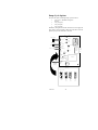
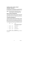
ICE MAKER
POCKET GUIDE
“I” SERIES CUBE
ICE MAKERS
IMI CORNELIUS
One Cornelius Place
Anoka, MN 55303
1–800–238–3600
TD 204(Metric)
TABLE OF CONTENTS
PAGE
introduction . . . . . . . . . . . . . . . . . . . . . . . . . . . . . . . . . . . . . .
1
Original Owner, End-user responsibility . . . . . . . . . . . .
1
Serial Plate Locations . . . . . . . . . . . . . . . . . . . . . . . . . . . . . .
2
Model and Serial Number Defined . . . . . . . . . . . . . . . . . . . .
2
Serial Number Defined After January 1, 1995 . . . . . . . . . .
3
Electrical Specification . . . . . . . . . . . . . . . . . . . . . . . . . . . . . 4-9
Remote Condenser . . . . . . . . . . . . . . . . . . . . . . . . . . . . . . . . . 10
ICE CAPACITY INFORMATION . . . . . . . . . . . . . . . . . . . 11
Ice Capacity . . . . . . . . . . . . . . . . . . . . . . . . . . . . . . . . . . . . . . 11
Ice Production Check . . . . . . . . . . . . . . . . . . . . . . . . . . . . . . 11
ADJUSTMENT OF ICE BRIDGE THICKNESS . . . . . . . . 12
Ice production capacities and charts . . . . . . . . . . . .
14-29
IAC322/IAC330 . . . . . . . . . . . . . . . . . . . . . . . . . . . . . .
14
IWC322/IWC330 . . . . . . . . . . . . . . . . . . . . . . . . . . . . .
15
IAC522/IAC530 . . . . . . . . . . . . . . . . . . . . . . . . . . . . . .
16
IWC522/IWC530 . . . . . . . . . . . . . . . . . . . . . . . . . . . . .
17
IAC630 . . . . . . . . . . . . . . . . . . . . . . . . . . . . . . . . . . . . .
18
IWC630 . . . . . . . . . . . . . . . . . . . . . . . . . . . . . . . . . . . .
19
IRC630 . . . . . . . . . . . . . . . . . . . . . . . . . . . . . . . . . . . . .
20
IAC830 . . . . . . . . . . . . . . . . . . . . . . . . . . . . . . . . . . . . .
21
IWC830 . . . . . . . . . . . . . . . . . . . . . . . . . . . . . . . . . . . .
22
IRC830 . . . . . . . . . . . . . . . . . . . . . . . . . . . . . . . . . . . . .
23
IAC1230 . . . . . . . . . . . . . . . . . . . . . . . . . . . . . . . . . . . .
24
IWC1230 . . . . . . . . . . . . . . . . . . . . . . . . . . . . . . . . . . .
25
IRC1230 . . . . . . . . . . . . . . . . . . . . . . . . . . . . . . . . . . . .
26
IAC1448 . . . . . . . . . . . . . . . . . . . . . . . . . . . . . . . . . . . .
27
IWC1448 . . . . . . . . . . . . . . . . . . . . . . . . . . . . . . . . . . .
28
IRC1448 . . . . . . . . . . . . . . . . . . . . . . . . . . . . . . . . . . . .
29
Sequence of Operation . . . . . . . . . . . . . . . . . . . . . . . . . . . . . . 30
Component Functions . . . . . . . . . . . . . . . . . . . . . . . . . . . . . . 30
Circuit Board . . . . . . . . . . . . . . . . . . . . . . . . . . . . . . . . . . . . . 30
LED Indicators . . . . . . . . . . . . . . . . . . . . . . . . . . . . . . .
31
LED status indicator chart . . . . . . . . . . . . . . . . . . . .
32-34
Reset Operation . . . . . . . . . . . . . . . . . . . . . . . . . . . . . .
34
Voltage Selector Switch . . . . . . . . . . . . . . . . . . . . . . . .
34
Stacking Cable . . . . . . . . . . . . . . . . . . . . . . . . . . . . . . .
34
Test Plug . . . . . . . . . . . . . . . . . . . . . . . . . . . . . . . . . . . .
34
Dump Cycle Options . . . . . . . . . . . . . . . . . . . . . . . . . .
35
Condenser Fan Cycling Control (Intergal Condenser) .
36
Harvest Safety Termination . . . . . . . . . . . . . . . . . . . . .
36
Circuit Board Diagnosis . . . . . . . . . . . . . . . . . . . . . . . .
36
i
TD 204
TABLE OF CONTENTS (CONT’D)
PAGE
Sensors . . . . . . . . . . . . . . . . . . . . . . . . . . . . . . . . . . . . . . . . . . 37
Sensor [Thermistor] Diagnosis . . . . . . . . . . . . . . . . . . . . . . . 38
Evaporator Switches . . . . . . . . . . . . . . . . . . . . . . . . . . . . . . . 39
Switch Notes . . . . . . . . . . . . . . . . . . . . . . . . . . . . . . . . . . . . . . 39
Voltage Checks . . . . . . . . . . . . . . . . . . . . . . . . . . . . . . . . . . . . 39
Water Regulating Valve . . . . . . . . . . . . . . . . . . . . . . . . . . . . . 40
High Pressure Safety Switch . . . . . . . . . . . . . . . . . . . . . . . . . 40
Float Valve with Flow Washer . . . . . . . . . . . . . . . . . . . . . . . 41
Service Stem Valves . . . . . . . . . . . . . . . . . . . . . . . . . . . . . . . . 41
Thermostatic Expansion Valves . . . . . . . . . . . . . . . . . . . . . . 41
diagnosis . . . . . . . . . . . . . . . . . . . . . . . . . . . . . . . . . . . . . . . . . 42
Starving TXV - Product Symptoms . . . . . . . . . . . . . . . . . . . 42
Flooding TXV - Product Symptoms . . . . . . . . . . . . . . . . . . . 42
Head Pressure Control Valve [Headmaster} Fan Cycle Switch
(Remote Units Only) . . . . . . . . . . . . . . . . . . . . . . 43
Contactor Compressor . . . . . . . . . . . . . . . . . . . . . . . . . . . . . 44
Compressor & Starting Component Check-Out Procedure 45
Relay . . . . . . . . . . . . . . . . . . . . . . . . . . . . . . . . . . . . . . . . . . . . 45
Potential – . . . . . . . . . . . . . . . . . . . . . . . . . . . . . . . . . . .
45
Current – . . . . . . . . . . . . . . . . . . . . . . . . . . . . . . . . . . . .
45
Capacitors . . . . . . . . . . . . . . . . . . . . . . . . . . . . . . . . . . . . . . . 46
Compressor . . . . . . . . . . . . . . . . . . . . . . . . . . . . . . . . . . . . . . 46
Moisture Contamination . . . . . . . . . . . . . . . . . . . . . . . . . . . . 47
Wiring Diagrams . . . . . . . . . . . . . . . . . . . . . . . . . . . .
49-54
Troubleshooting . . . . . . . . . . . . . . . . . . . . . . . . . . . . . . . . . . . 55
Cleaning Procedures . . . . . . . . . . . . . . . . . . . . . . . . . . . . . . . 59
Prep – Cleaning . . . . . . . . . . . . . . . . . . . . . . . . . . . . . . . . . . . 59
Cleaning the Water System & Evaporator . . . . . . . . . . . . . . 59
Sanitizing Procedures . . . . . . . . . . . . . . . . . . . . . . . . . . . . . . 60
TD 204
ii
introduction
This guide is published as an aid to the Service Technician. It is not
intended to replace the service manual. In it you will find useful information not found in the service manual. This information will
help you more quickly identify specific problems, however not all
problems or situations may be listed. We appreciate your comments
or suggestions, or if you have a specific problem not addressed in
this guide or service manual.
Please feel free to contact our service department at:
IMI CORNELIUS
One Cornelius Place
Anoka, MN 55303
1–800–554–3526
The warranty on Cornelius icemakers begins on the date of installation, as reported on the warranty registration card to the original
owner/user. If no warranty card is received by the factory, the date
of shipment from the factory will determine the start of the warranty.
Warranty labor will be paid per the labor rate guide and is subject to
change without notice. Call the Service Department for a copy of the
current Labor Rate Guide and/or applicable Warranty Document
Copy.
ORIGINAL OWNER, END-USER RESPONSIBILITY
1. To verify the equipment installation date by the return
of the warranty registration card to the factory within
five days of the installation.
2. To pay freight or handling charge.
3. To pay for service labor and/or parts required to correct improperly installed equipment. Installation must
comply with the installation instructions.
4. To pay for normal maintenance, adjustments and
cleaning.
5. To pay for service labor and/or parts required to correct unit modification or the use of non-approved remote condensers.
6. To pay for service labor and/or parts required because
of neglect, abuse, misuse, accident, fire, flood, freezing or any act of God.
7. To pay for mileage, truck charges, travel time, premium labor for holidays, weekends or after hours
work, flat rate service call charges, miscellaneous tool
charges, use of diagnostic meters or equipment and all
material not listed on the Warranty Time Rate Guide.
1
TD 204
Serial Plate Locations
Exterior: Left side, Lower Front corner.
Interior: Firewall, Front.
Model and Serial Number Defined
IAC 1230
I
A
C
12
30
Product
Identification
A=Air
Cooled
Condenser
W=Water
Cooled
R=Remote
Cuber
Series
3
5
6
8
10
12
14
30” Wide
Cabinet
22 = 22”
Wide
48 = 48”
wide
94
A
C
E
0000
Year
(the first 2
digits
indicates
year of
production)
Month
Production
Product
Code
Manufacturing
Tracking
Code
Unit
Serial
Number
Month of production code will be:
A = January
G = July
B = February
H = August
C = March
J = September
D = April
K = October
E = May
L = November
F = June
M = December
Note: The letter (I) is not used to avoid being confused with the
number(1)
Product Code:
A = Accessory*
D = Dispenser (motel/hotel)
B = Bin (storage)
E = External condenser (Remote)
C = Cuber
F = Flaker
* Any accessory determined to be required to have a serial number.
TD 204
2
Serial Number Defined
after January 1, 1995
AF
95
01
BC
0000
Eng
change
level
year
Month
Product
Code
Unit
Serial
Number
Engineering change level can be either 1 or 2 digits depending
on the revision level.
Month of production code will be:
01 = January
07 = July
02 = February
08 = August
03 = March
09 = September
04 = April
10 = October
05 = May
11 = November
06 = June
12 = December
Note: The Month must always be 2 digits.
Product Code:
BA = Accessory* BD = Dispenser (motel/hotel)
BB = Bin (storage) BE = External condenser (Remote)
BC = Cuber
BF = Flaker
* Any accessory determined to be required to have a serial number.
3
TD 204
Electrical Specification
MODEL
IAC322/3
30
IWC322/3
30
IAC522/5
30
IWC522/5
30
UNIT
Volts
115
115
115
115
Phase
1
1
1
1
Hertz
60
60
60
60
No. Wires
2+ground
2+ground
2+ground
2+ground
MIN. CIRCUIT
Amps
20
20
20
20
MAX FUSE SIZE (HVAC CIRCUIT BREAKER REQ)
Amps
20
20
20
20
REFRIGERANT
R404a
R404a
R404a
R404a
Type
(HP62)
(HP62)
(HP62)
(HP 62)
Weight
17
15
26
23
(oz)
Weight (g)
482
425
737
652
COMPRESSOR
Volts
115
115
115
115
Phase
1
1
1
1
Hertz
60
60
60
60
LRA
51
51
59
59
RLA
11.5
11.5
11.6
11.6
CONDENSER FAN MOTOR (Air-Cooled System
onlY OR
AIR CIRCULATION FAN MOTOR (Water-Cooled
and Remote Systems only)
Volts
Phase
Hertz
Amps
Running
Watts
WATER PUMP
Volts
Phase
Hertz
Amps
Running
HP
TD 204
115
1
60
115
1
60
115
1
60
115
1
60
1.7
0.38
1.75
0.38
50
6
50
6
115
1
60
115
1
60
115
1
60
115
1
60
0.88
0.88
0.76
0.88
1/40
1/40
1/40
1/40
4
5
TD 204
MODEL
IAC630
IWC630
IRC630
UNIT ELEC.
Volts
230
230
230
Phase
1
1
1
Hertz
60
60
60
No. Wires
2+ground
2+ground
2+ground
MIN. CIRCUIT
Amps
20
20
20
MAX FUSE SIZE (HVAC CIRCUIT BREAKER REQUIRED)
Amps
20
20
20
REFRIGERANT
Type
R404a(HP62)
R404a(HP62)
R404a(HP62)
Weight (oz)
43
35
170
Weight (g)
1219
992
4820
COMPRESSOR
Volts
230
230
230
Phase
1
1
1
IAC830
IWC830
IRC830
230
1
60
2+ground
230
1
60
2+ground
230
1
60
2+ground
20
20
20
20
20
20
R404a(HP 62)
55
1559
R404a(HP 62)
33
936
R404a(HP 62)
170
4820
230
1
230
1
230
1
TD 204
COMPRESSOR (CONT’D)
Hertz
60
LRA
69
RLA
8.8
60
69
8.8
60
69
8.8
60
61
12.5
6
CONDENSER FAN MOTOR (Air-Cooled System only) or
AIR CIRCULATION FAN MOTOR (Water-Cooled and Remote Systems
Volts
230
230
230
230
Phase
1
1
1
1
Hertz
60
60
60
60
Amps Running
1.09
0.36
0.36
1.09
Watts
75
6
6
75
WATER PUMP
Volts
230
230
230
230
Phase
1
1
1
1
Hertz
60
60
60
60
Amps Running
0.5
0.5
0.5
0.5
HP
1/30
1/30
1/30
1/30
60
61
12.5
60
61
12.5
only)
230
1
60
0.36
6
230
1
60
0.36
6
230
1
60
0.5
1/30
230
1
60
0.5
1/30
7
TD 204
MODEL
IAC1230
IWC1230
IRC1230
UNIT ELEC.
Volts
230
230
230
Phase
1
1
1
Hertz
60
60
60
No. Wires
2+ground
2+ground
2+ground
MIN. CIRCUIT
Amps
20
20
20
MAX FUSE SIZE (HVAC CIRCUIT BREAKER REQUIRED)
Amps
20
20
20
REFRIGERANT
Type
R404a(HP62)
R404a(HP62)
R404a(HP62)
Weight (oz)
49
45
210
Weight (g)
1389
1276
5954
COMPRESSOR
Volts
230
230
230
Phase
1
1
1
IAC1448
IWC1448
IRC1448
230
1
60
2+ground
230
1
60
2+ground
230
1
60
2+ground
25
25
25
25
25
25
R404a(HP 62)
92
2608
R404a(HP 62)
44
1247
R404a(HP 62)
250
7088
230
1
230
1
230
1
TD 204
COMPRESSOR (CONT’D)
Hertz
60
LRA
96
RLA
13.5
60
96
13.5
60
96
13.5
60
95.6
23.9
8
CONDENSER FAN MOTOR (Air-Cooled System only) or
AIR CIRCULATION FAN MOTOR (Water-Cooled and Remote Systems
Volts
230
230
230
230
Phase
1
1
1
1
Hertz
60
60
60
60
Amps Running
0.89 X 2
0.36
0.36
0.4
Watts
50 W X 2
6W
6W
1/15 HP
WATER PUMP
Volts
230
230
230
230
Phase
1
1
1
1
Hertz
60
60
60
60
Amps Running
0.5
0.5
0.5
0.5
HP
1/30
1/30
1/30
1/30
60
95.6
23.9
60
95.6
23.9
only)
230
1
60
0.36
6W
230
1
60
0.36
6W
230
1
60
0.5
1/30
230
1
60
0.5
1/30
MODEL
IRC630 IRC830. IRC1230 IRC1448
UNIT
Volts
230
230
230
230
Phase
1
1
1
1
Hertz
60
60
60
60
No. Wires
2+ground 2+ground 2+ground 2+ground
MIN. CIRCUIT
Amps
20
20
20
25
MAX FUSE SIZE (HVAC CIRCUIT BREAKER REQUIRED)
Amps
20
REFRIGERANT
R404a
Type
(HP62)
Weight
(oz)
170
20
20
25
R404a
(HP62)
R404a
(HP62)
R404a
(HP 62)
170
210
250
5954
7088
230
1
60
96
13.5
230
1
60
95.6
23.9
230
1
60
230
1
60
0.36
0.36
Weight (g)
4820
4820
COMPRESSOR
Volts
230
230
Phase
1
1
Hertz
60
60
LRA
69
61
RLA
8.8
12.5
AIR CIRCULATION FAN MOTOR
Volts
230
230
Phase
1
1
Hertz
60
60
Amps
0.36
0.36
Running
Watts
WATER PUMP
Volts
Phase
Hertz
Amps
Running
6
6
6
6
230
1
60
230
1
60
230
1
60
230
1
60
0.5
0.5
0.5
0.5
HP
1/30
1/30
1/30
1/30
9
TD 204
Remote Condenser
MODEL
CR800
CR1200
CR1400
Volts
230
230
230
Phase
1
1
1
Hertz
60
60
60
Amps
1.0
1.0
1.0
Output, HP
1/6
1/6
1/6
Max. fuse size, Amps (HVAC
circuit breaker
required)
20
20
20
TD 204
10
ICE CAPACITY INFORMATION
Ice Capacity
Ice capacity of any ice maker is affected by many operating conditions, such as water and air temperature and location factors. Please
review the capacity tables in this manual for average 24–hour capacity under various conditions.
NOTE: All printed capacity ratings are 10% except 50
HZ units these products have 12% increase in cycle
time and capacity decrease of approximately
17%.All printed capacity ratings are 10% except
50 HZ units these products have 12% increase in
cycle time and capacity decrease of approximately
17%.
Ice Production Check
If air cooled, take air temperature at the intake of the condenser, 2I
from the condenser fins.. Incoming water temperature at the outlet
of the “float” valve.*
Cycle time (CT) = freeze time plus harvest time, in minutes and seconds. 1440 divided by CT = number of cycles per 24 hours.
Measure weight of ice from one cycle in pounds and fractions of a
pound.
Example: Weight/cycle x cycles/day = total production/24 hrs.
Compare to the production tables.
* If water cooled be certain water regulator valve is set to maintain
300/310 PSI (20.68/21/37 Bars) head pressure.
11
TD 204
ADJUSTMENT OF ICE BRIDGE
THICKNESS
TOP ROW
.95 CM - 1.59 CM
DIMPLE
CENTER
.32 CM BRIDGE
BOTTOM 2 ROWS
.48 CM - .64 CM BRIDGE
For optimum ice production and maximum cube separation, the ice
connecting the individual cubes should be a minimum of 1/8”
(.32cm) thick at the center area of the ice waffle.
BRIDGE 1/8I (0.32 CM)
It is normal for the ice slab to be slightly thicker at the bottom and
taper off in a slight wedge pattern at the top. The top row of cubes
must have a complete pattern of ice on all four sides and the back
wall. Remember, when you operate the product with the panels off
during testing the additional heat at the top of the evaporator will
cause thinner ice at the top than when the panels are in place.
TD 204
12
Should a different thickness of the bridge be desired, it will be required to adjust the ice thickness “POT”, located on the circuit
board, as follows:
1. Thinner Bridge – turn the ice thickness “pot” adjustment screw
CW one full turn. Allow two cycles
before determining if additional adjustments are required.
2. Thicker Bridge – turn the ice thickness “pot” adjusting
screw CCW one full turn. Allow two cycles before
determining if additional adjustments are required.
NOTE: Never judge the thickness of the ice from the first
batch of the ice produced – the first cycle is a balance cycle. Always wait for the second cycle before
making any adjustments.
13
TD 204
TD 204
IAC322/IAC330
FREEZE CYCLE
HARVEST CYCLE
14
CYCLE
TIME
Min:Sec
HEAD
PRESSURE
kPa
SUCTION
PRESSURE
kPa
CYCLE
TIME
Min:Sec
AVERAGE
ICE
WEIGHT
kg/Cycle
AVERAGE
ICE
WEIGHT
kg/day
269
9:5
1034
724
1:1
1.1
147
290
12:4
1103
758
0:9
1.1
118
1841
303
14:3
1262
917
0:7
1.1
109
27
1862
310
15.1
1248
896
0.7
1.1
100
21
2062
324
19:8
1372
979
0:6
1.3
91
AMBIENT
TEMP
_C
WATER
TEMP
_C
HEAD
PRESSURE
kPa
SUCTION
PRESSURE
kPa
21
10
1379
27
21
1572
32
21
32
38
IWC322/IWC330
FREEZE CYCLE
HARVEST CYCLE
SUCTION
PRESSURE
kPa
CYCLE
TIME
Min:Sec
HEAD
PRESSURE
kPa
SUCTION
PRESSURE
kPa
CYCLE
TIME
Min:Sec
AVERAGE
ICE
WEIGHT
kg/Cycle
AVERAGE
ICE
WEIGHT
kg/day
15
AMBIENT
TEMP
_C
WATER
TEMP
_C
HEAD
PRESSURE
kPa
21
10
2068
276
12:1
986
710
0:9
1.3
141
27
21
2068
290
15:3
1103
800
1:1
1.3
111
32
21
2068
296
16:2
1103
814
1:2
1.3
109
32
27
2089
303
16.4
1193
827
1.1
1.3
104
38
21
2068
303
16:3
1103
807
1:3
1.2
98
TD 204
TD 204
IAC522/IAC530
FREEZE CYCLE
HARVEST CYCLE
SUCTION
PRESSURE
kPa
CYCLE
TIME
Min:Sec
HEAD
PRESSURE
kPa
SUCTION
PRESSURE
kPa
CYCLE
TIME
Min:Sec
AVERAGE
ICE
WEIGHT
kg/Cycle
AVERAGE
ICE
WEIGHT
kg/day
16
AMBIENT
TEMP
_C
WATER
TEMP
_C
HEAD
PRESSURE
kPa
21
10
1517
262
12.5
1069
655
1:0
2.3
245
27
21
1724
290
14.6
1207
765
0.9
2.2
204
32
21
1896
283
17.4
1344
827
0.7
2.3
184
32
27
1999
310
17.9
1379
827
0.6
2.3
176
38
21
2206
317
20.9
1517
827
0.6
2.4
159
IWC522/IWC530
FREEZE CYCLE
HARVEST CYCLE
SUCTION
PRESSURE
kPa
CYCLE
TIME
Min:Sec
HEAD
PRESSURE
kPa
SUCTION
PRESSURE
kPa
CYCLE
TIME
Min:Sec
AVERAGE
ICE
WEIGHT
kg/Cycle
AVERAGE
ICE
WEIGHT
kg/day
17
AMBIENT
TEMP
_C
WATER
TEMP
_C
HEAD
PRESSURE
kPa
21
10
2227
303
11:3
1076
731
1:3
1.9
222
27
21
2255
310
13:7
1158
793
1:2
2.0
193
32
21
2248
310
13:8
1193
807
1:1
2.0
191
32
27
2261
324
15:2
1269
876
1:1
2.0
174
38
21
2255
310
13:9
1207
820
1:1
2.0
188
TD 204
TD 204
IAC630
FREEZE CYCLE
HARVEST CYCLE
SUCTION
PRESSURE
kPa
CYCLE
TIME
Min:Sec
HEAD
PRESSURE
kPa
SUCTION
PRESSURE
kPa
CYCLE
TIME
Min:Sec
AVERAGE
ICE
WEIGHT
kg/Cycle
AVERAGE
ICE
WEIGHT
kg/day
18
AMBIENT
TEMP
_C
WATER
TEMP
_C
HEAD
PRESSURE
kPa
21
10
1551
234
8:4
1020
607
1:5
2.4
342
27
21
1800
255
11:3
1145
696
1:2
2.5
290
32
21
2041
276
12:6
1262
779
1:1
2.6
268
32
27
2048
276
13:2
1269
779
1:0
2.5
254
38
21
2296
296
17:1
1379
862
1:1
2.7
215
IWC630
FREEZE CYCLE
HARVEST CYCLE
SUCTION
PRESSURE
kPa
CYCLE
TIME
Min:Sec
HEAD
PRESSURE
kPa
SUCTION
PRESSURE
kPa
CYCLE
TIME
Min:Sec
AVERAGE
ICE
WEIGHT
kg/Cycle
AVERAGE
ICE
WEIGHT
kg/day
19
AMBIENT
TEMP
_C
WATER
TEMP
_C
HEAD
PRESSURE
kPa
21
10
2062
241
10:1
986
593
1:6
2.6
324
27
21
2062
262
12:4
1048
634
1:4
2.7
282
32
21
2068
262
12:3
1055
641
1:4
2.7
281
32
27
2096
269
14:0
1145
689
1:2
2.7
259
38
21
2068
262
12:2
1048
641
1:4
2.6
279
TD 204
TD 204
IRC630
FREEZE CYCLE
HARVEST CYCLE
SUCTION
PRESSURE
kPa
CYCLE
TIME
Min:Sec
HEAD
PRESSURE
kPa
SUCTION
PRESSURE
kPa
CYCLE
TIME
Min:Sec
AVERAGE
ICE
WEIGHT
kg/Cycle
AVERAGE
ICE
WEIGHT
kg/day
20
AMBIENT
TEMP
_C
WATER
TEMP
_C
HEAD
PRESSURE
kPa
21
10
1551
234
8:4
1020
607
1:5
2.4
342
27
21
1800
255
11:3
1145
696
1:2
2.5
290
32
21
2041
276
12:6
1262
779
1:1
2.6
268
32
27
2048
276
13:2
1269
779
1:0
2.5
254
38
21
2296
296
17:1
1379
862
1:1
2.7
215
IAC830
FREEZE CYCLE
HARVEST CYCLE
SUCTION
PRESSURE
kPa
CYCLE
TIME
Min:Sec
HEAD
PRESSURE
kPa
SUCTION
PRESSURE
kPa
CYCLE
TIME
Min:Sec
AVERAGE
ICE
WEIGHT
kg/Cycle
AVERAGE
ICE
WEIGHT
kg/day
21
AMBIENT
TEMP
_C
WATER
TEMP
_C
HEAD
PRESSURE
kPa
21
10
1744
200
7:6
1124
572
1:5
2.4
381
27
21
2020
228
9:0
1289
669
1:0
2.3
338
32
21
2310
248
11:5
1448
765
0:9
2.7
308
32
27
2337
255
12:0
1441
765
0:9
2.6
293
38
21
2613
276
13:8
1600
869
0:8
2.7
270
TD 204
TD 204
IWC830
FREEZE CYCLE
HARVEST CYCLE
SUCTION
PRESSURE
kPa
CYCLE
TIME
Min:Sec
HEAD
PRESSURE
kPa
SUCTION
PRESSURE
kPa
CYCLE
TIME
Min:Sec
AVERAGE
ICE
WEIGHT
kg/Cycle
AVERAGE
ICE
WEIGHT
kg/day
22
AMBIENT
TEMP
_C
WATER
TEMP
_C
HEAD
PRESSURE
kPa
21
10
2055
221
8:6
1062
558
1:5
2.5
361
27
21
2041
234
10:2
1124
593
1:3
2.6
324
32
21
2034
234
10:7
1131
600
1:3
2.7
322
32
27
2055
255
12:1
1145
607
1:2
2.6
295
38
21
2034
234
11:1
1207
641
1:3
2.7
313
IRC830
FREEZE CYCLE
HARVEST CYCLE
SUCTION
PRESSURE
kPa
CYCLE
TIME
Min:Sec
HEAD
PRESSURE
kPa
SUCTION
PRESSURE
kPa
CYCLE
TIME
Min:Sec
AVERAGE
ICE
WEIGHT
kg/Cycle
AVERAGE
ICE
WEIGHT
kg/day
23
AMBIENT
TEMP
_C
WATER
TEMP
_C
HEAD
PRESSURE
kPa
21
10
1744
200
7:6
1124
572
1:5
2.4
381
27
21
2020
228
9:0
1289
669
1:0
2.3
338
32
21
2310
248
11:5
1448
765
0:9
2.7
308
32
27
2337
255
12:0
1441
765
0:9
2.6
293
38
21
2613
276
13:8
1600
869
0:8
2.7
270
TD 204
TD 204
IAC1030
FREEZE CYCLE
HARVEST CYCLE
SUCTION
PRESSURE
kPa
CYCLE
TIME
Min:Sec
HEAD
PRESSURE
kPa
SUCTION
PRESSURE
kPa
CYCLE
TIME
Min:Sec
AVERAGE
ICE
WEIGHT
kg/Cycle
AVERAGE
ICE
WEIGHT
kg/day
24
AMBIENT
TEMP
_C
WATER
TEMP
_C
HEAD
PRESSURE
kPa
21
10
1655
228
13.5
1131
517
1.7
5.3
499
27
21
21903
248
14.2
1220
572
1.4
4.8
440
32
21
2151
262
15.9
1351
627
1.1
4.8
404
32
27
2158
262
16.8
1365
627
1.1
4.7
381
38
21
2406
283
18.7
1482
689
1.0
4.9
360
IWC1030
FREEZE CYCLE
HARVEST CYCLE
SUCTION
PRESSURE
kPa
CYCLE
TIME
Min:Sec
HEAD
PRESSURE
kPa
SUCTION
PRESSURE
kPa
CYCLE
TIME
Min:Sec
AVERAGE
ICE
WEIGHT
kg/Cycle
AVERAGE
ICE
WEIGHT
kg/day
25
AMBIENT
TEMP
_C
WATER
TEMP
_C
HEAD
PRESSURE
kPa
21
10
2041
234
13.0
1069
503
1.8
4.9
474
27
21
2048
241
15.3
1110
517
1.7
4.9
420
32
21
2048
248
15.7
1110
531
1.5
5.0
417
32
27
2068
248
17.9
1207
558
1.4
5.0
373
38
21
2048
248
15.8
1131
531
1.5
5.0
415
TD 204
TD 204
IRC1030
FREEZE CYCLE
HARVEST CYCLE
SUCTION
PRESSURE
kPa
CYCLE
TIME
Min:Sec
HEAD
PRESSURE
kPa
SUCTION
PRESSURE
kPa
CYCLE
TIME
Min:Sec
AVERAGE
ICE
WEIGHT
kg/Cycle
AVERAGE
ICE
WEIGHT
kg/day
26
AMBIENT
TEMP
_C
WATER
TEMP
_C
HEAD
PRESSURE
kPa
21
10
1655
228
13.5
1131
517
1.7
5.3
499
27
21
1903
248
14.2
1220
572
1.4
4.8
440
32
21
2151
262
15.9
1351
627
1.1
4.8
404
32
27
2158
262
16.8
1365
627
1.1
4.7
381
38
21
2406
283
18.7
1482
689
1.0
4.9
360
IAC1230
FREEZE CYCLE
HARVEST CYCLE
SUCTION
PRESSURE
kPa
CYCLE
TIME
Min:Sec
HEAD
PRESSURE
kPa
SUCTION
PRESSURE
kPa
CYCLE
TIME
Min:Sec
AVERAGE
ICE
WEIGHT
kg/Cycle
AVERAGE
ICE
WEIGHT
kg/day
27
AMBIENT
TEMP
_C
WATER
TEMP
_C
HEAD
PRESSURE
kPa
21
10
1593
207
8:8
1207
517
1:5
4.1
567
27
21
21834
228
11:4
1317
579
1:1
4.3
494
32
21
2041
241
13:6
1455
655
1:0
4.6
454
32
27
2034
248
14:5
1455
641
0:9
4.6
430
38
21
2282
262
16:3
1600
724
0:9
4.7
392
TD 204
TD 204
IWC1230
FREEZE CYCLE
HARVEST CYCLE
SUCTION
PRESSURE
kPa
CYCLE
TIME
Min:Sec
HEAD
PRESSURE
kPa
SUCTION
PRESSURE
kPa
CYCLE
TIME
Min:Sec
AVERAGE
ICE
WEIGHT
kg/Cycle
AVERAGE
ICE
WEIGHT
kg/day
28
AMBIENT
TEMP
_C
WATER
TEMP
_C
HEAD
PRESSURE
kPa
21
10
2317
207
10:1
1289
503
1:4
4.4
554
27
21
2234
207
13:2
1220
524
1:3
4.9
483
32
21
2275
228
14:0
1241
524
1:3
5.0
467
32
27
2227
221
14:8
1241
538
1:3
4.9
441
38
21
2234
207
14:0
1241
524
1:3
4.9
465
IRC1230
FREEZE CYCLE
HARVEST CYCLE
SUCTION
PRESSURE
kPa
CYCLE
TIME
Min:Sec
HEAD
PRESSURE
kPa
SUCTION
PRESSURE
kPa
CYCLE
TIME
Min:Sec
AVERAGE
ICE
WEIGHT
kg/Cycle
AVERAGE
ICE
WEIGHT
kg/day
29
AMBIENT
TEMP
_C
WATER
TEMP
_C
HEAD
PRESSURE
kPa
21
10
1593
207
8:8
1207
517
1:5
4.1
567
27
21
1834
228
11:4
1317
579
1:1
4.3
494
32
21
2041
241
13:6
1455
655
1:0
4.6
454
32
27
2034
248
14:5
1455
641
0:9
4.6
430
38
21
2282
262
16:3
1600
724
0:9
4.7
392
TD 204
TD 204
IAC1448
FREEZE CYCLE
HARVEST CYCLE
SUCTION
PRESSURE
kPa
CYCLE
TIME
Min:Sec
HEAD
PRESSURE
kPa
SUCTION
PRESSURE
kPa
CYCLE
TIME
Min:Sec
AVERAGE
ICE
WEIGHT
kg/Cycle
AVERAGE
ICE
WEIGHT
kg/day
30
AMBIENT
TEMP
_C
WATER
TEMP
_C
HEAD
PRESSURE
kPa
21
10
1696
214
10:1
1276
545
1:3
5.5
692
27
21
1931
234
11:8
1386
607
1:3
5.6
615
32
21
2172
241
13:2
1517
669
1:1
5.7
578
32
27
2186
255
13:7
1531
676
1:1
5.6
547
38
21
2427
262
15:8
1669
731
0:8
6.0
517
IWC1448
FREEZE CYCLE
HARVEST CYCLE
SUCTION
PRESSURE
kPa
CYCLE
TIME
Min:Sec
HEAD
PRESSURE
kPa
SUCTION
PRESSURE
kPa
CYCLE
TIME
Min:Sec
AVERAGE
ICE
WEIGHT
kg/Cycle
AVERAGE
ICE
WEIGHT
kg/day
31
AMBIENT
TEMP
_C
WATER
TEMP
_C
HEAD
PRESSURE
kPa
21
10
2179
221
9:9
1241
503
1:7
5.5
683
27
21
2193
241
11:9
1296
531
1:4
5.8
621
32
21
2193
248
12:2
1310
538
1:3
5.8
617
32
27
2186
255
13:0
1338
552
1:3
5.7
576
38
21
2179
248
12:7
1303
531
1:4
5.9
606
TD 204
TD 204
IRC1448
FREEZE CYCLE
HARVEST CYCLE
SUCTION
PRESSURE
kPa
CYCLE
TIME
Min:Sec
HEAD
PRESSURE
kPa
SUCTION
PRESSURE
kPa
CYCLE
TIME
Min:Sec
AVERAGE
ICE
WEIGHT
kg/Cycle
AVERAGE
ICE
WEIGHT
kg/day
32
AMBIENT
TEMP
_C
WATER
TEMP
_C
HEAD
PRESSURE
kPa
21
10
1696
214
10:1
1276
545
1:3
5.5
696
27
21
1931
234
11:8
1386
607
1:3
5.6
619
32
21
2172
241
13:2
1517
669
1:1
5.8
583
32
27
2186
255
13:7
1531
676
1:1
5.7
551
38
21
2427
262
15:8
1669
731
0:8
6.0
522
“I” SERIES
SEQUENCE OF OPERATION
When the on off clean switch is pushed to the on position the compressor will start after a 2 second delay. The fan motor and pump are
delayed. The condenser fan motor on integral air cooled unites will
start when the condenser temperature rises to approximately 38° C.
The water pump will start when the suction line temperature reaches
approximately –4°C. Temperature information is transmitted to the
control board thru thermistor sensors. The unit is now in the freeze
cycle. If after approximately 6 minutes of operation the suction line
temperature is not below 4.4°C, the unit will shut down and show an
error light on the control board. When the harvesting set point temperature is reached, the circuit board will switch to the harvest cycle.
At the start of the harvest cycle the condenser fan motor will shut off
and the Dump Valve and Hot Gas Valve will open. The Water Pump
will shut down in approximately 15 seconds. Harvest will continue
for approximately 90 seconds. when the Ice is harvested the evaporator curtain opens and closes breaking a magnetic field of the evaporator proximity switch which signals the circuit board to switch
back to the Freeze Cycle.
When the Evaporator Curtain is held open, in the freeze cycle,
breaking the Evaporator Switch Magnetic Field for 5 to 8 seconds,
the circuit board is signaled that a full bin condition has been
reached , and shuts down the unit.
COMPONENT FUNCTIONS
Circuit Board
The circuit board controls the operation of the Ice Maker through information it receives from Thermistor Sensors and Proximity (magnetic) Switches.
33
TD 204
LED Indicators
The LEDs are board circuit indicators. If the LED in the functional
board circuit is complete, check component.
Example: Contactor does not energize and LED is “ON”, board circuit is OK. Check contactor, coil, leads, & connections.
Yellow;
S
Evaporator switch(s) (proximity)
Green;
S
D15 Water dump valve
S
D14 Compressor contactor
S
D12 Water Pump
S
D11 Hot Gas Valve
S
D6 Condenser Fan (cycles on &
off with fan)
Red D5;
Error in system operation. Product shut down.
Water
Dump
Valve
DĆ15
DĆ13
YL
RH Evap. Switch
DĆ14
RH Evap.
N
7
Contactor
8
S
Water
Pump
YL
LH Evap. Switch
DĆ10
DĆ12
5
6
3
4
1
N
2
LH Evap.
S
Hot Gas
GR
Condenser Sensor
white
Condenser
plug
DĆ11
230v
Suction Line Sensor
Suction plug
Voltage
Selector
Switch
Fan
Brown
DĆ6
Test
Plug
RD
GR
DĆ5
115v
Error
Options
Plug
Adjustable Ice
Thickness Pot.
Transformer
Micro Processor
Stacking
Cable
Plug
To Stacked
Unit
(if required)
TD 204
neutral
Manual
Harvest
Switch
34
LED STATUS INDICATOR CHART
D6
D10
D11
D12
D13
D14
D5
D15
Green LED
Condenser Fan
Yellow LED
Left Water Curtain
Green LED
Hot Gas Valve
Green LED
Water Pump
Yellow LED
Right Water Curtain
Green LED
Compressor Contactor
Red LED
Error
Green LED
Dump Valve
Curtain Open
D13
Yellow LED
Off
Right evaporator curtain
open
D10
Yellow LED
Off
Left evaporator curtain open
Pre-Chill Mode
D6
Green LED
(on or
off)
Condenser fan cycles on &
off depending upon conĆ
denser temperature
D14
Green LED
(on)
Compressor contactor acĆ
tive - Compressor running
D13
Yellow LED
(on)
Right evaporator curtain
closed
D10
Yellow LED
(on)
Left evaporator curtain
closed (only if unit has two
evaporators)
D6
Green LED
(on or
off)
Condenser fan cycles on
and off depending upon
condenser temperature
D12
Green LED
(on)
Water pump active
D14
Green LED
(on)
Compressor contactor acĆ
tive - compressor running
D13
Yellow LED
(on)
Right evaporator curtain
closed
D10
Yellow LED
(on)
Left evaporator curtain
closed (only if unit has two
evaporators)
Ice Making Mode
Continued on page 36
35
TD 204
Harvest Mode
D11
Green LED
(on)
Three seconds after water
dump valve becomes acĆ
tive, the hot gas valve beĆ
comes active
D12
Green LED
(on)
15
sec.
Fifteen seconds after water
dump valve becomes acĆ
tive, the water pump deactiĆ
vates
D14
Green LED
(on)
Compressor contactor acĆ
tive - compressor running
D15
Green LED
(on)
15
sec.
Water dump valve becomes
active at the start of harvest.
Water dump valve is active
for 15 seconds
D13
Yellow LED
(on)
Right evaporator curtain
closed. When the ice falls
and the curtain opens the
LED will turn off.
D10
Yellow LED
(on)
Same as D13 if there is a
second (left) evaporator
D5
Red LED
(on)
EVAPORATOR OPEN
THERMISTOR CIRCUIT Ć
thermistor open / broken
wire / poor connection. Ice
maker is SHUT DOWN.
Consult service manual
(Diagnostic Section) for
trouble shooting guide.
D5
Red LED
(on)
EVAPORATOR HIGH TEMP.
ERROR: Six minutes into the
Freeze cycle the suction line
temperature failed to reach
4.4°C or below. Ice Maker is
SHUT DOWN. Consult serĆ
vice manual (Diagnostic
Section) for trouble shooting
guide.
D5
Red LED
(on)
TWO REPEATED FAILED
HARVEST CYCLES Ć No ice
drop.
Error LED
Continued on page 37
TD 204
36
Error LED (cont’d)
D5
Red LED
FlashĆ CONDENSER OPEN
ing,
THERMISTOR CIRCUIT (Air
1/sec Cooled only) Ć Thermistor
open / broken wire / poor
connection. Ice Maker is
SHUT DOWN. Consult serĆ
vice manual (Diagnostic
Section) for trouble shooting
guide.
D5
Red LED
FlashĆ CONDENSER LOW TEMĆ
ing,
PERATURE CONDITION. Ć
1/sec Condenser midpoint reachĆ
es 2.2°C Ć Ice Maker is
SHUT DOWN.
D5
Red LED
FlashĆ CONDENSER HIGH TEMĆ
ing,
PERATURE SAFETY SHUT
1/sec DOWN
Reset Operation
When Cuber is functionally shut down and red “Error LED” is operational, the Cuber power switch must be turned off for 5 seconds
and returned to the on position to reset the circuit board and allow
the Cuber to restart operation.
Voltage Selector Switch
1.
Selector bar in center position, switch is open. Product
is inoperative
2.
Selector bar in down position, selection is for 115
VAC.
3.
Selector bar in up position, selection is for 230 VAC.
Stacking Cable
When stacking the “I” series cuber the connecting cable (connecting
the two (2) circuit boards) will allow: When the bottom product
shuts off on the full bin signal (or any error code) the top product will
finish the cycle it is in and will also shut down. The “I” series should
never be stacked more than two high.
Test Plug
Board manufactures check point.
DO NOT ATTEMPT ANY VOLTAGE CHECKS AT THESE PINS.
37
TD 204
Dump Cycle Options
You have the option of selecting dump cycle intervals of:
S
every cycle; (Standard setting from
factory)
S
every 3rd cycle;
S
every 5th cycle;
S
every 7th cycle.
Remember, the higher the mineral content in the water supply the
more often it will be required to dump the water and/or clean the
product if proper water treatment is not used.
DĆ15
Water
Dump
Valve
DĆ14
Contactor
DĆ13
YL
RH Evap. Switch
N
S
RH Evap.
Water
Pump
YL
LH Evap. Switch
DĆ10
N
S
7
DĆ12
8
5
6
3
4
1
2
LH Evap.
Hot Gas
GR
Condenser Sensor
white
Condenser
plug
DĆ11
Suction plug
Fan
Suction Line Sensor
230v
Brown
Voltage
Selector
Switch
DĆ6
Test
Plug
RD
GR
115v
DĆ5
Error
Options
Plug
Adjustable Ice
Thickness Pot.
Transformer
Micro Processor
Stacking
Cable
Plug
To Stacked
Unit
(if required)
Manual
Harvest
Switch
Options Plug
Sleeve Connector
Dump
Every
Cycle
TD 204
Dump
Every
3rd
Cycle
38
neutral
Dump
Every
5th
Cycle
Dump
Every
7th
Cycle
Condenser Fan Cycling Control
(Intergal Condenser)
The condenser fan on air-cooled cubers is cycled by the circuit
board. The condenser sensor signals the circuit board when the condenser temperature reaches 100°F (38°C) the fan starts and continues to run until the temperature is reduced to 88°F (31°C).
NOTE: There is no pressure control used to cycle the fan
motor on Intergal Air Cooled Condenser Units.
Harvest Safety Termination
After 4 minutes in the harvest mode, the safety timer in the circuit
board will terminate the harvest mode and place the Cuber back into
a freeze mode. This safety cycle will protect the evaporator etc.
should the product fail to terminate the harvest mode for any reason.
Circuit Board Diagnosis
Turn the power switch off, center position. Disconnect the proximity switches and thermistors from the circuit board. Remove a sleeve
jumper from the options terminal and place it on terminals 4 and 5
(bottom 2 pins) of the test plug (See illustration on page 40). Turn
the power switch to the “on” position and immediately remove the
sleeve jumper from terminals 4 and 5. The LED indicators will cycle
“on” for approximately 2 seconds each in the following sequence.
1.
Red
D-5
(error)*
*Will only cycle if ice thickness
(pot) is within factory setting
2.
Green
D-6
(Condenser fan)
3.
Green
D-11
(hot gas valve)
4.
Green
D-12
(water pump)
5.
Green
D-14
(relay-contractor)
6. Green
D-15
(dump valve)
Failure of the LED’s to cycle in this sequence will signal a defective
circuit board.
39
TD 204
Water
Dump
Valve
DĆ15
DĆ13
YL
RH Evap. Switch
N
S
DĆ14
Contactor
7
RH Evap.
YL
DĆ10
LH Evap. Switch
N
S
Water
Pump
DĆ12
8
5
6
3
4
1
2
LH Evap.
Hot Gas
GR
Condenser Sensor
white
Condenser
plug
DĆ11
Suction plug
Fan
Suction Line Sensor
230v
Brown
Voltage
Selector
Switch
DĆ6
Test
Plug
RD
GR
neutral
115v
DĆ5
Error
Options
Plug
Adjustable Ice
Thickness Pot.
Transformer
Micro Processor
Stacking
Cable
Plug
To Stacked
Unit
(if required)
Manual
Harvest
Switch
Sensors
Condenser sensor (white) and suction line sensor (brown) are
thermistors rated 1k ohm at room temperature.
S
Condenser sensor signals the circuit
board for fan cycling and also serves
as the high temperature safety shut
down. The red “Error LED” will flash
on and off every second, during high
temperature safety shut down. Product is functionally shut down. Reset
procedure must be performed to restart product operation.
S
Suction line sensor signals the circuit
board the suction line temperature, to
control ice bridge thickness. Also the
sensor serves as suction line high
temperature signal (Cuber has 6 minutes to reduce suction line temperature to 40°F (4.4°C) in the freeze
mode). The red “Error LED” will be
steady on ...should this time frame not
be met, product is functionally inoperative during this safety shut down.
Reset procedure must be performed
to restart product operation.
TD 204
40
Sensor [Thermistor] Diagnosis
Sensors
Condenser or suction line – Turn Cuber power switch OFF. Disconnect sensor plug from board. Use digital multimeter set for D.C.
Voltage. Turn power switch ON connect leads of meter across the
two pins of the sensor being checked, meter should read 2.5
VDC0.2 output voltage from the board. If voltage is not correct,
replace the circuit board.
Should the cuber operation indicate there may be a fault
in the sensor [thermistor] or the control board circuit proceed as follows.
1.
Using a good multimeter check the control board sensor output voltage.
2.
Voltage checks are correct proceed:
a.
Disconnect the suction line sensor (brown lead)
from the control board.
b.
Install the special test cord* to the control board
and reinstall the sensor to the test cord terminals.
c.
Connect the multi-meter (set on VDC - millivolts) to the test cord leads.
d.
Operate the cuber in the freeze cycle.
3.
As the suction line temperature decreases the Millivolt reading will increase.
4.
Sensor Shorted - milli-volt reading will cease to increase and will remain steady indicating a shorted sensor.
5.
Sensor Open - The voltage reading will indicate the
control board output voltage of 2.5 VDC.
6.
Should either “4.” or “5.” happen during this test, the
sensor will require replacement.
* Special test cord, part # 164984009, may be ordered
through the Service Department.
7.
Condenser Sensor (white leads) - self-contained air
cooled only - water cooled and remote systems use a
resistor plug on the control board.
Complete the sensor and multi-meter connections as
described in
2- b.,c.,d..
8.
Shorted sensor - a steady low milli-volt reading will
be recorded. The reading will not change.
9.
Open sensor - the multi-meter will record control
board output voltage of 2.5 VDC.
41
TD 204
10.
NOTE:
Should sensor (thermistor) pass the voltage test proceed to the control board diagnosis for LED sequence
(see page 39).
The sensor controls the condenser fan cycling from
88/100 degree Fahrenheit. Thus any defects in the
condenser circuit will effect the fan cycling rate.
Evaporator Switches
Proximity Switches are half mounted to the water curtain, and the
other half mounted to the evaporator side rail. They provide signals
to the control board to allow the board to change cycles from harves
to freeze as well as shut down of the unit in a full bin condition.
Switch Notes
1.
Manually holding the curtain open during freeze
mode, will shut the Cuber down in 5 seconds.
2.
During harvest cycle, if curtain is open for 10 seconds,
the water pump will stop. The compressor will operate
for 20 additional seconds before Cuber shut down
takes place. When the water curtain closed, the Cuber
will begin the normal start-up process.
3.
In single evaporator machines, the proximity switch
connection must be on the top (RH) connection on the
circuit board.
4.
In dual evaporator machines, both RH and LH
switches must open and reset to start the next freeze
mode.
Voltage Checks
Turn Cuber power switch Off. Disconnect proximity switch plug(s)
from the circuit board. Use a digital multimeter set for D.C. Voltage;
turn power switch ON, connect leads of meter across the top two terminal pins on the board, (for the switch being tested), meter should
read 5 VDC ± 0.2 output voltage. If not, replace the circuit board.
Water Regulating Valve
The water regulating valve is used on water–cooled cubers only. The
valve is installed in the condenser outlet water line. It’s function is
to control the proper operating head pressure by regulating the
amount of water flowing through the condenser. The valve is adjustable and factory set to maintain condenser discharge water temperature @ 108/112_F (42-44_C). Setting the water regulating valve to
Continued on page 42
maintain discharge water temperature eliminates the need to enter
the sealed refrigeration system. When checking the valve, the water
temperature should be taken as close to the condenser discharged as
possible. The water temperature will equate to operating head pressure of approximately 310 PSI (21.1 BAR).
TD 204
42
Should adjustment be required, the valve has an adjustment stem on
the top of the valve. After allowing the cuber to operate for 10 minutes in the ice making mode to balance the system, turning the adjusting stem CW
will increase the discharge water temperature,
will decrease the discharge water temperature.
and CCW
The water regulating valve must close off condenser water flow
completely during the “hot gas” harvest cycle. There should be no
discharge water flowing out of the condenser during the harvest
cycle. Should the valve fail to close during the harvest mode, the
condenser will continue to condense the compressor discharge vapor needed for the harvest cycle and this will result in long harvest
times.
Leaking (by–passing) water regulating valves are normally the result of scale build–up on the valve diaphragm and the valve should
be flushed, not replaced. To flush the valve, open the adjusting stem
wide open CCW (or force the valve spring up with a screwdriver),
open and close the water supply to the condenser resulting in the
flushing action. Should this not correct the problem replace the
valve diaphragm. This can be done without entering the sealed refrigeration system.
Damage to the water regulating valve may also be caused by water
hammer. Water hammer will result from the condenser inlet and outlet water lines being reversed or defective valve stops in the water
supply line. Proper installation of water cooled equipment should always include an anti–water hammer standpipe in the supply inlet
line as close to the cuber as possible.
High Pressure Safety Switch
All water-cooled and remote products contain a high pressure safety
cut-out switch. The function of this switch is to shut down the cuber
should excessive pressure develop in the high side of the refrigeration system. This switch will open the power supply at 450 PSI
(30.61 BAR) high side pressure. Should this control open, it must be
reset manually and the cause for the increase in pressure determined.
Float Valve with Flow Washer
The Float Valve Maintains the proper water level in the water reservoir.
There is a flow washer in the inlet side of the float assembly that will
control inlet water pressure from 20/120 PSI (1.37/8.16 Bars). This
will prevent float flutter. In low water pressure conditions, 20 PSI
(1.37 Bars) or less, the flow washer may have to be removed from
the float assembly for proper volume.
43
TD 204
Flow control washer flat side up
Service Stem Valves
When closing the service stem valves to remove your gauge and
manifold set always close the high side stem valve first. Following
this procedure will allow the system to “PULL” the refrigerant vapor
from your manifold set to reduce refrigerant loss. When the pressure
has been reduced, close the low side stem valve.
Thermostatic Expansion Valves
The following suggestions for diagnosis of automatic Thermostatic
Expansion Valve (TXV) are given with the understanding the following have been checked and are correct and/or have been corrected prior to proceeding.
1.
The condenser and fan blade are clean and have proper operating conditions.
2.
Water supply to the product is correct and flow over
the evaporator is correct.
3.
Cuber refrigerant charge is correct.
4.
TXV sensing bulb is properly located and secured to
the suction line and correctly insulated.
5.
Hot gas valve(s) are not leaking and/or weeping
through.
TD 204
44
DIAGNOSIS
Starving TXV - Product Symptoms
1.
Suction pressure lower than normal for the operating
conditions.
2.
Ice production lower than normal and/or none.
3.
Ice pattern on evaporator (if any) thin at top and thick
at bottom.
Flooding TXV - Product Symptoms
1.
Ice production lower than normal and/or none.
2.
Suction pressure stabilizes at higher than normal pressure for operating conditions. Suction pressure does
not modulate and may start to slowly rise.
3.
Ice pattern will be very heavy at the bottom and thin at
the top of the evaporator. Product may not enter harvest cycle because of higher than normal suction line
temperature.
Important: Frost on the suction line may be normal on medium temperature refrigeration equipment. Frost
should be considered a red flag, long run times
will normally produce some type of frost pattern..
Before checking the sealed refrigeration system,
the external conditions that could lead to frost
follow:
1.
Dirty condenser
2.
Dirty condenser fan blade
3.
Improper air clearance around Cuber
4.
Loose TXV bulb mount
5.
Poor water flow over evaporator
6.
Ventilation problems
The expansion valves used on Cornelius “I” series ice equipment
have special super heat settings and bulb charge designed from the
product load and HP 62 refrigerant. Should the need arise to replace
this or any refrigerant components, be certain to use only components recommended by Cornelius for the model of the Cuber being
serviced. Use of nonapproved components will compound system
difficulties and may void product warranty.
45
TD 204
Head Pressure Control Valve
[Headmaster]/Fan Cycle Switch
(Remote Units Only)
receiver
discharge
condenser
above 70°F
normal
receiver
discharge
condenser
below 70°F by-pass
The Cornelius “I” series remote systems use an Alco Head Pressure
Control, normally referred to as a headmaster. This control is
mounted in the remote condenser with a fan cycling control switch.
Using both these controls gives the system positive operation under
a wide range of condensing temperatures.
The fan cycling switch starts the fan at 270 PSI (18.62 Bars) and stop
it at 205 PSI (14.13 Bars) allowing a positive efficient operation at
the high temperature operating ranges.
The headmaster controls the operation when the condensing temperature drops below 21.1°C. The “I” series refrigerant charge is
HP - 62 [R - 404A] and the headmaster dome charge setting is 200
PSI (13.79 Bars) of nitrogen pressure making it stable under the low
temperature operating range down to - 29°C. (Continued on page
46).
The normal flow pattern through the headmaster is from the condenser port to the receiver port. When this flow pattern is unable to
TD 204
46
maintain a receiver outlet pressure equal to or above the dome pressure setting of the valve the dome pressure will force the valve portage to change closing the condenser port and opening the bypass
port from the compressor discharge line. This allow the high pressure vapor from the discharge port to “buck” the receiver pressure
back up. With the condenser port closed, the refrigerant is backed up
in the condenser, basically reducing the condenser size, assisting in
maintaining the discharge portage flow and increasing the head
pressure.
Remember, sense of touch to the lines of the headmaster will determine the flow path the headmaster is in, condenser to receive or bypass to receiver.
High side gauge installed at the receiver outlet valve will determine
if the headmaster is functioning to maintain the proper operating
pressure.
In the event the control appears to be “stuck in bypass”, the pressure
drop across the headmaster must be measured. With a gauge
installed at the receiver outlet valve and the high side service valve,
the pressure difference at these two points must be less the 15 PSI
(1.03 Bars). Three most common causes of an excessive pressure
drop are shortage of refrigerant, kinked remote lines, and excessive
line length.
Eliminate refrigerant shortage first. Add refrigerant in two pound increments (not to exceed six pounds) to determine if it corrects the
pressure drop. If pressure drop is not corrected, inspect line set for
sharp bends or kinks, correct as required. If adding refrigerant does
not correct continued (bypass) condition and line set is not damaged, replace headmaster.
Contactor Compressor
The contactor serves as the voltage supply switch for the compressor circuit. Voltage to the coil of the contactor is supplied by the circuit board.
Check Out:
The two (2)* line supply screws of the contactor should always have
supply voltage present when voltage is on to the product.
The other two (2)* screws (load) should have line voltage when the
contactor is energized. The contactor coil receives its supply voltage
from the circuit board. Should the contactor fail to energize:
Check for supply voltage from circuit board, lead connections to
contactor coil, and ohms value of coil.
* (3) if the product is 3 phase
Compressor & Starting Component
Check-Out Procedure
When compressors fail to start or run properly, it is normally the external electrical supply or the compressor start components that are
47
TD 204
defective. The overload protector, start and/or run capacitor, relay,
circuit board, safety controls, etc.
1.
Check voltage at compressor terminals. NO voltage
will require checking the electrical circuit working
back from the compressor to determine where the voltage supply is interrupted and correct as required. The
load voltage, while compressor is trying to start,
should not be less than 90% of rated required voltage.
Line voltage and wire size effect the life expectancy of the electrical
components, compressor, motor winding, solenoid coils, etc.
Poor line quality voltage will cause many erratic electrical problems. Remember every electrical product, ice machine, dispenser,
walk–in, reach–in, air conditioner, etc. required proper power supply to operate. Be certain when voltage checks are performed that
you are measuring load voltage, not line voltage.
2.
NOTE:
A defective capacitor or start relay may prevent the
compressor from starting. Should the compressor attempt to start, but is unable to do so, or if the compressor hums or trips off on the over protector, check the
following:
For 50 HZ application on dual rated 50/60 HZ models, load voltage while compressor is starting must
not be less than 90% of 50 HZ rating.
Relay
Potential –
For the potential type, contacts are normally closed. The start contacts open by C.E.M.F. generated by the compressor at approximately 80% of the normal operating speed. As the contacts open, only the
start capacitor is removed from the start circuit. Both the start and
run winding and the run capacitor remain in the circuit. This relay
may or may not be directional in mounting.
Current –
For the current type, contacts are normally open. The start contacts
close by the high current draw from the locked rotor condition with
only the run winding in the circuit. As the contacts close, the start
capacitor and the start winding is energized and the compressor
starts. At approximately 80% of its operating speed the current draw
drops off, the relay contacts open removing the start winding and
start capacitor from the circuit. Remember, current relays are directional in their mounting to allow contacts to lift and close.
Capacitors
A quick check is to replace suspected defective capacitors with
known good capacitors being careful to stay within the range for
substitute values. Should those values be unknown, a basic rule for
capacity is: for start capacitors 10% and run capacitors 5% of
TD 204
48
the rating on the defective original capacitor being replaced. Voltage
should always try and be matched, if it cannot be it is acceptable to
increase up to 10% higher than the voltage listed on the capacitor being replaced. NEVER put a capacitor on a product with a voltage
rating lower than the original being replaced. If a capacitor analyzer
is not available, an ohm meter may be used to check a capacitor for
short or open circuits. Set the ohm meter to its highest scale and connect its leads to the capacitor terminals.
1.
With a capacitor, without plate defect, the indicator
should first move to zero (0) and then gradually increase to infinity.
2.
If there is no movement of the ohm meter indicator, an
open circuit is indicated.
3.
If the ohm meter indicator moves to zero (0) and remains there, or on a low resistance reading, a short
circuit is indicated.
4.
Please note this check does not determine if the capacitor will deliver the proper rated MFD/UFD required, it
only shows if the capacitor has shorted or open circuits.
5.
Capacitors that show any signs of leakage of electrolyte, or damage of the can, should be replaced. DO
NOT TEST!
Compressor
1.
2.
Using an ohm meter, check for continuity from compressor terminal C to R and C to S. If the compressor
is hot, wait one (1) hour for compressor to cool and
recheck. An open internal overload protector can
cause a lack of continuity. If continuity cannot be measured through all windings, the compressor must be
replaced.
To check the compressor motor for accidental ground,
perform a continuity check between terminals C, R
and S to the compressor shell or a copper line of the
refrigeration system (do not use a painted surface).
Continuity present, the compressor windings are
grounded and the compressor must be replaced.
If the compressor starts, but trips repeatedly on the overload protector, remember that the overload is both temperature and current activated. Be sure to check; (Continued on page 49).
S
Low voltage
S
Undersized supply lines
S
High head pressure
S
High suction pressure
S
Defective capacitors
49
TD 204
S
S
Compressor mechanical problems
Low Refrigerant Charge
Moisture Contamination
With the major changes in refrigerants in today’s marketplace and
the use of hydroscopic oils the control of moisture and contaminates
have become more critical to safeguard against than ever before in
the history of mechanical refrigeration.
Contaminates are also the most difficult of all problems to determine. A Meg–Ohm meter “Megger” can be a valuable tool to aid in
the analysis of this problem. A Meg–Ohm reading log may be
started any time after 90 days of operation of the product. To perform the test, proceed as listed.
Disconnect all three (3) compressor leads, take a Meg-Ohm meter
reading from each compressor terminal to a good chassis ground.
Compare reading to chart below:
Meter
Compressor
Maintenance Required
Reading
Condition
Meg-Ohm
Okay
None needed.
100 -
∞
50 to 100
20 to 50
Moisture present
Severe moisture &
possible contaminated
oil with acid present
.5 to 20
System has severe
contamination
(Continued on page 51).
TD 204
50
Replace drier.
Replace drier with acid
hold type. Run 24
hours, change to regular drier.
Remove compressor
oil and refrigerant
charge. Evacuate,
install liquid and suction line driers (acid
hold type). Recharge
with new oil and refrigerant. Run 24
hours. Discharge system, discard suction
line drier, replace the
liquid line drier. Evacuate and recharge.
Readings in the range listed below 100 Meg–Ohm would be an indicator that the system being tested may have a contamination problem. Where does the problem come from? As an example, the filter
drier may become saturated and hold large percentages of moisture
and the system function without a problem until such time as the
product operating conditions change. Should the room temperature
increase, or the condenser plug–up etc., the higher operating pressures and temperatures may cause the drier filter to release a portion
of it’s held moisture. It is also imperative to avoid opening the sealed
refrigeration system whenever possible and when it is done to be
certain the true problem is correctly diagnosed and repaired. Remember, service gauge sets should only be installed after all external
checks have been performed.
Caution:Megger checks should NEVER be performed
on any compressor that is under a vacuum.
51
TD 204
WH
COMPRESSOR
GR
START
COMPRESSOR
CAPACITOR
CONTACTOR
BK
RD
BR
243-292 mfd
R
115 VAC
C
S
BK
YL
BK
EXTERNAL
COMPRESSOR
M
WH
OVERLOAD
UNIT
OR
BR
SWITCH
BK
BL
1
2
2
5
POTENTIAL
CONDENSATION
FAN (W/C ONLY)
START RELAY
1
WH
3
MANUAL RESET
HIGH PRESSURE
CONTROL(W/C ONLY)
WH
WATER DUMP
BR
VALVE
CO
450 PSIG
WH
BK
BL
BL
WATER DUMP
1
BR
3
SWITCH
2
CONDENSER
FAN MOTOR
(A/C ONLY)
YL
M
RH Evap.
Switch
N
S
(White Lead)
Condenser
Sensor
See note 1
Suction Line
Sensor
(Brown Lead)
Water
D-15
Dump
GR
Valve
D-13 D-14
YL
Relay
GR
RH Evap.
WH
7
8
5
6
Water
4
3
GR
Pump
1
2
D-12
YL
D-10
D-11
Hot Gas
LH Evap.
Valve
GR
230V
(if required)
BL
WH
RD
Voltage
Selector
Suction
D-6
Switch
Plug
Condenser
GR
Fan
115V
HOT GAS
RD
SOLENOID
M
BL
WATER PUMP
Micro
Processor
Stacking
Cable
Plug
Manual
Harvest
Switch
BL
IAC 322 & IWC 322
NOTE 1: CONDENSER SENSOR USED ONLY ON A/C UNITS.
1.8K ohm RESISTOR USED ONLY ON W/C UNITS.
52
WH
PUMP
CORD
D-5
Error
Options
Plug
Adjustable Ice Transformer
Thickness Pot.
To Stacked
Unit
WH
Condenser
Plug
Test
Plug
BK
BK
IAC 330 & IWC 330
WH
COMPRESSOR COMPRESSOR
GR
RUN
COMPRESSOR
CONTACTOR
BK
BR
BK
RD
RD
R
C
30 mfd
440 VAC
S
YL
BK
72-86 mfd
330 VAC
EXTERNAL
YL
COMPRESSOR
WH
M
OVERLOAD
UNIT
OR
BR
SWITCH
1
2
BK
BL
START
CAPACITOR
CAPACITOR
2
5
POTENTIAL
CONDENSATION
FAN (W/C ONLY)
START RELAY
1
WH
3
MANUAL RESET
HIGH PRESSURE
CONTROL(W/C ONLY)
WH
WATER DUMP
BR
CO
450 PSIG
VALVE
WH
BK
BL
BL
WATER DUMP
1
BR
3
2
SWITCH
CONDENSER
FAN MOTOR
(A/C ONLY)
YL
M
RH Evap.
Switch
N
S
(White Lead)
Condenser
Sensor
Water
D-15
Dump
GR
Valve
D-13
D-14
YL
Relay
8
GR
7
6
5
RH Evap.
Water
4
3
GR
Pump
1
2
D-12
YL
D-10
D-11
Hot Gas
LH Evap.
Valve
230V
GR
Condenser
See note 1 Plug
WH
WH
BL
WH
RD
Voltage
Thickness Pot.
HOT GAS
SOLENOID
M
BL
WATER PUMP
Micro
Processor
Stacking
Cable
Plug
WH
PUMP
CORD
Selector
D-6
Suction
Switch
Plug
GR Condenser
Suction Line
Fan
115V
Sensor
(Brown Lead) Test
RD
Plug
D-5
Transformer
Error
Options
Plug Adjustable Ice
To Stacked
Unit
(if required)
BK
BK
Manual
Harvest
Switch
IAC 522 & IWC 522
BL
IAC 530 & IWC 530
NOTE 1: CONDENSER SENSOR USED ONLY ON A/C UNITS.
1.8K ohm RESISTOR USED ONLY ON W/C UNITS.
53
TD 202
53
RD
LIQUID LINE
SOLENOID
(R/C ONLY)
RD
RD
GR
COMPRESSOR
BK
RD
CONTACTOR
RD
S
35 mfd
YL
250 VAC
YL
OVERLOAD
M
OR
BR
BL
145-174 mfd
370 VAC
EXTERNAL
COMPRESSOR
RD
CRANKCASE
HEATER
(RC ONLY) BK
See note 2
BK
BK
CAPACITOR
RD
R
C
BK
START
CAPACITOR
RD
BR
BK
COMPRESSOR
RUN
COMPRESSOR
BK CONDENSATION FAN
POTENTIAL
(W/C & R/C ONLY)
START RELAY
RD
2
5
1
BR
MANUAL RESET
HIGH PRESSURE CONTROL
(W/C & RC ONLY)
RD
WATER DUMP
BR
RD
VALVE
CO
450 PSIG
BL
WATER DUMP
1
BR
SWITCH
WH
BK
BL
UNIT
3
2
SWITCH
M
YL
BK
BK
CONDENSOR
FAN MOTOR
(A/C ONLY)
Water
D-15
Dump
GR
D-13 D-14 Valve
RH Evap.
Switch
N
S
LH Evap.
Switch
N
S
(White Lead)
Condenser
Sensor
See note 1
Suction Line
Sensor
(Brown Lead)
YL
GR
RH Evap.
Relay
7
5
8
6
Water
Pump
3
1
4
2
GR
D-10
D-12
YL
Condenser
Plug
D-6
Suction
Plug
Test
Plug
GR
HOT GAS
SOLENOID
115V
M
BL
WATER PUMP
Micro
Processor
Stacking
Cable
Plug
Manual
Harvest
Switch
IAC 830, IWC 830 & IRC 830
BL
NOTE 1: CONDENSER SENSOR USED ONLY ON A/C UNITS.
1.8K ohm RESISTER USED ONLY ON W/C & R/C UNITS.
NOTE 2: CAPACITORS USED ON 630 BRISTOL COMPRESSOR:
RUN CAP, 25mfd 440 VAC
START CAP. 161-193mfd 250 VAC
54
WH
PUMP
CORD
Voltage
Selector
Switch
Options
Plug Adjustable Ice Transformer
Thickness Pot.
To Stacked
Unit
(if required)
WH
230V
Condenser
Fan
RD
D-5
Error
BL
RD
RD
LH Evap. D-11 Hot Gas
GR
Valve
WH
IAC 630, IWC 630 & IRC 630
RD
LIQUID LINE
SOLENOID
(R/C ONLY)
RD
RD
GR
COMPRESSOR
BK
BK
COMPRESSOR
S
40 mfd
YL
BK
370 VAC
EXTERNAL
RD
YL
COMPRESSOR
BK
M
RD
BK
2
5
POTENTIAL
FAN (W/C & R/C)
START RELAY
1
MANUAL RESET
HIGH PRESSURE
CONTROL(W/C & R\C)
BK
RD
WATER DUMP
VALVE
CO
450 PSIG
BR
RD
330 VAC
OR
BR
CONDENSATION
189-227 mfd
RD
OVERLOAD
BK
CRANKCASE
HEATER
BL
(RC ONLY)
CAPACITOR
RD
see note 2
R
C
START
CAPACITOR
RD
BR
BK
COMPRESSOR
RUN
RD
CONTACTOR
WH
BK
BL
BR
3
CONDENSOR
WATER DUMP
1
2
FAN MOTORS
SWITCH
(A/C ONLY)
UNIT
M
SWITCH
YL
BK
BK
BK
M
WH
D-15
GR
BL
RH Evap.
Switch
N
S
LH Evap.
Switch
N
S
(White Lead)
D-13
YL
Water
Dump
Valve
D-14
Relay
GR
RH Evap.
GR
D-10
YL
LH Evap.
Condenser Sensor
See note 1
Suction Line
Sensor
(Brown Lead)
D-11 Hot Gas
GR
Valve
Condenser
Plug
7
5
8
6
3
1
4
2
BL
RD
Test
Plug
WH
RD
Voltage
Selector
HOT GAS
SOLENOID
RD
D-5
Error
Transformer
WH
PUMP
CORD
230V
Switch
D-6
Suction
Plug
Condenser
GR
Fan
115V
Options
Plug
To Stacked
Unit
(if required)
Water
Pump
D-12
M
BL
Adjustable Ice
Thickness Pot.
WATER PUMP
Micro
Processor
Stacking
Cable
Plug
Manual
Harvest
Switch
IAC 1230, IWC 1230 & IRC 1230
IAC 1030 IWC 1030 & IRC 1030
BL
NOTE 1: CONDENSER SENSOR USED ONLY ON A/C UNITS.
1.8K ohm RESISTER USED ONLY ON W/C & R/C UNITS.
2: Capacitors used on 103 Compressor
RUN CAP. 37 mfd 370V
START CAP. 145-174 MFD 250v
55
RD
LIQUID LINE
SOLENOID
(R/C ONLY)
RD
RD
GR
COMPRESSOR COMPRESSOR
BK
BK
COMPRESSOR
BK
RD
S
YL
BK
EXTERNAL
M
40 mfd
189-227 mfd
440 VAC
330 VAC
YL
COMPRESSOR
RD
OVERLOAD
RD
SWITCH
CAPACITOR
R
C
UNIT
CAPACITOR
RD
BR
RD
START
RUN
RD
CONTACTOR
OR
BR
CONDENSATION
FAN (W/C & R/C)
BK
BK
2
5
POTENTIAL
BL
1
START RELAY
BK
BR
CRANKCASE HEATER
(A/C & R/C ONLY)
RD
WATER DUMP
VALVE
BL
WATER DUMP
1
BR
CO
450 PSIG
3
2
SWITCH
M
BL
MANUAL RESET
HIGH PRESSURE
CONTROL(W/C & R/C)
RD
WH
BK
BK
YL
WH
BK
CONDENSOR
BR
FAN MOTOR
D-15
Water
Dump
GR
Valve
D-13
D-14
YL GR
RH Evap.
8
Relay
7
Switch
6
5
N
RH Evap.
S
Water
3
4
GR
Pump
1
2
YL
D-12
LH Evap.
D-10
Switch
D-11
N
Hot Gas
LH Evap.
S (White
GR
Valve
230V
Lead)
Condenser Sensor
Voltage
Condenser
See note 1 Plug
Selector
Switch
D-6
Suction
Plug
GR Condenser
Suction Line
Fan
115V
Sensor
Test
(Brown
RD
Plug
D-5
Lead)
Options
Plug
To Stacked
Unit
(if required)
(A/C ONLY)
BL
RD
WH
RD
WH
PUMP
CORD
HOT GAS
SOLENOID
M
BL
Error
WATER PUMP
Adjustable Ice Transformer
Thickness Pot.
Micro
Processor
Stacking
Cable
Plug
Manual
Harvest
Switch
BL
IAC 1448, IWC 1448 & IRC 1448
NOTE 1: CONDENSER SENSOR USED ONLY ON A/C UNITS.
1.8K ohm RESISTER USED ONLY ON W/C & R/C UNITS.
56
WH
CAPACITOR
2 mfd 440 VAC
RED
COLORED
BAND
M
BK
GR
BK
CONDENSOR
FAN MOTOR
HEAT SHRINK TAPE
HEAT
SHRINK
TAPE
RD
FAN CYCLING
SWITCH
BK
RD
RD
GR
HEAT SHRINK TAPE
CR800, CR1200, & CR1400 REMOTE CONDENSERS
208/230 VOLTS 60 HZ
57
TROUBLESHOOTING
IMPORTANT: Only qualified personnel should service internal components or electrical wiring.
Trouble
CUBER NOT
OPERATING
CUBER NOT
OPERATING
INDICATOR
LIGHTS “OFF”,
NO POWER TO
CIRCUIT
BOARD
TD 204
Probable Cause
A. Power
switch in
center “OFF”
position.
A. Test power
switch and
leads.
Remedy
A. Place switch in
“ON” position.
B. High
pressure
cut-out
open. (water
cooled or
remote
systems)
B. Press manual
reset.
Determine
cause:
Water supply
shut off; water
pressure too
low; water valve
defective or out
of adjustment;
water condenser
dirty or corroded;
unit
over-charged;
water inlet
pressure too
high. Replace
defective
component as
needed.
58
A. If defective,
replace.
Trouble
CUBER NOT
OPERATING
INDICATOR
LIGHTS “OFF”,
POWER TO
THE CIRCUIT
BOARD
COMPRESSOR
DOES NOT
RUN, CIRCUIT
BOARD
INDICATOR
LIGHTS “ON”
Probable Cause
Remedy
A. Magnet not
in proximity
switch field.
A. Water curtain
drifting out of
switch range.
Reduce
clearance
between curtain
and proximity
switch.
B. No curtain
movement.
C. Faulty
proximity
switch.
D. Unit “OFF”
due to bin
full.
B. Adjust proximity
switch.
C. Replace
proximity switch.
A. Check
contactor
and leads.
A. Replace if
defective.
B. Compressor
overload
“open”.
B. Permit overload
to cool and reset
or replace.
C. Check
compressor
and start
components.
C. Replace as
needed.
59
D. Remove ice from
curtain.
Eliminate curtain
restriction.
TD 204
Trouble
Probable Cause
COMPRESSOR
RUNS BUT
DOES NOT
COOL, CIRCUIT
BOARD
INDICATOR
LIGHTS “ON”
A. Low charge.
A. Leak check –
Recharge.
B. Hot gas
solenoid
leaking.
B. Replace.
C. Defective
expansion
valve.
C. Replace.
D. Inefficient
compressor.
D. Replace.
E. Internal
by-pass
open,
compressor
noisy.
E. Permit pressures
to equalize.
A. Check
suction line
thermistor
(sensor)
lead wire
connection
at the circuit
board.
A. Tighten,
reattach.
B. Evaporator
thermistor
shorted.
B. Replace.
C. Check
thermistor
(1K ohm).
C. Replace if out of
range.
D. Ice bridge
setting too
low.
D. Adjust per bridge
adjustment
instructions.
CUBER
REMAINS IN
THE FREEZE
CYCLE
TD 204
60
Remedy
Trouble
Probable Cause
E. Expansion
valve failure
(will not pull
down).
CUBER
REMAINS IN
THE HARVEST
CYCLE
Remedy
E. Tighten bulb,
replace as
needed, See
check-out
procedure.
SUCTION LINE THERMISTOR OPEN
(STARTS IN HARVEST)
A. Loose
connection
at the circuit
board.
A. Tighten or
reconnect.
B. Test
thermistor.
B. Replace if out of
range.
PROXIMITY SWITCH LIGHT “OUT”
C. Loose wire
connection
at circuit
board.
C. Tighten, reattach
wire.
D. Proximity
switch
defective,
see
check-out
procedure.
D. Replace as
needed.
E. Water
curtain
stuck,
curtain
frozen to ice
on
evaporator.
Curtain hung
on water
pan,
proximity
switch out of
range.
E. Check and
adjust as
needed.
PROXIMITY SWITCH LIGHT “ON”
61
TD 204
Cleaning Procedures
Approved ice machine cleaners by brand names:
S
Lime-A-Way
S
Calgon Nickel Safe (green color
only)
NOTE: All ice machine cleaners labeled safe for nickel ARE
NOT the brand CALGON NICKEL SAFE.
Caution: Ice machine cleaners are acidic-based chemicals. Before begnning any cleaning of the cuber, the ice in the storage bin or dispenser must
be removed.
Caution: When using any chemical, rubber gloves and
eye protection should be worn.
Prep – Cleaning
Use full-strength ice machine cleaner on a coarse-surface cloth material (such as terry cloth) and wipe down the inside wall of the evaporator area, the water pan, the water curtain and evaporator plastic
extrusions. If the water distributor tube has heavy scale build–up, remove and soak it in full-strength ice machine cleaner (or exchange
the tube and clean the scaled tube at a later date).
Cleaning the Water System &
Evaporator
Power Switch
1.
2.
3.
TD 204
Set the switch to Clean and allow any ice on the evaporator to release and melt away.
Remove all ice from the storage bin.
Remove the water curtain(s), pour 1/2 oz. (14.8 Mil)
of ice machine cleaner down the rear key-slot openings. The cleaner will drain into the water pan.
62
4.
5.
6.
7.
8.
9.
NOTE:
Return the water curtain(s) to their proper operating
position.
Add 88.8 Mil. for a single evaporator, or 147.9 Mil.
for a dual evaporator of “Calgon Nickel-Safe” or
“Lime-A-Away” ice machine cleaner directly into the
water pan the float will balance with inlet water. Set
switch to CLEAN, circulate for a maximum of 15 minutes.
Depress and hold the dump switch to allow the cleaner
to drain away.
Fill the water pan with clean fresh water, circulate for
approximately 3 minutes. Depress and hold the DUMP
switch and allow the water to drain away. Repeat the
procedure 3 times.
After third rinse cycle, place product power switch in
ice position. Allow Cuber to produce one slab of ice –
DISCARD THE ICE.
When the clean cycle is complete, return cuber to normal operating mode.
Please Take Note of the Following:
S
Ice machines should only be
cleaned when needed, not by a
timed schedule of every 60
days, etc.
S
Should your ice machine require cleaning more than twice
a year, consult your distributor
or dealer about proper water
treatment.
Sanitizing Procedures
NOTE:
1.
2.
3.
4.
5.
To be performed only after cleaning the ice machine:
Add 1/4 ounce ( 7.08 Mil) sodium hypochlorite solution (common liquid laundry bleach) to the water pan
and allow the pump to circulate the solution for 5 minutes. You may also use a commercial sanitizer such as
Calgon Ice Machine Sanitizer following the directions
on the product label.
Turn the Cuber power switch off and depress and hold
the dump switch to drain the water pan.
To sanitize the bin and other surface areas, use 1
ounce of liquid bleach per gallon of water and wipe all
areas with the solution. Or use a commercial sanitizer.
Place the Cuber power switch in the ice position. Discard the first batch of ice produced.
Cleaning and sanitizing are now complete. Cuber may
be returned to normal service.
63
TD 204