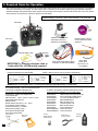
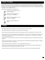
1
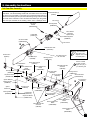
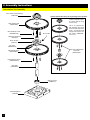
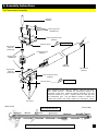
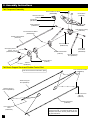
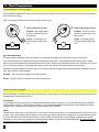
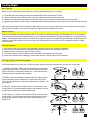
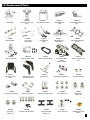
Swift Carbon 620SE
ELECTRIC R/C HELICOPTER
Kit Instruction Manual
Mechanical Specs:
Main Rotor Blades: 600-620mm
Tail Rotor Blades: 75-85mm
Length: 113.3cm
Height: 34.4cm
Weight: 1.76kg (configured with brushless motor and servos)
Electronic Specs:
Speed Control: 50-85 Amp
Motor: 800-1250kv (based on battery)
Battery: 4S-10S Li-Po
Main Gear: 96 Tooth
Pinion: 9-14 Tooth
Head Speed: 1600-2300 RPM
Century Helicopter Products
Designed and Developed in USA
2nd Edition May 2008 All rights reserved.
1. Introduction
Congratulations on your purchase of Century Helicopter Product’s Swift Carbon 620SE Kit. The Swift
Carbon 620SE is a high performance machine providing the agilitiy and durability that is expected out
of a helicopter of this caliber. The attention and praise by the R/C helicopter community is well deserved as the Century Swift line is unmatched in affordability, quality and performance.
In order to take advantage of your Swift’s performance capabilities we recommend using a high quality computer radio system with 120 degree eCCPM mixing. The radio system should have at least 6
channels to use modern heading lock gyros, Standard servos can be used with a specialized high
speed tail servo.
Warning
This radio controlled model is not a toy! It is a precision machine requiring proper assembly and setup
to avoid accidents. It is the responsibility of the owner to operate this product in a safe manner as it
can inflict serious injury otherwise. It is recommended that if you are in doubt of your abilities, seek
assistance from experienced radio control modelers and associations. As manufacturer, we assume
no liability for the use of this product.
Pre-assembly Information
Upon opening the kit, all components are in individual bags. Please thoroughly read through this
manual before attempting assembly. Some specialized tools are recommended but not required for
full assembly.
Be careful when opening each bag as not to lose any hardware. As a reminder, all metal to metal
screw assemblies require “blue” thread lock compound, all metal to plastic screw assemblies require
slow setting CA and all bearing race to metal shafts should use “red” thread lock compound.
Warranty
Your new equipment is warranted to the original purchaser against manufacturer defects in material
and workmanship for 30 days from the date of purchase. During this period, Century Helicopter
Products will repair or replace, at our discretion, any component that is found to be factory defective
at no cost to the purchaser. This warranty is limited to the original purchaser and is not transferable.
This warranty does not apply to any unit which has been improperly installed, mishandled, abused, or
damaged in a crash, or to any unit which has been repaired or altered by any unauthorized agencies.
Under no circumstances will the buyer be entitled to consequential or incidental damages. This limited
warranty gives you specific legal rights. You also have other rights which may vary from state.
Century Helicopter Products
1740-C Junction, Ave.
San Jose, CA 95112
Fax: 408-451-1156
www.centuryheli.com
2
2. Battery Warnings & Safety
Lithium Polymer
Battery Safety
For Lithium Polymer and NiMH/NiCD cell or battery packs purchased.
1.
2.
3.
4.
Never fast-charge any battery type unattended.
Never charge Li-Poly cells or battery packs at any rate unattended.
Only charge Li-Poly cells or battery packs with a charger designed specifically for lithium polymer chemistry.
Li-Poly cells can ignite because of unmatched cell capacity or voltage, cell damage, charger failure, incorrect
charger setting and other factors.
5.
Always use the correct charging voltage. Li-Poly cells or battery packs may ignite if connected to a charger
supplying more than 4.5 volts per cell.
6.
Always assure the charger is working properly.
7.
Always charge Li-Poly cells or battery packs where no harm can result, no matter what happens. We suggest a
brick box or likeness. Have sand handy in a bucket for any need to extinguish any fire. NEVER use water on any
cells or battery packs.
8.
Never charge a cell or battery pack in a model. A hot pack may ignite wood, foam, plastic, etc.
9.
Never charge a cell or battery pack inside a motor vehicle or in a vehicle’s engine compartment.
10. Never charge a cell or battery pack on a wooden workbench or on any flammable material.
11. If a cell or battery pack is involved in a crash:
a. Remove the cell or battery pack from model.
b. Carefully inspect the cell or battery pack for shorts in the wiring or connections. If in doubt, cut all wires from cell
or battery pack.
c. Disassemble the pack
d. Inspect cells for dents, cracks and splits. Dispose of damaged cells.
12. Dispose of cells or battery packs as follows:
a. Discharge: with the cells or battery pack in a safe area, connect a moderate resistance across the terminals until
the cell or battery pack is discharged. CAUTION: cell or battery pack may be hot.
b. Discard:
i. NiMH: place in regular trash
ii. NiCD: recycle (cadmium is toxic)
iii. Li-Poly: puncture plastic envelope, immerse in salt water for several hours and place in regular trash.
13. Handle all cells or battery packs with care, as they can deliver high currents if shorted. Shorting by a wedding ring,
for example, will remove a finger.
14. Always store cells or battery packs in a secure location where they cannot be shorted or handled by children.
15. When constructing a battery pack, always use cells of the same capacity (mAh)
16. DO NOT store fully charged or discharged batteries in your helicopter.
17. When cutting wires, always cut ONLY ONE WIRE AT A TIME.
** Century Helicopter Products will not be liable for any damages that may occur to your helicopter due to any
misuse or mishandling as explained above.
** Century Helicopter Products, its successors, heirs and assignees are not responsible in way for any and all bodily
injuries) and/or property damage that may occur from the use of, or caused by in any way from Lithium Polymer and
NiMH/NiCD cells or battery packs offered by and or distributed by Century Helicopter Products.
3
3. Required Items for Operation
This is the general list of items required to get the Swift Carbon 620 helicopter flying. Century produces a full spectrum of accessories
and tools to assemble your helicopter. The Swift Carbon 620 is a electronic cyclic collective pitch mixing type helicopter requiring a
standard helicopter radio (the helicopter radio requires eCCPM mixing for this model). The Swift Carbon 620 uses 4 servos to operate
critical systems. Gyroscopes are required to operate the model safely.
Necessary Items “Not Included” in the kit.
Transmitter
PG3000 Heading Lock &
Dual Rate Piezo Gyro
#CN2019 (or equivalent)
Servos (4)
Receiver Battery Pack
Brushless Electric Motor
Century Outrunner 600A+
#CNE274
Receiver
Power plant
battery pack
4S-10S Li-Po or
12 Cell NiMH
Electron 80/100 Brushless Speed
Controller w/ Heat Sink #CNE480
IMPORTANT: 6 Channel helicopter radio or
better with 120o eCCPM mixing required.
Fastener and ball bearing dimensions
Hardware Description and Identification:
M3X6 Phillips Machine Screw
M3X6 = 3X6mm and can refer to screws or ball bearings.
M3X6 Self Tapping Screw
M - metric
3 - diameter
6 - length
M3X10 Socket Cap Screw
M3X7x3 Ball Bearing
M - Metric Value
3 - Inside
7 - Outside
3 - Thickness
M - metric
3 - diameter
6 - length
M - metric
3 - diameter
6 - length
WARNING: Do not overtighten bolts or screws possibly damaging threads of bolts or components.
Recommended Tools & Accessories
The tools and materials listed below are
the minimum needed to build the helicopter:
Screwdrivers - Slotted and Phillips head
Long-Nosed Pliers
Allen Wrenches - 1.5mm, 2.0mm, 2.5mm + 3.0mm
Appropriate Socket Wrench
Hobby Scissors
Double Sided Foam Tape ( 1/16” - 3/32” )
Foam Rubber ( Radio Packing )
Thread lock liquid (e.g. Locktite)
Hobby Grease (Super Lube)
Oil to lubricate sliding shafts
CA (Cyanoacrylate) Glue
Hobby scissors
#CN2262
4
Pitch Gauge
#CN2027
In addition, the following will make assembly and setup
easier, and prove useful later in your model toolbox:
Part#CN2015
Part#CN2026
Part#CN2034A Part#CN2052
Part#CN2055
Part#CN2070
Part#CN2219
Part#CN2255
Part#CNWI26555
Part#CNWI26570
Locktite
#CN2025BS blue
#CN2025RS red
Hardened Tip Hex Screw Driver Set
Pitch Gauge with Paddle Gauge
150 Curve Tip Ball link Pliers
Main Blade Balancer
Ball Link Sizing Tool
Universal Flybar Lock
Ball Link Easy Driver
Control Rod Gauge
5.5mm Nut Driver
7.0mm Nut Driver
Needle Nose Pliers & Cutter Pliers
Lubrication
#CN2024T
4. Before You Begin
Every attempt has been made to ease the assembly of your kit, at each step where there are complex instructions there are
detailed written instructions to walk you through each step. Remember to take a few minutes before each step to carefully
examine each process to become familiar with the parts and assembly before beginning that step. All hardware associated
with the part has been bagged and bundled together. When installing a part, make sure to open each bag individually to ease
construction of your Swift Carbon 620SE
D
D
TH
R
EA
R
LO
C
K
TH
R
EA
B
LO
C
K
A
C
Symbols used to help assist you in building the kit:
Whenever this symbol appears, use CA
(cyanoacrylate) glue.
Whenever this symbol appears, use
blue thread lock. (CN2025BS)
Whenever this symbol appears, use red
thread lock. (CN2025RS)
Whenever this symbol appears, use
grease.
OIL
5. Safety
Before flying, please check to make sure no one else is operating on the same frequency.
Before flight, please check if the batteries or transmitter have enough capacity.
Before turning on the transmitter, please check to ensure the throttle stick is in the lowest position. IDLE switch is Off.
When turning on the unit, please follow the power on/off procedure. Power ON - Turn on the transmitter first and then turn
on the receiver. Power OFF - Turn off the receiver first and then turn on the transmitter. If this protocol is not followed,
control of the model may be lost.
Before operation, check movement of all controls are smooth and no linkages are binding. Carefully inspect servos for full
operation.
Check for missing, damaged, or loose items. Carefully inspect main rotor blades and tail blades for damage. If damaged,
replace with new ones to ensure a safe flight.
Check all ball links to ensure proper fitment. If loose, replace ball links with new ones.
Check servo plugs, ESC plugs, motor plugs, gyro plugs, and battery plugs to make sure they are securely fastened. A
loose plug may result in a complete lose of control over the model.
Check the tail belt tension to make sure the belt is not too lose. No more than 5mm movment when pushed inward.
5
6. Assembly Instructions
LO
Cap Screw M4x30
(CNM4x30)
TH
R
EA
D
B
C
K
Main Blade Grip
Cap Screw M3X16
(CNM3x16)
Attaches to feathering
shaft on the following page
*Raised lip should
be facing the bearing
Bearing 3X6x2.5
(CNBB364)
Brass Spacer M3X5x3
(CNE524)
Spacer M3X5x2
(CNE524)
CNC Machined Bell Mixer
(CNE558S)
Add a small
amount of
Synthetic Hydro
Carbon Grease
TH
R
EA
D
Bearing 8x14x4
(CNBB814)
OIL
Blade Grip Spacer
(CNE522)
D
LO
C
K
M4 Button Head Cap
Screw(3)
Main Blade Grip
(CNE572-1)
(CNE523)
TH
R
EA
B
B
Thrust Bearing
(CNBB6138T)
Cap Screw M4x10
(CNM4x10CS)
Washer M4x9
(CNM4x8x1FW)
M4 Locknut
Bearing 8x14x4
(CNBB814)
Flat Washer
M10x14x1
(CNE521)
*The thrust bearing washer with the bigger inner race should be closer to the
head block. The thrust bearing washer with the smaller inner race should
be closer to the rotor blade. The proper way to install the thrust bearing is
with the loose balls (open end) of the thrust bearing facing inwards toward
the center of the rotorhead. This is so that as the blades spin, the grease
does not spin outwards off the bearing carrier due to centrifugal force.
6
LO
Bearing
M3X6x2.5
(CNBB364)
C
K
Linkage Ball
(CNLR104)
Rubber Dampener
(CNE520)
6. Assembly Instructions
Head Block
A
C
OIL
Feathering Shaft
(CNE521A)
Button Head M3X6
(CNM3X6BH)
Blade Grip Spacer
(CNE522)
Rubber Dampener
(CNE520)
Linkage Ball
(CNLR1014)
Head Block
(CNE556-1)
Bearing 3X10x4
(CNBB1030)
Seesaw Offset Plate
(CNE519A)
A
C
CNC Seesaw
Spacer
(CNE564S)
Seesaw Shaft
(CNE518)
Button Head M3X6
(CNM3X6BH)
B
Spacer M4X6x3
(CNE559A)
D
EA
R
TH
M3X3 Set Screw
K
C
LO
Button Head M3X6
(CNM3X6BH)
Ball Bearing 4x8x3
(CNBB48)
Linkage Ball
CNC Seesaw
(CNLR1014)
Bearing 3X10x4
(CNE564S)
(CNBB1030)
Seesaw Offset
Plate
Set Screw M3X3
CNC Washout Guide
Set Screw M4x4
(CNM3X3 SS) (CNE519A)
(CNE556-2)
(CNM4x4SS)
D
LO
C
K
Measure the flybar evenly on both sides. Measure from the flybar
control arm to the tip of the flybar prior to installing the flybar paddles.
Screw the paddles evenly on both sides of the flybar.
TH
R
EA
B
Bearing 3X7x3
(CNBB0730)
After attaching the paddles, measure the inner side of the flybar to
the tip of the fly bar control arm, and verify that the flybar is equal on
both sides.
Main Shaft
Shorter distance between hole
and end towards head block
CNC Flybar Control
Arm (CNE559A)
*Apply small amount of CA to
the threads of the flybar
A
C
Spacer M4X6x3
(CNE559A)
Button Head
M3X6
(CNM3X6BH)
Hint: Note the orientation of the flybar control arm the ball link faces the angle off attack and the set screws faces upwards.
M3 Lock Nut
Cap Screw M3X22
(CNM3X22CS)
Flybar
(HW3173A)
Flybar Paddles
(HI3179)
7
6. Assembly Instructions
Adjusting the Flybar
Flybar outer
flat spot
Equal flybar length
on each side
Flybar outer flat spots align
with flybar control arms when
arms are flush with seesaw.
TH
R
EA
D
LO
C
K
Flybar control arms must
be level with Seesaw. Set
screws face upward.
C
LO
D
R
EA
C
A
Flat Washer M3X5x.5
(CNLR1003)
R
Washout Base
(CNE516)
TH
Head Block
K
Swashplate and Washout Assembly
Linkage Ball
(CNLR1014)
CNC Washout Control
Arm
(CNE560)
Bearing 3X6x2.25
(CNBB36)
Main Shaft
(CNE508SLA)
Cap Screw M3X12
(CNM3X12CS)
Antirotation Linkage Ball
(CNE561)
CNC Metal Swashplate
(CNE561)
TH
R
C
LO
EA
D
R
K
Medium Linkage Ball
(CNLR1020)
Apply Thread lock to all the inner
steel ball links.
*Hint: Undo the cap screws and linkage balls to the assembled parts. Apply CA
on metal to plastic assembly. Apply blue thread lock on metal to metal assembly. Do not over tighten when screwing the attached assembly to its subassembly.
8
6. Assembly Instructions
LO
TH
R
EA
D
B
C
K
Upper Bearing Block Assembly
CNC Metal Swashplate
(CNE561)
***Blue threadlock
all cap screws in
this diagram, that
screw into metal
parts***
M4X4 Set Screw
(CNE511)
Upper Shaft Collar
(CNE511)
Upper Beaing
Block Bearing
(CNBB1019)
Upper Bearing Block
(CNE593)
Elevator Servo Plate Assembly
Cap Screw M3X10
(CNM3X10CS)
CF Servo Plate
(CNE573A)
It is recommended to attach
the servo to the carbon plate
before installing it between
the frames
M3X20 Double
Stud Screw
CNC Standoff
(CNE589)
9
6. Assembly Instructions
LO
C
TH
R
EA
D
B
Upper Bearing
Block
(CNE593)
K
Main Frame Assembly
Included in the kit are
silver screw caps which
act as washers for the
M3 screws on the main
frame assembly.
You
can choose to use these
if you wish during the
main frame assembly.
***Blue threadlock
all cap screws in this
diagram, that screw
into metal parts***
H Spacer Plate
(CNE590)
Carbon Main
Shaft Support
(CNE579A)
CF Gyro Plate
(CNE527A)
Elevator Bearing
& Cup
(CNE582)
Short Spacers
(CNE586)
Main Frames
(CNE574A)
Cap Screw M3X8
(CNM3X8CS)
M3X20 Hex
Double Stud Screw
Canopy Standoff
(CNE501A)
Button Head Cap
Screw M3X8
(CNM3X8BH)
Cap Screw
M3X12
(CNM3X12CS)
Washer M3X5x.5
(CNLR1003)
Ball Link
(CNLR1011)
Cap Screws M3X18
(CNM3X18CS)
M3 Lock Nut
You may find it easier to install the main gear hub assembly if
you place it in between the main frames while they are being
put together.
Cap Screw
M3X14
(CNM3X14CS)
Bellcrank
Spacers
(CNE502)
Cap Screw M3X12 Cap Screw M3X12 for 3rd
Bell Cranks
(CNM3X12CS) Bearing Block (CNM3X12CS)
(CNE502)
Ball Link
(CNLR1011)
K
C
B
Ball Link
(CNE546)
LO
A-Arm
(CNE580)
EA
D
Included in your kit is a small piece of sand paper. Tolerances are so fine on this kit that you may have to sand
down the edges of your carbon radio tray and gyro plate
in order for them to fit perfectly. When sanding, remove
small amounts of material and test fit the parts. You want
the parts to fit snuggly in place. If the parts are loose,
apply a small dab of CA to keep the parts in place.
*WARNING: Before sanding, make sure you and your
model are in a well ventilated area, or outside. When
sanding carbon, you must wear a dust mask as inhaling the dust particles can be harmful to your health.*
10
Bell Crank Spacer
(CNE588)
Button Head
Screw M3X6
(CNM3X6BHCS )
R
CNC Machined
Motor Mount
(CNE563S)
Main Frame
Brace (CNE584)
Elevator Spacer Long
(CNE583)
TH
CF Electronics
Tray (CNE575A)
Bellcrank Bearings (CNBB36)
Set Screw M3X3
Total of 3 (CNM3X4SS)
Linkage Ball
(CNLR1011)
Push Pull Bellcrank (CNE581)
Elevator Spacer
Short (CNE583)
Aluminum
Spacer M3X7x3
(CNE586)
6. Assembly Instructions
Tail Gear Box Assembly
*The thrust bearing washer with the bigger inner race should be closer to the
head block. The thrust bearing washer with the smaller inner race should
be closer to the rotor blade. The proper way to install the thrust bearing is
with the loose balls (open end) of the thrust bearing facing inwards toward
the center of the rotorhead. This is so that as the blades spin, the grease
does not spin outwards off the bearing carrier due to centrifugal force.
Cap Screw
M3X20
(CNM3X20CS)
Tail Rotor Blades (2)
(HI3099)
M3 Locknut
Bearing M3X9
(CNBB0930)
Micro Washer
M3x5X0.5
(CNLR1003)
Linkage Ball
(CNLR1013)
Thrust Bearing M4x9
(CNBB49T)
Set Screw M3X4
(CNM3X4SS)
M3 Locknut
Bearing 5x13X4
(CNBB1350)
Brass Slider Slipper
Pitch Slider Base
(CNE537)
(CNE537)
Button Head Screw
Button Head Screw
M3X6
M3X8
(CNM3X6BH)
(CNM3X8BH)
Cap Screw M3X10
(CNM3X10CS)
K
C
This slides onto the
tail rotor shaft
Shim is included
in case you have
slight free play in
your tail rotor gear
CNC Machined Tail
Gear Box
(CNE566)
Tail Rotor Shaft
(CNE530)
Lock Pin M2x13
(CNE529)
Bearing 5x13X4
(CNBB1350)
Set Screw M3X4
(CNM3X4SS)
Spacer M3X5x2
CF Vertical Fin
(CNE536A)
K
B
TH
R
EA
D
Bearing 6x10x3
(CNBB610)
C
Bearing 3X6x2.5
(CNBB364)
Tail Blade Grips
(HI3096B)
***Blue threadlock
all screws in this
diagram, that screw
into metal parts***
LO
Tail Pitch Arm
(CNE537)
TH
R
EA
B
LO
Steel Tail Rotor Hub
(HW3098A)
D
TH
R
EA
D
LO
C
K
B
Spacer
M3X5x3.25
Bearing 3X6x2.5
(CNBB364)
Tail Pitch Lever
(CNE538)
Button Head Screw
M3X8
(CNM3X8BH)
Linkage Ball
(CNLR1014)
Cap Screw M3X8
(CNM3X8CS)
Cap Screw M3X14
(CNM3X14CS)
CNC Machined Tail
Gear Box
(CNE566)
Button Head Screw
M3X6
(CNM3X6BH)
Button Head Screw
M3X8
(CNM3X8BH)
Button Head Screw
M3X6
(CNM3X6BH)
11
6. Assembly Instructions
Autorotation Hub Assembly
Auto-rotation Hub and Bearing
(CNE510B)
Optional Stacked Gear Setup (For High Voltage Power Systems)
This triple stacked gear
system is required for power systems that are using
10S (37 volts)
Swift HD Main Gear
(CNE510ABK)
Bevel Head Cap Screw
(CNM3X8FHCS)
M3 Lock Nut
Main Gear Hub Spacer
(CNE592A)
This is an optional item
that distributes the torque
across the main gears more
evenly. You will also need
a longer motor pinion to use
this system. (CNMG509L,
510L, 511L).
Driven Tail Hub
(CNE591)
Cap Screw
(CNM3X22CS)
Main Gear & Bevel Head
Cap Screw
(CNE610AHD)
Swift HD Main Gear
(CNE510ABK)
Bevel Head Cap Screw
(CNM3X8FHCS)
Main Shaft
(CNE508SLA)
Bearing 10x18x5
(CNBB1019)
Third Bearing Block
(CNE569)
12
6. Assembly Instructions
Tail Transmission Assembly
M4x30 Pin
(CNE533)
M3X10 Cap Screw
(CNM3X10CS)
C
A
Upper Transmission Case
(CNE542)
M3X4 Set Screw
Brass Spacer
M4x6x.25
(CNLR1006)
Do not over tighten
Transmission Gear
(CNE533)
Bearing 4x10x4
(CNBB4102)
Tailboom
(CNE532A)
Tail Belt Drive
(CN531A)
Brass Spacer
M4x6x.25
(CNLR1006)
C
A
Lower Transmission Case
(CNE542)
M4x4 Set Screw
Do not over tighten
Note: Straighten the belt inside the tailboom, rotate the belt 90-degree counter clocwise.
Assemble the transmission gearbox, do
not tighten at this point. Attach the tailboom assembly to the main
frame and secrure it in place. Properly mesh the main gear and
the transmission gear. Pull the tailboom outward to achieve the
desired belt tension and evenly tighten the transmission screws.
M3 Locknut
Back of Heli
Tail Drive Belt Direction
While facing the tail, the tail blades should spin counter clockwise.
Front of Heli
13
6. Assembly Instructions
Tail Component Assembly
Button Head Screw M3X6
(CNM3X6BH)
Horizontal Fin
(CNE535A)
Tail Pitch Plate Lever
(CNE538)
Linkage Ball
(CNLR1014)
M3x6 CapScrews
(CNM3x6CS)
CNC Tail Boom Clamp
(CNE567S)
Fine Thread Screw M2x10
(CNM2x10PH)
Rudder Control Rod Set
(CNE534A)
Cap Screw M3X10
(CNM3X10CS)
Self Tapping Screws
M3X12
(CNM3X12ST)
Rudder Pushrod Guide
(CNE534)
Fine Thread
Screw M2x8
(CNM2x8PH)
Tail Boom Support
Strut (CNE543A)
Tail Servo Mount
(CNE544)
Tailboom
(CNE532A)
Tail Boom Support Struts and Rudder Control Rod
Fine Thread Screw M2x8
(CNM2x8PH)
Use CA to secure the rod ends in place
C
A
Tail Boom Support
Strut (CNE543A)
Rudder Control Rod
Ball Link
(CNE534a)
C
A
Tail Boom Support
Strut End (CNE543A)
Rudder Control Rod
(CNE534a)
Fine Thread Screw
M2x8
(CNM2x8PH)
14
The tailboom support struts and tail rudder control
rod arrive pre-built. To ensure the safety of your
helicopter and others around, please follow the
CA glue instructions.
6. Assembly Instructions
Landing Gear Assembly
Main Shaft
(CNE508SLA)
Cap Screw M3X18
(CNM3X18CS)
Tail Boom Support Struts
(CNE534A)
Bearing 10x18x5
(CNBB1019)
Third Bearing Block
(CNE569)
Landing Struts
(CNE512)
CNC Plate Standoffs
(CNE585A)
Philips Self
Tapping Screw
CF Battery Support Plate
w/Integrated Switch Plate
(CNE514A)
M3 Locknut
C
LO
D
Set Screw M3X4
(CNM3X4SS)
A
TH
R
EA
B
K
M3 Locknut
C
Button Head Screw M3X6
(CNM3X6BHCS)
Landing Skids
(CNE513)
Hint: Place strut into a cup of warm water, if
skid does not slide through the hole of the strut.
*Apply
light
CA to
M3X4
set
screw.
15
7. Putting Together Your Model
Assembling the Components
After completing the previous steps, the following instructions are for putting together the sub-assemblies. Please follow the
instructions and any hints along the way to ensure that you have a properly flying model.
M3X12 M3 Cap
Screws (8)
Do not fully tighten
the screws till the
following step.
Look at gear mesh
through here.
1) Align the mounting posts from the front transmission gearbox with the mounting posts at the rear of the main frame. The
horizontal fin on the tail boom facing should face up so the rudder pushrod and tail boom support struts hang below the
tail boom.
2) Using the hardware provided attach the tail section to the frame section. Do not fully tighten the screws till the
following step.
1) Align the transmission gear mesh before fully
tightening the screws holding the frame and tail sections.
Good alignment is smooth and free of resistance without
slipping or skipping teeth. (HINT:) place a strip of paper
between the gears to give proper clearance. Turn the
main gear while feeding the strip of paper between
through the gears. If the strip of paper comes out torn,
then the gear mesh is too tight. If the strip of paper
comes out not matching the obvious accordion pattern
from the gears’ teeth, then the gear mesh is too loose.
M3X8 Cap Screw
(2)
Phillips Self Tapping Screw (2)
1) Mounting the switch underneath the battery try keeps
it away form moving parts and alows you to access the
the switch when the canopy is on. Remember to use
locktite on the M3 socket head cap screws.
16
2) Attach the tail boom support struts to the horizontal fin
clamp and the rear mounting posts on the landing struts
as shown by tightening the four set screws. (HINT:) To
help prevent rotation of the horizontal fin mount, wrap the
area under the horizontal fin mount with a few layers of
electrical tape.
7. Putting Together Your Model
Servo Linkage Lengths
1) Before proceeding to measure and install the
pushrods, make sure you have adjusted the
flybar to it’s optimal level (flybar paddles flat and
parallel to the ground). Adjust the flybar until
the outer flat spots align with the set screws
in the flybar control arms (set screws facing
upward and flybar control arms are flush up
against the seesaw).
C
D
Linkage: bell
mixer to seesaw
(2) = 23mm
Linkage: flybar
control arm to
washout arm
(2) = 53mm
B
Linkage: Aileron/
Pitch control arm
to swashplate
(2) = 79mm
Linkage:
bell mixer to
swashplate
(2) = 100mm
A
2) Make certain that the flybar is equal in length
on both sides of the rotor head before tightening the flybar control arms. Set the flybar control
arms flush and level to the seesaw and tighten
the set screws using locktite.
It is very important that before you install the
pushrod linkages that your transmitter’s batteries are fully charged. Then remove all the
servo horns from the servos and center all the
mechanical or electronic trims on the radio.
Location
Length
ID
Aileron/Pitch Control Arm to Swashplate
79mm
A
Swashplate to Bell Mixer Link
100mm
B
Bell Mixer to Seesaw
23mm
C
Flybar Control Arm Linkage to Washout Arm
53mm
D
These lengths should allow for approximately +/- 12 degress of pitch
with 0 degrees at center stick (typical 3D setup).
Due to the different types of radio and servos
that are chosen to install into the helicopter,
match each pushrod to the lengths in the table
for optimum setup.
Note: All dimensions are in millimeters and
are measured from the centers of the control balls or ball ends.
Optional Tools Necessary for Perfect Setup
CN2255
Gauge
Control
Rod
Setup
Easily duplicates pushrods by attaching a master pushrod and match
new pushrods as they are assembled. Gauge has millimeter scale for
accurate lengths center to center.
CN2027 G-Force Pitch Gauge
CN2050 Paddle Gauge v.2
Provides easy pitch setup of main
blades. Self centering weighted
indicator offers easy to read
pitch numbers during setup. No
more need to eyeball the amount
of pitch that’s being dialed in.
Allows you to gauge your paddles
during pitch setup. Easy clip on
with thumb screws for a secure fit.
17
8. Installing and Adjusting Control Components
Adjusting the Servos
There are three servos that are mounted on the left and right main frames. They work together to tilt the swashplate
producing the collective pitch, roll cyclic pitch (aileron control) and the fore-aft cyclic pitch (elevator control). Before beginning this section you should center all servos using the radio. All servo arms must be set with linkages as pictured at
90 degree angles. All servos mount with M2.5x12 self tapping screws, M2 servo balls and M2 Nuts. IMPORTANT:
Century logo on all ball links must face OUTWARD as pictured.
Linkage:
Elev Servo to
bellcrank
(2) = 50mm
View: Left Side
View: Left Side
90o
Servo Arm:
Elevator Servo
center to hole.
= 20-22mm
90o
Century logo on all ball links must
face OUTWARD as pictured
Linkage:
Elevator Servo
to bellcrank (2)
=50mm
Use the 4 servo screws and 2 servo mounting tabs to
mount the elevator servo with the servo arm output facing toward the front inside of the frame (pictured above).
The distance from the center of the servo to the center of
the ball on the servo arm should be between 20-22mm
Place one servo ball to the pitch servo arm facing inside toward the frame. Attach two 50mm linkage to the
servo arm ball then to the balls on the elevator bellcrank
(CNE581).
Linkage:
Elevator Servo
to bellcrank(2)
= 50mm
View: Top
90o
90o
Linkage:
Pitch Servo to
bellcrank
(2) = 50mm
The pitch servo will mount with a full servo arm on the lower opening of the left side of the main frame. The distance
between the steel balls (center of ball) on the servo arm
should be 12.5mm. Use the 4 servo screws and 2 servo
mounting tabs to mount the pitch servo with the servo arm
further toward the rear of the frame (pictured above).
Place two servo balls on to the pitch servo arm facing
inside toward the frame. Attach 2 of the 50mm linkages to
the servo arm balls then to the balls on the pitch bellcrank.
The aileron servo will mount with a full servo arm on the lower
opening of the right side of the main frame. The distance between the steel balls (center of ball) on the servo arm should
be 12.5mm. Use the 4 servo screws and 2 servo mounting
tabs to mount the aileron servo with the servo arm further
toward the rear of the frame (pictured above).
Place two servo balls to the aileron servo arm facing inside
toward the frame. Attach 2 of the 50mm linkages to the servo
arm balls then to the balls on the aileron bellcrank.
Elevator Bellcrank needs to
be pushed up against bearing
(CNE582).
18
Move the collective stick to its maximum position and watch
for any roll (aileron) or pitch (elevator) inputs. If an input is
found, the problem will be one of the following in the table.
The table describes the symptom and the steps to correct
them.
8. Installing and Adjusting Control Components
CCPM Servo Guidelines
The goal in the end after all the servos are mounted is to have the swashplate sit level or at 90 degrees to the main shaft and
have the swashplate move equally fore, aft and side to side. The swashplate will also travel up and down as the three servos
work together. This will result if the previous instructions have been followed and the ATV function for the three CCPM servos
has been set very, very accurately to eliminate pitch change when moving the aileron or elevator sticks.
View: Left Side
After installing the three cyclic pushrods, the swashplate should sit
level.
A
Swashplate
is aligned
o
90 with main
shaft
A=B
B
A
Move the collective stick to its maximum position and watch for any
roll (aileron) or pitch (elevator) inputs. If an input is found, the problem will be one of the following in the table. The table describes the
symptom and the steps to correct them.
90o
Symptom
Corrective Solution
metal control ball distance
move ball location to match other
servos, or carefully use ATV
angle of horn & servo not 90o
set radio to 0%, place horn on, if
not 90, take off and turn untill it is.
angle of horn & linage not 90o
adjust pushrod untill set exactly
parralell to bellcrank/
swashplate is not level
adjust pushrod A length to level
90o
Setting Up the Rudder Servo
The Rudder Servo Pushrod changes the pitch of the tail rotor blades to increase or decrease the torque compensation to
rotate the nose of the helicopter about the main shaft.
Use a servo horn in the shape of a cross and trim the 3 of the 4
arms off. The Rudder Servo Pushrod has a preset length from
the factory. Use the 4 Servo screws and 2 servo mounting tabs
to mount the servo with the servo output facing the forward right
side of the helicopter (pictured to the right). At this point, turn
on your radio equipment to center the rudder servo. Attach the
servo horn at 90 degrees aligned with the servo.
Use a servo ball on the outside of the servo arm. Attach the front
end of the rudder control rod to the servo ball.
Tighten the
tail blade
grips here
Rear
View: Right Side
Linkage for
Rudder servo:
Preset length
by factory.
Front
Rudder
Pushrod
Servo arm is at a
90 degree angle
Rudder
Pushrod
19
8. Installing and Adjusting Control Components
Setting Tail Rudder Pushrod & Blades
1) When setting up the pitch of the tail blades, the tail pitch plate should be first set in the middle position of the tail rotor
shaft. The tail blades should have no pitch in that position. Tighten the tail rotor blades until the blade grips hold firm yet soft
enough so that the tail blades can still fold back in the event of a blade strike.
2) Adjust the position of the rudder servo bracket so that the tail pitch plate is centered on the tail rotor shaft while the servo
arm is at a 90 degree angle.
Hint: Setting zero pitch for tail blades
As the rudder stick is moved
to the right, the rudder pushrod will move forward increasing the thrust in the tail blades
rotating the nose to the right.
(L) (R)
MODE 1
(L) (R)
MODE 2
Tail blades will line up in a flat straight line
Tail rotor blades with zero pitch
(blade tips will be in-line)
Mounting Motor and Electronics
(1) Dry fit the pinion gear to the main motor prior to mounting.
Make sure the main motor gear rides in line with the main gear on
the Swift.The key to installing the motor is the gear mesh. The elongated slots for mounting the motor allow space to adjust the mesh
between the motor pinion gear and the main gear. Install the motor
to the motor mounting plate and secure with hardware provided by
the manufacturer of the motor.
Electric Motor
Motor
Mounting
Slots
(2) Install the batteries and control system neatly onto the electronics tray. When installing electronics make sure that wires are not
going to come into contact with moving parts. Use foam rubber
wrap to wrap the receiver. ** The actual arranged components may
be different than the picture illustrates.
ESC
Receiver
M3X12 Socket
Head Cap
Screws (2)
20
NOTE: The motor can be bolted
through the carbon battery tray
using the open spaces in the tray
and Main Gear
Recevier
Battery Pack
**You must install the correct
pinion to motor shaft before
installing the motor.**
For details on Motors and Pinions
See page 27.
HINT: Installing industrial strength velcro will
help secure the batteries during aerobatics.
9. Final Preparations
Mounting the Gyro
The built in Gyro Mounting Plate can be used to mount the gyro at the rear of the helicopter. It is extremely important that the gyro is attached using only the supplied two
sided tape onto a clean flat surface. Keep all wires and components away from the
gyro housing. Do not use straps or elastics to secure the gyro.
Install the gyro using double sided foam tape (usually supplied with gyro) putting a full
strip along the bottom of the gyro unit and press onto the surface. For a good bond
make sure both surfaces are clean and dry prior to application
Preparing, Mounting & Tracking The Main Rotor Blades
The Main Rotor Blades are not included in Swift Carbon 620 kit. Please refer to your blades instructions for proper care and
storage of your blades. In the event of a crash-landing, discard rotor blades. Scuffs or marks on the blade tips may be the only
visible damage however there is no method for inspecting the internal structure of the rotor blades for stress cracks which can
cause total blade failure at an unpredictable time. Also, do not store rotor blades indoors in direct sunlight or near heat sources
for any period of time. Simply wipe blades clean after each flight.
Blades rotate clockwise, so observe the leading edge. To install the blades, slide the root into the rotor grip and insert one
4mm x 30 Shouldered Socket Cap Screw through the top grip and secure using one 4mm Locknut. Repeat for opposite rotor blade. Blade bolt tension will affect how the blades perform. To set proper tension, start from loose blades (bolt is loose
enough for the blade to pivot freely from the grip) and tighten the bolts a little at a time until the blades will hold straight as the
helicopter is tipped on its side. Slightly tighter is good. Too tight and a vibration will occur, too loose and a tail boom strike can
happen. Tail blades can be set the same way.
For aerobatic/stunt flight, the Swift Carbon 620 flies best using symmetrical rotor blades. For your convenience you can also use semisymmetrical for smooth aerobatics and scale flying.
Recommended High Performance Blades & Paddles
Trailing Edge of Blade
CN266001 CN266166C
CN260853
CN25080
CN262463
Rotortech Carbon 600mm Main Blades
Rotortech Carbon 610mm Main Blades
Rotortech Carbon 85mm Tail Blades
Carbon 80mm Tail Blades
Rotortech Carbon Paddles - 19.8g
Leading Edge of Blade
21
9. Final Preparations
Preparing, Mounting & Tracking The Main Rotor Blades
(1) The Swift Carbon 620 does not come with main rotor blades. Please refer to the instructions included with your blades
(must be purchased separetely and are not included with the Swift Carbon 620 kit).
(2) Use the 2 M4x30 blade bolts and M4 locknuts to secure the blades to the blade grips on the main rotor head. Main
rotor blades should have their leading edge turning clockwise.
IMPORTANT
IMPORTANT NOTE: MAIN BLADES AND FLYBAR PADDLES TURN CLOCKWISE.
NOTE: MAIN
BLADES
AND FLYBAR
PADDLES TURN
CLOCKWISE.
M4x30 Shouldered
Socket Head Cap
Screw (2)
M4 Locknut (2)
Balance is the most important part in maintaining a safe and
reliable helicopter. First check the blades for balance, this can
be done on a blade balancer.
(Optional Item) CN2052 Accuratech v.2 Main Blade Balancer.
Tracking Adjustment
(3) Tracking refers to trimming the actual pitch of the main rotor blades to be equal. On the first flight, bring the rotor head
up to speed without leaving the ground and look at the side or profile of the rotor disk (FROM A VERY SAFE DISTANCE,
MAKING SURE TO WEAR EYE PROTECTION).
(4) Only one rotor blade should be visible, if there are two distinctive blades then the tracking linkage must be changed.
Observe which blade is tracking above the other by marking one first. Track that blade lower by shortening the ‘bell mixer
to swashplate’ linkage rod.
Very Bad!
Bell Mixer to
Swashplate
linkage
Improved!
ASSEMBLY COMPLETE! MODELER IS RESPONSIBLE FOR COMPLETENESS AND SAFETY OF THE MODEL.
22
10. Setup and Adjustment
Final Adjustments - Radio Setup
Now that the servo installation into the helicopter is finished the following pages should be reviewed. As various types of radios can be used to setup the helicopter, some of the following information may not apply.
Servo Direction (Servo Reversing)
Check that all servos move in the correct directions.
Dual Rates
For beginners (using flybar weights, or optional beginner
paddles Part #HI3179) the dual rate values should be set as
follows:
Normal position:
Switch position 1:
(high rate) 100%
(low rate) 75%
Exponential
The exponential function allows adjustment of how sensitive
the cyclic controls are when the machine is hovering. It is recomended that a negative amount of expo is applyed to make
the heli more precise in the hover.
Pitch & Throttle Curve Adjustments
With todays speed controllers with built in goveners, it is recomended that you always fly in idle up with a flat throttle curve
at about 90%
Pitch Curve Adjustment
The following chart shows the values for the collective pitch
measured in degrees which are made on the helicopter using
a pitch gauge. The Travel Adjustment function (if available
makes these settings easy).
For the beginner it is recommended to set the low stick
position to 0 degrees to avoid damaging the helicopter while
reducing the power during the first few flights. These settings will need slight adjustments to keep the helicopter at a
consistent height at mid stick.
Pitch Curve Values by Degrees
Flight
Mode
Setup Method
Low Pitch
(Low Stick)
Hovering
(Mid Stick)
High Pitch
(High Stick)
N
Beginner
-5
0
10
1
Stunt & Aerobatics
-7
0
10
2
3D**
-10
0
10
H
Auto-rotation
-11
0
11
( N - Normal flight mode, 1 - Stunt mode one, 2 - Stunt mode two,
H - Throttle hold-autorotation )
Setting up eCCPM
General guideline in setting up eCCPM
1. Power up radio and center both sticks. (Tip: add a point above and below the center point of the pitch curve and change them
to 50% to widen the “center and zero” portion of the pitch curve for easier reference BUT BE SURE TO REMOVE THEM BEFORE
FLIGHT )
2. Place servo horns on all 3 cyclic/pitch servo’s as close to 90O to the pushrod as possible.
3. Using a square, straightedge, or other means use the radio SUBTRIM to fine tune servo positions to ensure they are exactly 90O to
the pushrod. Once the subtrims are set, do not adjust them again as this is the reference neutral position.
4. Now align the swash to be perfectly centered and leveled on the mainshaft (left/right and fore/aft tilt) using a swash leveling tool or
something similar. If it is off fore/aft or left/right adjust the swash pushrods accordingly but DO NOT adjust subtrim.
5. Once the swash is perfectly centered/leveled at mid stick it is time to set END POINTS/ATV’s.
6. Move the stick to full collective and again check to see if the swash is perfectly leveled. If it is not adjust the end points of the specific servo that is offering too much or too little travel (tip: leave the elevator servo at 100% both directions and adjust just the pitch/ail
servo’s to keep a reference center). The adjustment amounts should not exceed 6-7% or you may have different sized arm lengths on
the servo’s.
7. Move the stick to low collective and again check to see that it is perfectly leveled. If it is not adjust the end point of the specific
servo that is offering too much or too little travel.
8: Go back and remove the two extra points from the pitch curve from Step 1.
If you need to trim your heli for neutral flight do so with the trim sliders but DO NOT ADJUST SUBTRIMS.
You can now fine tune any interaction by doing the following:
1. Trim the heli for neutral hovering.
2. Do a few full collective climb outs and note if the heli pitches fore/aft or left/right.
If there were pitch changes note the direction and go back to the ATV screen to fine tune the cyclic servo travel. (example: Heli pitches back when full collective is applied, either add a few percent to the full stick elevator travel or reduce both aileron/pitch servo travel)
Only change a few percent at a time and do several climb outs before adjustments to ensure it is not environmental changes causing
the pitch changes.
3: Do a few full negative inverted climb out and note the same as above. Make adjustments on the LOW stick side instead of HIGH
stick side.
23
11. Final Preparations
Final Adjustments - Tail Rotor Setup
What separates airplane radio equipment from the helicopter version is in the control of the individual curves discussed earlier
and in the Revo-mixing*.
Take a moment to consider the helicopter hovering in front of you.
1
Nose rotates left at hover
2
Nose rotates right at hover
Problem: Not enough pitch in
tail rotor to match torque setting of motor.
Problem: Too much pitch in
tail rotor to match torque setting of motor.
Action: Increase pitch by
shortening the rudder pushrod.
Action: Decrease pitch by
lengthening the rudder pushrod.
Gyro Gain Adjustment
The gyro assists in holding the tail rotor, actually compensating for changes in wind direction or quick movements.
First check that the gyro is installed correctly by watching the rudder servo. While holding the rotor head move the rudder
stick to the right and observe the direction the servo arm moves. Now quickly rotate the nose to the left, the servo horn should
move in the same direction. If the rudder servo horn moves in the opposite direction reverse the gyro direction.
Generally the starting setting for the gyro gain is 60%, keep increasing the gain setting until the tail starts oscillating back and
forth, then reduce the setting slightly.
Problem: Tail rotor makes sudden uncontrolled rotations.
Action: The gyro direction is possibly set in the wrong direction.
Before Flying Your Helicopter
Before each flight, check that all bolts and screws are tight. Simply flying your helicopter, will loosen any screws which are not
threadlocked or secured with a lock nut.
First Flights
For the beginner pilot, a training pod is strongly recommended to assist in learning to hover the helicopter with substantially
reduced risk of crashing. These systems provide an on ground training capability to allow pilots to become familiar with the
helicopter before actually leaving the ground. (Optional Item) Part # CN2007A.
Radio
Always turn the transmitter on first, then turn on your receiver. Before every flight, it is recommended that a range check is performed. This is performed by walking away from your helicopter with the antenna fully collapsed to 30 paces and have someone verify that all control surfaces are operating. If at any time the inputs being provided changes (signaled by the person
assisting you), then there may possibly be a communication problem. If you do not make this distance, have an experienced
modeler check over your setup and do not fly until doing so.
24
12. Pre-Flight
Basic Hovering
When all is set, ready and checked, attach your training gear/pod and plug in your battery.
1)
2)
3)
4)
Place the helicopter pointing into the wind and stand behind the model about 15’ away.
Always watch the nose of the helicopter, move the rudder left and the nose will move left.
Start by increasing the throttle slowly until the helicopter rises 2-6 inches off the ground then set it back down.
Repeat this process until you become comfortable with the holding the model in the same spot for a few seconds then land
it.
After some time at this you can increase the height slightly up to 1 foot (be very careful not to get too high) as you are practicing taking off and landing. This is the most basic but required skill for the beginner to learn.
Beyond Hovering
It cannot be stressed enough that mastering the hovering skill is crucial to becoming a good helicopter pilot. As you progress
in your learning, always practice hovering until you are completely comfortable in holding the helicopter in any direction at any
altitude. Perfecting hovering enables you to learn all the types and styles of helicopter flying, forward flight, loops and rolls, 3D
(aerobatic flying) and anything you want to do with your Swift helicopter as it can be set up for a beginner through to expert.
Lastly, have fun!
Pre-Flight Checklist
1)
2)
3)
4)
5)
After turning radio on, move each servo separately, looking for unusual or excessive movement.
Lubricate the main shaft above the swashplate and the pitch slider on the tail output shaft with oil.
Inspect the main and tail rotor grips for play or binding.
Turn the main gear in both directions to feel if a problem is developing in the drive train.
Check the connectors on the battery(s), servos, and receiver to ensure they are still connected.
Pre-Flight Check Up and Trim Adjustments
All trim adjustments are to allow you to lift the helicopter straight up and can be made one click at a time on the radio.
UP
1) Collective & Throttle: Slowly raise the throttle stick, the helicopter
should lift off at half stick. If it tends not to lift off increase the hover
pitch on the radio or increase the throttle trim. If the helicopter lifts
off before mid stick decrease these settings.
2) Rudder: When the helicopter is ready to take off, make a correction trim first then use the rudder stick to control the Left & Right.
Note, now is a good time to make a final adjustment on the gyro, see
gyro manual.
3) Elevator: If at hover the helicopter tends to move forward, move
the trim down, if it moves backward move the trim upwards Use the
elevator stick to control the Forward & Backward.
MODE 2
MODE 1
DOWN
UP
DOWN
RIGHT
(L) (R)
LEFT
MODE 1
4) Roll (Aileron): If at hover the helicopter tends to move left, move
the trim right, if the helicopter moves to the right move the trim left.
Move the Aileron stick to control the slide of the helicopter to the
Right & Left.
(L) (R)
MODE 2
F
MODE 2
MODE 1
FOWARD
BACKWARD
B
L
NOSE
LEFT
NOSE
RIGHT
MODE 1
R
MODE 2
25
13. Replacement Parts
CNE601
620 Canopy Standoffs & Grommets
CNE510B
Auto-rotation Hub &
Bearing Only
CNE518
Seesaw Shaft
CNE529
Tail Gear Box Gear
With Pin
CNE634
620 Rudder Control Rod Set
CNE643
620 Tail Boom
Support Set
26
CNE502
CCPM Bellcrank Set
CNE608
620 Solid Main Shaft
CNE511
Upper Shaft Collar
CNE512
Landing Struts
CNE564S
CNC Seesaw Spacer
CNE520
Black Rubber
Dampeners
CNE530
Tail Rotor Shaft
CNE631
620 Tail Drive Belt
CNE636
620 Carbon Fin Set
CNE537
Tail Pitch Slider
CNE544
Tail Servo Mounts
CNE545
Pushrod Set
CNE610
Main Gear With Autorotation Hub
CNE513
Landing Skids
CNE521A
Feathering Spindle
Reinforced
CNE632
620 Tail Boom
CNE538
Tail Pitch Lever
CNE546
Ball Link Set
(22 Long, 4 Short)
CNE610A
Main Gear Only
CNE514A
Carbon Fiber
Support Frame
CNE522
Main Blade Grip
Spacers
620 Transmission Gear
With Pin
CNE542
Tail Transmission
Gear Box
CNE649FP
620 Fiber Glass
Canopy
13. Replacement Parts
CNE556
Head Block
CNE558
CNC Bell Mixer
CNE566
CNC Tail Gear Box
CNE677
620 Carbon Gyro
Plate
CNE583
Elevator Arm Spacers
CNE588
Bell Crank
Spacer (2)
CNE556-1
CNC Main Rotor Hub
Only
CNE559
CNC Flybar
Control Arms
CNE567S
CNC Tail Boom Clamp
CNE679
620 Carbon Main
Shaft Supports (2)
CNE584
Main Frame Brace
CNE589
Elevator Plate Standoffs
CNE556-2
CNC Washout Guide
CNE560
CNC Washout
Arms
CNE573
Elevator Carbon Plate
CNE580
Metal A-Arm
CNE585
620 Front Plate Standoffs
CNE590
Transmission Box
Spacer (2)
CNE557-1
Main Blade Grip
Only
CNE561
CNC Machined
Swashplate
CNE557-2
Main Blade Grip Arm
Only
CNE563
CNC Machined Motor
Mount
CNE674
620 Carbon Main
Frames
(Left and Right)
CNE675
620 Front Electronics
Tray
CNE581
Metal Elevator Bellmixer
CNE582
Elevator Bearings
CNE586
Short Spacers x6
CNE587
Motor Mount
Spacer (2)
CNE591
Driven Tail Hub
CNE692
620 Main Gear Hub
Spacer
27
14. Replacement Parts
CNE593
Upper Bearing Block
CN2217S
Silver Screw Caps
(10)
CNBB364
CCPM Bell Crank
Bearing (4)
CNBB364
Tail Pitch Lever
Bearing (4)
CNBB0384
Tail Blade Grip
Bearings (4)
CNBB610
Tail Pitch Slider
Bearing (2)
CNBB614T2
Main Blade Grip
Thrust Bearing (2)
CNBB814
Main Blade Grip
Radial Bearings (2)
CNBB364
Bell Mixer Bearing (4)
HW3098A
Steel Tail Rotor Hub
CNBB1030
Rotor Hub Bearing (2)
HI3099
85mm Tail Rotor Blades
CNBB1350
Tail Gear Box
Bearing (2)
HW3173A
4mm Flybar
CNBB0730
Seesaw Bearing (2)
CNBB1019
Upper/Lower Bearing
Block Bearing (1)
CNBB4102
Transmission Gear
Bearing (2)
HI3096B
Tail Blade Grips
HI6179
21g Flybar Paddles
CNE551A
620 Decal Set
15. Upgrades/Accessories
CN266001
Rotortech Carbon
600mm Main Blades
28
CNMG509
Motor Gear- 9T,
5MM,1.0
CN266166C
Rotortech Carbon
610mm SG 3D Blades
CNMG510
Motor Gear- 10T,
5MM,1.0
CN266101 Rotortech Carbon 615mm Main Blades
CNMG511
Motor Gear- 11T,
5MM,1.0
CN260853
Rotortech Carbon
85mm Tail Blades
CNMG512
Motor Gear- 12T,
5MM,1.0
CN262463
RotorTech 3D Carbon
Fiber Paddles
CN2215ASF
Machined Head Button
15. Upgrades/Accessories/Tools
CNE610HE
High Efficiency Main
Gear (Gray)
CNE610AS
Triple Gear Gear
Upgrade Kit
CN2017
Kryptonite Hex Drivers
M5, M3, M2.5, M2, M1.5
CN2282S
Metal Tail
Pitch Slider
CNMG509L
Motor Gear- 9T,
5MM,1.0, Long
CN2027
G-Force Pitch
Gauge
CNE274
Century Outrunner
600A+ 1100kV
CN2051
Accuratech Blade
Balancer v.2
CNE594
Aluminum Washout Hub
CN2236
CNC Triple B.B Tail
Assembly
CNE275
Century Outrunner
650A+ 800kV
CN2050
Paddle Gauge v.2
CNE480
Electron 80/100
6S ESC
CNE276
Century Outrunner
650A+ 565kV
CND421900Y
Foam Insulator
with Velcro
CNE485
Electron 85/110
10S ESC
CNMG511L
Motor Gear- 11T,
5MM,1.0, Long
CNMG510L
Motor Gear- 10T,
5MM,1.0, Long
16. Motors and Pinions
Use this table as a guide, your setup and flight conditions will make these results fluctuate.
For ultimate performance with head speeds reaching close to 2000rpm, Century recommends the use
of high quality flight packs with at least 20C constant discharge rate.
Motor
Century 600A+ (CNE274)
RPM/V: 1110
4S (14.8V) Pinion Headspeed
13T
2002 14T
2156
5S (18.5V)
6S (22.2V)
Pinion Headspeed
Pinion Headspeed
10T 1925
9T
2079
11T
2118
8S (29.6V) Motor
Pinion Headspeed
Century 650A+ 9T
1998 (CNE275)
10T
2220
RPM/V: 800
10S (37.0V) Motor
Pinion Headspeed
Century 650A+ 10T
1960 (CNE276)
11T
2156
RPM/V: 565
29
Notes
Notes