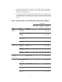
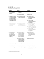
1
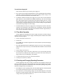
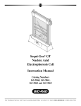
Model 200/2.0
Power Supply
Instruction
Manual
Catalog Numbers
165-4761 and 165-4762
For Technical Service Call Your Local Bio-Rad Office or in the U.S. Call 1-800-4BIORAD (1-800-424-6723)
Table of Contents
Page
Section 1
General Information....................................................................................1
1.1
1.2
1.3
1.4
1.5
General Information ...................................................................................................1
Safety ..........................................................................................................................1
Specifications .............................................................................................................2
Diagram of Front Panel..............................................................................................3
Description of Membrane Control Pad......................................................................3
Section 2
Operation ......................................................................................................4
2.1
2.2
2.3
Standard Mode Operation ..........................................................................................4
Time Mode Operation ................................................................................................5
Checking and Changing Operating Parameters.........................................................5
Section 3
Blotting Applications ...................................................................................6
3.1
Required Steps for Proper Blotting Results...............................................................6
Section 4
Troubleshooting Guide ................................................................................8
i
Note
To insure best performance from the Model 200/2.0 Power Supply, become fully acquainted with
these operating instructions before use.
Model
Catalog No.
Date of Delivery
Warranty Period
Serial No.
Invoice No.
Purchase Order No.
Warranty
Bio-Rad Laboratories warrants the Model 200/2.0 Power Supply against defects in materials and
workmanship for 1 year. If any defects occur in the instrument during this warranty period,
Bio-Rad Laboratories will repair or replace the defective parts free. The following defects, however,
are specifically excluded:
1. Defects caused by improper operation.
2. Repair or modification done by anyone other than Bio-Rad Laboratories or an authorized
agent.
3. Use of spare parts supplied by anyone other than Bio-Rad Laboratories.
4. Damage caused by accident or misuse.
5. Damage caused by disaster.
6. Corrosion due to use of improper solvent or sample.
For any inquiry or request for repair service, contact Bio-Rad Laboratories after confirming the
model and serial number of your instrument.
ii
Section 1
Introduction
1.1 General Information
Bio-Rad’s Model 200/2.0 microprocessor controlled power supply provides constant
voltage to dual output jacks under a variety of operating conditions. Voltage is continuously
adjustable from 5 to 200 volts, producing up to 200 watts of power. Current limits can be set
from 0.01 to 2.0 amperes to control the current generated. Although the power supply is
especially useful in blotting applications, it is also useful for nucleic acid electrophoresis and
for applications using the Mini-PROTEAN® II vertical electrophoresis cell.
Features of the Model 200/2.0 power supply include:
•
3-digit LED display to show operating and limit parameters
•
3-speed adjustment buttons to quickly adjust running parameters
•
Two operating modes: standard, to run electrophoresis manually; and time, to run
for a set time period
•
Constant current operation using the continuously adjustable current limit function
•
Automatic switching to constant current operation when the current exceeds the
current limit
•
Automatic no-load sensing
•
Continuous monitoring of load resistance, power output, and volt-hours during the
run
1.2 Safety
Caution: The Model 200/2.0 power supply is to be operated only by qualified personnel.
Read this entire instruction manual thoroughly before using the power supply.
1. For the internal cooling fan to function properly, the sides of the power supply require 6
cm or more of clearance. Do not block the fan.
2. Always connect the supply to a separate 3-prong, grounded AC outlet. Handle only one
lead wire at a time when connecting a load to the power supply.
3. Do not operate the Model 200/2.0 power supply in extreme humidity (≥ 95%), or where
condensation can short the electrical elements.
4. When operating the power supply in a coldroom, wrap it in a plastic bag and let it equilibrate
to temperature for 2 hours or more. After thermal equilibration, remove the supply
from the bag and begin operation. Follow the same procedure for re-equilibration to room
temperature.
Note: The Model 200/2.0 power supply will perform at temperatures between 0° and 35 °C.
It has also passed tests for operation with humidity between 0 and 95% under conditions
where condensation is absent. Operating the power supply outside of these conditions is not
recommended, and will void the warranty.
5. Do not store any item on top of the power supply.
1
1.3 Specifications
Output voltage
5-200 volts DC, continuously adjustable
Output current
0.01-2.0 A, continuously adjustable
Output terminals
Floating dual output jacks in parallel
Set limits
Current:
Power:
0.01-2.0 A, 0.01 A steps, fully adjustable
200 watts maximum output
Automatic crossover upon reaching limit.
Timer control
0.1-99.9 hours, 0.1 H steps, continuously adjustable
Set point resolution
Voltage:
Current limit:
Time set:
± 1 V, 5-200 VDC
± .01 A, .01-2.0 A
+ 0.1 H, 0.1-99.9 hours
Readout accuracy
Voltage:
Current limit:
Timer:
+1V
+ .05 A
2 seconds per hour
Overload and
short protection
Fuse
No load detection
LED display and alarm
Operating temperature
Operating humidity
0-35 °C
0-95%, in the absence of condensation
Line voltage (frequency)
100/120 V model
220/240 V model
90 - 132 VAC (47-63 Hz)
198 - 264 VAC (47-53 Hz)
Line regulation
± 3% or less
Load regulation
± 5% or less
RMS ripple and noise
Less than 5% at 100 VDC and 1 A. Less than 7% at any load
(not exceeding current limit)
Drift
± 1 volts
Dimensions (W x L x H)
16.5 x 31 x 13.5 cm
Weight
5.45 kg
2
1.4 Diagram of Front Panel Membrane Control Pad
1.5 Description of Membrane Control Pad
1. LED display
Displays the current limit, voltage, and timer parameters while
they are being set. Displays the operating parameters of current,
current limit, voltage, time, load resistance, power output, and
volt-hours during a run.
2. Mode indicator lights
When a function button is pressed, the indicator light above it
will illuminate, indicating that the LED is displaying that
parameter. When the power supply is operating at constant
current, the light above LIMIT will be flashing.
3. VOLTS
Press this button to set the voltage or to view the operating
voltage.
4. AMPS
Press this button to view the operating current. Press this button
and then either RAISE or LOWER to observe load resistance,
power output, and volt-hours during a run.
5. LIMIT
Press this button to set or view the current limit.
6. TIMER
Press this button to set or view the timer.
7. RAISE
Press this button to adjust the voltage, current limit, or timer
parameters upward.
8. LOWER
Press this button to adjust the voltage, current limit, or timer
parameters downward.
9. Output terminals
Connect the leads to the electrophoresis apparatus here.
3
Section 2
Operation
2.1 Standard Mode Operation
General Application: The standard mode is used in blotting applications and in nucleic
acid electrophoresis experiments where timing the run is not important. In this mode, the supply
is programmed to run at constant voltage within set current limits.
Set the Current Limit
1. Press LIMIT. The red indicator light above the button should be on. The LED should
read 2.00.
2. Press and hold LOWER. Release when the current limit shown in the LED reaches the
desired setting. If the desired limit is overrun, use RAISE to adjust the limit upward.
3. The current limit default is 2.0 amperes. If a current limit is not set, the power supply
will default to this limit for voltages set below 100 V. If the voltage is set above 100 V,
the power supply will automatically adjust the current limit based on its 200 watt output
capability. The adjusted current limit will be determined by the equation:
limit =
200 watts
volts
4. The current limit can be adjusted during the run by pressing LIMIT and adjusting the
parameter with either RAISE or LOWER.
Set the Voltage
1. Press VOLTS. The red indicator light above the button should be on. The LED should read
OFF.
2. Press and hold RAISE until the LED displays the desired voltage setting. The power supply
starts running as soon as a voltage reading is shown on the LED display. If the desired
setting is overrun, use LOWER to adjust the setting downward.
3. If a voltage is set that generates a current exceeding the current limit set, the power supply
will automatically switch to operating at constant current when it reaches the current
limit. The red indicator light above LIMIT will flash. The voltage displayed on the LED
will be the actual voltage, rather than the set voltage. The display reverts to actual voltage
5 seconds after the voltage has been set. When a current limit above 1.0 amperes is set,
the power supply will automatically adjust the current limit downward if a voltage that
would exceed the 200 watt output limit of the power supply is set. If the set voltage is
reduced, the power supply will automatically return to the original current limit that was
set.
4. The voltage can be adjusted during a run by following steps 1 and 2 above.
4
Turn the Power Supply Off
There are three different ways to turn the power supply off.
1. Press VOLTS. The red indicator light should be on. Press LOWER until the LED display
reads OFF. Using this method preserves the volt-hour reading until the voltage is reset,
but resets all of the other functions to their default values.
2. An alternative method to turn the power supply off is to press VOLTS. The red indicator
light should be on. Press RAISE and LOWER simultaneously. The LED will display
OFF. If the load has already been disconnected, the LED will display OFF for 1 second,
then the decreasing voltage will be shown until it reaches 30 volts. Below 30 volts, OFF
will be displayed. Using this method preserves the volt-hour reading as long as RAISE is
not held down long enough to reset the voltage.
3. The third method to turn the power supply off is to turn the power switch off. This automatically resets all functions to their default values, including the volt-hour integration
data. Note: The power supply left on with no load attached consumes approximately 12
watts of power (equivalent to a night light).
2.2 Time Mode Operation
General Application: The Model 200/2.0 power supply can operate at constant voltage or
constant current for a set time. The power supply automatically shuts off and the alarm sounds
when the set time has elapsed.
1. Set the current limit as in Section 2.1.
2. Set the timer.
•
Press TIMER. The red indicator light above the button should be on, and the LED display
should read 00.0.
•
Press and hold RAISE until the LED display reads the correct time. The timer displays
tenths of hours. It may be necessary to use both RAISE and LOWER to reach the desired
setting.
3. Set the voltage as in Section 2.1.
4. The timer begins to count as soon as the voltage is above zero, and will count down from
the set time to zero. When the timer reaches zero, the alarm will sound, and the power
supply will shut off. The LED display will read OFF.
5. To turn the alarm off, press any one of the function buttons.
6. Turn the power switch off, if desired.
2.3 Checking and Changing Operating Parameters
General Application: The current, voltage, current limit, time remaining (if the timer has
been set), resistance load, power output, and volt-hours can be checked during a run to monitor
the progress of the experiment or to troubleshout. The current limit, operating voltage, and set
time may be changed at any time during a run.
1. Press AMPS to view the operating current. The red indicator light above the button should
be on, and the operating current will be shown on the LED display.
2. Press VOLTS to view the operating voltage. The red indicator light above the button
should be on, and the operating voltage will be registered on the LED display. To alter the
voltage, follow the procedure in Section 2.1.
5
3. Press LIMIT to view the set current limit. The red indicator light above the button should
be on, and the set limit will be shown on the LED display. To adjust the current limit,
follow the procedure in Section 2.1.
4. Press TIMER to view the remaining time on the timer. The red indicator light above the
button should be on, and the time remaining will be shown on the LED display. To change
the time remaining for the run, follow the steps detailed in Section 2.2, item 2.
5. To view the resistance laod, power load, and volt-hours settings, press AMPS, and then
press either RAISE or LOWER. The indicator light above AMPS will go off, and the
LED display will alternately flash rLD and the resistance value in thousands of ohms.
Press RAISE or LOWER again, and the LED display will alternately flash PLD and the
power output in watts. Press RAISE or LOWER again, and the LED display will alternately
flash E-H and the volt-hour reading in thousands of volt-hours.
Section 3
Blotting Applications
3.1 Required Steps for Proper Blotting Results
Observe the following guidelines to avoid mishaps that may result in serious damage to
the instrument or injury to the operator:
1. Read the Trans-Blot® cell instruction manual before beginning electrophoretic transfers.
2. Do not attempt high intensity transfers or overnight runs until you are completely familiar
with your system.
3. Pre-equilibrate electrophoresis gels in transfer buffer before beginning transfer to remove
contaminating electrophoresis buffer salts or neutralization salts that will increase the
conductivity of the transfer buffer. The length of time required for pre-equilibration
depends on the gel thickness, and can range from 20 minutes for 0.75 mm thick SDS
polyacrylamide gels to 1 hour for 3-6 mm thick DNA agarose gels. The gel can be
pre-equilibrated in a shorter time if the pre-equilibration buffer is changed several times.
4. Use the General Guide to Transfer Buffers and Running Conditions (Table 1) as a guideline in setting current limits on the power supply. Unless proper current limits have been
set, uncontrolled conductivity changes may result in full power being delivered to the
Trans-Blot cell. This is a safety hazard due to the excessive heat (power). In this situation,
the transfer buffer may boil and evaporate, causing the gel holder and electrode cards to
deform.
5. Operating the Trans-Blot cell in the coldroom is an inadequate means of controlling transfer
buffer temperature. For high power applications, efficient heat removal is obtained only
by using the Super Cooling Coil connected to a refrigerated recirculating bath capable
of 200-300 watt heat extraction at ambient evaporation temperature.
6. Place a stirring bar inside the Trans-Blot cell and stir during transfer to help maintain uniform
buffer conductivity and temperature.
7. Buffer preparation is extremely important. Do not pH adjust transfer buffers unless specifically
indicated in the instruction manual. Use only high quality, reagent grade methanol. Do not
reuse transfer buffers.
6
8. Sponge pads can not dissipate heat as effectively as Scoth Brite® gel pads. For high power,
high intensity applications, it is advisable to use gel pads in place of sponge pads to
minimize localized heating effects.
9. Do not increase voltage settings beyond those indicated in Table 1 for overnight operation.
If overnight transfers at low voltages are ineffective for your application and you must
increase the voltage, you must also decrease the transfer time and/or provide external
cooling.
Table 1. General Guide to Transfer Buffers and Running Conditions
POWER RANGES
TRANSFER
O-Farrell two-dimensional
SDS-Protein
(Laemmli, etc.)
Low Field, Uncooled
Lengthy or Overnight
Standard Field
Cooling Optional
Runs 5 Hours
High Intensity Field
CoolingRequired to
0-4 °C, Runs 30
Minutes to 4 Hours
BUFFER
25 mM Tris, pH 8.3
192 mM glycine,
20% (v/v) methanol
BLOT MEDIA
Nitrocellulose, DEAE
30 V
0.1 A
60 V
0.21 A
100 V
150 V
200 V
0.36 A
0.55 A
0.82 A
25 mM Tris, pH 8.3
192 mM glycine,
(no methanol)
Zeta-Probe® membrane
30 V
0.1 A
60 V
0.21 A
100 V
150 V
200 V
0.36 A
0.55 A
0.82 A
25 mM sodium
phosphate, pH 6.5 or
DBM, DPT
15 V
0.32 A
40 V
1.01 A
70 V
1.86 A
10 mM sodium
borate, pH 9.2
DBM, DPT
15 V
0.19 A
50 V
0.72 A
70 V
90 V
1.03 A
1.45 A
25 mM Tris, pH 8.3
192 mM glycine,
(no methanol)
Nitrocellulose,
Zeta-Probe membrane,
DEAE
30 V
0.1 A
60 V
0.21 A
100 V
150 V
200 V
0.36 A
0.55 A
0.82 A
25 mM sodium
phosphate, pH 6.5 or
DBM, DPT
15 V
0.32 A
40 V
1.01 A
70 V
1.03 A
10 mM sodium
borate, pH 9.2
DBM, DPT
15 V
0.19 A
50 V
0.72 A
70 V
90 V
1.03 A
1.45 A
Isoelectric focusing
Native gels - basic
proteins, acid urea gels
0.7 % acetic acid
Nitrocellulose,
Zeta-Probe membrane,
DEAE
30 V
0.16 A
70 V
0.49 A
100 V
150 V
0.55 A
0.85 A
DNA, RNA
10 mM Tris, pH 7.8
5 mM sodium acetate
0.5 mM EDTA
Zeta-Probe membrane,
DEAE
30 V
0.28 A
60 V
0.60 A
80 V
100 V
0.83 A
1.03 A
50 mM Tris, pH 8.3
50 mM boric acid
1.0 mM EDTA
Zeta-Probe membrane
20 V
0.12 A
80 V
0.45 A
25 mM sodium
phosphate, pH 5.5
DBM, DPT
15 V
0.22 A
40 V
0.68 A
60 V
85 V
1.09 A
1.57 A
10 mM sodium
acetate, pH 4.0
DBM, DPT
20 V
0.15 A
70 V
0.54 A
100 V
125 V
0.8 A
1.03 A
Native gels
Acidic or neutral proteins
7
Section 4
Troubleshooting Guide
Condition
1. With the power supply
on, the LED fails to
illuminate.
Cause
1a. Power cord is not properly
connected.
Remedy
1a. Check connections.
1b. The fuse has blown.
1b. Replace fuse.
2. With the power supply
on, and the current limit
and voltage set, there
is not current registered
when AMPS is pressed.
2a. The electrophoresis cell
(load) is not connected
2a. Check the electrophoresis cell for circuit
interruption.
3. During run, the LED
flashes nLD and the
alarm sounds.
3a. The supply has detected
a sudden interruption of
the circuit and turned off.
3a. Turn power supply off.
Disconnect load and
check for broken wires.
3b. Check the electrophoresis
cell for circuit interruption.
3c. Check to see that
electrophoresis cell leads
are plugged in.
4. Desired voltage is
not displayed on
the LED. Indicator
light above LIMIT
is flashing.
4a. The power supply is
operating at constant
current. The voltage
was set too high for
the set current limit.
4a. Reset the voltage, if
desired. Can reset the
current limit, if 4b does
not apply.
4b. The power supply is
operating at constant
current. Conductivity
of buffer is too high.
4b. Remake the buffer.
5. Fuse blows frequently.
5a. Abnormality inside unit.
5a. Contact Bio-Rad or
technical representative.
6. LED displays OFF,
alarm is sounding.
6a. Timer has counted down
and shut off power supply.
6a. Press one of the buttons
to turn off alarm. Reset
current limit, voltage, and
timer, if desired.
2b. Check to see that
electrophoresis cell leads
are plugged in.
Scotch Brite is a registered trademark of 3M Company.
8
Bio-Rad
Laboratories
Life Science
Group
2000 Alfred Nobel Drive
Hercules, California 94547
Telephone (510) 741-1000
Fax: (510) 741-1060
Eastern Regional Office, 85A Marcus Dr., Melville, New York 11747 • Phone (516) 756-2575 • Fax (516) 756-2594
Australia, Bio-Rad Laboratories Pty Limited, Unit 11, 112-118 Talavera Rd P.O. Box 371, North Ryde, NSW 2113 • Phone 02-805-5000 • Fax 02-805-1920
Austria, Bio-Rad Laboratories Ges.m.b.H., Auhofstrasse 78D, 1130 Wien • Phone (1) 877 89 01 • Fax (1) 876 56 29
Belgium, Bio-Rad Laboratories S.A./N.V., Begoniastraat 5, 9810 Nazareth Eke • Phone 09-385 55 11 • Fax 09-385 65 54
Canada, Bio-Rad Laboratories (Canada) Ltd., 5671 McAdam Road, Mississauga, Ontario L4Z 1N9 • Phone (905) 712-2771 • Fax (905) 712-2990
China, Bio-Rad Laboratories, 14, Zhi Chun Road, Hai Dian District, Beijing 100088 • Phone (01) 2051873 • Fax (01) 2051876
France, Bio-Rad S.A., 94/96 rue Victor Hugo, B.P. 220, 94 203 Ivry Sur Seine Cedex • Phone (1) 49 60 68 34 • Fax (1) 46 71 24 67
Germany, Bio-Rad Laboratories GmbH, Heidemannstraße 164, D-80939 München/Postfach 450133, D-80901 München • Phone 089 31884-0 • Fax 089 31884-100
Italy, Bio-Rad Laboratories S.r.l.,Via Cellini, 18/A, 20090 Segrate Milano • Phone 02-21609.1 • Fax 02-21609-399
Japan, Nippon Bio-Rad Laboratories, Sumitomo Seimei Kachidoki Bldg, 3-6 Kachidoki, 5-Chome, Chuo-Ku, Tokyo 104 • Phone 03-3534-7665 • Fax 03-3534-8497
The Netherlands, Bio-Rad Laboratories B. V., Fokkerstraat 10, 3905 KV Veenendaal • Phone 08385-40666 • Fax 08385-42216
New Zealand, Bio-Rad Laboratories Pty Ltd., P. O. Box 100-051, North Shore Mail Centre, Auckland 10 • Phone 09-443 3099 • Fax 09-443 3097
Pacific, Bio-Rad Laboratories, Unit 1111, 11/F., New Kowloon Plaza, 38, Tai Kok Tsui Road, Tai Kok Tsui, Kowloon, Hong Kong • Phone 7893300 • Fax 7891257
Singapore, Bio-Rad Laboratories (Singapore) Ltd., 464 Siglap Road, #01-02 Flamingo Valley, Singapore 1545 • Phone (65) 4432529 • Fax (65) 4421667
Spain, Bio-Rad Laboratories, S. A. Avda Valdelaparra 3, Pol. Ind. Alcobendas, E-28100 Alcobendas, Madrid • Phone (91) 661 70 85 • Fax (91) 661 96 98
Sweden, Bio-Rad Laboratories AB, Gärdsvägen 7D, Box 1276, S-171 24 Solna • Phone 46-(0)8-735 83 00 • Fax 46-(0)8-735 54 60
Switzerland, Bio-Rad Laboratories AG, Kanalstrasse 17, 8152 Glattbrugg • Phone 01-810 16 77 • Fax 01-810 19 33
United Kingdom, Bio-Rad Laboratories Ltd., Bio-Rad House, Maylands Avenue, Hemel Hempstead, Herts HP2 7TD • Free Phone 0800 181134 • Fax 01442 259118
SIG 071494
Printed in USA
M1654761 Rev B