1
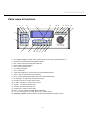
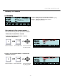
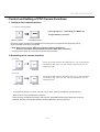
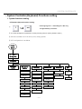
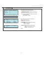
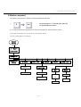
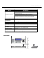
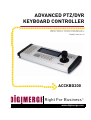
ADVANCED PTZ/DVR
KEYBOARD CONTROLLER
INSTRUCTION MANUAL
English Version 1.0
ACCKBD200
Right For Business™
www.digimerge.com
Copyright ¤ 2009 Digimerge Technology Inc.
SYSTEM CONTROLLER
WARNING
TO REDUCE THE RISK OF FIRE OR ELECTRIC SHOCK, DO NOT EXPOSE THIS PRODUCT TO RAIN
OR MOISTURE. DO NOT INSERT ANY METALLIC OBJECTS THROUGH THE VENTILATION GRILLS OR
OTHER OPENINGS ON THE EQUIPMENT.
The lightning flash with arrowhead symbol, within
an equilateral triangle, is intended
To alert the user to the presence of uninsulated "dangerous voltage" within the
product's enclosure that may be of sufficient
magnitude to constitute a risk of electric
shock to persons.
The exclamation point within an equilateral triangle
is intended to alert the user to
The presence of important operating and
maintenance (servicing) instruction in
the literature accompanying the product
FCC COMPLIANCE STATEMENT
FCC INFORMATION: THIS EQUIPMENT HAS BEEN TESTED AND FOUND TO COMPLY WITH THE LIMITS FOR A
CLASS A DIGITAL DEVICE, PURSUANT TO PART 15 OF THE FCC RULES. THESE LIMITS ARE DESIGNED TO
PROVIDE REASONABLE PROTECTION AGAINST HARMFUL INTERFERENCE WHEN THE EQUIPMENT IS
OPERATED IN A COMMERCIAL ENVIRONMENT. THIS EQUIPMENT GENERATES, USES, AND CAN RADIATE
RADIO FREQUENCY ENERGY AND IF NOT INSTALLED AND USED IN ACCORDANCE WITH THE INSTRUCTION
MANUAL, MAY CAUSE HARMFUL INTERFERENCE TO RADIO COMMUNICATIONS. OPERATION OF THIS
EQUIPMENT IN A RESIDENTIAL AREA IS LIKELY TO CAUSE HARMFUL INTERFERENCE IN WHICH CASE THE
USER WILL BE REQUIRED TO CORRECT THE INTERFERENCE AT HIS OWN EXPENSE.
CAUTION: CHANGES OR MODIFICATIONS NOT EXPRESSLY APPROVED BY THE PARTY RESPONSIBLE FOR
COMPLIANCE COULD VOID THE USER'S AUTHORITY TO OPERATE THE EQUIPMENT.
CE COMPLIANCE STATEMENT
WARNING
THIS IS A CLASS A PRODUCT. IN A DOMESTIC ENVIRONMENT THIS PRODUCT MAY CAUSE RADIO
INTERFERENCE IN WHICH CASE THE USER MAY BE REQUIRED TO TAKE ADEQUATE MEASURES.
-2-
SYSTEM CONTROLLER
CONTENTS
General Descriptions, Features
Installation
…….. ………………………..…. 4
……………….....………………….…..…….5
Part names & Functions …………………... ………….…….………….6
Display LCD window ……………………....………………….......…….9
PTZ Control
…..….……………....…...……....….…..…10
PTZ Configuration
…..….……………....…...……....….…..…10
Hidden command …………………………………....………….………13
Specifications & Dimensions .………………....…………………………14
-3-
SYSTEM CONTROLLER
General Descriptions
The ACCKBD-200 is a pan/tilt controller and it allows operators to perform the
following functions :
• Controls camera functions such as pan, tilt, zoom, and focus.
• Sets and calls camera preset positions
• Activates pre-programmed group presets, tour and group sequences.
The LCD is used to display current status as well as to provide a menu system for setting
operational parameters.
Controller is designed for desktop operation; interface connectors are located in the Junctions box
outer of the unit.
Features
• Recalls up to 255 cameras from one keyboard.
• Multiple protocol supported in each channel (Pelco D/P, Dongyang DRX-502, Samsung Techwin
SPD-2500, Samsung Electronics SCC-643)
• Preset position control.
• Variable manual control speed from 1°/sec to 90°/sec
• Maximum speeds are proportional to zoom ratio.
• Recalls programmed guard tours from each dome camera.
• Recalls Auto-Swing from selected dome camera.
• Built-in Graphic LCD monitor with blue screen.
• Programmable user preferences. (preset, tour, pattern, group, etc.)
• User password support.
• Easy upload programmed data via serial communication port of computer.
• Slave Keyboard support.
-4-
SYSTEM CONTROLLER
Installation
UNPACKING
Unpack the equipment and make sure all listed items are included in the box.
Product Carton 1
Keyboard controller ………………………………………………….……… 1
Junction box ………………………………………………………….………. 2
3m 6p cable RJ-11………………………………………………….………… 2
Instruction manual ….………….…………………………………………….. 1
Product Carton 2
12V DC Power Adaptor .……………………………………………………………. 1
1. CONNECTIONS
There are two connectors on the controller. These connectors are RJ connector for Master and
Slave control.
1.1 Open the junction box cover and connect the 12VDC power to the junction box number 3 and 6.
1.2 Connect 6-pin multi-wired cable between junction-box and keyboard.
1.3 Connect PTZ communication wires (RS-485, 2-wires) to the junction box number of 1 and 2.
1.4 Turn on the power , then you will get into the starting mode.
Junction Box
RJ-11 Cable
④
⑤
⑥
①
②
③
⑦
< Configuration of Junction Box >
① RS-485 (+) :Connect to PTZ (+)
② RS-485 (-) : Connect to PTZ(-)
③ Power input : DC12V (-)
④ Not used
⑤ Not used
⑥ Power input : DC12V (+)
⑦ RJ-11 Modular Jack : Connect to Controller
-5-
Slave Port
Master Port
SYSTEM CONTROLLER
Parts name & functions
3
4
5
2
1
19
20 21
15 16 17
18
22
6
7
8
9
10 11 12
13 14
1. LCD Display: Displays numeric input, system status, function status, general status, etc.
2. Shows the communication status (Master / Slave)
3. Mon : Select output channel of Matrix Switcher
4. Quad : Select channel of Quad
5. Mux : Select channel of Mux
6. 0~9 :Numeric keypad :
7. CLR : Cancel key .
8. CAM :Select address of Camera, Mux, Quad and Matrix Switcher.
9. SHIFT : Key for special function (Customize).
10. SET : Connected equipment setting and system information setting.
11.12. IRIS Open ,12. IRIS Close :Camera Iris control.
13. 20.Near / Far Focus: Camera focus control.
14.21. Wide / Tele Zoom : Camera zoom control.
15. AUX On : AUX ON of Receiver unit.
16. AUX Off : AUX Off of Receiver unit.
17. System Hold : Used for system hold
18. Menu : Used for Camera (Pan/Tilt) Menu adjustment.
19. F1 ~ F5 : Function Keys (Preset, Group, Tour, Pattern, Scan).
22. Telemetry Joystick – It allows precise control of Pan/Tilt/Zoom & Moving to menu
-6-
SYSTEM CONTROLLER
Parts name & functions
1
2
1. Slave Port : Connect to Slave Communication Port.
2. Master Port : Connect to Master Communication Port
Drawing of Console Desk
The ACCKBD200 is designed to use on the console desk.
When you install the keyboard on the console desk , please make holes as below drawing.
Unit : mm
-8-
SYSTEM CONTROLLER
Display LCD window
(1) Initial display
PROTOCOL
PELCO-D : 2400 BPS
PTZ ADDR
001
MON CHAN
001
PRE
GRO
TOUR
SCAN
PATT
FOCUS
1. C-001 : Shows the current camera No. (Address).
2. M-001 : Displays output channel of Matrix Switcher. (TBD)
3. DRX5 : Shows the selected camera protocol.
4. Func : Displays entered Key.
ZOOM
< Fig 1.1 >
Accessing to the camera menu :
This function is only for the speed dome camera
Select and control the camera
1) How to select Address Number 1 camera
with Pelco-D protocol?
1
Camera Address
CAM
Press CAM button
Move to next item
PROTOCOL
PELCO-D : 2400 BPS
PTZ ADDR
001
MON CHAN
001
PRE
GRO
TOUR
SCAN
PATT
FOCUS
ZOOM
by using joystick
2) How to select Address Number 2 camera with
DRX-502 protocol?
2
Camera Address
CAM
Press CAM button
Move to next item
by using joystick
-9-
PROTOCOL
DRX502A : 9600 BPS
PTZ ADDR
002
MON CHAN
001
PRE
GRO
TOUR
SWING
AUTO
FOCUS
ZOOM
SYSTEM CONTROLLER
• Control and Setting of PTZ Camera Functions
1. Setting to the camera functions
① Camera Setting Menu
1
Camera Address
<Pressing keypad “1” and holding the “MENU” key
MENU
for approximately 2 seconds>
Press MENU button
Each menu page is provided with a highlighted cursor which can be moved around the page using the Up,
Down Left & Right cursor keys with Joystick.
** Note: Dome camera menu is different according to camera manufacturers.
Please be noted dome camera instruction manual in detail menu explanation.
** In Pelco protocol, press “95” and “preset” to get into the Dome menu
2.Accessing to the camera functions
① Preset
1
Preset number
F1
Press the preset number and PRE key(F1) on the keyboard.
The Monitor will show you the function name and you are
operating now.
PRE KEY
① Group
1
Group number
F2
Press the preset number and GRO key(F2) on the keyboard.
The Monitor will show you the function name and you are
operating now.
GRO KEY
※ To using Preset, Group, Tour, Scan, Auto pan, Focus, Zoom functions of keyboard, user should store
these functions on the camera Menu in advance.
These functions are different according to manufacturer. ACCKBD200 series support Pelco D/P, Dongyang
DRX-502, Samsung Techwin SPD-2500 and Samsung Electronics SCC-643 protocols.
- 10 -
SYSTEM CONTROLLER
• System Controller (Keyboard) Functions setting
1. System functions setting
PTZ Camera (Rx) and Protocol setting.
①
<Pressing keypad “1” and holding the “SET” key
1
SET
for approximately 2 seconds>
② You will be prompted for a password if one has previously been set (factory default is “0000”.)
③ Set the information as LCD show you by using joystick.
④ PTZ Configuration is as below.
System
Setting
‘1’ + SET(-)
(2 seconds)
PASSWORD
Equipment
number
Equipment
number
PROTOCOL
COMM SPEED
JOYSTICK
EXIT
PTZ
PELCO-D
2400BPS
PROP.
Save &
Exit
PTZ-K1
PELCO-P
4800BPS
CAMERA
DRX-502
9600BPS
DVR
PELCO-A
19200BPS
MATRIX
SPD-2500
38400BPS
QUAD
SCC-643
ON-OFF
Exit only
ETC.
- 11 -
SYSTEM CONTROLLER
ACCKBD2000
PROTOCOL
PELCO-D : 2400 BPS
PTZ ADDR
001
MON CHAN
001
Accessing the system setup menu
Pressing keypad 1 and then holding the SET key for
approximately 2 seconds.
It provides access to the system setup menu system.
PRE GRO TOUR SCAN PATT FOCUS ZOOM
Note: You will be prompted for a password if one has
previously been set
(factory default is “0000”)
PASSWORD?
NO. : Select camera address to be changed.
1.
NO.
001
2.
TYPE
PTZ
TYPE : Select camera type.
3.
PROTOCOL
DRX-502
PROTOCOL : Protocol select.
4.
COMM SPEED
2400 BPS
COMM SPEED : Select communication speed
** DRX-502 : 9600 bps
** Pelco D : 2400 bps
5.
JOYSTICK
6.
EXIT
JOYSITCK: Select the way of Joystick control.
PROP
PROP : Proportional speed control.
ON-OFF : Fixed speed control.
EXIT
- 12 -
SYSTEM CONTROLLER
2.Hidden command
This hidden menu performs to operator to change PASSWORD and others.
①
2
SET
<Pressing keypad “2” and holding the “SET” key
for approximately 2 seconds>
② You will be prompted for a password if one has previously been set (factory default is “0000”.)
③ Set the information as LCD show you by using joystick.
④ PTZ Configuration is as below.
System
setting
‘2’ + Set(-)
(2 seconds)
PASSWORD
PASSWORD
Setting
OP Mode
Master
Slave
Sleep Time
Joystick
Version
OEM Logo
Exit
Buzzer
Save &
ON
Factory set
Start
Cancel
Exit
OFF
Exit Only
- 13 -
SYSTEM CONTROLLER
Specifications
Model
ACCKBD200
Pan/Tilt interface: RS-485
DVR interface: RS-485
Keyboard Communication
Pan/Tilt operating distance: 4000 ft (1029m) on 24AWG wire
Protocol: Multiple (Pelco D/P, Dongyang DRX-502, Samsung Techwin
SPD-2500, Samsung Electronics SCC-643), Baud rate selectable
Connector Type Data
RJ-11 6-pin modular
PC Keyboard button
Keyboard Keypad
Numeric keypad and camera function keys.
Joystick
Three-axis, vector solving, with twisting, return-to-center head
Input Voltage
12V DC±2V
Power Consumption
Max.150mA
LCD Display
Graphic display 240 x 64dots. Display 4-linex30-character
alphanumeric LCD display with blue backlight.
Operating Temperature
0℃ to 45℃
Humidity
10% -70% non-condensing
Dimensions & Weight
376(W) x 112(H) x 145(D), 1.3Kg
Dimensions
W
D
H
- 14 -