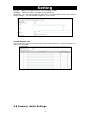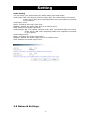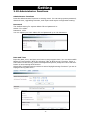
1
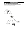
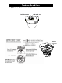
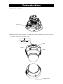
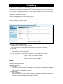
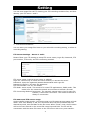
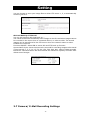
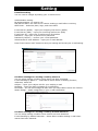
NETWORK CAMERA Instruction Manual 830 A.8_CD Introduction Table of Contents Introduction 1.1 Introductions…………........................................................................ 1 1.2 Important Safeguards…………….......................................................... 2 1.3 Notes on Use and Installation............................................................ 5 1.4 Accessories………………………………………………………………………………………………… 6 1.5 Precautions for Use…………................................................................ 7 1.6 AC Adapter.................................................................................... 8 1.7 Overview of the Network Camera...................................................... 9 1.8 Features of the Camera................................................................... 10 1.9 Names of Camera Parts................................................................... 11 1.10 Installing the Camera.................................................................... 12 1.11 Setting Network Camera Environment.............................................. 15 1.12 Connecting the Camera and Personal Computer by Network................. 16 1.13 Using the Camera Search Application "Camera Finder"........................ 18 1.14 Log-in Screen………........................................................................ 19 1.15 Viewing and Listening.................................................................... 20 Set up 2.1 Setting......................................................................................... 22 2.2 Camera/Basic Settings.................................................................... 23 2.3 Camera/Compression Settings......................................................... 26 2.4 Camera/Event Settings................................................................... 27 2.5 Camera/SD Recording..................................................................... 29 2.6 Camera/FTP Recording Settings........................................................ 31 2.7 Camera/E-Mail Recording Settings.................................................... 33 2.8 Camera/Audio Settings.................................................................... 35 2.9 Network Settings............................................................................ 36 2.10 Administrator Functions................................................................. 38 2.11 Event Log.................................................................................... 40 2.12 Information................................................................................. 41 2 Introduction 1.1 Introduction Thank you for purchasing this Network Camera. Before you start using the camera, read this manual carefully to ensure correct usage. Once you have finished reading this manual, keep it in a convenient place for future reference. The design, specifications, software, and manual contents are subject to change without prior notice. This camera is for indoor use only. Do not install it outdoor without applicable outdoor housing and accessories. This device complies with part 15 of the FCC Rules. Operation is subject to the following two conditions: (1) This device may not cause harmful interference, and (2) This device must accept any interference received, including interference that may cause undesired operation. This equipment has been tested and found to comply with the limits for a Class B digital device, pursuant to part 15 of the FCC Rules. These limits are designed to provide reasonable protection against harmful interference in a residential installation. This equipment generates, uses and can radiate radio frequency energy and, if not installed and used in accordance with the instructions, may cause harmful interference to radio communications. However, there is no guarantee that interference will not occur in a particular installation. If this equipment does cause harmful interference to radio or television reception, which can be determined by turning the equipment off and on, the user is encouraged to try to correct the interference by one or more of the following measures: - Reorient or relocate the receiving antenna. - Increase the separation between the equipment and receiver. - Connect the equipment into an outlet on a circuit different from that to which the receiver is connected. - Consult the dealer or an experienced radio/TV technician for help. Terms and Trademarks ● The term "OS" is used in this manual to indicate operating systems compatible with this product. − Windows 2000: Microsoft® Windows® 2000 operating system − Windows XP: Microsoft® Windows® XP operating system ● The formal name of Windows® is Microsoft® Windows® Operating System. ● Microsoft® and Windows® are trademarks or registered trademarks of Microsoft ® Corporation in the United States and other countries. ● Other product names appearing in this manual may be trademarks or registered trademarks of their respective holders. 1 Introduction 1.2 Important Safeguards 1. Read Instructions All the safety and operating instructions should be read before the product is operated. 2. Retain Instructions The safety instructions and instruction manual should be retained for future reference. 3. Heed Warnings All warnings on the product and in the instruction manual should be adhered to. 4. Follow Instructions All operating and use instructions should be followed. 5. Cleaning Disconnect this camera from the power supply before cleaning. 6. Attachments Do not use attachments not recommended by the camera manufacturer as they may cause hazards. 7. Water and Moisture Do not use this camera near water, for example, near a bath tub, wash bowl, kitchen sink, or laundry tub, in a wet basement, or near a swimming pool and the like. 8. Accessories Do not place this camera on an unstable cart, stand, tripod, bracket or table. The camera may fall, causing serious injury to a child or adult and serious damage to the product. Use only with stand, tripod, bracket, or table recommended by the manufacturer, or sold with the camera. Any mounting of the product should follow the manufacturer's instructions, and should use a mounting accessory recommended by the manufacturer. 9. Ventilation This camera should never be placed near or over a radiator or heat register. This camera should not be placed in a built-in installation such as a bookcase or rack unless proper ventilation is provided or the manufacturer's instructions have been adhered to. 10. Power Sources This camera should be operated only from the type of power source indicated on the marking label. If you are not sure of the type of power supply to your location, consult your product dealer. 11. Power-Cord Protection Power-Supply cords should be routed so that they are not likely to be walked on 2 Introduction or pinched by items placed upon or against them, paying particular attention to cords at plugs, screws and the point where they exit from the product. 12. Installation This camera should be installed on a firm and solid part of the ceiling or wall. If installed on a soft and weak place, the camera unit may fall. A person under it may be injured and things under it may be damaged. 13. Lightning For added protection for this camera during a lightning storm, or when it is left unattended and unused for long periods of time, unplug it from the outlet and disconnect the power supply and cable system. This will prevent damage to the camera due to lightning and power-line surges. If lightning occurs, do not touch the unit or any connected cables in order to avoid electric shock. 14. Overloading Do not overload power supply and extension cords as this can result in a risk of fire or electric shock. 15. Object and Liquid Entry Never push objects of any kind into this camera through openings as they may touch dangerous voltage points or short-out parts that could result in a fire or electrical shock. Never spill liquid of any kind on the camera. 16. Servicing Do not attempt to service this camera yourself as opening or removing covers may expose you to dangerous voltage or other hazards. Refer all servicing to qualified service personnel. 17. Damage Requiring Service Disconnect this camera from the power supply and refer servicing to qualified service personnel under the following conditions. a. When the power-supply cord or plug is damaged. b. If liquid has been spilled, or objects have fallen into the camera. c. If the camera has been exposed to rain or water. d. If the camera does not operate normally by following the operating instructions in the instruction manual. Adjust only those controls that are covered by the instruction manual as an improper adjustment of other controls may result in damage and will often require extensive work by a qualified technician to restore the camera to its normal operation. e. If the camera has been dropped or the cabinet has been damaged. f. When the camera exhibits a distinct change in performance-this indicates a need for service. 18. Replacement Parts 3 Introduction When replacement parts are required, be sure the service technician has used replacement parts specified by the manufacturer with the same characteristics as the original part. Unauthorized substitutions may result in fire, electric shock or other hazards. 19. Safety Check Upon completion of any service or repairs to this camera, ask the service technician to perform safety checks to determine that the camera is in proper operating condition. The CAUTION label, shown on the above part, is attached on the camera. The lightning flash with arrowhead symbol, within an equilateral triangle, is intended to alert the user to the presence of uninsulated "dangerous voltage" within the product's enclosure that may be of sufficient magnitude to constitute a risk of electric shock to persons. The exclamation point within an equilateral triangle is intended to alert the user to the presence of important operating and maintenance (servicing) instructions in the literature accompanying the appliance. WARNING: TO REDUCE THE RISK OF FIRE OR ELECTRIC SHOCK, DO NOT EXPOSE THIS APPLIANCE TO RAIN OR MOISTURE. FIELD INSTALLATION: "THIS INSTALLATION SHOULD BE MADE BY A QUALIFIED SERVICE PERSON AND SHOULD CONFORM TO ALL LOCAL CODES." 4 Introduction 1.3 Notes on Use and Installation ・ Do not aim the camera at the sun Do not aim the camera at the sun or point it at sun even if you are not shooting. ・ Do not shoot intense light Intense light such as a spotlight may cause a bloom or smear. A vertical stripe may appear on the screen. However, this is not a malfunction. ・ Treat the camera with care Do not drop the camera or subject it to strong shock or vibration. Otherwise, the camera may malfunction. ・ Never touch internal parts Do not touch the internal parts of the camera other than the parts specified. Otherwise, the camera may malfunction. ・ Install the camera where no video noise appears If cables are wired near electric lighting wires or a TV set, noise may appear in images. In this event, relocate cables or reinstall equipment. ・ Check the ambient temperature and humidity Avoid using the camera where the temperature is hotter or colder than specified. Otherwise, the quality of images may deteriorate or internal parts may be affected. Special care is required to use the camera at high temperature and humidity. *Should you notice any trouble If any trouble occurs while you are using the camera, turn off the power and contact your dealer. Continued use in this state might cause fire or electric shock. For details on repair, consult the place of purchase, or please contact the technical support number. 5 Introduction 1.4 Accessories Confirm that all of the following accessories have been supplied with the network camera. CD-ROM (x1) The instruction manual and Camera Finder are contained. Quick Guide (x1) 2GB SD card (x1) Screw set: Wood screws (x4), Anchor (x4) 6 Introduction 1.5 Precautions for Use SD Memory Card ● There is a limit to the number of rewrites that is possible with the SD memory card. Replacing the SD memory card when performing periodic maintenance of the camera is recommended. ● The camera supports the following SD memory cards. Do not use memory cards with other specifications. SD memory card: 64, 128, 256, and 512 MB, 1 and 2 GB SD memory cards (3.3 V) supported. Physical interface: Part 1. Physical Layer Specification; Version 1.01 ● Images may not be recorded or read correctly if an unsupported SD memory card is used with the camera. ● Carefully read the manual, precautions on use, and any other information supplied with a purchased memory card. ● An SD memory card can be used for the loop recording of images. The life-span (number of rewrites possible) of an SD memory card is greatly affected by the capacity of the SD memory card. The use of a 128, 256, or 512 MB, 1 or 2 GB large-capacity SD memory card is recommended for loop recording. ● Do not use a memory card containing the data recorded by another device with the camera as this may result in the camera not functioning correctly. ● Do not modify, overwrite the data, or change the folder name of an SD memory card. It may result in the camera not to function correctly. ● Data recorded with the camera do not comply with the image file format Exit and the DCF standard. If the SD memory card is to be removed to play images, use a personal computer to play the images. Other devices may not be capable of displaying the images. 7 Introduction 1.6 Power Adapter Be sure to use only the suitable power adapter. Using a wrong power adapter may cause the camera to malfunction, heat up, or catch fire. Before using the power adapter, carefully read and observe the Important Safety Instructions and the notes below. ● Do not allow the connectors on the power adapter to come into contact with any other metal object as this may result in short circuit. ● To connect the power adapter, firmly insert the plug end of the cable into the power adapter jack. Do not insert the plug into other jacks as this may cause a malfunction. ● When removing the connection cable, disconnect the cable by holding its plug. Do not disconnect the cable by pulling on the cable. ● Do not drop the power adapter or subject it to strong impact. ● Do not use the power adapter in hot and humid places. ● Temperature increasing on the surface of the adapter is normal. Before moving the adapter to another location, unplug it from the wall outlet, and wait until its temperature decreases. ● Buzzing noises may come from inside. This does not indicate malfunction. ● Using the power adapter near a radio, TV, or cell phone may cause interference. Use the adapter at sufficient distances from these devices. Specifications Power requirement Rated input: AC 24V /DC 12V, 1A 8 Introduction 1.7 Overview of the Network Camera The NIC network camera can deliver video images and audio in real time using the Internet or an intranet. The camera is equipped with Ethernet (RJ-45) 10BASE-T/100BASE-TX network interfaces. It can be used in various indoor environments. 9 Introduction 1.8 Features of the Camera ● 1/3” Sony progressive scan CCD A high-resolution picture element progressive scan CCD (charge coupled device). All lines are captured at the same time. No odd/ even field time lag. ● 1.3 Mega pixels resolution The increased resolution can also be used to provide a significantly larger overview and exceptional image detail. ● Interactive two-way audio communication equipment. Camera supports interactive two way audio communication. ● Mailing function This feature allows you to receive mail messages with images when alarm or motion goes on. ● Built-in SD memory card interface The use of SD memory cards enables the recording of images for long periods of time, as well as recordings when alarms go on. SD memory card: 8, 16, 32, 64, 128, 256, and 512 MB, 1,2 GB SD memory cards (3.3 V) supported. Physical interface: Part 1. Physical Layer Specification; Version 1.01 ● Motion detection The camera incorporates the motion detector to generate an alarm. ● Slow-shutter function assures color images even at low luminance The slow-shutter function enables high-sensitivity monitoring during the night. ● Simultaneous motion JPEG and MPEG-4 video stream Allow for user choice to optimize image quality or bandwidth efficiency ● Power over Ethernet (POE) ● 3-axis rotation ● Monitor-out (TV) for easy installation ● Easy Day/night 10 Introduction 1.9 Names of Camera Parts Default button SD card slot Network Connector 11 Introduction 1.10 Installing the Camera IIIm m p o a n mp po orrrttta an nttt ● Improper installation may cause the camera to fall. -When installing on ceiling or wall 1 Make a hole in the ceiling/wall where the camera is to be installed to insert the power cable, LAN cable and other cables. 2 Feed the power cable, LAN cable and other cables through the hole. 3 Loosen the locking screw. To remove the cover, rotate the cover counter clockwise. Screw 4 Mount the camera to the ceiling/wall 12 Introduction 5 Adjust the view angle Monitor out 6 Align the notch with position “P”. Rotate the cover clockwise to lock the cover to the base. Tighten the locking screw. Base Notch Cover 13 Locking Screw Introduction Important ● Check if the ceiling structure and material have a sufficient strength before installing the camera onto a ceiling. If the amounting strength is inadequate, the camera will fall, potentially causing an injury or a camera failure. The screws supplied as accessories do not provide an adequate strength with some ceiling materials. For example, special anchors are needed if the ceiling material is gypsum boards. Please consult the building architects regarding ceiling structure and strength. 7 Turn on the Power The camera has no main power switch or button. To turn the power on, insert the plug of the power cord into a power outlet. Turn the power on after you have installed the camera. 14 Introduction 1.11 Setting Network Camera Environment Items needed for network camera monitoring system ● Administrator's personal computer The personal computer that is given all authorities for setting, operating, monitoring and other functions with the network camera is called the "administrator's personal computer" in this manual. * The terminal equipment only for viewing monitored images is called the "user's personal computer" in this manual. More than one user's personal computer can view monitored images of one network camera. Recommended personal computer operating conditions ・ Windows 2000 or XP as OS ・ Internet Explorer Version 6.0 or later ・ CPU: Intel Pentium 4 2.0GHz or higher ・ Memory: 512MB or more ● Network camera Please purchase the required and appropriate number of cameras corresponding to the desired camera installation locations. ● Connection equipment such as a hub and router suiting the network system environment and LAN cable The LAN cable type differs depending on the connection method. For further information, see "Connection Configuration". ● Camera search application "Camera Finder" Install this application from the CD-ROM supplied as an accessory. (Double-click "Setup.exe" in the CD-ROM and install the application in accordance with the instructions in the screen) 15 Introduction 1.12 Connecting the Camera and Personal Computer by Network IP Address To connect to the network, the administrator needs to set the network camera IP address. There are two options to set the IP address. ・ Obtaining an IP address automatically from the DHCP server ・ Entering an IP address manually ● Obtaining an IP address automatically from the DHCP server Your camera is set to get data automatically from the DHCP server (DHCP ON/OFF is set to ON in "Network/Basic Settings") by default. If your network is using DHCP server, you will not need to change the IP address of the camera. ● Entering the IP address manually. ・ Manually enter the IP address when the DHCP server is not used or when the DHCP server is not utilized even though it is connected. ・ The IP address of the network camera is sometimes updated or changed from time to time when the DHCP server is used. For this reason, the network camera sometimes cannot be connected due to an IP address change if the network camera is accessed using the previously set IP address. To enable accessing the network camera in this case, a fixed IP address needs be set with the network camera by setting an IP address through manual input. Please read the instruction manuals of the network system equipment also carefully such as the router, hub and modem. ・ When entering the IP address manually, set DHCP ON/OFF to OFF in "Network Basic Setting" and enter the IP address, subnet mask, default gateway, primary DNS and secondary DNS. Connection Configuration Two configurations are available for connection of network cameras. ・Crossover connection ・Connection via a hub, switch, or router NOTE ● You do not need to assign an IP address to a hub. 16 Introduction ● The IP address of your camera after purchasing from the store is automatically set to 192.168.0.30 in case DHCP is not used. Set the IP address of your personal computer in the same subnet. (The network segment must be the same segment when directly connecting using a cross cable or connecting through the hub) When connecting more than one camera, connect each camera using IP Address 192.168.0.30 and change the IP addresses of the second and subsequent cameras to other IP addresses, such as 192.168.0.31. ● You can also use the LAN port of your broadband router. However, when using the broadband router, if the DHCP server function is set to "ON", turn on the power after connecting the camera with the router. The camera gets the IP address from the router's DHCP server and it may not be 192.168.0.30. For more information, read your user's guide for broadband router. It is also recommended to set the computer's IP address from the router's DHCP server. For more information, read your computer's user's guide. Connecting Camera and Personal Computer 1 Connect LAN cable and turn the power on. Connect the LAN cable (straight cable) connected to the camera to the hub. Or, connect the camera to a personal computer with the power turned on using the LAN cable (cross cable). ・ Connect AC 24V/DC 12V to the power terminal. 2 Set the IP address of the personal computer. ・ Set the IP address which you are not using other than 192.168.0.30 (camera's IP address). ・ Set the IP address to 192.168.0.50 (and subnet mask to 255.255.255.0) as an example. ・ For details on the procedure, refer to the user's guide of the personal computer. 3 Test the camera connection using ping. ・ Start a command prompt. Type "ping 192.168.0.30" and press "Enter" key. ・ If the "Reply from..." message appears, the connection is correctly established. 4 Search the camera by "Camera Finder" explained and view a camera image. 1. Start "Camera Finder" and click the "Search" button. ・ Confirm that the camera name "NIC830" is displayed in the camera list. 2. Click "NIC830", to select. ・ Check that the camera name, IP address and HTTP port No. are displayed in the "Network Camera Log-in" field. 3. Click the Administrator button or the User button. ・ Click the Administrator button will display a screen for inputting the user name and password. Input the administrator log-in ID and password. (See "Administrator Log-in") 4. A camera image screen of the network camera will appear. NOTE ● To view images without using "Camera Finder," launch the Internet browser, enter URL http://192.168.0.30/ in the address box and press "ENTER." ● It takes about 30 seconds to activate the camera. ● If a port number other than "80" is set, designate the port number by suffixing it after ":" as in http://192.168.0.30:88 17 Introduction 1.13 Using the Camera Search Application "Camera Finder" The "Camera Finder" is an application for searching network cameras that can currently be viewed from the administrator's personal computer or a user's personal computer, and connecting to those cameras. ● Setting up "Camera Finder" 1 Insert the CD in the CD-ROM drive of the personal computer. 2 Double-click the "Setup" file in the CD-ROM and install "Camera Finder" in accordance with the instructions in the screen. Important ● "Camera Finder" is compatible only with Windows 2000 and Windows XP. Glitches may occur with your personal computer if it is operated by other OS. Do not install "Camera Finder" with other OS. ●Using "Camera Finder" to Search for a Camera 1 From the "Start" menu, point to "Programs" and "NIC Network Camera", and then select "Camera Finder". 2 Start up "Camera Finder" and click "Search". All the cameras currently connected to the network will appear. To clear the results, click "Clear". 3 Click the camera you want to login from the list of cameras. The chosen camera name and IP address is displayed in the Network camera log-in fields. 4 Click the Administrator button or the User button. ・ Click the Administrator button to log in as an administrator. (See "Administrator Log-in") ・ Click the User button to log in as a user. (See "User Log-in") ・ To exit without performing log-in, click the Exit button. NOTE ● Operations that can be performed after log-in differ between administrator log-in and user log-in. ● Set the personal computer to "Administrator authorization" when using "Camera Finder." Important ● We are not responsible for any damages caused by this software. 18 Introduction 1.14 Log-in Screen This product regards a person who has performed Administrator Log-in as an "administrator" and a person who has performed User Log-in as a "user." Administrator Log-in can perform all functions, while the functions performed by User Log-in are limited. Administrator Log-in 1 Search the camera by "Camera Finder" and click the Administrator button. ・ The screen for inputting the user name and password will appear. ・ Launch the Internet browser, enter URL "http://192.168.0.30" in the a ddress box and click "OK." (Enter the same IP address set by you with the network camera, as the IP address) 2 Input the administrator log-in ID and password in the user name and password fields and click the OK button. ・ The administrator log-in screen and camera image screen will appear. ・ The administrator log-in ID and password are set to "admin" and to "1234" respectively by default. Important Administrator Log-in allows rewriting of all settings. Be certain to change the administrator log-in ID and password already set in the camera by default, to ensure camera security. Keep the new administrator log-in ID and password handy for future use. To change the administrator log-in ID and password, see "Administrator Function/Changing ID and Password" portion. User Log-in 1 Search the camera by "Camera Finder" and click the User button. ・ The screen for user log-in and camera image screen will appear. ・ The user login ID is set to "guest" and password "guest," when the system is purchased. ・ To perform user log-in without using "Camera Finder," launch the Internet browser, input URL "http://192.168.0.30/" in the address box and click "ENTER." (Use the same IP address set by you with the network camera, as the IP address) Important By default, user log-in restrictions are set to ON. Set or reset user log-in restrictions as necessary. Setting log-in restrictions to ON will display a screen for inputting the user name and password prior to log-in. For setting, refer to "User Information" in "Administrator Function/Changing ID and Password" portion. 19 Introduction 1.15 Viewing and Listening Images of the network camera can be viewed through the Internet browser of your personal computer. ● Preparations before displaying ・ Enable cookies ・ Set "Browser setting when proxy server is used" when a proxy server is used. ・ Change "security" in Internet options as follows. 1) Click "Internet Option" on the tool menu. 2) Click the Security tab. 3) Click the "Intranet" icon if the camera to be operated is inside the intranet, clicking the "Internet" icon if the camera is on the Internet. 4) Click "Level customize." 5) Check the following radio buttons in the displayed list: ・ "Enable" for "ActiveX control and plug in execute" ・ "Enable" for "Execution of script of ActiveX control marked safe even when script is executed" ・ "Enable" for "Download of signed ActiveX control" 6) Click "OK." ● Log-in the camera. ・ Your browser will launch and the Camera login screen. ・ See "Administrator Log-in and User Log-in" for the log-in method. ・ When the security warning screen (VeriSign) appears on the first use of the system, click "Yes." NOTE Administrator authorization is needed to install "Active-X control." Install "Active-X control" after changing the personal computer setting to "Administrator authorization." ● Browser setting when proxy server is used In case a proxy server is used, setting of the browser to bypass the proxy server during communication with the network camera is recommended. 1) Launch the browser. 2) Choose "Internet option" on the tool menu. 3) Click "Connect" tab. 4) Click "LAN Setting." The screen for setting a local area network (LAN) will appear. 5) Check if the checkbox "Will use a proxy server" is checked. If the checkbox is not ticked, the browser is not set to use a proxy server. Click 20 Introduction "Cancel" and quit setting. If the checkbox is checked, click "Detail setting." A proxy setup screen will appear. 6) Enter the IP addresses of the network cameras in the field marked "Do not use the proxy server with addresses started with the following. 7) Click "OK”, when Windows XP SP2 is used: Click "Install" for "Active-X control." NOTE ● A proxy server protected by a firewall sometimes cannot be connected to the network camera. Consult the network administrator so as to avoid impacts on network camera operations. ● Communication with the network cameras via a proxy server may cause some problem. Install the network cameras after consulting the network administrator. ● Using the network cameras via a proxy server sometimes takes a long time till images are displayed after log-in or reduces the frame rate of delivered images. Camera Image Screen When using Windows XP SP2 If fails to display the Camera Image screen, operate as follows. 1) Choose "Pop-up Blocker" on the tool menu. 2) Choose "Always Allow Pop-ups from This Site...", 21 Introduction 2.1 Setting Setup screen Click the Setup button in the Camera Image screen. Important Performing user log-in does not display the Administrator Setup menu on the left and displays only setup items that can be used by the user (set by "Administrator Function" portion). Only the system administrator can set all settings with the network camera. Clicking the menu on the left of the Administrator Setup menu selects set items. General setting method 1 Click "Image Settings", "Network Settings", "Admin. Functions" "Event Log" or "Information" in the Setting Menu. ・ The sub menu of the clicked setting will show up. ・ Unless logged in as an administrator, the Administrator Setup Menu will not be displayed. 2 Click an item in the sub menu desired to set. ・ The setup screen for the clicked item appears on the right of the screen. 3 Configure each setting items. ・ Click the Save button to save settings. ・ Click the Reboot button to reboot the camera. ・ Click the Default button resets settings back to factory default. NOTE Click the Default button in the setup screen on "configuration Information" in "Admin. Functions" resets all settings back to factory default Setting 2.2 Camera/Basic Settings Basic items such as size and quality of delivered images of the camera can be set. 1 Click "Image Settings" on the Setting Menu. ・ A sub menu for Camera Settings will appear. 2 Click "Basic" in the sub menu. ・ The screen of "Camera - Basic Settings" will appear. 3 Configure each setting items. ・ Click the Save button to save settings. ・ The settings will not be reflected unless the Save button is clicked. NOTE This setting item can be set by user log-in also if the item is set correctly in the settings for "Admin. Functions" ● Brightness Adjustment The camera automatically adjusts the level of brightness of images. Adjust so that the image level becomes optimum in accordance with conditions of the object. Images become brighter higher the level is. Images are dark lower the level is. Day/night This feature determines whether to switch to d/n. It is possible to choose AUTO option, in which case switching from color to b/w will occur upon reaching a certain level of illumination (which is determined by D/N level feature). In case COLOR option is chosen, camera will always remain in color mode. When B/W mode is chosen, camera will remain in B/W mode. NOTE The brightness level of images is controlled automatically by adjustment of the lens, AGC and slow shutter. D/N delay time It is a span of time after which the camera switches into b/w mode from color mode upon reaching a certain level of illumination (which is regulated by D/N level).It has a following range of values (sec): 0/5/10/15/30. If it is set as zero, then switching occurs immediately; if 30, then half a minute later. D/N level This feature regulates the level of illumination upon reaching which the camera switches into b/w mode (and then back to color mode when it gets bright enough). Totally, there’re three options: LOW, MID and HIGH. For the tungsten lamp: Day/Night Level is HIGH means that camera can switch mode in lower illumination, 4.83 Lux, within dark environment or in higher illumination, 2.2 Lux, within light environment. Day/Night Level is LOW means that camera can switch mode in higher illumination, 4.9 Lux, within dark environment or in lower illumination, 1.8 Lux, within light environment. ● Auto Gain Control Set a maximum value for operational gain of the auto gain control circuit. Set to maximum if the object is too dark and camera sensitivity is low. The camera sensitivity increases in the order of "OFF," "standard" and "Max” Noise also 23 Setting increases when Auto Gain Control is near maximum. Lighting is recommended to obtain good image quality. NOTE If sensitivity is still short after setting Auto Gain control, set the high limit value of the slow shutter and Day/Night function, to further increase sensitivity. Shutter speed It is a parameter that determines the exposure time. It shows the length of time the exposure is open or the amount of light that reaches the image sensor. The lighter the environment is, the less shutter speed should be. Slow shutter It is a special function for obtaining a good quality color image in the poor light conditions. ON option is advised to be selected for dark environment conditions, and regulate the longest time for exposure to 4 seconds. NOTE Setting the high limit value of slow shutter other than to 1x automatically increases the camera sensitivity to the set high limit value as the object becomes dark. Black Compression Set an area for backlight compensation. Backlight compensation is a function that achieves the brightness of a selected area to an optimum image level. This function is effective when the auto aperture lens tends to close due to an intense light that enters in areas other than those wished to view so that areas desired to see become dark and difficult to see. In this case, set the area so that the portion wished to see enters the selected area. The area size is roughly as follows. 1. OFF 4. Center 1/3 2. Upper 2/3 (Area designation) 3. Lower 2/3 (Area designation) 5. Center 1/6 (Area designation) 6. Left or Right (Area designation) 7. Auto (Area designation) (The image level of shaded parts is maintained appropriate) When OFF, rear light correction is not performed. ● Sharpness Set a sharpness effect. The sharpness effect increases in the order of "LOW" "MIDDLE," and "HIGH." HIGH: Activates sharpness strong. MIDDLE: Standard setting LOW: Activates sharpness weak. NOTE Setting to "LOW" or "HIGH" increases the sharpness effect. After images, however, sometimes become prominent when a moving object is photographed. 24 Setting When the sensitivity is high, the exposure time becomes longer and frame rate becomes smaller. Blurred images sometimes are prominent with moving objects. Gamma correction This feature refers to aligning of monitor’s image brightness by means of correction of video signal range. Higher values (2.2) are advised to be set up for a light environment and lower values (0.8) for dark one. White balance It is a parameter that adjusts for differences of color temperature of different sources of light (like sunshine or incandescent bulb) to provide a better color rendering. Selecting “auto” option will enable automatic setting of this parameter. -Lower values of White Balance: more suitable for the environment of higher color temperature. -Higher Values of White Balance: more suitable for the environment of lower color temperature. IRIS adjustment High positive values are advised for light environment, negative values for low light and zero value for normal setting. If the image of camera’s live video is too light, users may adjust IRIS Adjustment to negative value for reducing the light level of the image. If the image of camera’s live video is too dark, users may adjust IRIS Adjustment to positive value for increasing the light level of the image. Picture flip Makes an automatic overturning of the image Picture mirror Makes a mirror reflection of the image 25 Setting 2.3 Camera/Compression Settings ● Compression mode -Operation Mode - Both functions of JPEG and MPEG4 are effective. - In the function of JPEG, resolution of FTP and E-mail becomes resolution same as Monitor. ● JPEG - Following settings are enabled when "Compression Mode" is set to "JPEG". -Resolution Configure resolution. Higher Resolution results in larger image Possible settings:1280×960 (SXVGA)/640×480 (VGA)/320×240 (QVGA) -Compression Ratio Set quality of delivered images. The size of image files (JPEG files) varies in accordance with compression ratio. Low compression: This setting produces highest image quality. The file size increases. Mid compression: Standard setting. High compression: This setting produces lowest image quality. The file size decreases. -Monitor Frame Rate ● MPEG4 - Following settings are enabled when "Compression Mode " is set to "MPEG4". -Image Size -Bit Rate ● Unicast Streaming – Unicast streaming is only for MPEG4 - Video Port Number – specify the port number you would like to use for Video streaming, default is 5000 - Audio Port Number - specify the port number you would like to use for Audio streaming, default is 5010 ● Multicast Streaming – Multicast streaming is only for MPEG4 26 Setting 2.4 Camera/Event Settings External alarms and motion sensors can be set. Connecting a sensor or other device to the alarm input terminal notifies an alarm when the sensor detects a trouble. For example, mounting a sensor on a door notifies an alarm each time the door is opened or closed. By setting the motion sensor to activate, an alarm is notified by detecting a change in a screen. 1 Click "Image Settings" on the setting menu. ・ A sub menu for Camera Settings will appear. 2 Click "Event" in the sub menu. ・ The screen of "Camera - Alarm Settings" will appear. 3 Configure each setting items. ・ Click the Save button to save settings. ・ The settings will not be reflected unless the Save button is clicked. ● Alarm In 1) Set an "alarm" to be detected. ON: Detects an external alarm. OFF: Does not perform "Alarm In". 2) Set "Input type" for alarms if "Function" is set to other than "OFF". Normally Opened (NO): A no-voltage contact system. Set in case of normally open, closed in case of an alarm. Normally Closed (NC): A no-voltage contact system. Set in case of normally closed, open in case of an alarm. NOTE ● Camera starts alarm recording when camera detects alarm signal. (Signal length requires more than 100ms). ● Motion Detection 1) Function ON: Camera detects motion. (A change in the screen is detected and an alarm is sent) OFF: Camera does not detect motion. 2) Sensitivity Set "Sensitivity." HIGH: It works with even a small change in brightness or motion is detected. MIDDLE: Intermediate between HIGH and LOW. 27 Setting LOW: It works only when a large change in brightness or motion is detected. NOTE ● Detection sometimes fails if the object is dark. ● Incorrect detection is sometimes made due to noise if the object is dark and AGC gain is high. Set the sensitivity to low. ● Output Delay Time Set a time to hold alarm output. Choose from 1, 5, 10, 15, 30 and 60 seconds. This function is used when connecting to alarm output terminals and activating a siren, buzzer or emergency light. 2.5 Camera/SD Recording 28 Setting Images during "Alarm In", images during "Motion Detection", and images of "Continuous Recording" can be stored in an SD memory card inserted in the network camera. When recording alarm images, perform "Event Settings" first and set records in the following sequence. Record setting 1 Insert SD memory card to the camera. ・ Remove the SD card cover and insert an SD memory card. Then mount the SD card cover. ・ Click "SD Recording" in the setting menu. Check "Insert SD Utility card" in the displayed SD Utility Card In/Out portion. Then click the Execute button. ・ Click the Format button will format the SD memory card. Important ● Be certain to check "Remove SD Utility card" in the SD Utility Card In/Out portion when removing the SD card. Then click the Execute button. ● Removing SD Card without executing "Remove SD memory card" may destroy data. 2 Configure each setting items. -Event Recording ● Alarm In ON: Images are recorded when an external alarm occurs. OFF: Images are not recorded when an external alarm occurs. ● Motion Detection ON: Images are recorded when motion is detected. OFF: Images are not recorded when motion is detected. ● Pre-Recording Set the number of images to be recorded immediately before an alarm occurs. Images of the moment when an alarm occurs are not included. ● Post-Recording Set the number of images to be recorded immediately after an alarm occurs. Images of the moment when an alarm occurs are not included. 29 Setting ● Recording cycle Set a time interval for alarm recording. -Scheduled Recording ON: Images are recorded in accordance with schedule and recording interval. Setting to ON will set a recording schedule and interval. OFF: Continuous recording is not performed. -Overwrite ON: Records are overwritten beginning with old records when the capacity of the SD memory card becomes full during recording. OFF: Recording is stopped when the capacity of the SD memory card becomes full during recording. 3 Click the Save button under the items. ・ Changes are saved. NOTE ● Clicking the Reboot button to reboot the camera. ● Clicking the Default button resets settings back to factory default. ● The total number of recorded frames per alarm will be the number of pre-alarm images + One image when alarm occurs + Number of post-alarm images ● To enable "Alarm In", see the "Camera/Event Settings" portion. ● Setting the Overwrite mode to ON deletes files beginning with old files. If important data is to be saved, set the Overwrite mode to OFF. ● Getting a record list of the SD memory card sometimes takes more than 5 minutes after turning the power on. Data cannot be recorded while obtaining a record list. ● The camera recording period may not operate as set depending on the type of the SD memory card. -Recorded Files Image files recorded in an SD memory card can be deleted. 1 Click "Camera Settings" in the setting menu. ・ A sub menu for Camera settings will appear. 2 Click "SD Recording" in the sub menu. ・ A setup screen for Camera/Recording will appear. 3 Click "Delete all", "Delete from Alarm Recording list...", or "Delete from Continuous Recording list..." in Recorded Files. ・ Clicking "Delete all" deletes all record files. ・ Clicking "Delete from Alarm Recording list..." displays an alarm list. Specify a range for deletion deletes alarm record files. ・ Clicking "Delete from Continuous Recording list..." displays a normal list. Specifying a scope for deletion deletes normal record files. -View Recorded Files Users can browse the recorded images in the SD card with IE or Windows Explorer by the following procedure on the conditions that they have set the camera to record images by event, motion detection, or schedule (please refer to “Event Recording” or “Scheduled Recording” for related setting). 1. Tick “Insert SD Utility Card” and then press the “Execute” button if you insert SD card into the camera. 2. Enable the FTP function (Network SettingFTP Server). Tick “ON” to enable the FTP function and enter a login ID and password. 3. Users can see storage through IE or Windows Explorer. Open a new IE and enter ftp://<the camera’s IP address>. Then it will pop out a window which requires you to enter a login ID and password. 4. Or open Windows Explorer and enter ftp://<the camera’s IP address>. Then it will pop out a window which requires you to enter a login ID and password. 2.6 Camera/ FTP Recording Settings 30 Setting You can save image files via FTP. Setting your FTP recording condition first, and then identity your FTP sever 1 and 2 1. FTP Record Conditions You can store your image files base on your schedule recording setting, or alarm in recording setting. FTP Server Settings - Server 1 and 2 Please follow your FTP setting to setup FTP server name, Login ID, Password, FTP port number, FTP mode, and FTP connecting method. FTP server name: Input a server name or address Login ID: Limited only to users who have authority to access the server. Password: Input the registered password associated with Login ID. Password (Confirm): Re-enter the password FTP Port Number: set “21” as default FTP Mode: active mode- This mode is for most FTP applications; PASV mode- This mode is for the camera's network environment is behind a firewall. FTP Connecting Method: Reconnect- The network camera logs in/out for each file transfer; Continuous Connection- The network camera is always in connection. File name and FTP server usage Under transfer image section, you can arrange your file name as time stamp or fixed. When "with Time Stamp" is set, the record file name will be formatted with the desired keyword, time and date as the file name. When "Fixed" is set, the file name will be the text entered in the record file name keyword field. The file will be overwritten with the same file name on the FTP server with every new transfer. 31 Setting You can choose to save your image files to either FTP server 1, 2, or automatically switching servers. SD Card Back Up if FTP Fail You can still perform SD Card back up…… The network camera automatically store images in the SD card when images cannot be recorded in the server due to a network failure, or other trouble. The stored images can be transferred to the FTP server when the network status or other troubles are resolved. Function ON/OFF: Select ON to active SD card FTP back up function. Accumulation Cycle: Set a time interval in seconds for recording images to be stored. (Time interval: 1, 2, 5, 10, 15, 30, 60, 120, 300, 600, 900, 1800 or 3600 seconds) Overwrite: Overwrite when SD card reaches the maximum capacity and start with oldest stored images. 2.7 Camera/ E-Mail Recording Settings 32 Setting E-Mail Recording You can receive images by setting your e-mail account. Authentication setting No Authentication- no restrict rule POP before SMPT- the mail server restrict sending e-mail before receiving SMTP Auth. - Authorize plain, login, and Cram-MD5 E-mail Server (SMTP) - input your outgoing mail server (SMTP) E-mail Server (POP) – input your incoming mail server (POP) E-mail User ID – input your e-mail account ID number Password – input your e-mail account password Password (Confirm) – confirm your e-mail password Administrator E-mail Address – input your e-mail address Press “save & test e-mail” button to save your setting and to test your e-mail setting Condition settings for sending e-mail by alarm in You can setup mailing condition when alarm has been triggered. E-mail Sending by alarm in – select ON to active Alarm in mailing function, otherwise, select off. Subject – input your subject title for your sending e-mail Message – input the alarm message as a notification Send URL – You can send images to URL when you select ON to active the function. Attach Image – attach image files to your e-mail notification Condition settings for sending e-mail by motion detection You can setup mailing condition when motion has been detected. E-mail Sending by Motion Detection – Select ON to enable sending e-mail when motion has been detected 33 Setting Subject - input your subject title for your sending e-mail Message – input the alarm message as a notification Send URL – You can send images to URL when you select ON to active the function. Attach Image – you can attach images to your e-mail E-mail Address List You can send e-mails to multiple users when either alarm in, motion detection, or both have occurred. 2.8 Camera/ Audio Settings 34 Setting Audio Setting You can setup your audio setting by enable audio input and output. Audio Input: ON- The camera receives audio; OFF- The camera does not receive audio. Set to "ON" when inputting audio from a microphone connected to the camera. Audio Input Level: HIGH- Increases the audio input level. MIDDLE- Adjusts the audio input level to a medium level. LOW- Reduces the audio input level. Audio Output: ON- The camera receives audio; OFF- The camera does not receive audio. Set to "ON" when outputting audio from a speaker connected to the camera. Audio Output Level: HIGH- Increases the audio output level. MIDDLE- Adjusts the audio output level to a medium level. LOW- Reduces the audio output level. 2.9 Network Settings 35 Setting Network settings You can setup your camera basic setting, DDNS, and FTP server by clicking on network setting on setting menu. Basic Setting Camera Name: Input your camera name here. The default name is “IP DOME”. DHCP: The IP address is automatically obtained when you select ON; otherwise, select OFF to manually setup the network setting. IP Address: Input your IP address here when you select DHCP off. Subnet Mask: Please use default number: 255.255.255.0 Default Gateway: leave blank as default setting. It is not necessary to enter Default Gateway if it is not used. Ask your Network Administrator for Default Gateway information. Primary DNS: Secondary DNS: HTTP Port: Host Name: Domain Name: Bandwidth Control OFF: The network Camera will display images maximum frame rate allowed by the network. ON: The Network Camera displays images up to the set bandwidth using a lower bandwidth results in higher frame rates. DDNS Settings 36 Setting This function is available when registering with DDNS provider. Select ON to enable the DDNS function; input your DDNS server, User ID, password and password (confirm), and then presses save to save your setting. FTP Server If you wish to enable FTP function, select ON to activate FTP function. Input your Login ID, Password, Password (confirm), and number of maximum connection in Max Simultaneous Connections. Press “Save” to save your setting. 37 Setting 2.10 Administrator Functions Administrator Functions Press the Administrator functions on setting menu. You can setup system password, date and time, upgrading firmware, and import and export configuration setting. Password The default setting for system Admin ID and password is: Admin: ID: admin Password: 1234 You can adjust your own Admin ID and password up to 16 characters. Date and Time Input the date, time, and time zone here to setup system time. You can also enable Network Time Protocol (NTP) by selecting “ON” at NTP server/ Function. Input a host name for NTP server, select time adjustment period, and press “save and test” button to start testing NTP function. Select ON in Daylight-saving section to active Daylight-saving function if you are in Daylight-saving time zone. 38 Setting Update Setting You can update system firmware once the update file is available. It is the customer's responsibility to update firmware. All camera motions will shut down during firmware update. Close any other screens before starting a firmware update. Never disconnect power and LAN cable during the firmware update process. Rebooting the camera after firmware update may take approx. 10 minutes. Configuration Camera configuration information can be exported and saved to a personal computer. It can also be imported from the personal computer to network cameras. Export - Click on “Export” button and choose a file directory to save file in your computer. Import - Click on “Import” button and select the configuration setting file to start importing file to your network camera. Factory Default - Clicking the Default button in the setup screen; the configuration Information resets all values to factory default. Network camera reboot - Clicking the Reboot button and a display window appears the confirmation message "This will reboot the camera. Are you sure?" Click "OK" to reboot the network camera. 39 Setting 2.11 Event Log Event Log Click Event Log on the setting menu. You can setup a condition for log view. Select "Set Condition" in "Display” filter setting. Select appropriate option in "Display Condition Settings". Click the "save" button to apply new condition. 2.12 Information Information Click on Information on setting menu. The information shows camera’s Hardware, ISP, and Firmware version. 40