1
ELK Products, Inc.
M1 Security and Automation Controller
ASCII Protocol
RS-232 Interface Specification
Revision 1.79
July 16, 2009
Specifications subject to change without notice.
All rights reserved.
Copyright 2004, 2005, 2006, 2007, 2008, 2009 by Elk Products, Inc.
Hildebran, NC 28637 USA
M1 Control RS-232 ASCII String Protocol
Page 1 of 68
Rev. 1.79 July 16, 2009
Table of Contents (ASCII Commands)
1. General...................................................................... 11
2. Electrical/Mechanical Specifications ..................... 11
3. Error Checking ......................................................... 11
4. Messages .................................................................. 12
4.1
Data Packet Format ....................................................................................................................12
4.1.1
4.1.2
4.1.3
4.1.4
4.1.5
4.1.6
4.1.7
4.1.8
4.2
Packet Length ......................................................................................................................................... 12
Message Type ......................................................................................................................................... 12
Sub-Message Type ................................................................................................................................. 12
Data ........................................................................................................................................................ 12
Reserved ................................................................................................................................................. 12
Checksum ............................................................................................................................................... 12
Terminator .............................................................................................................................................. 13
Message Processing Time: ..................................................................................................................... 13
Arm and Disarm Messages (a0..a8) ...........................................................................................13
4.2.1
4.2.2
4.2.3
4.2.4
4.2.5
4.2.6
4.2.7
4.2.8
4.2.9
4.2.10
4.2.11
Disarm (a0)............................................................................................................................................. 13
Arm to Away (a1)................................................................................................................................... 14
Arm to Stay (Home) (a2)........................................................................................................................ 14
Arm to Stay Instant (a3) ......................................................................................................................... 14
Arm to Night (a4) ................................................................................................................................... 14
Arm to Night Instant (a5) ....................................................................................................................... 14
Arm to Vacation (a6) .............................................................................................................................. 14
Arm, Step To Next Away Mode (a7) ..................................................................................................... 14
Arm, Step To Next Stay Mode (a8)........................................................................................................ 14
Arming Status Request (as) ............................................................................................................... 14
Reply Arming Status Report Data (AS)............................................................................................. 15
4.3
Send ASCII String To IP Address(AP).....................................................................................16
4.4
Ethernet Central Station Reporting (AR).................................................................................17
4.4.1
4.4.2
4.4.3
4.4.4
4.4.5
4.4.6
4.5
4.5.1
4.6
4.6.1
4.6.2
Alarm Reporting (AR)............................................................................................................................ 17
Alarm Report Acknowledge (ar) ............................................................................................................ 17
Alarm Reporting Test (AT) .................................................................................................................... 17
Alarm Reporting Test Acknowledge (at)................................................................................................ 18
Ethernet Module Test (XK) .................................................................................................................... 18
Ethernet Module Test Acknowledge (xk)............................................................................................... 18
Alarm By Zone Request (AZ) ....................................................................................................19
Reply Alarm By Zone Report Data (AZ) ............................................................................................... 19
Touchscreen Audio Command (CA) .........................................................................................20
Request Audio Data (ca)......................................................................................................................... 20
Reply With Audio Data (CA) ................................................................................................................. 20
4.7
Output Change Update (CC) .....................................................................................................20
4.8
Audio Equipment Command (CD)............................................................................................21
4.8.1
4.8.2
4.8.3
Incoming Audio Command (cd) ............................................................................................................. 21
Audio Command Table (used by M1XEP)............................................................................................ 21
Outgoing Audio Command (CD) ........................................................................................................... 22
M1 Control RS-232 ASCII String Protocol
Page 2 of 68
Rev. 1.79 July 16, 2009
4.9
Control Output Messages...........................................................................................................22
4.9.1
4.9.2
4.9.3
4.9.4
4.9.5
4.10
Control Output off (cf)............................................................................................................................ 23
Control Output On (cn)........................................................................................................................... 23
Control Output Status Request (cs) ........................................................................................................ 23
Control Output Status Report (CS)......................................................................................................... 23
Control Output toggle (ct) ...................................................................................................................... 23
Change And Read Custom Values (CR) ...................................................................................23
4.10.1
4.10.2
4.10.3
4.10.4
4.10.5
4.11
Change User Code (CU) .............................................................................................................25
4.11.1
4.11.2
4.12
Read Custom Value (cr)..................................................................................................................... 23
Read ALL Custom Values (cp).......................................................................................................... 24
Reply With Custom Value (CR) ........................................................................................................ 24
Reply With ALL Custom Values (CR).............................................................................................. 24
Write Custom Value (cw) .................................................................................................................. 24
Request Change User Code (cu) ........................................................................................................ 25
Reply Change User Code (CU).......................................................................................................... 26
Change And Read Counter Values (CV) ..................................................................................26
4.12.1
4.12.2
4.12.3
Read Counter Value (cv) ................................................................................................................... 26
Write Counter Value (cx)................................................................................................................... 26
Reply With Counter Value Format (CV) ........................................................................................... 27
4.13
Display Text On LCD Screen (dm)............................................................................................27
4.14
Lighting Device Status Poll (DS)................................................................................................28
4.14.1
4.14.2
4.15
Entry/Exit Time Data (EE) ........................................................................................................28
4.15.1
4.16
Request Keypad Function Key Illumination Status (kc).................................................................... 35
Keypad Function Key Press (KF)..............................................................................................36
4.22.1
4.22.2
4.23
Request Keypad Area Assignment (ka) ............................................................................................. 34
Reply With Keypad Areas (KA)........................................................................................................ 34
Keypad KeyChange Update (KC) .............................................................................................34
4.21.1
4.22
Request ASCII Lighting Device Description (sd).............................................................................. 32
Reply With ASCII String Text Descriptions (SD)............................................................................. 32
Request Read Of Insteon Lighting Device Data (ir) .......................................................................... 33
Reply Read Of Insteon Lighting Device Data (IR)............................................................................ 33
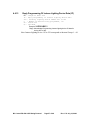
Request Programming Of Insteon Lighting Device Data (ip)............................................................ 33
Request Keypad Area Assignments (KA) .................................................................................34
4.20.1
4.20.2
4.21
Send Installer Mode Exited (IE) ........................................................................................................ 31
Insteon Lighting Systems for the M1XSP Serial Port Expander (IR)...................................32
4.19.1
4.19.2
4.19.3
4.19.4
4.19.5
4.20
Send Valid Or Invalid User Code Format (IC) .................................................................................. 30
Installer Program Mode Exited (IE) .........................................................................................31
4.18.1
4.19
Send Email Trigger Data (EM).......................................................................................................... 29
Send Valid User Number And Invalid User Code (IC) ...........................................................30
4.17.1
4.18
Send Entry/Exit Data (EE)................................................................................................................. 28
Email Trigger (EM) ....................................................................................................................29
4.16.1
4.17
Request Lighting Device Status (ds).................................................................................................. 28
Reply Lighting Device Status Data (DS) ........................................................................................... 28
Request Keypad Function Key Press (kf) .......................................................................................... 36
Reply Keypad Function Key Press (KF)............................................................................................ 36
System Log Data Update (LD) ...................................................................................................37
4.23.1
Request System Log Data (ld) ........................................................................................................... 37
M1 Control RS-232 ASCII String Protocol
Page 3 of 68
Rev. 1.79 July 16, 2009
4.23.2
4.24
Zone Temperature And Keypad Temperature (LW)..............................................................38
4.24.1
4.24.2
4.25
Request Temperature Data (lw) ......................................................................................................... 38
Reply Temperature Data (LW) .......................................................................................................... 38
Power Line Carrier (PLC) Data (PC) .......................................................................................39
4.25.1
4.25.2
4.25.3
4.25.4
4.25.5
4.25.6
4.25.7
4.26
Request Write Log Data (le) .............................................................................................................. 38
Control Any PLC Device (pc) ........................................................................................................... 39
PLC Change Update (PC).................................................................................................................. 39
Turn OFF PLC Device (pf)................................................................................................................ 40
Turn ON PLC Device (pn)................................................................................................................. 40
Request PLC status (ps) ..................................................................................................................... 40
Returned PLC status (PS) .................................................................................................................. 41
Toggle PLC Device (pt)..................................................................................................................... 41
Reset Ethernet Module (RE) ......................................................................................................41
4.26.1
Reset Ethernet IP Address(RE).......................................................................................................... 41
4.27
ELKRP Connected (RP).............................................................................................................42
4.28
Real Time Clock (RR).................................................................................................................42
4.28.1
4.28.2
4.28.3
4.29
ASCII String Text Descriptions (SD) ........................................................................................43
4.29.1
4.29.2
4.29.3
4.30
Request System Trouble Status (ss)................................................................................................... 44
Reply System Trouble Status (SS)..................................................................................................... 44
Request Temperatures (ST) .......................................................................................................46
4.31.1
4.31.2
4.32
Request ASCII String Text Descriptions (sd).................................................................................... 43
Reply With ASCII String Text Descriptions (SD)............................................................................. 43
Type Table for Text Descriptions: ..................................................................................................... 44
System Trouble Status (SS)........................................................................................................44
4.30.1
4.30.2
4.31
Request Real Time Clock Data (rr).................................................................................................... 42
Reply Real Time Clock Data (RR) .................................................................................................... 42
Write Real Time Clock Data (rw)...................................................................................................... 42
Request Temperature format (st) ....................................................................................................... 46
Reply With Requested Temperature (ST).......................................................................................... 46
System Word Messages (sp) .......................................................................................................47
4.32.1
4.32.2
Speak Word at Voice/Siren Output (sw)............................................................................................ 47
Speak Phrase at Voice/Siren Output (sp) ........................................................................................... 47
4.33
Tasks Change Update (TC) ........................................................................................................47
4.34
Task Activation (tn) ....................................................................................................................47
4.34.1
4.35
Thermostat Control (TR) ...........................................................................................................48
4.35.1
4.35.2
4.35.3
4.35.4
4.35.5
4.36
Request Thermostat Data (tr)............................................................................................................. 48
Reply Thermostat Data (TR).............................................................................................................. 48
Set Thermostat Data (ts) .................................................................................................................... 48
Request - Omnistat 2 From PC to M1 ASCII Protocol (t2) ............................................................... 49
Reply - M1 to PC with Omnistat 2 ASCII Hex data (T2).................................................................. 49
Version Number of M1 and M1XEP (VN) ..............................................................................50
4.36.1
4.36.2
4.37
Task Flag Activation.......................................................................................................................... 48
Request M1 Version Number (vn)..................................................................................................... 50
Reply M1 Version Number (VN) ...................................................................................................... 50
Request Valid User Code Areas (UA) .......................................................................................51
4.37.1
4.37.2
Request Valid User Code Areas (ua) ................................................................................................. 51
Reply With Valid User Code Areas (UA).......................................................................................... 51
M1 Control RS-232 ASCII String Protocol
Page 4 of 68
Rev. 1.79 July 16, 2009
4.38
Zone Change Update (ZC) .........................................................................................................51
4.39
Zone Status Messages (ZB) ........................................................................................................53
4.39.1
4.39.2
4.39.3
4.39.4
4.39.5
4.39.6
4.39.7
4.40
Zone Definition (ZD)...................................................................................................................55
4.40.1
4.40.2
4.40.3
4.41
Zone Bypass Request (zb) ................................................................................................................. 53
Reply With Bypassed Zone State (ZB).............................................................................................. 53
Zone Partition Request (zp) ............................................................................................................... 53
Zone Partition Report (ZP) ................................................................................................................ 53
Zone Status Request (zs).................................................................................................................... 54
Zone Status Report (ZS) .................................................................................................................... 54
Zone Status Table .............................................................................................................................. 54
Request Zone Definition (zd)............................................................................................................. 55
Reply Zone Definition Data (ZD)...................................................................................................... 55
Zone Definition Number List: Character - Definition Number ......................................................... 56
Zone Analog Voltage (ZV) .........................................................................................................56
4.41.1
4.41.2
4.41.3
Request Zone Voltage (zv) ................................................................................................................ 56
Reply Zone Analog Voltage Data (ZV) ............................................................................................. 56
Reply Programming Of Insteon Lighting Device Data (IP)............................................................... 57
5. Interpreting M1/EZ8 Event Log Extended Data
Information....................................................................... 58
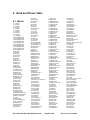
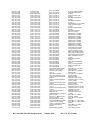
6. Word And Phrase Table .......................................... 60
6.1
Words ...........................................................................................................................................60
6.2
Phrases .........................................................................................................................................61
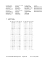
7. ASCII Table ............................................................... 63
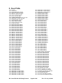
8. Event Table ............................................................... 64
9. Calculate Checksum................................................ 67
10. Contact Information: ............................................. 68
M1 Control RS-232 ASCII String Protocol
Page 5 of 68
Rev. 1.79 July 16, 2009
M1 Command Summary
Lower case is command to control.
Upper case is data from control.
a0 – Disarm
a1 – Arm to away
a2 – Arm to stay
a3 – Arm to stay instant
a4 – Arm to night
a5 – Arm to night instant
a6 – Arm to vacation
a7 – Arm step to next Away Mode
a8 – Arm step to next Stay Mode
AP – Send ASCII String
ar – Alarm Reporting Acknowledge
AR – Alarm Reporting to Ethernet
as – Request arming status
AS – Arming status report data
at – Ethernet Test Acknowledge
AT – Ethernet Test to IP
az – Alarm by zone request
AZ – Alarm by zone reply
ca – Request Touchscreen audio command
CA –Reply Touchscreen audio command
CC – Control output change update
cd – Incoming Audio Equip Command
CD – Outgoing Audio Equip Command
cf – Control output OFF
cn – Control output ON
cp – Request ALL custom values
cr – Request custom value
CR – Custom value report data
cs – Control output status request
CS – Control output status report data
ct – Control output TOGGLE
cu – Change user code request
CU – Change user code reply
cw – Write custom value data
cv – Request Counter value
CV – Counter Value Data
cx – Write counter value
dm – Display message
ds – Lighting Poll Request
DS – Lighting Poll Response
DK- Display KP LCD Data, not used
M1 Control RS-232 ASCII String Protocol
EE – Entry/Exit Time Data
EM – Email Trigger to M1XEP
IC – Send invalid user code digits
IE – Installer program exited
IP- M1XSP Insteon Program
ip- M1XSP Insteon Program
IR- M1XSP Insteon Read
ir- M1XSP Insteon Read
ka – Request keypad areas
KA – Keypad areas report data
kc – Request F Key illumination status
KC – Keypad key change update
kf – Request simulated function key press
KF – Function key pressed data
LD – Log data with index
ld – Request log data, with index
le – Write Log Data Entry
lw – Request temperature data
LW – Reply temperature data
NS – Reply Source Name
NZ – Reply Zone Name
pc – Control any PLC device
PC – PLC change update
pf – Turn OFF PLC device
pn – Turn ON PLC device
ps – Request PLC status
PS – PLC status report data
pt – Toggle PLC device
RE – Reset Ethernet Module
RP – ELKRP connected
rr – Request Real Time Clock Read
RR – Real Time Clock Data
rs – Used by Touchscreen
rw – Real Time Clock Write
sd – Request text string descriptions
SD – Text string description report data
sp – Speak phrase
Page 6 of 68
Rev. 1.79 July 16, 2009
ss –Request System Trouble Status
SS – System Trouble Status data
st – Request temperature
ST – Temperature report data
sw – Speak word
t2 – Request Omnistat 2 data
T2 – Reply Omnistat 2 data
TC – Task change update
tn – Task activation
tr – Request thermostat data
TR – Thermostat data report
ts – Set thermostat data
ua – Request user code areas
UA – User code areas report data
vn – request Version Number of M1
VN – Reply Version Number of M1
XB – reserved by ELKRP
xk – Reply from Ethernet test
XK – Request Ethernet test
zb – Zone bypass request
ZB – Zone bypass report data
ZC – Zone change update
zd – Request zone definition data
ZD – Zone definition report data
zp – Zone partition request
ZP – Zone partition report data
zs – Zone status request
ZS – Zone status report data
zv –Request Zone analog voltage
ZV – Zone analog voltage data
Revision History:
Rev. 0.1 - 1/13/04 – Changed Task Number ASCII reply from 2 digits to 3 digits and changed
command from “R” to “T”.
Rev. 0.2 – 2/17/04 – Added Keypad key pressed ASCII transmission.
Rev. 0.3 – 3/23/04 – Changed Tasks from a state on/off to a one-shot button.
Rev. 1.1 – 3/24/04 – Removed ON/OFF Task commands.
Rev. 1.2 – 3/25/04 – Added Request ASCII Names to protocol.
Rev. 1.3 – 3/29/04 – Added Request Temperatures
Rev. 1.4 – 3/30/04 – Added Keypad Key Change, word and phrase table to specification.
Rev. 1.5 – 4/15/04 – Added Read and Write Custom Values to protocol.
Rev. 1.6 – 6/07/04 – Added note about high bit of ASCII names may be set to indicate “Show On
Keypad”.
Rev. 1.7 – 6/15/04 – Added Request for User Code valid areas.
Rev. 1.8 – 6/28/04 – Task Change typo - Command from RC to TC, status byte set to 0.
Rev. 1.9 – 7/12/04 – Added All_Lights_On, All_Lights_Off, All_Units_Off to PLC Update for
Serial Port Expander and Zensys
Rev. 1.10 – 7/16/04 – Request and return for what area a keypad is valid in, ability to activate
keypad function key, ability to bypass a zone.
Rev. 1.11 – 7/19/04 – Added Request Function Key names, Request Keypad Areas, Activate
Keypad function keys, bypass a zone, send arming status on keypad
arm/disarm.
Rev. 1.12 – 8/4/04 – Changed Zone Temperature Probe subtract value to 60 from 40.
Rev. 1.14 - 8/6/04 – Document correction in Log Data command, changed NQ to LD.
Added PLC Status example.
Rev. 1.15 – 8/20/04 – Added ASCII Thermostat control.
M1 Control RS-232 ASCII String Protocol
Page 7 of 68
Rev. 1.79 July 16, 2009
Rev. 1.16 – 8/24/04 – Added Thermostat Humidity support
Rev. 1.17 – 8/27/04 – Enhanced Arming Status Request, Added Zone Definition data.
Rev. 1.18 – 9/21/04 – Requesting Names, sd command, returns name whose first character is >
“space” or last name in name array.
Rev. 1.19 – 10/15/04 – Added checksum C code routines.
Rev. 1.20 – 10/22/04 – PLC reply, “PS” command, replies with light level value to 48 (0x30)
added to the value.
Rev.1.21 – 10/26/04 – Added ‘*’ key to “4.21 Keypad Function Key Press”, fixed task number to
3 digits in “Task Change Update”.
Rev. 1.22 – 11/15/04 – Added Type of data to the Custom Values response. Implemented factory
use data to Request Valid User Code Areas.
Rev. 1.23 – 12/09/04 – Corrected length of request and reply temperature data, command “st” and
“ST”.
Rev. 1.24 – 12/17/04 – Added command summary
Rev. 1.25 – 1/5/05 – Added email trigger, “EM”, command
Rev. 1.26 – 1/11/05 – Modified “KC” command to add keypad function key LED status.
Rev. 1.27 – 1/12/05 – Corrected length of alarm reporting acknowledge from 04 to 06.
Rev. 1.28 – 1/12/05 – Corrected Alarm report acknowledge command AR to ar, added Alarm Test
AR and at commands, fix Task Change Update length to 0x0A
Rev. 1.29 – 1/17/05 – Added “IE” Installer Program Mode Exited.
Rev. 1.30 – 1/31/05 – Changed “IC” Invalid User Code from 6 digits to 12 digits data for 26 bit
Weigand prox card data. Added Zone Analog Voltage Data Request
command.
Rev. 1.31 – 2/21/05 – Corrected Alarm Reporting packet length in description from 21 to 22 bytes.
Rev. 1.32 – 2/22/05 – Added “kc” command to request keypad F key illumination status. Returns
“KC” command data.
Rev. 1.33 – 3/16/05 – Added Armed Away Mode stepping and Armed Stay Mode stepping. “a7”
& “a8” commands. Added number of user code digits to “UA” command.
Added “XK” and “xk” command for Ethernet Module Test.
Rev. 1.34 – 3/17/05 – Fixed “Reply Thermostat Data (TR)” description. Added automatic
temperature updates on change. Version 4.2.8
Rev. 1.35 – 3/24/05 – Added byte to indicate if code required to bypass in the “KC” command.
Rev. 1.36 – 4/28/05 – Fixed error in length of Custom Value Reply. Version 4.3.1
Rev. 1.37 – 5/2/05 – “SD” command, explain the search for names to be returned. Explained dims,
brights, and preset dim in “pc” command.
Rev. 1.38 – 5/11/05 – “RR” command to request and write real time clock data added to protocol.
Rev. 1.39 – 5/12/05 - Added if in Daylight Savings Time Mode to “RR” command. Added ‘C’
character to “kf” command to control chime.
Rev. 1.40 – 5/20/05 Changed “IC” command so that valid user code number is broadcast.
Rev. 1.41 – 5/23/05 Fixed “pf” documentation’s example code.
Rev. 1.42 – 5/26/05 Added Real Time Clock time data to “XK” command and corrected
response in document.
Rev. 1.43 – 6/2/05
Documented the “RP” command which is sent from XEP upon ELK RP
connection. Added clock and date display mode to the “XK” command.
Added Chime Mode status to “KF” command
M1 Control RS-232 ASCII String Protocol
Page 8 of 68
Rev. 1.79 July 16, 2009
Rev. 1.44 – 6/7/05
Added the “ld”, request log data command and added the index number to
the “LD” log data command.
Rev. 1.45 – 6/10/05 Added day of week and year to “LD” log data reply.
Rev. 1.46 - 6/16/05 Added Keypad Number to “IC” command. Added Event Table.
Rev. 1.47 – 6/30/05 Added lw and LW command to request temperature sensor and keypad
temperature.
Rev. 1.48 – 7/12/05 Added M1SDK software documentation.
Rev. 1.49 – 8/15/05 Corrected length of “ZC” example. Added “cp” command to request all
custom values.
Rev. 1.50 – 8/22/05 Added user code type to “UA” reply. Added “RE” Command to reset
Ethernet Module. Ver. 4.3.7
Rev. 1.51 – 12/5/05 Added “ds” and “DS” for lighting device poll. This command is only used
by the M1XSP Serial Port Expander. Added “cu”, “CU” change user code.
Rev. 1.52 – 12/9/05 Added ‘F’ or ‘C’ to UA command for Fahrenheit or Celcius temperature
mode. Added “az” and “AZ” alarm by zone commands
Rev. 1.53 – 12/22/05 Added ability to program what areas the user code is valid in on the “CU”
command.
Rev. 1.54 – 2/03/06 Add response on “cu” command that if code to be programmed is a duplicate
and denied, the returned user code is 255.
Rev. 1.55 – 3/03/06 Documented softbypass in ZS command.
Rev. 1.56 – 3/21/06 Added Entrance and Exit time to AS command.
Rev. 1.57 – 5/26/06 Added M1XSP remote programming for Insteon Setup.
Rev. 1.58 – 6/1/06 Changed number of packets from 9 to 8 on Insteon Setup. Added Null Modem.
Rev. 1.59 – 6/5/06 Added RP documentation.
Rev 1.60 – 10/26/06 Corrected “IC” command user numbers
Rev.1.61 – 07/02/07 Correct number of user names of reading user names from 99 to 199.
Added “le” command to force log entry for dialer reporting. M1 version 4.1.2 and
5.1.2 or later.
Rev. 1.6.2 – 08/21/07 Added “SS” command to poll for system troubles.
Rev. 1.6.3 – 08/24/07 Added code restriction disable/enable to the “cu” command.
Rev. 1.6.5 – 11/27/07 – “ZC” documentation clarification.
Rev. 1.6.6 – 12/12/2007 – “SS” further explained fire trouble zone decode.
Rev. 1.6.7 – 3/19/2008 – Fixed documentation error in the “AZ” command.
Rev. 1.6.8 – 5/2/2008 – Added in “ts” ASCII thermostat command the ability to set the thermostat
temperature from a controller with a thermostat connected to it.
Rev. 1.6.9 – 5/6/2008 – Added “CV”, “cv”, “cx” command to read and write counter values.
Rev. 1.70 – 6/20/2008 – Fixed documentation error on “CR” command using the “NN” value.
Rev. 1.71 – 10/10/2008 - Added “Interpreting M1/EZ8 Event Log Extended Information”.
Rev. 1.72 – 10/27/2008 – Added “AP” commands to send ASCII strings to outside IP address.
Added “CD” commands to control audio equipment.
Remapped document by commands.
Rev. 1.73 – 10/29/2008 – Corrected “Interpreting M1/EZ8 Event Log Extended Information”
involving extended function key code from 500 to 400 range.
Rev. 1.74 – 11/06/2008 – Added Omnistat 2 documentation, added SD commands 18 & 19, EE
command, CA command. VN version number. Version 5.1.12 or later
Rev. 1.75 – 11/14/2008 – Modified the CA and CD commands.
M1 Control RS-232 ASCII String Protocol
Page 9 of 68
Rev. 1.79 July 16, 2009
Rev. 1.76 - 4/21/2009 – Modified XK description.
Rev. 1.77 – 5/04/2009 – Modified EE command to add Armed State to command string.
Rev. 1.78 – 7/08/2009 – Removed ASCII audio commands (CD) and use numbers in command
strings
Rev. 1.79 – 7/16/2009 – Explained the SS command of extracting zone troubles from string.
M1 Control RS-232 ASCII String Protocol
Page 10 of 68
Rev. 1.79 July 16, 2009
1. General
This document describes the protocol specifications for the ELK M1 Security and
Automation Controller’s RS232 serial interface port and related controls including the ELK
EZ8 Control. This port allows communications between the M1 and various ‘third party’
devices such as computers, lighting, HVAC, and many types of automation devices on a realtime basis.
Connection to the port is via a 9-pin “DB-9” cord. You can use any PC connected to the
RS232 port to communicate with the control panel. You can use any software capable of
sending ASCII strings through your PC’s COM ports.
2. Electrical/Mechanical Specifications
The interface connector supports a limited RS-232 hardware interface configured as DCE
(Data Communication Equipment). The pin-outs are GND – Pin 5, and the TXD – Pin 2, RXD
– Pin 3 signals. The control panel ignores all handshake lines when sending data, so connected
equipment must be capable of receiving continuous 9600 to 115,200 baud data.
To connect to a computer use as straight through serial cable. To connect to other DCE
configured serial ports, a null modem and maybe a gender changer will be required.
Communication settings should be 9600 to 115,200 baud, 8 data bits, no parity, and one
stop bit. Logic levels at the interface are standard RS-232. The interface is full duplex. Baud
rates must be set in the M1 Global programming section.
3. Error Checking
The transmission contains checksum and packet length error checking. No acknowledge or
re-transmission capability is implemented.
M1 Control RS-232 ASCII String Protocol
Page 11 of 68
Rev. 1.79 July 16, 2009
4. Messages
With the exception of the message terminator, CR-LF, all characters are printable ASCII.
See Appendix for an example of C source for generating a well-formed message string.
A packet length and checksum generator program is available from ELK Products, Inc. to
generate test ASCII packets. The program is called M1_SDK.exe.
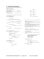
4.1 Data Packet Format
Data packets both from a PC to the control panel and from the control panel to a PC use
the following format.
NNMSD...OO CC (CR-LF )
ASCII hexadecimal Notation - 0x00 to 0xFF, the 0x.. Represents ASCII hexadecimal notation
4.1.1 Packet Length
NN
2 ASCII characters, length of packet including all characters except Length and CRLF at the end of the packet. Legal values are ASCII hex 00 to FF. Permissible characters are
ASCII 0-9 and upper case A-F.
4.1.2 Message Type
M
1 ASCII character, message/packet type ID. These are upper and lower case alpha
characters. Upper case is used for responses from the control panel and lower case for
commands to the control panel. Allowed values are a-z and A-Z
4.1.3 Sub-Message Type
S
ASCII character, sub-message/packet type. These are upper and lower case alpha
characters. Upper case is used for responses from the control panel and lower case for
commands to the control panel. Allowed values are 0-9, a-z and A-Z.
4.1.4 Data
D...
0 or more ASCII characters of data associated with the command/packet type. Any
printable ASCII character is permitted. L, P is part of the Data packet as explained when
needed.
4.1.5 Reserved
00
Two ASCII characters, reserved for future development. The only currently legal
character is 0 (ASCII zero).
4.1.6 Checksum
CC
2 ASCII characters, 2-digit checksum. This is the hexadecimal two’s complement
of the modulo-256 sum of the ASCII values of all characters in the message excluding the
checksum itself and the CR-LF terminator at the end of the message. Permissible characters are
ASCII 0-9 and upper case A-F. When all the characters are added to the Checksum, the value
should equal 0.
M1 Control RS-232 ASCII String Protocol
Page 12 of 68
Rev. 1.79 July 16, 2009
4.1.7 Terminator
(CR-LF)
Message terminator. ASCII characters consisting of hexadecimal 0x0D and
0x0A. The 0x0A is optional. A message terminator may also use the 0x0A only.
NNMSD...0 0 CC (CR-LF ) packet protocol
4.1.8 Message Processing Time:
The M1’s incoming message buffer can hold up to 250 characters. Control messages take
different times to process messages: Lighting control messages may take up to 500 ms to
process the message and send it to a M1XSP Serial Port Expander if it is used. The M1XSP
can buffer two control messages. Some of the lighting control systems have status feedback
with failure retries which may take 2 to 3 seconds to transmit to a faulty light control signal.
Note: In the examples below, the data portion will be in Bold text. The packet length and
checksum will not be in bold.
4.2 Arm and Disarm Messages (a0..a8)
For Arm and Disarm messages the data field aLPDDDDDD consists of:
aL P DDDDDD Example: 0D a1 1 003456 00 37
L = Arming Level. Range: 0 to 8.
0 = Disarm
1 = Armed Away
2 = Armed Stay
3 = Armed Stay Instant
4 = Armed Night
5 = Armed Night Instant
6 = Armed Vacation
7 = Arm to next Away Mode Version 4.2.8 or later
8 = Arm to next Stay Mode
Version 4.2.8 or later
P = Partition or Area 1 to 8
DDDDDD = six digits for the User Code. If using four digits as the code length, precede
the code with 0’s, ex. 1234 would be 001234.
Note: Arming the control panel with zones open will initiate “force arming” regardless of
whether force arming is enabled or disabled in the control panel.
Arm / Disarm Examples
4.2.1 Disarm (a0)
0Da010034560038(CR-LF)
Example: a0=Disarm, 1=Area 1, 003456=User Code 3456.
M1 Control RS-232 ASCII String Protocol
Page 13 of 68
Rev. 1.79 July 16, 2009
4.2.2 Arm to Away (a1)
0Da11001234003F(CR-LF)
Example: a1=arm away, 1=Area 1, 001234=User Code 1234.
4.2.3 Arm to Stay (Home) (a2)
0Da23005678002C(CR-LF)
Example: a2=arm stay, 3=Area 3, 005678=User Code 5678.
4.2.4 Arm to Stay Instant (a3)
0Da380056780026(CR-LF)
Example: a3=arm stay instant, 8=Area 8, 005678=User Code 5678.
4.2.5 Arm to Night (a4)
0Da480056780025(CR-LF)
Example: a4=arm night, 8=Area 8, 005678=User Code 5678.
4.2.6 Arm to Night Instant (a5)
0Da580056780024(CR-LF)
Example: a5=arm night instant, 8=Area 8, 005678=User Code 5678.
4.2.7 Arm to Vacation (a6)
0Da680056780023(CR-LF)
Example: a6=Vacation, 8=Area 8, 005678=User Code 5678.
4.2.8 Arm, Step To Next Away Mode (a7)
0Da710034560031 (CR-LF) Version 4.2.8 or later.
Example: a7=Step to next Away arming mode, 1=Area 1, 003456=User Code 3456.
4.2.9 Arm, Step To Next Stay Mode (a8)
0Da810012340038 (CR-LF) Version 4.2.8 or later.
Example: a8=Step to next Stay arming mode, 1=Area 1, 001234=User Code 1234.
You can send a request to the control panel for its arming status by sending an Arming Status request.
The Control panel will respond with an Arming Status Report.
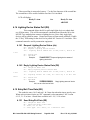
4.2.10 Arming Status Request (as)
06 – Length as ASCII hex
as – Request arming status
00 – future use
CC – Checksum
M1 Control RS-232 ASCII String Protocol
Page 14 of 68
Rev. 1.79 July 16, 2009
Example:
06as0066(CR-LF) Request Arming status
The control panel responds to this message with an Arming Status Report
4.2.11 Reply Arming Status Report Data (AS)
1E – Length as ASCII hex
AS – Reply with zone definition data
S[8] - Array of 8 area armed status.
U[8] - Array of 8 area arm up state.
A[8] - Array of 8 area alarm state.
00 – future use, M1 Version 4.11 and later, contains the first
found Exit time if U[x] = ‘3’ or Entrance time if A[x] = ‘1’ as
two digits hex in seconds.
CC – Checksum
Example:
1EAS100000004000000030000000000E Area 1 is armed
away, and the area is in full fire alarm.
Example: 1EAS1000000031111111000000000902 Exit time set to 9 seconds.
If the control’s area status changes, this message will be sent if Global Option “Transmit Keypad Keys” is
enabled.
“S” 8-character array field, represents the arming status of partitions 1-8. The leftmost “S” is Area 1.
Each area or partition field can contain one of the following ASCII values:
‘0’
Disarmed
‘1’
Armed Away
‘2’
Armed Stay
‘3’
Armed Stay Instant
‘4’
Armed to Night
‘5’
Armed to Night Instant
‘6’
Armed to Vacation
“U” 8-character array field, represents the arm up state of partitions 1-8. The leftmost “U” is Area 1.
Each area or partition field can contain one of the following ASCII values:
‘0’
Not Ready To Arm
‘1’
Ready To Arm
‘2’
Ready To Arm, but a zone is violated and can be Force Armed.
‘3’
Armed with Exit Timer working
‘4’
Armed Fully
‘5’
Force Armed with a force arm zone violated
‘6’
Armed with a bypass
“A” 8-character array field, represents the current alarm state of partitions 1-8. The leftmost “A” is
Area 1. Each area or partition field can contain one of the following ASCII values:
‘0’
No Alarm Active
‘1’
Entrance Delay is Active
‘2’
Alarm Abort Delay Active
‘3’ to ‘B’
Area is in Full Alarm, see ASCII alarm table values below:
FireAlarm = ‘3’,
MedicalAlarm = ‘4’,
PoliceAlarm = ‘5’,
BurglarAlarm = ‘6’,
Aux1Alarm = ‘7’,
Aux2Alarm = ‘8’,
M1 Control RS-232 ASCII String Protocol
Page 15 of 68
Rev. 1.79 July 16, 2009
Aux3Alarm = ‘9’, //not used
Aux4Alarm = ‘:’, //not used
CarbonMonoxideAlarm = ‘;’,
EmergencyAlarm = ‘<’,
FreezeAlarm= ‘=’,
GasAlarm = ‘>’,
HeatAlarm = ‘?’,
WaterAlarm = ‘@’,
FireSupervisory = ‘A’,
VerifyFire = ‘B’,
4.3 Send ASCII String To IP Address(AP)
The AP command allows you to send a custom ASCII string message via
TCP/IP to a specific IP address on a specific port. To accomplish this,
you need to create a TEXT string in the Automation/Text section of ELKRP
which is stored in the M1. This text string will consist of the message
to send plus some destination information.
One of the eight Central Station IP Receiver addresses programmed in
the M1XEP must be used (Central Station tab on the M1XEP Setup dialog in
ElkRP). If used for this command, that IP address may not be used for
reporting alarms and other events to a Central Station.
To enter the Central Station's IP address on the M1XEP Setup dialog in
ElkRP, a "Telephone Number" must be enabled with a "Reporting Format" of
"6 = Ethernet M1XEP". Since this Telephone Number cannot be used for
reporting alarms and other events MAKE certain to uncheck all Area blocks
as well as the Events to be reported blocks on this screen.
Then create a TEXT string and store it in the M1’s Automation/Text
section:
00APxDDDD…{up to 200 ASCII chars here}CRLF
00 - two zeros. Any two digits will work, but they are ignored.
AP - Command to send text string.
x - ASCII "1" - "8". This tells the M1XEP which Central Station IP
address to use. Corresponds to Telephone 1-8.
DDDD… - ASCII text data
CRLF - Carriage Return/Line Feed
EXAMPLE: 00AP4Sprinkler 1 ON^M^J
Build a text string and store in the M1’s
Automation/Text section using ELKRP. “^M^J” is a carriage return/line
feed.
The example will send “Sprinkler 1 ON” to the IP address programmed as telephone number 4.
Write a RULE to send this text string out serial port 0. When the
M1XEP receives it, it will broadcast it to all current connected devices.
The entire string will be included in the local broadcast. Then the
M1XEP will look up the specified Central Station IP address/port and
send only the ASCII message in a TCP packet to that address/port.
Special Case:
If the first character of the text string message is an ASCII “3”,
the M1XEP will insert zone status of all 208 zones at the end of the
remaining ASCII message (if any characters follow the “3”) and before the
M1 Control RS-232 ASCII String Protocol
Page 16 of 68
Rev. 1.79 July 16, 2009
CR/LF. The Zone Status is 208 bytes and is identical to the “data”
portion of the “ZS” ASCII command.
EXAMPLE: 00AP43SendingZoneStatus^M^J
Packet Data: SendingZoneStatus(208 bytes of ZS zone status) (CR-LF)
4.4 Ethernet Central Station Reporting (AR)
4.4.1
Alarm Reporting (AR)
Reporting of alarms through the built on serial port 0 consists of an ASCII string following
the same data format of the digital dialer’s Contact ID transmission. Programming one of
the telephone numbers with a dialer format set to “Ethernet” will enable the transmissions
of the alarm ASCII strings over the RS-232 serial port 0. Available in M1 Version 4.2.8
and after.
16ARAAAAAACCCCGGZZZT00CC<cr><lf>
16 – Length as ASCII hex, 22 bytes
AR – Alarm Reporting Command
AAAAAA – Account Number, 6 ASCII digits
CCCC - Alarm Code consists of 4 ASCII digits.
GG - Group/Partition Number consisting of 2 ASCII digits.
ZZZ - Zone/User Number consisting of 3 ASCII digits.
T – IP Address to send alarm on. Valid 1 to 8 on M1 Gold, 1 to 4 on M1 Standard and Ez8.
00 - Future use 2 digits.
CC – checksum
Example: 16 AR 123456 1134 01 001 1 00 85 - Length 22 bytes, AR alarm reporting,
account 123456, CID – Burglar Entry/Exit 1, Area 01, Zone 001, use telephone/IP address
1. Spaces are for readability only.
4.4.2 Alarm Report Acknowledge (ar)
The Ethernet Module (M1XEP) will acknowledge the M1’s Alarm Report transmission
with the reply: 06ar0067<cr><lf>. This acknowledge is sent to the M1 only if the central
station’s server acknowledges the Ethernet Module’s data packet.
4.4.3 Alarm Reporting Test (AT)
The Alarm Reporting Test string is sent every 15 minutes from the M1 as a keep alive
message to the M1XEP Ethernet Module along with which IP address to test. All IP addresses
are set into the M1XEP module.
07 – Length as ASCII hex, 7 bytes
AT – Alarm Reporting Command
T – IP Address to test, 1-8
00 - Future use 2 digits.
CC – checksum
M1 Control RS-232 ASCII String Protocol
Page 17 of 68
Rev. 1.79 July 16, 2009
Example: 07 AT 1 00 73 Send keep alive signal to the M1XEP and test IP address 1. Spaces
are for readability only.
4.4.4 Alarm Reporting Test Acknowledge (at)
If the Alarm Reporting Test if successful to the central station’s IP address the
Acknowledge message will be sent to the M1 from the M1XEP: 06at0065<cr><lf>.
4.4.5 Ethernet Module Test (XK)
The “XK” command is automatically sent every 30 seconds. This is done regardless of
whether an M1XEP Ethernet Module is present or not. The XK command serves two
purposes. 1) It tests to see if a M1XEP Ethernet Module is connected to the Control. 2) It
includes the Control’s real time clock information (current Date and Time) for general purpose
use, including but not limited to clock synchronization by a third party device..
The expected response from a connected M1XEP Ethernet Module is “xk”. However, the
Control does not actually care or keep track of a missing “xk” response UNLESS or UNTIL
after a M1XEP Ethernet Module has been properly enrolled with the Control. This can be
accomplished via the Bus Module Enrollment process (Keypad programming Menu 1) or by
the RP software). Once an M1XEP has been enrolled, the Control will now begin tracking
each response to an “XK” command, and it will display and log an “Ethernet Trouble”
message if an “xk” response is not received within 120 seconds of the “XK” command. This
response scenario is also true for alarm reporting commands “AT” and “AR”. Basically, the
M1XEP will withhold sending the “xk” response if it should fail to complete an alarm or
restoral transmission after 2 attempts. This allows for 1 transmission miss.
NOTE: Control Firmware Version 4.32 and after includes the M1’s real time clock
information.
16 – Length as ASCII hex, 22 bytes
XK – Test Ethernet Module is alive
ss – second as two ASCII characters decimal, “00” to “59”
mm – Minute as two ASCII characters decimal, “00” to “59”
hh – Hour as two ASCII characters decimal, “00” to “23” 24 hour
D – Day of week as one ASCII character, “1”=Sunday to “7”=Saturday
DM – Day of month as two ASCII characters decimal, “01” to “31”
MM – Month as two ASCII characters decimal, “01” to “12”
YY – Year as two ASCII characters decimal, “00” to “99” as in 2099
S - Daylight Savings Time: “0”=Not active, “1”= Active.
C - Clock Mode as one ASCII character, ‘1’ = 12 hour, 0 = 24 hour time mode
T - Date Display Mode as one ASCII character, 0 = mm/dd, 1 = dd/mm
00 - Future use 2 digits.
CC – checksum
Example: 16XK2636115020605110006F test signal to the M1XEP module. Real Time Clock
Value = Thursday, 11:36:26 PM, June 2, 2005, Daylite savings is active for this time of year,
Clock display mode is 12 hour, Date display mode is month/day.
4.4.6 Ethernet Module Test Acknowledge (xk)
If the Ethernet Module is alive, it will reply back to the M1 with: 06xk0057<cr><lf>.
M1 Control RS-232 ASCII String Protocol
Page 18 of 68
Rev. 1.79 July 16, 2009
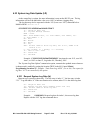
4.5 Alarm By Zone Request (AZ)
06
az
00
CC
–
–
–
–
Length as ASCII hex
M1 version 4.3.9 and later
Request alarm by zone
future use
Checksum
Example:
06az005F (CR-LF)
Request alarm by zone
The control panel responds to this message with an Alarm By Zone Report
4.5.1
Reply Alarm By Zone Report Data (AZ)
D6 – Length as ASCII hex
M1 version 4.3.9 and later
AZ – Reply with zone definition data
Z[208] - Array of 208 bytes showing alarm by zone. A value
of ‘0’ or 0x30 indicates the zone is not in alarm. A value greater
than ‘0’ indicates the zone has been triggered into alarm. The zone
value will be reset back to ‘0’ when an authorization code is entered
to acknowledge the alarm. The value in the zone byte is the same as
the zone function value plus 0x30 or 48. See table below.
00 – future use
CC – Checksum
Zone Definitions in Alarm By Zone string:
Disabled = ‘0’
Burglar Entry/Exit 1 = ‘1’
Burglar Entry/Exit 2 = ‘2’
Burglar Perimeter Instant = ‘3’
Burglar Interior = ‘4’
Burglar Interior Follower = ‘5’
Burglar Interior Night = ‘6’
Burglar Interior Night Delay = ‘7’
Burglar 24 Hour = ‘8’
Burglar Box Tamper = ‘9’
Fire Alarm = ‘:’
Fire Verified = ‘;’
Fire Supervisory = ‘<’
Aux Alarm 1 = ‘=’
Aux Alarm 2 = ‘>’
Key fob = ‘?’ //not used
Non Alarm = ‘@’ //not used
Carbon Monoxide = ‘A’
Emergency Alarm = ‘B’
Freeze Alarm = ‘C’
Gas Alarm = ‘D’
Heat Alarm = ‘E’
Medical Alarm = ‘F’
Police Alarm = ‘G’
Police No Indication = ‘H’
Water Alarm = ‘I’
Subtract 0x30 or 48 from the ASCII value to get the
numeric decimal value.
Example:
D6AZ00000000900000000000000000000000000000000000000000000000000000000
0000000000000000000000000000000000000000000000000000000000000000000000
0000000000000000000000000000000000000000000000000000000000000000000000
0000082
Zone 9 is in alarm and is defined as a “Burglar Box Tamper” zone definition 9 + 0x30 or 57
decimal.
M1 Control RS-232 ASCII String Protocol
Page 19 of 68
Rev. 1.79 July 16, 2009
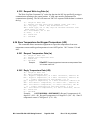
4.6 Touchscreen Audio Command (CA)
This command is used by the touchscreens to request audio status data from the
M1XEP for audio control display. It is not used by the M1. The M1XEP intercepts
the command packet and sends translated commands to the audio equipment. This
command is available on ELKRMS touchscreen software.
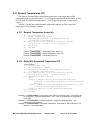
4.6.1
Request Audio Data (ca)
08
ca
NN
00
CC
–
–
–
–
–
Length as ASCII hex
Read custom value
Which zone to request data on. ASCII decimal value
future use
Checksum
Example: 08ca010003 Request audio zone 1 data.
4.6.2 Reply With Audio Data (CA)
20CAnnpssvvvbbbtttlaaamd00000000CC
nn - zone (“01” - “18”)
p - zone power (‘0’ = off, ‘1’ = on)
ss - source (“01” – “12”)
vvv - volume (“000” – “100”)
bbb - bass (“000”=down(-), “050”= center, “100”=up(+))
ttt - treble (“000”=down(-), “050”= center), “100”=up(+))
l - loudness (‘0’=off, ‘1’=on)
aaa - balance (“000”=left, “050”=center, “100”=right)
m - party mode (‘0’=off, ‘1’=on, ‘2’=master)
d - do not disturb (‘0’=off, ‘1’=on)
00000000 - Eight future use bytes
CC - checksum
Example: 20CA0110205006004010500000000000C1 Audio Zone 1,
Audio Zone Power On, source 2, volume 50%, bass 60=10 right of
center, treble 40=10 left of center,, loudness on, balance
center, party mode off, do not disturb off.
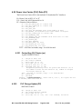
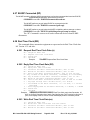
4.7 Output Change Update (CC)
0ACCZZZS00CC
0A – Length as ASCII hex
CC – Zone Change Message Command
ZZZ – Output Number, 1 based
S – Output State, 0 = OFF, 1 = ON
00 – future use
CC – Checksum
Example: 0ACC003100E5
Output change – Output 3, changed to ON
This transmission update option transmits the updated status
whenever it changes and is enabled by setting the location TRUE in
the M1 Control Global Programming Locations 37. Example: “Xmit
OutputChgs–ASCII” (Yes or No)
M1 Control RS-232 ASCII String Protocol
Page 20 of 68
Rev. 1.79 July 16, 2009
The Output Change Update will also be transmitted out M1XSP Serial Port
Expanders that are configured in the Generic Mode.
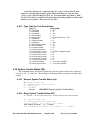
4.8 Audio Equipment Command (CD)
An M1XEP Ethernet Module is required to intercept the “cd” command. These
commands are sent into the M1XEP via the Ethernet connection and passed
through to the M1. The M1XEP builds custom audio commands to control the
audio equipment and sends these commands to the audio equipment via ethernet.
An IP232 Ethernet Module may be required at the audio equipment to received the
commands if no Ethernet Port is available on the audio equipment. The incoming
“cd” command can trigger Rules in the M1 which can fire outgoing audio
equipment “CD” commands or other control Rules. ELKRP downloads the Audio
Equipment Command tables into the M1XEP according to the Audio Equipment
Manufacturer. M1 version 4.1.11, 5.1.11 or later is required.
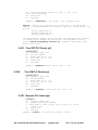
4.8.1 Incoming Audio Command (cd)
0F – Length as ASCII hex
cd – Request Audio Command
NN – Which audio command from Audio Command Table.
SS – Audio Source Information
ZZ – Audio Zone Information
VVV – Audio State or Value
00 – future use
CC – Checksum
The “cd” command may or may not use the audio source
and zone information.
Example: 0Fcd01020300000AD Audio command 1, Source 2, Zone 3, Power
On
Example: 0Fcd10020305000A8
Audio command 10, Source 2, Zone 3,
Volume Level = 50
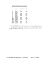
4.8.2 Audio Command Table (used by M1XEP)
Function
Power Off
Power On
Power Toggle On/Off
Next Source
Source
Previous Select
Next Select
Volume Down
Volume Up
Mute Audio
Volume set
M1 Control RS-232 ASCII String Protocol
Description (numeric NN value)
0-Turns the zone power Off.
1-Turns the zone power On.
2-Toggles Power state of a zone.
3-Steps to next source
4-Select a source input.
5-Steps backward to previous available.
6-Advances forward, next.
7-Decrement the zone volume.
8-Increment the zone volume.
9-Toggles the mute on/off of a zone.
10-Set zone volume to a level.
Page 21 of 68
Rev. 1.79 July 16, 2009
Play
Pause
Stop
Select Favorite #1
Select Favorite #2
Minus
Plus
All Zones Off
All Zones On
Audio System Manufacturer
11-Starts source Play
12-Pauses Play
13-Stop Play
14-Executes Favorite Playlist 1.
15-Executes Favorite Playlist 2.
16-Down Select
17-Up Select
18-Turn all zones off
19-Turn all zones on
20-Version number,
VVV value: 0 = No audio configured
1 = Russound
2 = Nuvo
3 = Proficient
99 = IP Failure
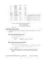
4.8.3 Outgoing Audio Command (CD)
Example:
Example:
0F – Length as ASCII hex
CD – Request Audio Command
NN – Which audio command from Audio Command
Table.
SS – Audio Source Information
ZZ – Audio Zone Information
VVV – Audio State or Value
00 – future use
CC – Checksum
0FCD02030400000EA Audio command 2, Source 3, Zone 4, Toggle
Power.
0FCD09030400000E3
Audio command 09, Source 3, Zone 4, Toggle
Mute.
4.9 Control Output Messages
You can use a PC to send a command to control a control panel output. The data
portion of the output on and off commands, DDD is a 3-digit, (1 base) referenced
decimal number corresponding to the number of the desired output, 1 to 208.
TTTTT is the number of seconds the output will be active. A value of 0 will stay
on until commanded to turn off. Range: 0 to 65535
You can also query the control panel concerning output status with a Control
Output Status Request. The control panel will respond with a Control Output Status
Report.
M1 Control RS-232 ASCII String Protocol
Page 22 of 68
Rev. 1.79 July 16, 2009
4.9.1 Control Output off (cf)
09cfDDD00CC(CR-LF)
Example: turn off Control Output 2: 09cf00200DC(CR-LF )
4.9.2 Control Output On (cn)
0EcnDDDTTTTT00CC(CR-LF)
Example: turn on Control Output 1 for 10 seconds: 0Ecn0010001000D8(CR-LF )
4.9.3 Control Output Status Request (cs)
06cs0064(CR-LF)
The control panel responds with a Control Output Status Report for all 208 outputs.
4.9.4 Control Output Status Report (CS)
D6CSD…00CC(CR-LF)
The control panel sends this message in response to a Control Output Status
Request. The data portion of this message is 208 characters long, one character for
each output in order. The value will be: 0 (Off), 1 (On).
Example: With control output 1 off, output 2 on, output 3 and output 4 off, the
message would begin D6CS0100…
4.9.5 Control Output toggle (ct)
09ctDDD00CC(CR-LF)
Example: toggle Control Output 2: 09ct00200CE(CR-LF )
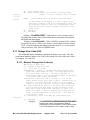
4.10 Change And Read Custom Values (CR)
This request command allows automation equipment to read and change a
Custom Value stored in the M1. Custom Values are user changeable values stored in
EEProm Memory such as sprinkler watering times or wakeup times.
4.10.1
digits, 1
20.
Read Custom Value (cr)
08 – Length as ASCII hex
cr – Read custom value
NN – Which Custom Value to be returned (2 decimal ASCII
based). ie.”16” = custom value 16. Range 1 to
00 – future use
CC – Checksum
Example: 08cr010002 Read custom value 1.
M1 Control RS-232 ASCII String Protocol
Page 23 of 68
Rev. 1.79 July 16, 2009
4.10.2
Read ALL Custom Values (cp)
06 – Length as ASCII hex
cp – Read ALL custom values
00 – future use
CC – Checksum
Example: 06cp0067 Read all custom values.
4.10.3
Reply With Custom Value (CR)
0E – Length as ASCII hex
Length fixed in M1 Version
4.3.1 and later
CR – Returned custom value
NN – Which Custom Value to be returned (2 decimal ASCII
digits, 1
based). ie.”16” = custom value 16. Range 1 to
20.
DDDDD – 16 bit Custom Value returned ( 5 decimal ASCII
digits)
If Format = 2, Time of day, this value should be
converted to a hexidecimal value. The low two bytes
will display the minutes in hexidecimal, the third
and fourth bytes will display the hours in
hexidecimal.
F - Custom value format. 0=Number, 1=Timer, 2=Time of day
00 – future use
CC – Checksum
Example: 0ECR01001230000F Returned value = 123, Number format, from Custom
Value 1
Example: 0ECR010541620003 Convert 5416 to hex = 15 28. Convert 15 to decimal
= 21. Convert 28 to hex = 40. Therefore time = 21:40 or 9:40 PM.
4.10.4
Reply With ALL Custom Values (CR)
80 – Length as ASCII hex
Length fixed in M1 Version
4.3.6 and later
CR – Returned custom value
NN = 00.
00 implies all 20 Custom Values returned.
DDDDD… – 16 bit Custom Value returned ( 5 decimal ASCII
digits)
If Format = 2, Time of day, this value should be
converted to a hexidecimal value. The low two bytes
will display the minutes in hexidecimal, the third
and fourth bytes will display the hours in
hexidecimal.
F - Custom value format. 0=Number, 1=Timer, 2=Time of day
… DDDDD and F above is repeated 19 more times
corresponding to each of the 20 custom values.
00 – future use
CC – Checksum
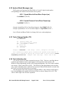
4.10.5
Write Custom Value (cw)
0D – Length as ASCII hex
M1 Control RS-232 ASCII String Protocol
Page 24 of 68
Rev. 1.79 July 16, 2009
digits, 1
1 to 20.
digits)
cw – write custom value
NN – Which Custom Value to be written (2 decimal ASCII
based). ie.”16” = custom value 16. Range
DDDDD – 16 bit Custom Value to write ( 5 decimal ASCII
If the Custom Value Format
the hours in bytes 3 and 4
the minutes in bytes 1 and
Then convert that value to
DDDDD value.
00 – future use
CC – Checksum
= 2, Time of day, place
as a hexidecimal value and
2 as a hexidecimal value.
decimal and place in the
Example: 0Dcw050012300F7 Written value = 123 into Custom Value 5.
The “Reply With Custom Value” (CR command above) string will be returned after
the EEprom has been written.
Example: 0Dcw010541600F1 Write 9:40 PM to Custom Value 1 which
was previously set as a Time of day format. Convert time to 24 hour format:
21:40. Convert the hours and minutes to hexidecimal 15 28. Convert entire
value to decimal: 5416. Place in DDDDD value.
4.11 Change User Code (CU)
This command allows automation equipment to change a user code. The data
packet must include a Master User Code or the current user code of the user code to
be changed. 4.3.9 and after.
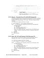
4.11.1 Request Change User Code (cu)
set/clear.
23– Length as ASCII hex
cu – Request change user code
ccc – User code to change
abababababab – Master or current user authorization code.
Upper and lower nibble of code. For user code the “a”
will be an ASCII zero (0). For Prox codes the “a”
expressed in ASCII, will be the upper nibble of the byte
of the Prox code. Right justified.
anananananan – New user code to change to. “a” is the
upper nibble of the user code in ASCII. Normally set to
zero(0). If a Prox code the value will be the upper
nibble of the Prox code byte in ASCII. Right justified.
NN – Areas code may be used in. Two ASCII Hex characters,
0-9,A-F, using the Hex value of each character as the
mask for 4 areas. Right most character is areas 1 to 4
with bit 0 equal to Area 1. Authorization code must be
valid in areas requested. If Area value = “00” then no
area change is made.
00 – future use, first byte used for Code Restriction
CC – Checksum
Example:
23cu0050000030405060000090807062100BB
Request user code 5 to be changed to 009876,
authorized by user code 003456. Code is valid in Areas
1 and 6 if authorization code is valid in Areas 1 and 6.
M1 Control RS-232 ASCII String Protocol
Page 25 of 68
Rev. 1.79 July 16, 2009
4.11.2 Reply Change User Code (CU)
0B – Length as ASCII hex
CU – Reply Lighting Device Status data
ccc – 000 = User code change denied due to invalid
authorization code, 001 to 254 indicates user code
that was changed. 255 = new code is a duplicate and
change is denied.
00 – future use
CC – Checksum
09CU005000A User code 005 was changed.
Example:
Example:
09CU000000F User code denied due to invalid
authorization code.
09CU2550003 User code denied due to duplicate
Example:
code.
Note: Setting the first future use byte to “1” in the “cu” command will set the user code
restriction which will prevent the code from being used. Setting the first future use byte to
“0”, enables the code to be used.
To M1: 23cu0050000030405060000080807062110BB
If you send the first Future
Use byte as a ‘1’, the code will not be programmed, but the restriction on the code will
be enabled.
From M1: 09CU0051009 Response from the M1 that the code is restricted.
To M1: 23cu0050000030405060000080807062120BA Sending a ‘2’ value in the first
Future Use byte takes the code restriction away.
From M1: 09CU005000A Response from M1 with the code restriction cleared.
4.12 Change And Read Counter Values (CV)
This request command allows automation equipment to read and change a
Counter Value stored in the M1. Counter Values are RAM based and may be used as
flags or to hold simple math values. This feature is available in M1 versions 4.1.11,
5.1.6 and later.
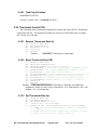
4.12.1 Read Counter Value (cv)
digits, 1
64.
08 – Length as ASCII hex
cv – Read counter value command
NN – Which Counter Value to be returned (2 decimal ASCII
based). ie.”16” = counter value 16. Range 1 to
00 – future use
CC – Checksum
Example: 08cv0100FE Read counter number 1.
4.12.2 Write Counter Value (cx)
0D – Length as ASCII hex
cx – Write counter value command
M1 Control RS-232 ASCII String Protocol
Page 26 of 68
Rev. 1.79 July 16, 2009
digits, 1
64.
NN – Which Counter Value to be returned (2 decimal ASCII
based). ie.”16” = counter value 16. Range 1 to
DDDDD – 16 bit Counter Value returned (Five decimal ASCII
digits). Range 0 to 65535.
00 – future use
CC – Checksum
Example: 0Dcx011234500F1 Write counter number 1 to a value of 12345.
Returns “CV” command string as reply.
4.12.3 Reply With Counter Value Format (CV)
digits, 1
64.
0D – Length as ASCII hex
CV – Returned Counter value command
NN – Which Counter Value to be returned (2 decimal ASCII
based). ie.”16” = counter value 16. Range 1 to
DDDDD – 16 bit Counter Value returned (Five decimal ASCII
digits)
Range 0 to 65535.
00 – future use
CC – Checksum
Example: 0DCV0100123003C Returned value = 123, from Counter
number 1
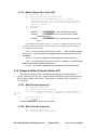
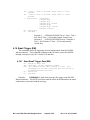
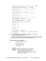
4.13 Display Text On LCD Screen (dm)
This is a M1 received message to display ascii text on the bottom line of the LCD
display on the keypads in the area specified. Enter the line terminator, “^”, as the
ending character of the line display if less than 16 characters are to be displayed. The
message line, L1 or L2, will need dummy characters to fill the rest of the line for 16
characters each line.
2E - Length as ASCII hex
dm - Display Message On Keypad Command
A - Keypad Area, 1 to 8
C - Clear, 0=clear message, 1=clear message with * key,
2=Display until timeout
B - Beep Keypad, 0=no beep, 1=beep
TTTTT - Display time in decimal seconds, 0=No timeout, 1 - 65535
seconds
L1[16] - 16 ASCII characters for first line
L2[16] - 16 ASCII characters for second line, alternately
scrolled with first line
00 - future use
CC - Checksum
Example: 2Edm11100020abc^efghijklmnopABCDEF^HIJKLMNOP00B2
Would display “abc” on the first line and “ABCDEF” on the second line
M1 Control RS-232 ASCII String Protocol
Page 27 of 68
Rev. 1.79 July 16, 2009
If the second line is not needed, enter a “^”as the first character of the second line.
The second line will be scrolled with the first line if it is included.
LCD will display:
Ready To Arm
abc
then
Ready To Arm
ABCDEF
4.14 Lighting Device Status Poll (DS)
This command allows the M1 to poll single light devices to obtain their
on, off, dim status. This will be an automatic command issued from the M1 to the
M1XSP Type modules that connect to lighting devices. Note: Only single light
devices can be polled for status. Groups and scenes will not return valid data. Enable
the “2 Way” Poll setting for the device to be polled. M1 Version 4.3.9 and after. This
command cannot be used by automation equipment.
4.14.1 Request Lighting Device Status (ds)
= 001
09 – Length as ASCII hex
ds – Request lighting device status
aaa – Lighting device number 001 to 256, base 1, device A1
00 – future use
CC – Checksum
Example:
09ds00100CF Request lighting device status of
lighting device 001.
4.14.2 Reply Lighting Device Status Data (DS)
0B – Length as ASCII hex
DS – Reply Lighting Device Status data
aaa – Lighting device number 001 to 256, base 1, device A1
= 001
level
ss – Lighting status. 00 = Off, 01 = Full On, 2 to 99 = Dim
00 – future use
CC – Checksum
0BDS001990094
Example:
001, set to a dim level of 99%.
Reply lighting status of device
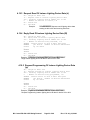
4.15 Entry/Exit Time Data (EE)
This sends the entry 1 & 2 and exit 1 & 2 time data when the timers start by area.
When each exit timer expires an “EE” command is also transmitted. M1 Version
4.1.12, 5.1.12 or later. Armed State available in 4.1.18, 5.1.18 or later.
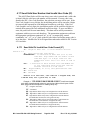
4.15.1 Send Entry/Exit Data (EE)
0F – Length as ASCII hex
EE – Send exit/entry timer data.
A – Area, “1” to “8”.
D – Data Type. “0” = Exit, “1” = Entrance time.
M1 Control RS-232 ASCII String Protocol
Page 28 of 68
Rev. 1.79 July 16, 2009
ttt – Timer 1 value in seconds. Range “000” to “255”
seconds.
TTT – Timer 2 value in seconds. Range “000” to “255”
seconds.
S – Armed State
0=Disarmed
1=Armed Away
2=Armed Stay
3=Armed Stay Instant
4=Armed Night
5=Armed Night Instant
6=Armed Vacation
00 – future use
CC – Checksum
Example 1: 0FEE10060120100E5Area 1, Exit 1 Time =
060, Exit 2 Time = 120 seconds started, Armed Away.
Example 2: 0FEE21030254200DD Area 2, Entrance 1
Time = 030, Entrance 2 Time = 254 seconds started,
Armed Stay.
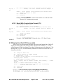
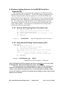
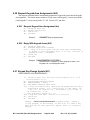
4.16 Email Trigger (EM)
This command allows the triggering of email transmissions from the M1XEP
Ethernet interface. This command originates in the M1 and is sent to the M1XEP
through serial port 0 only. M1 Version 4.2.8 and after.
4.16.1 Send Email Trigger Data (EM)
09 – Length as ASCII hex
EM – Send email trigger command to M1XEP.
DDD – The address of the email message to send. This
corresponds to the email messages that are stored in
the M1XEP Ethernet interface.
00 – future use
CC – Checksum
Example:
09EM0010014 Send email message 001 trigger to the M1XEP
Ethernet interface. The M1XEP will then send the email on the Ethernet to the email
address that is associated with the message.
M1 Control RS-232 ASCII String Protocol
Page 29 of 68
Rev. 1.79 July 16, 2009
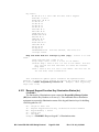
4.17 Send Valid User Number And Invalid User Code (IC)
This ASCII Data Packet will be sent when a user code is entered and a valid code
is found. Only the valid user code number will be returned. If a user code is not
found in the M1’s User Code Data Base, the code that was enter will be sent. If the
User Code Length is set to 4 digits, the invalid data packet will be sent after 4 digits
are entered, then repeated for each additional invalid user code digit. If the User
Code Length is set to 6 digits, the invalid data packet will be sent after 6 digits are
entered, then repeated for each additional invalid user digit. If prox card data is
enter, the packet will be sent immediately. This data can be used by automation
equipment with its own user code data base. The automation equipment would sent
the appropriate arm/disarm command (“a0” to “a6”) or output relay control
commands (“cn”, “cf”, or “ct”) back to the M1 after it has verified the proper code is
in its data base. Modified for 26 bit Weigand data cards and available in M1 Version
4.2.8 and after.
4.17.1 Send Valid Or Invalid User Code Format (IC)
17 – Length as ASCII hex. 12 in M1 software versions
before 4.3.2
IC – Send Invalid User Code digits
DDDDDDDDDDDD – 12 characters of ASCII Hex (0 to F) user
code data. High nibble and low nibble of each
code data byte. 4 & 6 digit codes are left
padded with zeros. Set to all zeros if code is
valid.
UUU - 3 characters of ASCII decimal User Code Number 001
to 103, indicating which valid user code was
entered. Version 4.3.2 and later.
NN - Keypad number, 01 to 16, that generated the code.
00 – future use
CC – Checksum
Version 4.4.2 and later, user code 201 = Program Code, 202
= ELK RP Code, 203 = Quick Arm, no code.
Example 1: 17IC 00 00 03 04 05 06 000 01 00CC Invalid user keypad
code 3456. Keypad entered codes only use the low nibble of the 6 bytes of code
data. Spaces in this example are for reading clarity only.
17 – Length as ASCII hex
IC – Command
00 – high and low nibble of byte one in high and low ASCII character.
00 – high and low nibble of byte two in high and low ASCII character.
03 – high and low nibble of byte three in high and low ASCII character.
Low nibble has first character of keypad code entry.
04 – high and low nibble of byte four in high and low ASCII character.
Low nibble has second character of keypad code entry.
05 – high and low nibble of byte five in high and low ASCII character.
Low nibble has third character of keypad code entry.
06 – high and low nibble of byte six in high and low ASCII character.
M1 Control RS-232 ASCII String Protocol
Page 30 of 68
Rev. 1.79 July 16, 2009
Low nibble has fourth character of keypad code entry.
000 – Valid user code number. Set to 0 for an invalid user code.
01 - Keypad number 01 generated the code.
00 - Future Use
CC – Checksum
Example 2: 17IC 123456789012 000 01 004B Invalid 26 bit Weigand
prox card code. Prox card codes use the high and low nibbles of the 6 bytes of
code data. Spaces in this example are for reading clarity only.
17IC – length and command
123456789012 - Example prox card code. ASCII Hex (0 to F).
000 – Valid user code number. Set to 0 for an invalid user code.
01 – Keypad number that generated code.
004B - not used byte characters and checksum
Example 3: 17IC 000000000000 003 01 0078 Valid user code. Prox
card codes use the high and low nibbles of the 6 bytes of code data. Spaces in
this example are for reading clarity only.
17IC – length and command
000000000000 – Invalid user code data is set to all zeros on a valid user
code. This hides all valid codes.
003 – Valid user code number 3.
01 – Keypad number that generated code.
0078 - not used byte characters and checksum
4.18 Installer Program Mode Exited (IE)
This command is automatically sent through serial port 0 only when the installer
mode is terminated. This is done by pressing the “*” key three times or the installer
timer runs out. This command is used by the M1XEP Ethernet Interface to know
when to reload M1 program data after an installer has done any keypad programming.
M1 Version 4.2.8 and after.
4.18.1 Send Installer Mode Exited (IE)
06
IE
00
CC
–
–
–
–
Length as ASCII hex
Send installer mode exited.
future use
Checksum
Example:
06IE00AC Send installer mode has exited.
The “IE” is sent out when ELK RP disconnects. See section 4.33 ELKRP
Connected (RP) for additional information.
M1 Control RS-232 ASCII String Protocol
Page 31 of 68
Rev. 1.79 July 16, 2009
4.19 Insteon Lighting Systems for the M1XSP Serial Port
Expander (IR)
This command allows programming and reading from the M1XSP Serial Port
Expander the Insteon device addresses. The M1XSP’s jumper configuration is set
for Insteon Operation and the alternate application code in the M1XSP has been
loaded with the Insteon Application. Commands may be sent to program and read
the Insteon device IDs. Lighting device descriptions may also be accessed from the
M1. The connecting PC’s baud rate must be set for 4800 baud, 8 bits, no parity.
Connection is through the 9 Pin, RS-232 connector on the M1XSP module with a
NULL Modem adapter. All data packets are terminated with a carriage return
(0x0D) with a line feed option (0x0A).
4.19.1 Request ASCII Lighting Device Description (sd)
0B – Length as ASCII hex
sd – Request ASCII String Text Descriptions Command
07 – Lighting device description
NNN – Which lighting description to be returned, 1 – 192
00 – future use
CC – Checksum
Example:
0Bsd07001005F
Request Lighting Device 001 (A1) Name.
4.19.2 Reply With ASCII String Text Descriptions (SD)
Reply format:
1B – Length as ASCII hex
SD – Reply ASCII Lighting Device Command
07 – Lighting device description
NNN – Which lighting device description being returned,
001 – 192
Text[16] – 16 ASCII characters, “space” character
(20 hex) filled if less than 16 characters.
00 – future use
CC – Checksum
Example: 1DSD07001Hall Light 0089D2
Lighting Device 001 Description – “Hall Light”
Note: The high bit of the first character in the text string may be set as the “Show
On Keypad” bit. Mask out the high bit for proper ASCII display.
If the first character in a requested name is a “space” or less, then the next
names are searched until a name is found whose first character is greater than
“space” or the “Show On Keypad” bit is set. If no valid names are found, a “000”
for the NNN address is returned. This speeds up the loading of names so that invalid
names are not returned.
M1 Control RS-232 ASCII String Protocol
Page 32 of 68
Rev. 1.79 July 16, 2009
4.19.3 Request Read Of Insteon Lighting Device Data (ir)
0A – Length as ASCII hex
ir – Request read of Insteon lighting device data
aaa – Starting Lighting device number 001 to 192
n
- Number of devices to return, 1-8
00 – future use
CC – Checksum
0Air0018008B Request read of lighting device data
Example:
starting at device 001 and returning 8 devices.
4.19.4 Reply Read Of Insteon Lighting Device Data (IR)
XX – Length as ASCII hex
IR – Reply read of Insteon lighting device data
aaa – Starting Lighting device number 001 to 192
n
- Number of devices being returned, 1-8
AAAAAA Insteon Device ID with 6 ASCII Hex bytes
BBBBBB
per device. Number of devices determined
CCCCCC
by “n” above
…
EEEEEE
FFFFFF
00 – future use
CC – Checksum
Example: 22IR0014123456ABCDEF987654A1B2C3006F
Reply Insteon lighting device ID data for device 001 to 004.
4.19.5 Request Programming Of Insteon Lighting Device Data
(ip)
XX – Length as ASCII hex
ip – Request Program of Insteon lighting device data
aaa – Starting Lighting device number 001 to 192
n
- Number of devices being programmed, 1-8
AAAAAA Insteon Device ID with 6 ASCII Hex bytes
BBBBBB
per device. Number of devices determined
CCCCCC
by “n” above
…
EEEEEE
FFFFFF
00 – future use
CC – Checksum
Example: 22ip0014123456ABCDEF987654A1B2C30031
Request Programming Insteon lighting device ID data for device 001 to 004.
M1 Control RS-232 ASCII String Protocol
Page 33 of 68
Rev. 1.79 July 16, 2009
4.20 Request Keypad Area Assignments (KA)
This request command allows automation equipment to request the Areas that all keypads
are assigned to. The return string contains a 16 byte array with keypad 1’s area at array index
0 and keypad 15’s area in array index 15. M1 Version 4.2.5 and after.
4.20.1 Request Keypad Area Assignment (ka)
06
ka
00
6E
–
–
–
–
Length as ASCII hex
Request keypad areas
future use
Checksum
Example:
06ka006E Request keypad areas.
4.20.2 Reply With Keypad Areas (KA)
16 – Length as ASCII hex
KA – Returned Keypad Areas Command
D[16] – array of 16 ascii bytes with the first byte corresponding
to keypad 1’s area assignment (area ‘1’ to ‘8’), last byte is
keypad 16’s area assignment.
00 – future use
CC – Checksum
Example: 16KA12345678111111110081
Returned value = keypads 1 to 8 are assigned to areas 1 to 8.
Keypads 9 to 16 are assigned to area 1.
4.21 Keypad KeyChange Update (KC)
19KCNNDDLLLLLLCPPPPPPPP00CC
19 – Length as ASCII hex, (0A in M1 revision before 4.2.8, 11 in
revision before 4.3.2)
KC – Keypad Change Message Command
NN – Keypad Number, 1 based
DD – Key Number from Key Table Below
L[6] – Array of 6 ASCII bytes, indicating the Keypad Function Key’s
illumination status. L[0] = Function Key 1’s LED status. “0”
= Off, “1” = On constant, “2” = On Blinking. L[5]= F6 LED. In
M1 software rev. 4.2.8.
C – Code required to bypass if = “1”
P[8] – Beep and chime mode. Version 4.3.2 and after
00 – future use
CC – Checksum
Example: 19KC01112010000200000000010 Keypad change – Keypad 1,
“*” Key pressed, F1 LED blinking, F3 LED is On, all other F Key
LED’s are Off, No code required to bypass, Area 1 is constantly
beeping.
M1 Control RS-232 ASCII String Protocol
Page 34 of 68
Rev. 1.79 July 16, 2009
Key Table:
NO KEY = 0 or a user code was sent from a keypad.
STAR KEY (*) = 11
POUND KEY (#) = 12
F1 KEY = 13
F2 KEY = 14
F3 KEY = 15
F4 KEY = 16
STAY KEY = 17
EXIT KEY = 18
CHIME KEY = 19
BYPASS KEY = 20
ELK KEY = 21
DOWN KEY = 22
UP KEY = 23
RIGHT KEY = 24
LEFT KEY = 25
F6 Key = 26
F5 Key = 27
DATAKEYMODE = 28 Data was entered, this acts as a
carriage return
Beep and Chime mode bit settings by area (P[8]): Version 4.3.2 and
after.
Chime and beep OFF = 0x30 or ‘0’
Single beep = 0x31 or bit 0 is set in low nibble.
Constant beep = 0x32 or bit 1 is set in low nibble. This bit
will only be set once and reset to 0 when the constant
beep ends.
Chime = 0x34 or bit 4 is set in low nibble. This bit will be
set and reset after transmission.
This transmission update option transmits the updated status
whenever it changes and is enabled by setting the location TRUE in the
M1 Control Global Programming Location 40. Example: “Xmit Keypad Key
Chgs” (Yes or No)
4.21.1 Request Keypad Function Key Illumination Status (kc)
08kc010009
The function key illumination request returns the Keypad KeyChange Update
(KC) data with the Key Number set to zero (0). This command allows automation
equipment to request the illumination status of the keypad function keys for building
virtual keypads on a PC.
08 – Length as ASCII hex
kc – Request Keypad Function Key Illumination Status Command
NN – Keypad Number, 1 based
00 – future use
CC – Checksum
Example: 08kc010009 Request keypad 1’s illumination status.
M1 Control RS-232 ASCII String Protocol
Page 35 of 68
Rev. 1.79 July 16, 2009
Returns: 11KC01001000000009E Keypad 1’s Function Key F1 is illuminated as
described in “KC” command above.
4.22 Keypad Function Key Press (KF)
This command simulates a function key being pressed on a keypad. This will only be
single key press even if the M1 Control is programmed for double function key press. M1
Version 4.2.5 and after. ‘*’ key M1 Version 4.2.6 and after, ‘C’ key M1 Version 4.3.2 and
after.
4.22.1 Request Keypad Function Key Press (kf)
09
kf
NN
D
–
–
–
-
Length as ASCII hex
Function key pressed
Keypad 01 to 16
Which function key pressed, 1 to 6 ASCII, ‘*’ = 0x2A to
silence trouble beep on keypads. ‘C’ = 0x43 to control Chime,
‘0’ function key value will only return the “KF” command
00 – future use
CC – Checksum
Example:
09kf01100D4 Keypad 01, Function Key 1 to be pressed
4.22.2 Reply Keypad Function Key Press (KF)
11
KF
NN
D
–
–
–
-
Length as ASCII hex
Function key pressed
Keypad 01 to 16
Which function key pressed, 1 to 6 ASCII, ‘*’ = 0x2A, ‘C’ =
Chime.
CM[8] – Chime mode for each area 1 to 8, ‘0’= Off, ‘1’=Chime only,
‘2’ = Voice only, ‘3’= Chime and voice.
00 – future use
CC – Checksum
Example: 11KF01C200000000087 Function key reply with Chime Mode set
to voice only in Area 1.
M1 Control RS-232 ASCII String Protocol
Page 36 of 68
Rev. 1.79 July 16, 2009
4.23 System Log Data Update (LD)
As the control log is written, the same information is sent out the RS-232 port. The log
information will have the ddd index value set to “000” to indicate a logging entry.
The log data may also be requested with the “ld” (lower case “LD”) command below.
Modified in M1 version 4.3.2
1CLDEEEENNNAHHMMmmDDdddDYY00CC
1C – Length as ASCII hex
LD – Log Data Message Command
EEEE – Event
NNN – Event Number Data, i.e. Zone number, user number, etc.
A – Area Number 1 – 8
HH – Hour
MM – Minute
mm – Month
DD – Day
ddd – Decimal index to which log data, 001 to 511, added in M1
version 4.3.2
D – Day of week, ‘1’ = Sunday, ‘7’ = Saturday
YY – Year as “05” = 2005
00 – future use
CC – Checksum
Example: 1CLD1193102119450607001505003F AnyArmed event-1193, user 102,
Area 1, at 19:45 on June 07, Log index 001, Thursday, 2005
The “System Log Data Update” transmission option, transmits the updated status whenever
it changes and is enabled by setting the location TRUE in the M1 Control Global
Programming Locations 35. Example: “Xmit Event Log–ASCII” (Yes or No). The request for
log data “ld” is not controlled by this option.
4.23.1 Request System Log Data (ld)
Request to get system log data entry. The first entry is index “1”, the last entry is index
“511”. Log data index “0” is the next location to be written, index 511 is the oldest log data.
09 – Length as ASCII hex
ld – Request Log Data entry command (lower case ‘LD’)
ddd – Decimal index to which log data
00 – future use
CC – Checksum
Example:
09ld00100D6 Request log data for index 1, the newest log data.
Replies with the “LD” log data command above.
M1 Control RS-232 ASCII String Protocol
Page 37 of 68
Rev. 1.79 July 16, 2009
4.23.2 Request Write Log Data (le)
The Write Log Data Command “le” writes log data into the M1 log specifically to trigger
communicator reporting to the central station. A valid zone must be programmed for
communicator reporting. The M1 will return an “OK”crlf response when the data is written to
the log.
10 – Length as ASCII hex
le – Request Log Data entry write command (lower case ‘LE’)
LLL = Log Type,
Alarm = 128, Alarm Restore = 064
EEE = Event Type, 001 to 386, drop the thousand character from
Event Table 7.0 below.
ZZZ = Zone Number, 001 to 999
A = Area,
1 to 8
00 – future use
CC – Checksum
4.24 Zone Temperature And Keypad Temperature (LW)
This command allows automation equipment to request the temperatures from zone
temperature sensors and keypad temperatures in one ASCII packet. M1 Version 4.3.4 and
after.
4.24.1 Request Temperature Data (lw)
06
lw
00
CC
–
–
–
–
Length as ASCII hex
Request real temperature data
future use
Checksum
06lw0057 Request keypad and zone sensor temperature Data.
Example:
“lw” is lower case “LW”
4.24.2 Reply Temperature Data (LW)
66 – Length as ASCII hex
LW – Reply Temperature data
aaa – Keypad 1 temperature, as 3 ASCII characters, subtract 40.
bbb – Keypad 2 temperature, as 3 ASCII characters, subtract 40.
… 13 – 3 ASCII characters for each keypad, 3 to 15
ppp – Keypad 16 temperature, as 3 ASCII characters, subtract 40.
AAA – Zone Sensor 1 temperature, as 3 ASCII char., subtract 60.
BBB – Zone Sensor 2 temperature, as 3 ASCII characters, sub 60.
… 13 – 3 ASCII characters for each Zone Sensor, 3 to 15
PPP – Zone Sensor 16 temperature, as 3 ASCII characters, sub 60.
00 – future use
CC – Checksum
Example:
66LW108109000…000130000007A Keypad 1 temperature is 68
degrees F. (108 – 40). Keypad 2 temperature is 69 degrees F. (109 – 40). Zone 15
temperature sensor is 70 degrees F. (130 – 60).
M1 Control RS-232 ASCII String Protocol
Page 38 of 68
Rev. 1.79 July 16, 2009
4.25 Power Line Carrier (PLC) Data (PC)
The Power Line Carrier (PLC) data includes X-10 and other PLC interfaces.
H = House Code, ASCII “A” to “P”
UU = Unit Code, ASCII decimal 01 to 16
FF = Function Code as follows:
01
02
03
04
05
06
07
08
09
10
11
12
13
14
15
=
=
=
=
=
=
=
=
=
=
=
=
=
=
=
X10_ALL_UNITS_OFF in a House code
X10_ALL_LIGHTS_ON in a House code
X10_UNIT_ON
X10_UNIT_OFF
X10_DIM, EE extended value holds number of dims
X10_BRIGHT, EE extended value holds number of brights
X10_ALL_LIGHTS_OFF in a House code
X10_EXTENDED_CODE
X10_PRESET_DIM, EE extended value hold level 0 to 99%
X10_EXTENDED_DATA
X10_STATUS_REQ
X10_HAIL_REQUEST
X10_HAIL_ACK, not used
X10_STATUS_ON, not used
X10_STATUS_OFF, not used
TTTT = ON Time in seconds, range - 0 to 9999 decimal
4.25.1 Control Any PLC Device (pc)
11pcHUUFFEETTTT00CC
11
pc
H
UU
FF
EE
Length as ASCII hex
PLC Control Command
House Code ‘A’ to ‘P’
Unit Code ‘01’ to ‘16’
Function Code ‘01’ to ‘16’
Extended Code ‘00’ to ‘99’
Brightness percentage level for preset dim function (9) or
the number of dims for dim function (5), number of brights
for bright function (6).
TTTT – ON Time in seconds, range - 0 to 9999 decimal
00 – future use
CC – Checksum
Example: 11pcA01010000050043 House Code A, Unit 1, All Lights Off for
5 seconds, then turn back On.
4.25.2
–
–
–
–
–
PLC Change Update (PC)
0BPCHUULL00CC
0B
PC
H
UU
–
–
–
Length as ASCII hex
PLC Change Message Command
House Code ‘A’ to ‘P’
Unit Code ‘01’ to ‘16’, ‘00’ = All Command, see below.
M1 Control RS-232 ASCII String Protocol
Page 39 of 68
Rev. 1.79 July 16, 2009
LL – Level/scene/state Status, 0 = OFF, 1 = ON, 2-99 =
light level percentage
00 – future use
CC – Checksum
Example: 0BPCA01000099
PLC change – A01, changed to OFF
Special: When an All_Lights_On, All_Lights_OFF, or All_Units_Off
command is transmitted the Unit Code will equal 00, and the Level (LL)
will be:
X10_ALL_UNITS_OFF = 01
X10_ALL_LIGHTS_ON = 02
X10_ALL_LIGHTS_OFF = 07
This transmission update option transmits the updated status whenever
it changes and is enabled by setting the location TRUE in the M1
Control Global Programming Location 39. Example: “Xmit Light Chgs–
ASCII” (Yes or No)
4.25.3 Turn OFF PLC Device (pf)
09pfHUU00CC
09
pf
H
UU
00
CC
–
–
–
–
–
Length as ASCII hex
PLC OFF Command
House Code ‘A’ to ‘P’
Unit Code ‘01’ to ‘16’
future use
Checksum
Example: 09pfA0100BF House Code A, Unit 1, Off
4.25.4
Turn ON PLC Device (pn)
09pnHUU00CC
09
pn
H
UU
00
CC
–
–
–
–
–
Length as ASCII hex
PLC ON Command
House Code ‘A’ to ‘P’
Unit Code ‘01’ to ‘16’
future use
Checksum
Example: 09pnA0100B7
House Code “A”, Unit 1, On
4.25.5 Request PLC status (ps)
07psb00CC
07 – Length as ASCII hex
ps – request PLC status Command
b – Bank (ASCII), 0=A1 to D16, 1=E1 to H16, 2=I1 to L16,
3=M1 to P16
00 - future use
CC - Checksum
Example: 07ps00026 PLC status for bank A1 to D16
M1 Control RS-232 ASCII String Protocol
Page 40 of 68
Rev. 1.79 July 16, 2009
4.25.6 Returned PLC status (PS)
47PSBD… 00PCC
47 – Length as ASCII hex
PS – request PLC status Command
B - Bank, 0=A1 to D16, 1=E1 to H16, 2=I1 to L16, 3=M1 to P16
D - 64 bytes, current status of the PLC environment by bank 0 to 3.
Subtract 48 or 0x30 hex from the value in “D”. This will
give the light level value, (M1 version 4.2.6)
then 0 = OFF, 1 = ON, 2 – 99 = Dim Level.
00 – future use
CC – Checksum
Example:
47PS001111111111111110000000000000000000000000000000000000000000000000053
Bank 0 (A to D Housecodes) has A2 to A16 turned On.
4.25.7 Toggle PLC Device (pt)
09ptHUU00CC
09
pt
H
UU
00
CC
–
–
–
–
–
Length as ASCII hex
PLC toggle state Command
House Code ‘A’ to ‘P’
Unit Code ‘01’ to ‘16’
future use
Checksum
Example: 09ptA0100B1
House Code “A”, Unit 1, Toggle
4.26 Reset Ethernet Module (RE)
This command is originated from the M1 and causes the M1XEP Ethernet Module to reset
its processor and/or its IP address to: 192.168.0.251. This can be used when the IP address of
the M1XEP is set to an unknown value. This is accessed through the M1’s Keypad Global
Installer Programming, Option 45, then enter 96. M1 Version 4.3.7 and after.
07 – Length as ASCII hex
RE – Request Request Ethernet Reset
D – “0”= Reset the Ethernet Module, “1”= Reset the Ethernet IP
Address and Reset Module.
00 – future use
CC – Checksum
4.26.1 Reset Ethernet IP Address(RE)
07RE00072 Reset the Ethernet Module.
07RE10071 Reset the Ethernet Module and set the IP Address to 192.168.0.251.
M1 Control RS-232 ASCII String Protocol
Page 41 of 68
Rev. 1.79 July 16, 2009
4.27 ELKRP Connected (RP)
The M1XEP sends the following ASCII command out to all socket connected devices when ELK RP,
Upload/Download Software, disconnects from the M1:
08RP000036<cr><lf>. ELKRP disconnected broadcast.
The M1XEP replies to any poll when ELKRP is connected to the M1:
08RP010035<cr><lf>. ELKRP is connected, poll reply
The M1XEP replies to any poll when the M1XEP is initializing after a powerup or reboot:
08RP020034<cr><lf>. M1XEP is initializing after powerup or reboot.
The “IE” Command is sent out to all socket connected devices when ELKRP
disconnects.
4.28 Real Time Clock (RR)
This command allows automation equipment to request and write Real Time Clock data.
M1 Version 4.3.2 and after.
4.28.1 Request Real Time Clock Data (rr)
06
rr
00
CC
–
–
–
–
Length as ASCII hex
Request real time clock data
future use
Checksum
Example:
06rr0056 Request Real Time Clock Data.
4.28.2 Reply Real Time Clock Data (RR)
16 – Length as ASCII hex
RR – Reply real time clock data
ss – second as two ASCII characters decimal, “00” to “59”
mm – Minute as two ASCII characters decimal, “00” to “59”
hh – Hour as two ASCII characters decimal, “00” to “23” 24 hour
D – Day of week as one ASCII character, “1”=Sunday to “7”=Saturday
DM – Day of month as two ASCII characters decimal, “01” to “31”
MM – Month as two ASCII characters decimal, “01” to “12”
YY – Year as two ASCII characters decimal, “00” to “99” as in 2099
S - Daylight Savings Time: “0”=Not active, “1”= Active.
C - Clock Mode as one ASCII character, ‘1’ = 12 hour, 0 = 24 hour
time mode
T - Date Display Mode as one ASCII character, 0 = mm/dd, 1 = dd/mm
00 – future use
CC – Checksum
Example: 16RR0059107251205110006E Real Time Clock reply data: December 25,
2005, at 10:59:00, Saturday day of week, Day light Savings Time is active for this time of
year, Clock display mode is 12 hour format, Date display mode is month/day format.
4.28.3 Write Real Time Clock Data (rw)
13
rw
ss
mm
–
–
–
–
Length as ASCII hex
Write real time clock data into the Control
second as two ASCII characters decimal, “00” to “59”
Minute as two ASCII characters decimal, “00” to “59”
M1 Control RS-232 ASCII String Protocol
Page 42 of 68
Rev. 1.79 July 16, 2009
hh – Hour as two ASCII characters decimal, “00” to “23” 24 hour
D – Day of week as one ASCII character, “1”=Sunday to “7”=Saturday
DM – Day of month as two ASCII characters decimal, “01” to “31”
MM – Month as two ASCII characters decimal, “01” to “12”
YY – Year as two ASCII characters decimal, “00” to “99” as in 2099
00 – future use
CC – Checksum
Example: 13rw305923111050500C0 Set Real Time Clock to:
May 11, 2005 at 11:59:30 PM or 23:59:30 hours. Sunday day of week.
Acknowledge will be “RR” Real Time Clock data above.
4.29 ASCII String Text Descriptions (SD)
This request command allows automation equipment to read the text descriptions that are
stored in the control.
4.29.1 Request ASCII String Text Descriptions (sd)
0B – Length as ASCII hex
sd – Request ASCII String Text Descriptions Command
TT – Type of string text description to request. See Type
Table below.
NNN – Which name in the Type to be returned. ie.003=zone 3.
00 – future use
CC – Checksum
Example:
0Bsd010010065
Area Name-Type 1, Area 1
4.29.2 Reply With ASCII String Text Descriptions (SD)
Reply format:
1B – Length as ASCII hex
SD – Reply ASCII String Text Descriptions Command
TT – Type of string text description in reply.
See Type Table below
NNN – Which address name in the Type to be returned.
ie.003=zone 3.
Text[16] – 16 ASCII characters, “space” character
(20 hex) filled if less than 16 characters.
00 – future use
CC – Checksum
Example 1: 1BSD01001Front DoorKeypad0089
Area Name -Type 1, Area 1, “Front DoorKeypad”
Example 2: 1BSD05001Garage Door 0005
Task Name – Type 5, Task 1, “Garage Door”
Note: The high bit of the first character in the text string may be set as the
“Show On Keypad” bit. Mask out the high bit for proper ASCII display.
M1 Control RS-232 ASCII String Protocol
Page 43 of 68
Rev. 1.79 July 16, 2009
If the first character in a requested name is a “space” or less, then the next
names are searched until a name is found whose first character is greater than
“space” or the “Show On Keypad” bit is set. If no valid names are found, a “000”
for the NNN address is returned. This speeds up the loading of names so that invalid
names are not returned. M1 version 2.4.6 or later.
4.29.3 Type Table for Text Descriptions:
Type (TT)
0 = Zone Name
1 = Area Name
2 = User Name
3 = Keypad Name
4 = Output Name
5 = Task Name
6 = Telephone Name
7 = Light Name
8 = Alarm Duration Name
9 = Custom Settings
10 = Counters Names
11 = Thermostat Names
12 = Function Key 1 Name
13 = Function Key 2 Name
14 = Function Key 3 Name
15 = Function Key 4 Name
16 = Function Key 5 Name
17 = Function Key 6 Name
18 = Audio Zone Name
19 = Audio Source Name
Range (NNN)
1 – 208
1–8
1 – 199
1 – 16
1 – 64, No name for 65 – 208
1 – 32
1–8
1 – 256
1 – 12
1 – 20
1 – 64
1 – 16
1 – 16, NNN = Keypad number
1 - 16
1 - 16
1 - 16
1 - 16
1 – 16
1 – 18 for use by M1XEP
1 – 12 for use by M1XEP
4.30 System Trouble Status (SS)
This command allows automation equipment to poll for system trouble status. Firmware
revision 4.5.4, 5.1.4 and after. This message will automatically be sent upon a trouble status
change.
4.30.1 Request System Trouble Status (ss)
06– Length as ASCII hex
ss – Request System Trouble Status
00 – future use
CC – Checksum
06ss0054 Request System Trouble Status
Example:
4.30.2 Reply System Trouble Status (SS)
“0” = Normal, “1” or a hex value minus 30 hex = Trouble and/or the zone or device number.
28 – Length as ASCII hex
SS – Reply System Trouble Status data
AC Fail Trouble – “0” = normal, “1” = trouble
*Box Tamper Trouble – “0” = normal
Fail To Communicate Trouble – “0” = normal, “1” = trouble
M1 Control RS-232 ASCII String Protocol
Page 44 of 68
Rev. 1.79 July 16, 2009
EEProm Memory Error Trouble – “0” = normal, “1” = trouble
Low Battery Control Trouble – “0” = normal, “1” = trouble
*Transmitter Low Battery Trouble – “0” = normal
Over Current Trouble – “0” = normal, “1” = trouble
Telephone Fault Trouble – “0” = normal, “1” = trouble
Not Used = “0”
Output 2 Trouble – “0” = normal, “1” = trouble
Missing Keypad Trouble – “0” = normal
Zone Expander Trouble – “0” = normal, “1” = trouble
Output Expander – “0” = normal, “1” = trouble
Not Used = “0”
ELKRP Remote Access – “0” = normal
Not Used = “0”
Common Area Not Armed – “0” = normal, “1” = trouble
Flash Memory Error Trouble – “0” = normal, “1” = trouble
*Security Alert – “0” = normal
Serial Port Expander Trouble – “0” = normal
*Lost Transmitter Trouble – “0” = normal
GE Smoke CleanMe Trouble– “0” = normal
Ethernet Trouble – “0” = normal, “1” = trouble
Not Used = “0”
Not Used = “0”
Not Used = “0”
Not Used = “0”
Not Used = “0”
Not Used = “0”
Not Used = “0”
Not Used = “0”
Display Message In Keypad Line 1
Display Message In Keypad Line 2
*Fire Trouble – “0” = normal, ‘1’ or greater, see below.
00 – future use
CC – Checksum
Example: 28SS1000000000000000000000000000000000002F = AC Failure Trouble
Fire Trouble zone in the “SS” command:
Take the value displayed in the Fire Trouble location which is an ASCII ‘A’ in the example
below which equals a 65 decimal value and subtract 48 decimal from it. This equals 17 which
is the fire zone in trouble. Reference the ASCII Table in section 6.0 below.
* Determining the zone number for:
Transmitter Low Battery Trouble
Box Tamper Trouble
Security Alert Trouble
Lost Transmitter Trouble
Fire Trouble
06ss0054
28SS000000000100000000000000000000010A001D
Example:
ASCII ‘A’ = 65 decimal or 41 hex (0x41)
Subtract ASCII ‘0’ from the value.
That is: Subtract 48 decimal or 30 hex (0x30) ‘0’
65 – 48 = 17 or zone 17
M1 Control RS-232 ASCII String Protocol
Page 45 of 68
Rev. 1.79 July 16, 2009
4.31 Request Temperatures (ST)
This request command allows automation equipment to read temperatures of the
temperature probes connected to zones 1 to 16, Keypad temperature from the sensor in each
LCD keypad, and Thermostat temperatures. Each Group can have upto 16 temperature
sensors.
Version 4.2.8 and later sends automatic temperature updates out Port 0 when any
temperature device parameter changes.
4.31.1 Request Temperature format (st)
09 – Length as ASCII hex
st – Request Temperature Command
G - Requested Group (ASCII): “0”=temperature probe,
“1”=Keypads, “2”=Thermostats
NN – Which device in the group to be returned (2 decimal
ASCII digits, 1 based). ie.”16” = device 16
00 – future use
CC – Checksum
Example: 09st00100BF Temperature Probe, Device 01
Example: 09st10100BE Keypad Temperature, Device 01
Example: 09st20100BD Thermostat, Device 01
4.31.2 Reply With Requested Temperature (ST)
Reply format:
0C – Length as ASCII hex
ST – Reply Temperature Command
G - Requested Group (ASCII): “0”=temperature probe,
“1”=Keypads, “2”=Thermostats
NN – Which device in the group to be returned (2 decimal
ASCII digits, 1 based). ie.”16” = device 16
DDD- Temperature in ASCII decimal.
Note:
Group 0 - Subtract 60 from the Temperature Probe data
connected to zone temperature data for near minimum -60
degrees F.
Group 1 - Subtract 40 from the Keypad Temperature data. This
allows for near minimum -40 degrees F.
Group 2 - Thermostats send unadjusted temperature.
00 – future use
CC – Checksum
Example 1: 0CST001135005C Temperature Probe, Zone 01, Returned value = 135, subtract 60
for 75 degrees F. Maximum temperature = 150 F. Zone 01 programmed as Temperature
Probe Zone.
Example 2: 0CST1021050058 Keypad Temperature, Keypad 02, Returned value = 105,
subtract 40 for 65 degrees F.
Example 3: 0CST201072005A Thermostat Temperature, Thermostat 01, Returned value = 072
degrees F. No subtract value.
M1 Control RS-232 ASCII String Protocol
Page 46 of 68
Rev. 1.79 July 16, 2009
4.32 System Word Messages (sp)
In all system word messages, the Data field is a 1-based 3-digit decimal number
corresponding to the number of the desired word or phrase.
4.32.1 Speak Word at Voice/Siren Output (sw)
09swDDD00CC(CR-LF)
4.32.2 Speak Phrase at Voice/Siren Output (sp)
09spDDD00CC(CR-LF)
Example: Speak Word 123 at Voice/Siren Output is 09sw12300B7(CR-LF )
Example: Speak Phrase 123 at Voice/Siren Output is 09sp12300BE(CR-LF )
See 6.0 Word And Phrase Table for a listing of all voice words and phrases.
4.33 Tasks Change Update (TC)
0ATCRRR000CC
0A – Length as ASCII hex
TC – Zone Change Message Command
RRR – Task Number, 1 based
0 – future use
00 – future use
CC – Checksum
Example: 0ATC001000D7
Task change – Task 1, changed to activated
This transmission update option transmits the updated status whenever it
changes and is enabled by setting the location TRUE in the M1 Control Global
Programming Location 38. Example: “Xmit Task Chgs – ASCII” (Yes or No)
4.34 Task Activation (tn)
You can use your PC to send a command to activate a Task. Tasks are event flags that are
common to the telephone remote control option 2, the keypad user menu option 1, the
Whenever/Then programming, and the ASCII string programming. Any one of these methods
can activate a Task (events 2001 to 2032). The Whenever/Then programming rules can then
issue control commands when a Task has been activated. When all rules that are activated from
the Task is serviced, the Task will be de-activated.
The data portion of the Task Activation command, DDD, is three decimal ASCII digits (1
base) corresponding to the number of the desired Task to activate. Range: 001 to 032. This
value is a three digit value for future expansion.
M1 Control RS-232 ASCII String Protocol
Page 47 of 68
Rev. 1.79 July 16, 2009
4.34.1 Task Flag Activation
09tnDDD00CC(CR-LF)
Example: activate Task 1: 09tn00100C4(CR-LF )
4.35 Thermostat Control (TR)
This command allows automation equipment to monitor and control HVAC Thermostats
connected to the M1. All temperature settings are expressed in ASCII Decimal, two digits.
M1 Version 4.2.6 and after.
4.35.1 Request Thermostat Data (tr)
08
tr
NN
00
CC
–
–
–
–
–
Length as ASCII hex
Get thermostat data
Thermostat 01 to 16
future use
Checksum
Example:
08tr0100F1 Thermostat 01, request data
4.35.2 Reply Thermostat Data (TR)
13 – Length as ASCII hex
TR – Reply with Thermostat Data
NN – Thermostat Number 01 to 16, 0 = invalid
M - ThermostatMode 0=Off,1=Heat,2=Cool,3=Auto, 4=Emergency Heat
H - ThermostatHold Hold current temperature. 0=False, 1=True
F - ThermostatFan
0=Fan Auto, 1=Fan turned on
TT – CurrentTemperature Current temperature, deg.F 0=invalid, 70=70
HH – HeatSetPoint Heat setpoint if in heat/auto mode, decimal
SS – CoolSetPoint Cool setpoint if in Cool/auto mode, decimal
UU – CurrentHumidity Current humidity, 01 to 99%, 0 = invalid
00 – future use
CC – Checksum
Example: 13TR01200726875000000 Thermostat 01, data reply, Cool Mode,Hold
temperature = False, Fan Auto, Current Temperature = 72 F, Heat Setpoint = 68 F, Cool
Setpoint = 75 F, no humidity data
4.35.3 Set Thermostat Data (ts)
0B
ts
NN
VV
E
– Length as ASCII hex
– Set Thermostat Data
– Thermostat Number 01 to 16
- Value to set
00 to 99 range
- Element to set: Set VV above with value to set in element
0 = Mode VV= [00=Off,01=Heat,02=Cool,03=Auto, 04=Emergency
Heat]
1 = Hold VV= [Hold current temperature. 00=False, 01=True]
2 = Fan
VV= [00=Fan Auto, 01=Fan turned on]
M1 Control RS-232 ASCII String Protocol
Page 48 of 68
Rev. 1.79 July 16, 2009
3 = Current Temperature setting from controller with
thermostat else not used. Version 5.1.6
4 = CoolSetPoint VV= [Cool setpoint if in Cool/auto mode, 01
to 99]
5 = HeatSetPoint VV= [Heat setpoint if in heat/auto mode, 01
to 99]
00 – future use
CC – Checksum
0Bts01704004B Set Thermostat Cool Set Point
Example:
element – Thermostat 01 to 70 degrees.
Reply Thermostat Data will reply to Set Thermostat Data.
4.35.4 Request - Omnistat 2 From PC to M1 ASCII Protocol (t2)
This request command allows for requesting data from theM1XSP that is connected
to the HAI Omnistate 2 HVAC Thermostat. The Omnistat 2 protocol is required to
build the ASCII command strings. M1 version 5.1.9 or later is required for this
command.
2A – ELK Packet Length in ASCII hex, 42 length
t2 – ELK Command “t2” – PC to Omnistat command via M1.
D[36]… – 36 ASCII Hex bytes comprising 18 binary bytes of Omnistat data,
including Checksum.
“0” right padded.
RA – Start/Remote Address, Bit 7 = 1
DA – Data Length/Message Type
Data – 0 to 15 binary data bytes, converted to 0 to 30 ASCII Hex bytes
CKSUM – Omnistat 2 checksum is last byte of Omnistat 2 data before
padding.
00 – Future use
CC – ELK Checksum
CRLF
4.35.5 Reply - M1 to PC with Omnistat 2 ASCII Hex data (T2)
This is the reply from the M1XSP connected to the HAI Omnistat 2 HVAC
Thermostat. M1 version 5.1.9 or later is required for this command.
2A – ELK Packet Length in ASCII hex, 42 length
T2 – ELK Command “T2”, Omnistat 2 to PC command..
D[36]… – 36 ASCII Hex bytes comprising 18 binary bytes of Omnistat 2 data,
including Checksum.
“0” right padded.
RA – Start/Remote Address, Bit 7 = 0
DA – Data Length/Message Type
Data – 0 to 15 binary data bytes, converted to 0 to 30 ASCII Hex bytes
CKSUM – Omnistat 2 checksum is last byte of data before padding.
00 – Future use
CC – ELK Checksum
CRLF
M1 Control RS-232 ASCII String Protocol
Page 49 of 68
Rev. 1.79 July 16, 2009
4.36 Version Number of M1 and M1XEP (VN)
The vn command requests the M1’s version number, and the VN command replies with the
version number data. If an M1XEP is connected to the M1, the M1XEP’s version number
will also be included. Available in M1 version 4.1.12 or 5.1.12 and later. M1XEP 1.3.2 or
later.
4.36.1
Request M1 Version Number (vn)
06
vn
00
CC
4.36.2
–
–
–
–
Length as ASCII hex
Request the M1’s version number data
future use
Checksum
06vn0056 Request the M1’s version number.
Example:
Reply M1 Version Number (VN)
36 – Length as ASCII hex
VN – Reply with the M1’s version number data
UUMMLL M1 version, UU=Most,MM=Middle,LL=Least Significant Version
Number,ASCII Hex as UU.MM.LL version
uummll – M1XEP version as ASCII hex, uu.mm.ll
D[36] – 36 ASCII zeros for future use
00 – future use
CC – Checksum
Example: 36VN05010C0103020000000000000000000000000000000000000074
M1 version number 05.01.12(0C), M1XEP version 01.03.02
M1 Control RS-232 ASCII String Protocol
Page 50 of 68
Rev. 1.79 July 16, 2009
4.37 Request Valid User Code Areas (UA)
This request command allows automation equipment to send a user code to the control and
have returned what areas the code is valid in. The returned value is an 8 bit masked value
with bit 0 corresponding to area 1, up to bit 7 corresponding to area 8. If the returned value
is 0, then the code is not valid in any area. M1 Version 4.2.5 , type of code is in Version
4.3.6 and after.
4.37.1 Request Valid User Code Areas (ua)
0C – Length as ASCII hex
ua – Request valid user code areas
DDDDDD – 6 bytes of user code data. 4 digit codes are left padded
with zeros.
00 – future use
CC – Checksum
Example 1: 0Cua0034560025 Request valid user code areas for code 3456.
Example 2: 0Cua1234560022 Request valid user code areas for code 123456.
4.37.2 Reply With Valid User Code Areas (UA)
19 – Length as ASCII hex
UA – Returned valid user code areas
DDDDDD – 6 bytes of user code data that was requested.
NN – 8 bits of Hex Area Mask Data, using two ASCII
Hex bytes, 0-9,A-F. Bit 0 = Area 1, code valid if set.
UUUUUUUU – 8 bytes diagnostic data, factory use only.
N – Number of digits in user code. “4” or “6” digits, Ver 4.2.8
L – Type of code, “1”= User, “2”= Master, “3” = Installer, “4” =
ELKRP, Ver 4.3.6 or later
T – F = Fahrenheit temperature mode, C = Celcius temperature mode.
Version 4.3.9 or later
00 – future use
CC – Checksum
Example: 19UA123456C30000000041F00CA Returned value = Code 123456 is
valid in Areas 1, 2, 7, and 8 (0xC3), 4 digit user codes, User Code Type, Fahrenheit
Temperature Mode.
4.38 Zone Change Update (ZC)
0AZCZZZS00CC
0A – Length as ASCII hex
ZC – Zone Change Message Command
ZZZ – Zone Number, 1 based
S – Zone Status, ASCII HEX, see Zone Status Table below
00 – future use
CC – Checksum
M1 Control RS-232 ASCII String Protocol
Page 51 of 68
Rev. 1.79 July 16, 2009
Zone Status Table, S Value, hex lower nibble
Hex
Value
0=
Normal
Unconfigured 0000
1=
Normal
Open
0001
2=
Normal
EOL
0010
3=
Normal
Short
0011
4=
not used
5=
Trouble
Open
0101
6=
Trouble
EOL
0110
7=
Trouble
Short
0111
8=
not used
9=
Violated
Open
1001
A(10)= Violated
EOL
1010
B(11)= Violated
Short
1011
C(12)= not used
D(13)= Bypassed
Open
1101
E(14)= Bypassed
EOL
1110
F(15)= Bypassed
Short
1111
Example: 0AZC002200CE
Zone change – zone 2, restored to Normal EOL
This transmission update option transmits the updated status whenever
it changes and is enabled by setting the location TRUE in the M1 Control
Global Programming Location 36. Example: “Xmit Zone Chgs–ASCII” (Yes or
No)
M1 Control RS-232 ASCII String Protocol
Page 52 of 68
Rev. 1.79 July 16, 2009
4.39 Zone Status Messages (ZB)
You can send a query to the control panel for its zone status (open, closed, trouble, alert,
bypassed). The control panel will respond with a Zone Status or Zone Partition Status message
for all 208 zones.
In addition, the control panel can be programmed with Global Programming Location 30 to
automatically send zone status messages whenever there is a change of status.
4.39.1
Zone Bypass Request (zb)
This command allows for bypassing/unbypassing a zone. Zone = 000 will
unbypass all burglar zones in the. Zone = 999 will bypass all violated burglar zones.
Area to bypass/unbypass is required if Zone equals 000 or 999 otherwise it is ignored.
10 – Length as ASCII hex
zb – Request zone bypass
ZZZ – Zone number
A – Area to change bypass in if zone = 000 or 999, otherwise not
referenced.
C[6] – Pin Code array valid in the area that the zone is valid in.
This is an array of 6 ascii digits. Array index 0 is the
most significant digit and array index 5 is the least
significant digit of the PIN Code.
00 – future use
CC – Checksum
Example: 10zb0051003456006B Request zone bypass/unbypass
toggle. Area 1. Bypass zone 5 with user code 003456
4.39.2 Reply With Bypassed Zone State (ZB)
0A – Length as ASCII hex
ZB – Returned Bypassed Zone Command
ZZZ – Zone number
N – Zone bypass state. ‘0’ = unbypassed, ‘1’ = bypassed
00 – future use
CC – Checksum
Example: 0AZB123100CC Returned value = zone 123 is bypassed.
4.39.3
Zone Partition Request (zp)
06zp0050(CR-LF)
The Control panel responds with a Zone Partition Report which tells what Area is
assigned to each zone.
4.39.4
Zone Partition Report (ZP)
D6ZPD…00CC(CR-LF)
The control panel sends this message in response to a Zone Partition Request. The
data portion, D, of this message is 208 characters long, one character for each zone in
order. The value will be from 1-8.
M1 Control RS-232 ASCII String Protocol
Page 53 of 68
Rev. 1.79 July 16, 2009
Example: a Zone Partition Report for a system in which Zone 1 is assigned to
Partition 2. Zone 2 is assigned to no partition, and Zone 3 is assigned to Partition 8,
would begin D7ZP208....
4.39.5
Zone Status Request (zs)
06zs004D(CR-LF)
The control panel responds with a Zone Status Report.
Note: This message should be sent only when an initial connection is made with the
control panel. It is not intended to be used as a ‘polling’ command. The control panel
can be programmed to send zone and system status messages whenever the status
changes with Global Programming Location 33 – 37 in the M1 Control.
4.39.6
Zone Status Report (ZS)
D6ZSD...000CC(CR-LF)
The control panel sends this message in response to a Zone Status Request. The
data portion of this message is 208 characters long, one character for each zone in
order. Each character is the sum of all applicable status values, expressed in
hexadecimal, using ASCII characters 0-9 and A-F.
Status Values:
Bits 0 & 1 binary values are the physical zone state
•
0
Unconfigured
•
1
Open
•
2
EOL
•
3
Short
Bits 2 & 3 binary values are the logical zone status
•
0
Normal
•
1
Trouble
•
2
Violated
•
3
Bypassed
4.39.7 Zone Status Table
Hex
Value
0=
1=
2=
Normal
Normal
Normal
Unconfigured 0000
Open
0001
EOL
0010
M1 Control RS-232 ASCII String Protocol
Page 54 of 68
Rev. 1.79 July 16, 2009
3=
4=
5=
6=
7=
8=
9=
A(10)=
B(11)=
C(12)=
D(13)=
Normal
Short
not used
Trouble
Open
Trouble
EOL
Trouble
Short
not used
Violated
Open
Violated
EOL
Violated
Short
Soft Bypassed
Bypassed
Open
E(14)=
Bypassed
EOL
F(15)=
Bypassed
Short
0011
0101
0110
0111
1001
1010
1011
1000 temporary bypass of zone until normal
1101 not implemented through M1 version
4.2.6
1110 not implemented through M1 version
4.2.6
1111 not implemented through M1 version
4.2.6
Example: a Zone Status Report for a system in which:
Zone 1 is Normal, EOL
Zone 2 is Trouble, Open
the rest Normal, Unconfigured
D6ZS 2 5 0 0....
4.40 Zone Definition (ZD)
This command allows automation equipment to request the zone definitions. M1 Version
4.2.6 and after.
4.40.1 Request Zone Definition (zd)
06
zd
00
CC
–
–
–
–
Length as ASCII hex
Get zone definition data
future use
Checksum
Example:
06zd005C Zone Definition, request data
4.40.2 Reply Zone Definition Data (ZD)
D6 – Length as ASCII hex
ZD – Reply with zone definition data
D[208] - Array of all 208 zones with the zone definition. Subtract
48 decimal or 0x30 hex from each array element to get the
zone definition number as described below.
00 – future use
CC – Checksum
Example: D6ZD123….00CC Zone 1 Definition = Burglar Entry/Exit 1, Zone
Definition 2 = Burglar Entry/Exit 2, Zone Definition 3 = Burglar Perimeter
Instant…
M1 Control RS-232 ASCII String Protocol
Page 55 of 68
Rev. 1.79 July 16, 2009
4.40.3
Zone Definition Number List: Character - Definition Number
‘0’ – 00 = Disabled
‘1’ – 01 = Burglar Entry/Exit 1
‘2’ – 02 = Burglar Entry/Exit 2
‘3’ – 03 = Burglar Perimeter Instant
‘4’ – 04 = Burglar Interior
‘5’ – 05 = Burglar Interior Follower
‘6’ – 06 = Burglar Interior Night
‘7’ – 07 = Burglar Interior Night Delay
‘8’ – 08 = Burglar 24 Hour
‘9’ – 09 = Burglar Box Tamper
‘:’ - 10 = Fire Alarm
‘;’ - 11 = Fire Verified
‘<’ - 12 = Fire Supervisory
‘=’ - 13 = Aux Alarm 1
‘>’ - 14 = Aux Alarm 2
‘?’ – 15 = Keyfob
‘@’ - 16 = Non Alarm
‘A’ – 17 = Carbon Monoxide
‘B’ – 18 = Emergency Alarm
‘C’ – 19 = Freeze Alarm
‘D’ – 20 = Gas Alarm
‘E’ - 21 = Heat Alarm
‘F’ - 22 = Medical Alarm
‘G’ - 23 = Police Alarm
‘H’ - 24 = Police No Indication
‘I’ - 25 = Water Alarm
‘J’ - 26 = Key Momentary Arm / Disarm
‘K’ - 27 = Key Momentary Arm Away
‘L’ - 28 = Key Momentary Arm Stay
‘M’ - 29 = Key Momentary Disarm
‘N’ - 30 = Key On/Off
‘O’ - 31 = Mute Audibles
‘P’ - 32 = Power Supervisory
‘Q’ - 33 = Temperature
‘R’ - 34 = Analog Zone
‘S’ - 35 = Phone Key
‘T’ - 36 = Intercom Key
4.41 Zone Analog Voltage (ZV)
This command allows automation equipment to request a zone analog voltage
level. M1 Version 4.2.8 and after.
4.41.1 Request Zone Voltage (zv)
09 – Length as ASCII hex
zv – Get command for zone analog voltage data
ZZZ – Zone number 001 to 208 as 3 ASCII characters decimal
00 – future use
CC – Checksum
Example:
09zv12300B1 Zone 123 analog voltage request data
4.41.2 Reply Zone Analog Voltage Data (ZV)
0C – Length as ASCII hex
ZV – Reply with zone definition data
ZZZ – Zone number 001 to 208 as 3 ASCII characters decimal
DDD – Zone voltage data as 3 decimal ASCII characters.
Divide data value by 10. Right character is the tenths
decimal place.
00 – future use
CC – Checksum
Example:
0CZV123072004E Zone 123 , voltage is 7.2 volts
M1 Control RS-232 ASCII String Protocol
Page 56 of 68
Rev. 1.79 July 16, 2009
4.41.3
Reply Programming Of Insteon Lighting Device Data (IP)
0A – Length as ASCII hex
IP – Reply Programming of Insteon lighting device data
aaa – Starting Lighting device number 001 to 192
n
- Number of devices being programmed, 1-8
00 – future use
CC – Checksum
Example: 0AIP001400D1
Reply Acknowledge Programming Insteon lighting device ID data for
device 001 to 004.
Note: Insteon Lighting Device 193 to 256 corresponds to Insteon Groups 1 – 64.
M1 Control RS-232 ASCII String Protocol
Page 57 of 68
Rev. 1.79 July 16, 2009
5. Interpreting M1/EZ8 Event Log Extended Data Information
M1 and EZ8 event log data may be read from the control using the “ld” command. If
enabled (via programming G35), the control will transmit events out the serial port as they are
written to the log. Some events store extended information such as user, zone, or keypad
number. The following table lists those events that may contain extended information. If an
event is not listed in the table, its extended info does not apply and should be ignored. The
“Ext Info Type” column references Table 2 below which describes how to interpret the
extended data.
Event
Ext Info Type
1001 - 1110
1
1128 - 1129
1
1131
1
1132 – 1135
3
1136
4
1141
3
1144 - 1156
1
1161
3
1173 - 1238
2
1239 - 1240
1
1294 – 1295
2
1297
2
1298
1
1299 – 1301
2
1303
2
1304
1
1313 – 1329
2
1350
1
1351 – 1352
2
1356
1
1365 – 1366
1
1367
3
1377
3
1378
5
1379
2
1381 – 1382
1
1385 – 1386
1
4001 – 4208
1
5001 – 5208
1
6001 – 6208
1
7001 – 7208
1
Table 1
Log Events with extended information
M1 Control RS-232 ASCII String Protocol
Page 58 of 68
Rev. 1.79 July 16, 2009
Type
1
2
3
4
5
Meaning
Zone Number or Keypad
Number and F-Key
Interpretation of Ext Info Field in Log Entries
If 1-208, interpret as zone number.
If > 400, 401=KP1-F1, 402=KP1-F2, …
407=KP2-F1, … 496=KP16-F6.
User Number
If control’s firmware is older than 4.4.0, the ext
info is 1-99; and 101=Installer, 102=ElkRP,
103=NoCode.
If control’s firmware is 4.4.0 or higher, the ext info
is 1-199; and 201=Installer, 202=ElkRP,
203=NoCode.
Expander Type
For events of this type, ignore the “Area” field on
the log entry. It does not apply.
If the event is 1367 or the ext info is 0, this log
entry applies to the control. Otherwise:
1 = Keypad
2 = Input Expander
3 = Output Expander
4 = Reserved
5 = Serial Expander
EEPROM Address
Address of a memory location in the EEPROM.
Voice message to play
0 = play default message (VM278)
when dialing phone #
209-323 = play VM209-VM323
Table 2 – How to interpret extended information
M1 Control RS-232 ASCII String Protocol
Page 59 of 68
Rev. 1.79 July 16, 2009
6. Word And Phrase Table
6.1 Words
1-_Custom1
2-_Custom2
3-_Custom3
4-_Custom4
5-_Custom5
6-_Custom6
7-_Custom7
8-_Custom8
9-_Custom9
10-_Custom10
11-Not Implemented
12-Not Implemented
13-Not Implemented
14-Not Implemented
15-Not Implemented
16-Not Implemented
17-Not Implemented
18-Not Implemented
19-Not Implemented
20-Not Implemented
21-Zero.wav
22-One.wav
23-Two.wav
24-Three.wav
25-Four.wav
26-Five.wav
27-Six.wav
28-Seven.wav
29-Eight.wav
30-Nine.wav
31-Ten.wav
32-Eleven.wav
33-Twelve.wav
34-Thirteen.wav
35-Fourteen.wav
36-Fifteen.wav
37-Sixteen.wav
38-Seventeen.wav
39-Eighteen.wav
40-Nineteen.wav
41-Twenty.wav
42-Thirty.wav
43-Fourty.wav
44-Fifty.wav
45-Sixty.wav
46-Seventy.wav
47-Eighty.wav
48-Ninety.wav
49-Hundred.wav
50-Thousand.wav
51-[200ms_Silence].wav
52-[500ms_Silence].wav
53-[800hz_Tone].wav
54-A.wav
55-Access.wav
56-Acknowledged.wav
57-AC_power.wav
58-Activate.wav
59-Activated.wav
60-Active.wav
61-Adjust.wav
62-Air.wav
63-Alarm.wav
64-Alert.wav
65-All.wav
66-AM.wav
67-An.wav
68-And.wav
69-Answer.wav
70-Any.wav
71-Are.wav
72-Area.wav
73-Arm.wav
74-Armed.wav
75-At.wav
76-Attic.wav
77-Audio.wav
78-Auto.wav
79-Authorized.wav
80-Automatic.wav
81-Automation.wav
82-Auxiliary.wav
83-Away.wav
84-B.wav
85-Back.wav
86-Barn.wav
87-Basement.wav
88-Bathroom.wav
89-Battery.wav
90-Bedroom.wav
91-Been.wav
92-Bell.wav
93-Bottom.wav
94-Break.wav
95-Breakfast.wav
96-Bright.wav
97-Building.wav
98-Burglar.wav
99-Button.wav
100-By.wav
101-Bypassed.wav
102-Cabinet.wav
103-Call.wav
104-Camera.wav
105-Cancel.wav
106-Carbon_monoxide.wav
107-Card.wav
108-Center.wav
109-Central.wav
110-Change.wav
111-Check.wav
112-Chime.wav
113-Circuit.wav
114-Clear.wav
115-Closed.wav
116-Closet.wav
117-Code.wav
118-Cold.wav
119-Condition.wav
120-Connect.wav
121-Control.wav
122-Cool.wav
123-Cooling.wav
124-Corner.wav
125-Crawlspace.wav
126-Danger.wav
M1 Control RS-232 ASCII String Protocol
127-Day.wav
128-Deck.wav
129-Decrease.wav
130-Defective.wav
131-Degrees.wav
132-Delay.wav
133-Den.wav
134-Denied.wav
135-Detected.wav
136-Detector.wav
137-Device.wav
138-Dial.wav
139-Dialing.wav
140-Dim.wav
141-Dining_room.wav
142-Disable.wav
143-Disarm.wav
144-Disarmed.wav
145-Dock.wav
146-Door.wav
147-Doors.wav
148-Down.wav
149-Driveway.wav
150-East.wav
151-Emergency.wav
152-Enable.wav
153-End.wav
154-Energy.wav
155-Enrollment.wav
156-Enter.wav
157-Entering.wav
158-Entertainment.wav
159-Enter_the.wav
160-Entry.wav
161-Environment.wav
162-Equipment.wav
163-Error.wav
164-Evacuate.wav
165-Event.wav
166-Exercise.wav
167-Expander.wav
168-Exit.wav
169-Exterior.wav
170-F.wav
171-Fail.wav
172-Failure.wav
173-Family_room.wav
174-Fan.wav
175-Feed.wav
176-Fence.wav
177-Fire.wav
178-First.wav
179-Flood.wav
180-Floor.wav
181-Followed.wav
182-Force.wav
183-Fountain.wav
184-Foyer.wav
185-Freeze.wav
186-Front.wav
187-Full.wav
188-Furnace.wav
189-Fuse.wav
190-Game.wav
191-Garage.wav
Page 60 of 68
192-Gas.wav
193-Gate.wav
194-Glass.wav
195-Go.wav
196-Good.wav
197-Goodbye.wav
198-Great.wav
199-Group.wav
200-Guest.wav
201-Gun.wav
202-Hall.wav
203-Hallway.wav
204-Hanging_up.wav
205-Hang_up.wav
206-Has.wav
207-Has_Expired.wav
208-Have.wav
209-Hear_menu_options.wav
210-Heat.wav
211-Help.wav
212-High.wav
213-Hold.wav
214-Home.wav
215-Hot.wav
216-Hottub.wav
217-House.wav
218-Humidity.wav
219-HVAC.wav
220-If.wav
221-Immediately.wav
222-In.wav
223-Inches.wav
224-Increase.wav
225-Inner.wav
226-Input.wav
227-Inside.wav
228-Instant.wav
229-Interior.wav
230-In_The.wav
231-Intruder.wav
232-Intrusion.wav
233-Invalid.wav
234-Is.wav
235-Is_about_to_expire.wav
236-Is_active.wav
237-Is_armed.wav
238-Is_canceled.wav
239-Is_closed.wav
240-Is_disarmed.wav
241-Is_low.wav
242-Is_off.wav
243-Is_OK.wav
244-Is_on.wav
245-Is_open.wav
246-Jacuzzi.wav
247-Jewelry.wav
248-Keep.wav
249-Key.wav
250-Keypad.wav
251-Kitchen.wav
252-Lamp.wav
253-Laundry.wav
254-Lawn.wav
255-Leak.wav
256-Leave.wav
Rev. 1.79 July 16, 2009
257-Left.wav
258-Less.wav
259-Level.wav
260-Library.wav
261-Light.wav
262-Lights.wav
263-Line.wav
264-Living_room.wav
265-Loading.wav
266-Lobby.wav
267-Location.wav
268-Lock.wav
269-Low.wav
270-Lower.wav
271-M.wav
272-Machine.wav
273-Mail.wav
274-Main.wav
275-Mains.wav
276-Manual.wav
277-Master.wav
278-Max.wav
279-Media.wav
280-Medical.wav
281-Medicine.wav
282-Memory.wav
283-Menu.wav
284-Message.wav
285-Middle.wav
286-Minute.wav
287-Missing.wav
288-Mode.wav
289-Module.wav
290-Monitor.wav
291-More.wav
292-Motion.wav
293-Motor.wav
294-Next.wav
295-Night.wav
296-No.wav
297-Normal.wav
298-North.wav
299-Not.wav
300-Notified.wav
301-Now.wav
302-Number.wav
303-Nursery.wav
304-Of.wav
305-Off.wav
306-Office.wav
307-Oh.wav
308-OK.wav
309-On.wav
310-Online.wav
311-Only.wav
312-Open.wav
313-Operating.wav
314-Option.wav
315-Or.wav
316-Other.wav
317-Out.wav
318-Outlet.wav
319-Output.wav
320-Outside.wav
321-Over.wav
322-Overhead.wav
323-Panel.wav
324-Panic.wav
325-Parking.wav
326-Partition.wav
327-Patio.wav
328-Pause.wav
329-Perimeter.wav
330-Personal.wav
331-Phone.wav
332-Place.wav
333-Play.wav
334-Please.wav
335-Plus.wav
336-PM.wav
337-Police.wav
338-Pool.wav
339-Porch.wav
340-Port.wav
341-Pound.wav
342-Pounds.wav
343-Power.wav
344-Press.wav
345-Pressure.wav
346-Problem.wav
347-Program.wav
348-Protected.wav
349-Pump.wav
350-Radio.wav
351-Raise.wav
352-Ready.wav
353-Rear.wav
354-Receiver.wav
355-Record.wav
356-Recreation.wav
357-Relay.wav
358-Remain_calm.wav
359-Remote.wav
360-Repeat.wav
361-Report.wav
362-Reporting.wav
363-Reset.wav
364-Restored.wav
365-Return.wav
366-Right.wav
367-Roof.wav
368-Room.wav
369-Running.wav
370-Safe.wav
371-Save.wav
372-Screen.wav
373-Second.wav
374-Secure.wav
375-Security.wav
376-Select.wav
377-Sensor.wav
378-Serial.wav
379-Service.wav
380-Set.wav
381-Setback.wav
382-Setpoint.wav
383-Setting.wav
384-Shed.wav
385-Shipping.wav
386-Shock.wav
387-Shop.wav
388-Shorted.wav
389-Shunted.wav
390-Side.wav
391-Silence.wav
392-Siren.wav
393-Sliding.wav
394-Smoke.wav
395-Someone.wav
396-South.wav
397-Spare.wav
398-Speaker.wav
399-Sprinkler.wav
400-Stairs.wav
401-Stairway.wav
402-Star.wav
403-Start.wav
404-Status.wav
405-Stay.wav
406-Stock.wav
407-Stop.wav
408-Storage.wav
409-Storm.wav
410-Studio.wav
411-Study.wav
412-Sump.wav
413-Sun.wav
414-Switch.wav
415-System.wav
416-Tamper.wav
417-Tank.wav
418-Task.wav
419-Telephone.wav
420-Television.wav
421-Temperature.wav
422-Test.wav
423-Thank_you.wav
424-That.wav
425-The.wav
426-Theater.wav
427-Thermostat.wav
428-Third.wav
429-Time.wav
430-Toggle.wav
431-Top.wav
432-Transformer.wav
433-Transmitter.wav
434-Trespassing.wav
435-Trouble.wav
436-Turn.wav
437-Twice.wav
438-Type.wav
439-Under.wav
440-Unit.wav
441-Unlocked.wav
442-Unoccupied.wav
443-Up.wav
444-User.wav
445-Utility.wav
446-Vacation.wav
447-Valve.wav
448-Video.wav
449-Violated.wav
450-Visitor.wav
451-Wake_up.wav
452-Walk.wav
453-Wall.wav
454-Warehouse.wav
455-Warning.wav
456-Water.wav
457-Way.wav
458-Welcome.wav
459-West.wav
460-What.wav
461-When.wav
462-Where.wav
463-Will.wav
464-Window.wav
465-Windows.wav
466-With.wav
467-Work.wav
468-Yard.wav
469-Year.wav
470-You.wav
471-Zone.wav
472-Zones.wav
473-[Intruder_Message].wav
6.2 Phrases
The (vm..) is the voice phrase number. These are six (6) word phrases that may be customized
using the ELK-RP Software.
SilenceDelay (vm0)
Zone 1 (vm1)
Zone 2 (vm2)
Zone 3 (vm3)
Zone 4 (vm4)
Zone 5 (vm5)
Zone 6 (vm6)
Zone 7 (vm7)
Zone 8 (vm8)
Zone 9 (vm9)
Zone 10 (vm10)
Zone 11 (vm11)
Z Zone 12 (vm12)
Zone 13 (vm13)
M1 Control RS-232 ASCII String Protocol
Zone 14 (vm14)
Zone 15 (vm15)
Zone 16 (vm16)
Zone 17 (vm17)
Zone 18 (vm18)
Zone 19 (vm19)
Zone 20 (vm20)
Page 61 of 68
Zone 21 (vm21)
Zone 22 (vm22)
Zone 23 (vm23)
Zone 24 (vm24)
Zone 25 (vm25)
Zone 26 (vm26)
Zone 27 (vm27)
Rev. 1.79 July 16, 2009
Zone 28 (vm28)
Zone 29 (vm29)
Zone 30 (vm30)
Zone 31 (vm31)
Zone 32 (vm32)
Zone 33 (vm33)
Zone 34 (vm34)
Zone 35 (vm35)
Zone 36 (vm36)
Zone 37 (vm37)
Zone 38 (vm38)
Zone 39 (vm39)
Zone 40 (vm40)
Zone 41 (vm41)
Zone 42 (vm42)
Zone 43 (vm43)
Zone 44 (vm44)
Zone 45 (vm45)
Zone 46 (vm46)
Zone 47 (vm47)
Zone 48 (vm48)
Zone 49 (vm49)
Zone 50 (vm50)
Zone 51 (vm51)
Zone 52 (vm52)
Zone 53 (vm53)
Zone 54 (vm54)
Zone 55 (vm55)
Zone 56 (vm56)
Zone 57 (vm57)
Zone 58 (vm58)
Zone 59 (vm59)
Zone 60 (vm60)
Zone 61 (vm61)
Zone 62 (vm62)
Zone 63 (vm63)
Zone 64 (vm64)
Zone 65 (vm65)
Zone 66 (vm66)
Zone 67 (vm67)
Zone 68 (vm68)
Zone 69 (vm69)
Zone 70 (vm70)
Zone 71 (vm71)
Zone 72 (vm72)
Zone 73 (vm73)
Zone 74 (vm74)
Zone 75 (vm75)
Zone 76 (vm76)
Zone 77 (vm77)
Zone 78 (vm78)
Zone 79 (vm79)
Zone 80 (vm80)
Zone 81 (vm81)
Zone 82 (vm82)
Zone 83 (vm83)
Zone 84 (vm84)
Zone 85 (vm85)
Zone 86 (vm86)
Zone 87 (vm87)
Zone 88 (vm88)
Zone 89 (vm89)
Zone 90 (vm90)
Zone 91 (vm91)
Zone 92 (vm92)
Zone 93 (vm93)
Zone 94 (vm94)
Zone 95 (vm95)
Zone 96 (vm96)
Zone 97 (vm97)
Zone 98 (vm98)
Zone 99 (vm99)
Zone 100 (vm100)
Zone 101 (vm101)
Zone 102 (vm102)
Zone 103 (vm103)
Zone 104 (vm104)
Zone 105 (vm105)
Zone 106 (vm106)
Zone 107 (vm107)
Zone 108 (vm108)
Zone 109 (vm109)
Zone 110 (vm110)
Zone 111 (vm111)
Zone 112 (vm112)
Zone 113 (vm113)
Zone 114 (vm114)
Zone 115 (vm115)
Zone 116 (vm116)
Zone 117 (vm117)
Zone 118 (vm118)
Zone 119 (vm119)
Zone 120 (vm120)
Zone 121 (vm121)
Zone 122 (vm122)
Zone 123 (vm123)
Zone 124 (vm124)
Zone 125 (vm125)
Zone 126 (vm126)
Zone 127 (vm127)
Zone 128 (vm128)
Zone 129 (vm129)
Zone 130 (vm130)
Zone 131 (vm131)
Zone 132 (vm132)
Zone 133 (vm133)
Zone 134 (vm134)
Zone 135 (vm135)
Zone 136 (vm136)
Zone 137 (vm137)
Zone 138 (vm138)
Zone 139 (vm139)
Zone 140 (vm140)
Zone 141 (vm141)
Zone 142 (vm142)
Zone 143 (vm143)
Zone 144 (vm144)
Zone 145 (vm145)
Zone 146 (vm146)
Zone 147 (vm147)
Zone 148 (vm148)
Zone 149 (vm149)
Zone 150 (vm150)
Zone 151 (vm151)
Zone 152 (vm152)
Zone 153 (vm153)
Zone 154 (vm154)
Zone 155 (vm155)
Zone 156 (vm156)
Zone 157 (vm157)
Zone 158 (vm158)
Zone 159 (vm159)
Zone 160 (vm160)
Zone 161 (vm161)
Zone 162 (vm162)
Zone 163 (vm163)
Zone 164 (vm164)
Zone 165 (vm165)
Zone 166 (vm166)
Zone 167 (vm167)
M1 Control RS-232 ASCII String Protocol
Zone 168 (vm168)
Zone 169 (vm169)
Zone 170 (vm170)
Zone 171 (vm171)
Zone 172 (vm172)
Zone 173 (vm173)
Zone 174 (vm174)
Zone 175 (vm175)
Zone 176 (vm176)
Zone 177 (vm177)
Zone 178 (vm178)
Zone 179 (vm179)
Zone 180 (vm180)
Zone 181 (vm181)
Zone 182 (vm182)
Zone 183 (vm183)
Zone 184 (vm184)
Zone 185 (vm185)
Zone 186 (vm186)
Zone 187 (vm187)
Zone 188 (vm188)
Zone 189 (vm189)
Zone 190 (vm190)
Zone 191 (vm191)
Zone 192 (vm192)
Zone 193 (vm193)
Zone 194 (vm194)
Zone 195 (vm195)
Zone 196 (vm196)
Zone 197 (vm197)
Zone 198 (vm198)
Zone 199 (vm199)
Zone 200 (vm200)
Zone 201 (vm201)
Zone 202 (vm202)
Zone 203 (vm203)
Zone 204 (vm204)
Zone 205 (vm205)
Zone 206 (vm206)
Zone 207 (vm207)
Zone 208 (vm208)
Keypad Panic Alarm (vm209)
AC Power Failure (vm210)
Telephone Line Trouble
(vm211)
Alarm Silence (vm212)
Alarm Acknowledged (vm213)
(Area X) Is Armed Away Mode
(vm214)
(Area X) Is Armed Stay Mode
(vm215)
(Area X) Is Armed Stay Instant
(vm216)
(Area X) Is Armed Night Mode
(vm217)
(Area X) Is Armed Night Instant
(vm218)
(Area X) Is Armed Vacation
Mode (vm219)
(Area X) Exit Delay Is About To
Expire (vm220)
Auto Arm In 1 Minute (vm221)
Exit Error (vm222)
Closing Ring Back (vm223)
Audio Module Missing (vm224)
System Is Armed (vm225)
(Area X) Is Disarmed (vm226)
Input Expander Missing
(vm227)
Keypad Missing (vm228)
Page 62 of 68
No Zones Violated (vm229)
Output Expander Missing
(vm230)
Welcome System Is On
(vm231)
Start Module Enrollment
(vm232)
Stop Module Enrollment
(vm233)
System Battery Is Low (vm234)
Press Transmitter Button
(vm235)
Receiver Program Invalid
(vm236)
Test Volume (vm237)
Say Time (vm238)
Miscellaneous 1 (vm239)
Miscellaneous 2 (vm240)
Miscellaneous 3 (vm241)
Miscellaneous 4 (vm242)
Miscellaneous 5 (vm243)
Miscellaneous 6 (vm244)
Miscellaneous 7 (vm245)
Miscellaneous 8 (vm246)
Miscellaneous 9 (vm247)
Miscellaneous 10 (vm248)
Enter Pass Code (vm249)
Access Allowed (vm250)
System Not Ready (vm251)
Select Task Number (vm252)
Select Light Number (vm253)
Select Output Number (vm254)
Select Temperature Sensor
(vm255)
Select Keypad Number
(vm256)
Select Thermostat Number
(vm257)
Press To Change (vm258)
Press To End Message
(vm259)
Phone Menu 0 - Hear Menu
Options (vm260)
Phone Menu 1 - Arm/Disarm
Status (vm261)
Phone Menu 2 - Automation
Control (vm262)
Automation Menu 1 Automation Task (vm263)
Automation Menu 2 - Lighting
Control (vm264)
Automation Menu 3 - Output
Control (vm265)
Automation Menu 4 Temperature Sensor (vm266)
Automation Menu 5 - Keypad
Temperature (vm267)
Automation Menu 6 Thermostat Temperature
(vm268)
Phone Menu 3 - System
Summary (vm269)
Phone Menu 4 - Zone Status
(vm270)
Phone Menu 7 - Page (vm271)
Phone Menu 8 - Adjust Volume
(vm272)
Phone Menu 9 - Exit and
Hangup (vm273)
Phone Arming (vm274)
Rev. 1.79 July 16, 2009
Key Switch (vm297)
Fire Message 1 (vm298)
Fire Message2 (vm299)
Burglary Message 1 (vm300)
Burglary Message 2 (vm301)
Alarm (vm302)
Alarm Memory (vm303)
Bypassed (vm304)
Auto Bypassed (vm305)
Transmitter Low Battery
(vm306)
Trouble (vm307)
Violated (vm308)
Normal (vm309)
Phone Arm Level 6 - Vacation
Mode (vm284)
Fire (vm285)
Medical (vm286)
Police (vm287)
Emergency (vm288)
Burglary (vm289)
Carbon Monoxide (vm290)
Freeze (vm291)
Gas (vm292)
Heat (vm293)
Water (vm294)
Auxiliary 1 (vm295)
Auxiliary 2 (vm296)
Phone Disarm (vm275)
Phone Hangup (vm276)
To Turn On (vm277)
To Turn Off (vm278)
Phone Arm Level 1 - Away
Mode (vm279)
Phone Arm Level 2 - Stay
Mode (vm280)
Phone Arm Level 3 - Stay
Instant Mode (vm281)
Phone Arm Level 4 - Night
Mode (vm282)
Phone Arm Level 5 - Night
Instant Mode (vm283)
On (vm310)
Off (vm311)
Say Name of Area 1 (vm312)
Say Name of Area 2 (vm313)
Say Name of Area 3 (vm314)
Say Name of Area 4 (vm315)
Say Name of Area 5 (vm316)
Say Name of Area 6 (vm317)
Say Name of Area 7 (vm318)
Say Name of Area 8 (vm319)
7. ASCII Table
Dec
0
1
2
3
4
5
6
7
8
9
10
11
12
13
14
15
-16
17
18
19
20
21
22
23
24
25
26
27
28
29
30
31
Hex
00h
01h
02h
03h
04h
05h
06h
07h
08h
09h
0Ah
0Bh
0Ch
0Dh
0Eh
0Fh
--10h
11h
12h
13h
14h
15h
16h
17h
18h
19h
1Ah
1Bh
1Ch
1Dh
1Eh
1Fh
Ctl
NUL
SOH
STX
ETX
EOT
ENQ
ACK
BEL
BS
HT
LF
VT
FF
CR
SO
SI
--DLE
DC1
DC2
DC3
DC4
NAK
SYN
ETB
CAN
EM
SUB
ESC
FS
GS
RS
US
Chr Dec Hex Chr
^@
32 20h SP
^A
33 21h !
^B
34 22h "
^C
35 23h #
^D
36 24h $
^E
37 25h %
^F
38 26h &
^G
39 27h '
^H
40 28h (
^I
41 29h )
^J
42 2Ah *
^K
43 2Bh +
^L
44 2Ch ,
^M
45 2Dh ^N
46 2Eh .
^O
47 2Fh /
--- --- -^P
48 30h 0
^Q
49 31h 1
^R
50 32h 2
^S
51 33h 3
^T
52 34h 4
^U
53 35h 5
^V
54 36h 6
^W
55 37h 7
^X
56 38h 8
^Y
57 39h 9
^Z
58 3Ah :
^[
59 3Bh ;
^\
60 3Ch <
^]
61 3Dh =
^^
62 3Eh >
^_
63 3Fh ?
M1 Control RS-232 ASCII String Protocol
Dec
64
65
66
67
68
69
70
71
72
73
74
75
76
77
78
79
-80
81
82
83
84
85
86
87
88
89
90
91
92
93
94
95
Hex
40h
41h
42h
43h
44h
45h
46h
47h
48h
49h
4Ah
4Bh
4Ch
4Dh
4Eh
4Fh
--50h
51h
52h
53h
54h
55h
56h
57h
58h
59h
5Ah
5Bh
5Ch
5Dh
5Eh
5Fh
Chr
@
A
B
C
D
E
F
G
H
I
J
K
L
M
N
O
P
Q
R
S
T
U
V
W
X
Y
Z
[
\
]
^
_
Page 63 of 68
Dec
96
97
98
99
100
101
102
103
104
105
106
107
108
109
110
111
--112
113
114
115
116
117
118
119
120
121
122
123
124
125
126
127
Hex
60h
61h
62h
63h
64h
65h
66h
67h
68h
69h
6Ah
6Bh
6Ch
6Dh
6Eh
6Fh
--70h
71h
72h
73h
74h
75h
76h
77h
78h
79h
7Ah
7Bh
7Ch
7Dh
7Eh
7Fh
Chr
`
a
b
c
d
e
f
g
h
i
j
k
l
m
n
o
--p
q
r
s
t
u
v
w
x
y
z
{
|
}
~
DEL
Rev. 1.79 July 16, 2009
8. Event Table
1000 = No Event
1001 = FIRE ALARM
1002 = FIRE SUPERVISORY ALARM
1003 = BURGLAR ALARM, ANY AREA
1004 = MEDICAL ALARM, ANY AREA
1005 = POLICE ALARM, ANY AREA
1006 = AUX1 24 HR, ANY AREA
1007 = AUX2 24 HR, ANY AREA
1008 = CARBON MONOXIDE ALARM, ANY AREA
1009 = EMERGENCY ALARM, ANY AREA
1010 = FREEZE ALARM, ANY AREA
1011 = GAS ALARM, ANY AREA
1012 = HEAT ALARM, ANY AREA
1013 = WATER ALARM, ANY AREA
1014 = ALARM, ANY AREA
1015 = BURGLAR ALARM IN AREA 1
1016 = BURGLAR ALARM IN AREA 2
1017 = BURGLAR ALARM IN AREA 3
1018 = BURGLAR ALARM IN AREA 4
1019 = BURGLAR ALARM IN AREA 5
1020 = BURGLAR ALARM IN AREA 6
1021 = BURGLAR ALARM IN AREA 7
1022 = BURGLAR ALARM IN AREA 8
1023 = MEDICAL ALARM IN AREA 1
1024 = MEDICAL ALARM IN AREA 2
1025 = MEDICAL ALARM IN AREA 3
1026 = MEDICAL ALARM IN AREA 4
1027 = MEDICAL ALARM IN AREA 5
1028 = MEDICAL ALARM IN AREA 6
1029 = MEDICAL ALARM IN AREA 7
1030 = MEDICAL ALARM IN AREA 8
1031 = POLICE ALARM IN AREA 1
1032 = POLICE ALARM IN AREA 2
1033 = POLICE ALARM IN AREA 3
1034 = POLICE ALARM IN AREA 4
1035 = POLICE ALARM IN AREA 5
1036 = POLICE ALARM IN AREA 6
1037 = POLICE ALARM IN AREA 7
1038 = POLICE ALARM IN AREA 8
1039 = AUX1 24 HR IN AREA 1
1040 = AUX1 24 HR IN AREA 2
1041 = AUX1 24 HR IN AREA 3
1042 = AUX1 24 HR IN AREA 4
1043 = AUX1 24 HR IN AREA 5
1044 = AUX1 24 HR IN AREA 6
1045 = AUX1 24 HR IN AREA 7
1046 = AUX1 24 HR IN AREA 8
1047 = AUX2 24 HR IN AREA 1
1048 = AUX2 24 HR IN AREA 2
1049 = AUX2 24 HR IN AREA 3
1050 = AUX2 24 HR IN AREA 4
1051 = AUX2 24 HR IN AREA 5
1052 = AUX2 24 HR IN AREA 6
1053 = AUX2 24 HR IN AREA 7
1054 = AUX2 24 HR IN AREA 8
1055 = CO ALARM IN AREA 1
1056 = CO ALARM IN AREA 2
1057 = CO ALARM IN AREA 3
1058 = CO ALARM IN AREA 4
1059 = CO ALARM IN AREA 5
1060 = CO ALARM IN AREA 6
1061 = CO ALARM IN AREA 7
1062 = CO ALARM IN AREA 8
1063 = EMERGENCY ALARM IN AREA 1
1064 = EMERGENCY ALARM IN AREA 2
1065 = EMERGENCY ALARM IN AREA 3
1066 = EMERGENCY ALARM IN AREA 4
1067 = EMERGENCY ALARM IN AREA 5
M1 Control RS-232 ASCII String Protocol
1068 = EMERGENCY ALARM IN AREA 6
1069 = EMERGENCY ALARM IN AREA 7
1070 = EMERGENCY ALARM IN AREA 8
1071 = FREEZE ALARM IN AREA 1
1072 = FREEZE ALARM IN AREA 2
1073 = FREEZE ALARM IN AREA 3
1074 = FREEZE ALARM IN AREA 4
1075 = FREEZE ALARM IN AREA 5
1076 = FREEZE ALARM IN AREA 6
1077 = FREEZE ALARM IN AREA 7
1078 = FREEZE ALARM IN AREA 8
1079 = GAS ALARM IN AREA 1
1080 = GAS ALARM IN AREA 2
1081 = GAS ALARM IN AREA 3
1082 = GAS ALARM IN AREA 4
1083 = GAS ALARM IN AREA 5
1084 = GAS ALARM IN AREA 6
1085 = GAS ALARM IN AREA 7
1086 = GAS ALARM IN AREA 8
1087 = HEAT ALARM IN AREA 1
1088 = HEAT ALARM IN AREA 2
1089 = HEAT ALARM IN AREA 3
1090 = HEAT ALARM IN AREA 4
1091 = HEAT ALARM IN AREA 5
1092 = HEAT ALARM IN AREA 6
1093 = HEAT ALARM IN AREA 7
1094 = HEAT ALARM IN AREA 8
1095 = WATER ALARM IN AREA 1
1096 = WATER ALARM IN AREA 2
1097 = WATER ALARM IN AREA 3
1098 = WATER ALARM IN AREA 4
1099 = WATER ALARM IN AREA 5
1100 = WATER ALARM IN AREA 6
1101 = WATER ALARM IN AREA 7
1102 = WATER ALARM IN AREA 8
1103 = ANY ALARM IN AREA 1
1104 = ANY ALARM IN AREA 2
1105 = ANY ALARM IN AREA 3
1106 = ANY ALARM IN AREA 4
1107 = ANY ALARM IN AREA 5
1108 = ANY ALARM IN AREA 6
1109 = ANY ALARM IN AREA 7
1110 = ANY ALARM IN AREA 8
1111 = CODE LOCKOUT, ANY KEYPAD
1112 = KEYPAD 01 CODE-LOCKOUT
1113 = KEYPAD 02 CODE-LOCKOUT
1114 = KEYPAD 03 CODE-LOCKOUT
1115 = KEYPAD 04 CODE-LOCKOUT
1116 = KEYPAD 05 CODE-LOCKOUT
1117 = KEYPAD 06 CODE-LOCKOUT
1118 = KEYPAD 07 CODE-LOCKOUT
1119 = KEYPAD 08 CODE-LOCKOUT
1120 = KEYPAD 09 CODE-LOCKOUT
1121 = KEYPAD 10 CODE-LOCKOUT
1122 = KEYPAD 11 CODE-LOCKOUT
1123 = KEYPAD 12 CODE-LOCKOUT
1124 = KEYPAD 13 CODE-LOCKOUT
1125 = KEYPAD 14 CODE-LOCKOUT
1126 = KEYPAD 15 CODE-LOCKOUT
1127 = KEYPAD 16 CODE-LOCKOUT
1128 = FIRE TROUBLE, ANY ZONE
1129 = BURGLAR TROUBLE, ANY ZONE
1130 = FAIL TO COMMUNICATE TROUBLE
1131 = RF SENSOR LOW BATTERY TROUBLE
1132 = LOST ANC MODULE TROUBLE
1133 = LOST KEYPAD TROUBLE
1134 = LOST INPUT EXPANDER TROUBLE
1135 = LOST OUTPUT EXPANDER TROUBLE
Page 64 of 68
Rev. 1.79 July 16, 2009
1136 = EEPROM MEMORY ERROR TROUBLE
1137 = FLASH MEMORY ERROR TROUBLE
1138 = AC FAILURE TROUBLE
1139 = CONTROL LOW BATTERY TROUBLE
1140 = CONTROL OVER CURRENT TROUBLE
1141 = EXPANSION MODULE TROUBLE
1142 = OUTPUT 2 SUPERVISORY TROUBLE
1143 = TELEPHONE LINE FAULT TROUBLE1
144 = RESTORE FIRE ZONE
1145 = RESTORE FIRE SUPERVISORY ZONE
1146 = RESTORE BURGLAR ZONE
1147 = RESTORE MEDICAL ZONE
1148 = RESTORE POLICE ZONE
1149 = RESTORE AUX1 24 HR ZONE
1150 = RESTORE AUX2 24 HR ZONE
1151 = RESTORE CO ZONE
1152 = RESTORE EMERGENCY ZONE
1153 = RESTORE FREEZE ZONE
1154 = RESTORE GAS ZONE
1155 = RESTORE HEAT ZONE
1156 = RESTORE WATER ZONE
1157 = COMMUNICATION FAIL RESTORE
1158 = AC FAIL RESTORE
1159 = LOW BATTERY RESTORE
1160 = CONTROL OVER CURRENT RESTORE
1161 = EXPANSION MODULE RESTORE
1162 = OUTPUT2 RESTORE
1163 = TELEPHONE LINE RESTORE
1164 = ALARM MEMORY, ANY AREA
1165 = ALARM MEMORY, AREA 1
1166 = ALARM MEMORY, AREA 2
1167 = ALARM MEMORY, AREA 3
1168 = ALARM MEMORY, AREA 4
1169 = ALARM MEMORY, AREA 5
1170 = ALARM MEMORY, AREA 6
1171 = ALARM MEMORY, AREA 7
1172 = ALARM MEMORY, AREA 8
1173 = AREA ARMED
1174 = AREA DISARMED
1175 = AREA 1 ARM STATE
1176 = AREA 2 ARM STATE
1177 = AREA 3 ARM STATE
1178 = AREA 4 ARM STATE
1179 = AREA 5 ARM STATE
1180 = AREA 6 ARM STATE
1181 = AREA 7 ARM STATE
1182 = AREA 8 ARM STATE
1183 = AREA 1 IS ARMED AWAY
1184 = AREA 2 IS ARMED AWAY
1185 = AREA 3 IS ARMED AWAY
1186 = AREA 4 IS ARMED AWAY
1187 = AREA 5 IS ARMED AWAY
1188 = AREA 6 IS ARMED AWAY
1189 = AREA 7 IS ARMED AWAY
1190 = AREA 8 IS ARMED AWAY
1191 = AREA 1 IS ARMED STAY
1192 = AREA 2 IS ARMED STAY
1193 = AREA 3 IS ARMED STAY
1194 = AREA 4 IS ARMED STAY
1195 = AREA 5 IS ARMED STAY
1196 = AREA 6 IS ARMED STAY
1197 = AREA 7 IS ARMED STAY
1198 = AREA 8 IS ARMED STAY
1199 = AREA 1 IS ARMED STAY INSTANT
1200 = AREA 2 IS ARMED STAY INSTANT
1201 = AREA 3 IS ARMED STAY INSTANT
1202 = AREA 4 IS ARMED STAY INSTANT
1203 = AREA 5 IS ARMED STAY INSTANT
1204 = AREA 6 IS ARMED STAY INSTANT
1205 = AREA 7 IS ARMED STAY INSTANT
M1 Control RS-232 ASCII String Protocol
1206 = AREA 8 IS ARMED STAY INSTANT
1207 = AREA 1 IS ARMED NIGHT
1208 = AREA 2 IS ARMED NIGHT
1209 = AREA 3 IS ARMED NIGHT
1210 = AREA 4 IS ARMED NIGHT
1211 = AREA 5 IS ARMED NIGHT
1212 = AREA 6 IS ARMED NIGHT
1213 = AREA 7 IS ARMED NIGHT
1214 = AREA 8 IS ARMED NIGHT
1215 = AREA 1 IS ARMED NIGHT INSTANT
1216 = AREA 2 IS ARMED NIGHT INSTANT
1217 = AREA 3 IS ARMED NIGHT INSTANT
1218 = AREA 4 IS ARMED NIGHT INSTANT
1219 = AREA 5 IS ARMED NIGHT INSTANT
1220 = AREA 6 IS ARMED NIGHT INSTANT
1221 = AREA 7 IS ARMED NIGHT INSTANT
1222 = AREA 8 IS ARMED NIGHT INSTANT
1223 = AREA 1 IS ARMED VACATION
1224 = AREA 2 IS ARMED VACATION
1225 = AREA 3 IS ARMED VACATION
1226 = AREA 4 IS ARMED VACATION
1227 = AREA 5 IS ARMED VACATION
1228 = AREA 6 IS ARMED VACATION
1229 = AREA 7 IS ARMED VACATION
1230 = AREA 8 IS ARMED VACATION
1231 = AREA 1 IS FORCE ARMED
1232 = AREA 2 IS FORCE ARMED
1233 = AREA 3 IS FORCE ARMED
1234 = AREA 4 IS FORCE ARMED
1235 = AREA 5 IS FORCE ARMED
1236 = AREA 6 IS FORCE ARMED
1237 = AREA 7 IS FORCE ARMED
1238 = AREA 8 IS FORCE ARMED
1239 = ZONE BYPASSED
1240 = ZONE UNBYPASSED
1241 = ANY BURGLAR ZONE IS FAULTED
1242 = BURGLAR STATUS OF ALL AREAS
1243 = AREA 1 BURGLAR STATUS
1244 = AREA 2 BURGLAR STATUS
1245 = AREA 3 BURGLAR STATUS
1246 = AREA 4 BURGLAR STATUS
1247 = AREA 5 BURGLAR STATUS
1248 = AREA 6 BURGLAR STATUS
1249 = AREA 7 BURGLAR STATUS
1250 = AREA 8 BURGLAR STATUS
1251 = AREA 1 CHIME MODE
1252 = AREA 2 CHIME MODE
1253 = AREA 3 CHIME MODE
1254 = AREA 4 CHIME MODE
1255 = AREA 5 CHIME MODE
1256 = AREA 6 CHIME MODE
1257 = AREA 7 CHIME MODE
1258 = AREA 8 CHIME MODE
1259 = AREA 1 CHIME ALERT
1260 = AREA 2 CHIME ALERT
1261 = AREA 3 CHIME ALERT
1262 = AREA 4 CHIME ALERT
1263 = AREA 5 CHIME ALERT
1264 = AREA 6 CHIME ALERT
1265 = AREA 7 CHIME ALERT
1266 = AREA 8 CHIME ALERT
1267 = ENTRY DELAY, ANY AREA
1268 = AREA 1 ENTRY DELAY
1269 = AREA 2 ENTRY DELAY
1270 = AREA 3 ENTRY DELAY
1271 = AREA 4 ENTRY DELAY
1272 = AREA 5 ENTRY DELAY
1273 = AREA 6 ENTRY DELAY
1274 = AREA 7 ENTRY DELAY
1275 = AREA 8 ENTRY DELAY
Page 65 of 68
Rev. 1.79 July 16, 2009
1276 = EXIT DELAY, ANY AREA
1277 = AREA 1 EXIT DELAY
1278 = AREA 2 EXIT DELAY
1279 = AREA 3 EXIT DELAY
1280 = AREA 4 EXIT DELAY
1281 = AREA 5 EXIT DELAY
1282 = AREA 6 EXIT DELAY
1283 = AREA 7 EXIT DELAY
1284 = AREA 8 EXIT DELAY
1285 = AREA 1 EXIT DELAY ENDS
1286 = AREA 2 EXIT DELAY ENDS
1287 = AREA 3 EXIT DELAY ENDS
1288 = AREA 4 EXIT DELAY ENDS
1289 = AREA 5 EXIT DELAY ENDS
1290 = AREA 6 EXIT DELAY ENDS
1292 = AREA 8 EXIT DELAY ENDS
1293 = AUTOMATIC CLOSING
1294 = EARLY CLOSING
1295 = CLOSING TIME EXTENDED
1296 = FAIL TO CLOSE
1297 = LATE TO CLOSE
1298 = KEYSWITCH CLOSING
1299 = DURESS
1300 = EXCEPTION OPENING
1301 = EARLY OPENING
1302 = FAIL TO OPEN
1303 = LATE TO OPEN
1304 = KEYSWITCH OPENING
1305 = AREA 1 CLOSING RING BACK
1306 = AREA 2 CLOSING RING BACK
1307 = AREA 3 CLOSING RING BACK
1308 = AREA 4 CLOSING RING BACK
1309 = AREA 5 CLOSING RING BACK
1310 = AREA 6 CLOSING RING BACK
1311 = AREA 7 CLOSING RING BACK
1312 = AREA 8 CLOSING RING BACK
1313 = ACCESS KEYPAD 01
1314 = ACCESS KEYPAD 02
1315 = ACCESS KEYPAD 03
1316 = ACCESS KEYPAD 04
1317 = ACCESS KEYPAD 05
1318 = ACCESS KEYPAD 06
1319 = ACCESS KEYPAD 07
1321 = ACCESS KEYPAD 09
1322 = ACCESS KEYPAD 10
1323 = ACCESS KEYPAD 11
1324 = ACCESS KEYPAD 12
1325 = ACCESS KEYPAD 13
1326 = ACCESS KEYPAD 14
1327 = ACCESS KEYPAD 15
1328 = ACCESS KEYPAD 16
1329 = ACCESS ANY KEYPAD
1330 = BEEP AREA 1 KEYPAD(S)
1331 = BEEP AREA 2 KEYPAD(S)
1332 = BEEP AREA 3 KEYPAD(S)
1333 = BEEP AREA 4 KEYPAD(S)
1334 = BEEP AREA 5 KEYPAD(S)
1335 = BEEP AREA 6 KEYPAD(S)
1336 = BEEP AREA 7 KEYPAD(S)
1337 = BEEP AREA 8 KEYPAD(S)
1338 = AREA 1 EXIT ERROR
1339 = AREA 2 EXIT ERROR
1340 = AREA 3 EXIT ERROR
1341 = AREA 4 EXIT ERROR
M1 Control RS-232 ASCII String Protocol
1342 = AREA 5 EXIT ERROR
1343 = AREA 6 EXIT ERROR
1344 = AREA 7 EXIT ERROR
1345 = AREA 8 EXIT ERROR
1346 = AUDIO AMPLIFIER STATUS
1347 = CONTROL POWER STATUS
1348 = LIGHT
1349 = DARK
1350 = SECURITY (DAY) ALERT
1351 = DIALER ABORT
1352 = DIALER CANCEL
1353 = DIALER AUTO TEST
1354 = LOCAL PROGRAMMING
1355 = LOCAL PROGRAMMING ENDS
1356 = KEYSWITCH ZN TAMPER ALERT
1357 = EVENT LOG, 80% FULL
1358 = TELEPHONE LINE IS RINGING
1359 = TELEPHONE LINE SEIZE
1360 = TELEPHONE LINE OFF/ON HOOK
1361 = TELEPHONE LOCAL ACCESS
1362 = TELEPHONE REMOTE ACCESS
1363 = REMOTE PROGRAMMING
1364 = REMOTE PROGRAMMING ENDS
1365 = AC FAIL TBL - POWER SUPV ZN
1366 = LOW BATTERY TBL - POWER SUPV ZN
1367 = SYSTEM START UP
1368 = CONTROL LOW VOLTAGE SHUTDOWN
1369 = RF KEYFOB BUTTON 1
1370 = RF KEYFOB BUTTON 2
1371 = RF KEYFOB BUTTON 3
1372 = RF KEYFOB BUTTON 4
1373 = RF KEYFOB BUTTON 5
1374 = RF KEYFOB BUTTON 6
1375 = RF KEYFOB BUTTON 7
1376 = RF KEYFOB BUTTON 8
1377 = LOST SERIAL PORT EXPANDER TROUBLE
1378 = RULE TRIGGERED VOICE TELEPHONE DIAL
1379 = DIALER REPORT CLEARED
1380 = CENTRAL STATION KISSOFF
1381 = TRANSMITTER SUPERVISION LOSS
1382 = 2-WIRE SMOKE DET. CLEAN TRBL
1383 = ETHERNET TROUBLE
1384 = ETHERNET RESTORE
1385 = RESTORE REMOTE AC POWER
1386 = RESTORE REMOTE BATTERY
2001-2032 = Automation Tasks
3001 = F1 Key, keypad 1
3002 = F2 Key, keypad 1
3003 = F3 Key, keypad 1
3004 = F4 Key, keypad 1
3005 = F5 Key, keypad 1
3006 = F6 Key, keypad 1
…
3091 = F1 Key, keypad 16
3092 = F2 Key, keypad 16
3093 = F3 Key, keypad 16
3094 = F4 Key, keypad 16
3095 = F5 Key, keypad 16
3096 = F6 Key, keypad 16
4001 – 4208 = Zone status, normal = 0, violated = 1
5001 – 5208 = Zone bypassed, 1 = bypassed
6001 – 6208 = Alarm Memory, 1 = alarm activated
7001 – 7208 = Output status, 1 = On
Page 66 of 68
Rev. 1.79 July 16, 2009
9. Calculate Checksum
Calculate checksum on received and transmitted ASCII string
Example C code program
return( 11 );
//INT8U is an 8 bit unsigned integer.
INT8U itAscRecBuf[82];
//ASCII receive
character buffer
INT8U AscHexToBin(INT8U, INT8U *); //ASCII hex to binary
conversion
INT8U AsciiToHex( INT8U);
//Ascii to Hex conversion
case 'C':
return( 12 );
case 'D':
return( 13 );
case 'E':
return( 14 );
case 'F':
return( 15 );
//Calculate checksum on a received ASCII string, return checksum
value. //It should equal 0 if good.
INT8U CalcCheckSum(void)
{
INT8U i,length, cc;
default:
return( Value - 0x30 );
}
}
/*
*******************************************************
*******
To generate the checksum for an ASCII string to be transmitted,
clear the checksum value (CC = 0;)
Add each byte of the string to be transmitted to the checksum value
(CC += ASCII byte).
Do a two’s compliment of the checksum (CC = (CC ^ 0xff) + 1;).
Convert the checksum’s upper and lower nibble’s to ASCII hex.
Send a carriage return (0x0D) and line feed (0x0A).
The following is an example C code for sending the checksum after
building the initial checksum value.
length = AscHexToBin(2, &itAscRecBuf[0]);
//get length value,
//first two characters
cc = AscHexToBin(2, &itAscRecBuf[length]); //get
checksum value
//at end of string.
for (i=0;i<length ;i++ )
{
cc += itAscRecBuf[i]; //get string value and
add it to
//checksum
}
return(cc);
//good checksum should equal 0
}
//ascii hex to binary, width 1 or 2
INT8U AscHexToBin(INT8U Width, INT8U * DataPtr)
{
INT8U aVal; // accumulated value
aVal = AsciiToHex(*DataPtr);
DataPtr++;
if (Width == 2)//two digits wide, else 1 digit wide
{
aVal = aVal << 4;
aVal += AsciiToHex(*DataPtr);
}
return(aVal);
}
//Ascii to Hex conversion
INT8U AsciiToHex( INT8U Value )
{
switch ( Value )
{
case 'A':
return( 10 );
case 'B':
M1 Control RS-232 ASCII String Protocol
*/
//send checksum + carriage return, line feed
//Comm2_Put_Ch() sends the byte out the serial data port.
//
INT8U NibToAsc(INT8U);
void SendChecksum(INT8U CC) //enter with checksum value
added up
{
CC = (CC ^ 0xFF) + 1; //calculate two's compliment
Comm2_Put_Ch(NibToAsc(CC >> 4));
Comm2_Put_Ch(NibToAsc(CC & 0x0F));
Comm2_Put_Ch(0x0D);
Comm2_Put_Ch(0x0A);
}
INT8U NibToAsc(INT8U Nib)
{
if (Nib < 0x0A)
return( (INT8U)(Nib + 0x30));
else if (Nib <= 0x0F)
return(Nib + 0x37); //converts to 0x0A ->
0x0F hex value
return(0x20); //error
}
Page 67 of 68
Rev. 1.79 July 16, 2009
10. Contact Information:
Engineering Product Development
Elk Products, Inc.
PO Box 100
3266 Hwy 70 West
Hildebran, NC 28637 USA
828-397-4200
800-797-9355
[email protected]
www.elkproducts.com
M1 Control RS-232 ASCII String Protocol
Page 68 of 68
Rev. 1.79 July 16, 2009