1
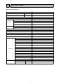
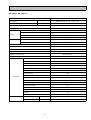
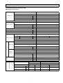
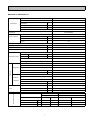
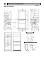
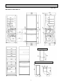
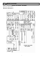
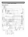
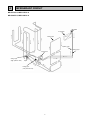
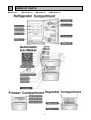
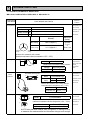
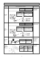
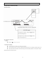
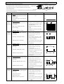
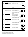
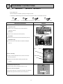
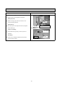
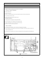
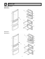
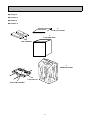
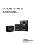
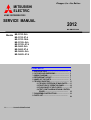
Changes for the Better
MITSUBISHI
ELECTRIC
HOME REFRIGERATORS
SERVICE MANUAL
2012
NO.SM-RE-1206
Models MR-C375C-W-A
MR-C375C-ST-A
MR-C375C-OB-A
MR-C375CL-W-A
MR-C375CL-ST-A
MR-C405C-W-A
MR-C405C-ST-A
MR-C405CL-W-A
MR-C405CL-ST-A
CONTENTS
1. SPECIFICATIONS.................................................... 1
2. OUTLINES AND DIMENSIONS.................................. 3
3. WIRING DIAGRAM.................................................... 5
4. REFRIGERANT CIRCUIT........................................... 7
5. NAMES OF THE PARTS........................................... 9
6. TROUBLE SHOOTING.............................................. 11
6.1 TROUBLE CRITERION OF MAIN PARTS.......11
6.2 FUNCTION OF OPERATION PANEL..............14
6.3 FLOW CHART OF SELF-CHECK....................15
6.4 TEST POINT DIAGRAM OF MAIN CONTROL
BOARD........................................................ 18
7. DISASSEMBLY INSTRUCTIONS............................... 19
8. PARTS LIST............................................................ 24
A………….......Australia & New Zea land
1
SPECIFICATIONS
1-1 SPECIFICATIONS
MR-C375C-A, MR-C375CL-A
Power supply
Total capacity
Dimensions (HXWXD)
Cabinet
Food liner
Cabinet
Refrigerator door
Insulation
Vegetable door
Freezer door
Cooling system Freezer
Refrigerator
Evaporator
Condenser
Defrost system
Drain
Temperature control system
Refrigerator room light
230-240V 50Hz
GROSS (AS) 375 (R : 197 V : 75 F : 103)
1678 x 600 x 656
Acrylic resin coated steel
ABS resin
Foamed cyclopenthane
Foamed cyclopenthane
Foamed cyclopenthane
Foamed cyclopenthane
Forced air convection
3 way air flow
Fin and tube type
Concealed type
Automatic (Defrost heater )
Automatic (drainage)
Automatic control
240V, 15W (E12)
1 pc.
1 pc.
1 pc.
1 pc.
2 pcs.
1 pc.
1 pc.
1 pc.
1 pc.
1 pc.
1 pc.
1 pc.
1 pc.
1 pc.
1 pc.
69
75
L
mm.
Glass shelf (R)
Slide shelf
Slide chilled case
Water tank
Free pocket (L)
Egg case
Accessories
Bottle pocket
Vegetable case
Fruit case
Freezing case (UP)
Freezing case (LOW)
Ice box sheet
Weight
Ice spoon
Ice box
Kick plate
Unit
Shipping
kg
kg
1
MR-C405C-A, MR-C405CL-A
Power supply
Total capacity
Dimensions (HXWXD)
Cabinet
Food liner
Insulation
Cooling system
L
mm.
Cabinet
Refrigerator door
Vegetable door
Freezer door
Freezer
Refrigerator
Evaporator
Condenser
Defrost system
Drain
Temperature control system
Refrigerator room light
Glass shelf (R)
Slide shelf
Slide chilled case
Water tank
Free pocket (L)
Egg case
Accessories
Free pocket (S)
Bottle pocket
Vegetable case
Fruit case
Freezing case (UP)
Freezing case (LOW)
Weight
Ice box sheet
Ice spoon
Ice box
Kick plate
Unit
Shipping
kg
kg
2
230-240V 50Hz
GROSS (AS) 405 (R : 227 V : 75 F : 103)
1798 x 600 x 656
Acrylic resin coated steel
ABS resin
Foamed cyclopenthane
Foamed cyclopenthane
Foamed cyclopenthane
Foamed cyclopenthane
Forced air convection
3 way air flow
Fin and tube type
Concealed type
Automatic (Defrost heater )
Automatic (drainage)
Automatic control
240V, 15W (E12)
2 pcs.
1 pc.
1 pc.
1 pc.
2 pcs.
1 pc.
1 pc.
1 pc.
1 pc.
1 pc.
1 pc.
1 pc.
1 pc.
1 pc.
1 pc.
1 pc.
73
80
1-2 ELECTRICAL PARTS SPECIFICATION
MR-C375C-A , MR-C375CL-A
Compressor
Model
Power supply
Rated input
Starting current
Rated current
Winding resistance (A.T. 20 oC)
W
A
A
PTC RELAY
Motor protector
Model
Ambient temperature
Time
Current
o
C
Sec.
A
Running capacitor
Capillary tube
Dehydrant Molecular sieve
Refrigerant HFC. 134a
Defrosting timer
Defrost finish
Defrosting control Thermal fuse
Defrost heater
Deodorizing function of defrost heater
Model
Type
Refrigerator Rate Voltage
Input
Revolution
Model
Type
Machine
Rate Voltage
Chamber
Input
Revolution
Vegetable case heater
Heater
Water pipe heater
Drain pipe heater
mm.
g
g
o
o
W
r.p.m
Temperature control
Fan motor
Dial position
LOW
MID
HI
o
C
C
o
C
o
C
C
W
r.p.m
W
W
W
Thermistor F
Freezer
ON
OFF
-9.2
-15.7
-14.0
-20.0
-16.0
-21.9
3
DHS66C10RAW
220-240V, 50Hz
113/113.5(220/240V 50Hz)
7.78/8.55(220/240V 50Hz)
0.70/0.64(220/240V 50Hz)
18.4 Ω (Main) / 18.5 Ω (Aux)
PTH7M330MD2
5TM718MFBYY-53
25
16 MAX
4.2
4µF 400VAC
∅ 1.8 X ∅ 0.6 X 2350
10
170
Control board
Thermister 14 + 1.5
73
372 Ω (240V, 155W)
Not equipped
FBA12J12VXC
DC brushless
12 VDC
4.2 (12 VDC)
2300 (12 VDC)
4715JL04WS16G51
DC brushless
12 VDC
1.44 (12 VDC)
1450 (12 VDC)
6
0.9
6
Thermistor R
Refrigerator
OPEN
7.0
4.2
1.6
SHUT
5.1
2.3
-0.2
MR-C405C-A, MR-C405CL-A
Compressor
Model
Power supply
Rated input
Starting current
Rated current
Winding resistance (A.T. 20 oC)
W
A
A
PTC RELAY
Motor protector
Model
Ambient temperature
Time
Current
o
C
Sec.
A
Running capacitor
Capillary tube
Dehydrant Molecular sieve
Refrigerant HFC. 134a
Defrosting timer
Defrost finish
Defrosting control Thermal fuse
Defrost heater
Deodorizing function of defrost heater
Model
Type
Refrigerator Rate Voltage
Input
Revolution
Model
Type
Machine
Rate Voltage
Chamber
Input
Revolution
Vegetable case heater
Heater
Water pipe heater
Drain pipe heater
mm.
g
g
o
o
W
r.p.m
Temperature control
Fan motor
Dial position
LOW
MID
HI
o
C
C
o
C
o
C
C
W
r.p.m
W
W
W
Thermistor F
Freezer
ON
OFF
-9.2
-15.7
-14.0
-20.0
-16.0
-21.9
4
DHS66C10RAW
220-240V, 50Hz
113/113.5(220/240V 50Hz)
7.78/8.55(220/240V 50Hz)
0.70/0.64(220/240V 50Hz)
18.4 Ω (Main) / 18.5 Ω (Aux)
PTH7M330MD2
5TM718MFBYY-53
25
16 MAX
4.2
4µF 400VAC
∅ 1.8 X ∅ 0.6 X 2350
10
170
Control board
Thermister 14 + 1.5
73
372 Ω (240V, 155W)
Not equipped
FBA12J12VXC
DC brushless
12 VDC
4.2 (12 VDC)
2300 (12 VDC)
4715JL04WS16G51
DC brushless
12 VDC
1.44 (12 VDC)
1450 (12 VDC)
6
0.9
6
Thermistor R
Refrigerator
OPEN
7.4
4.5
1.9
SHUT
5.4
2.6
0.1
2
OUTLINES AND DIMENSIONS
Unit : mm
MR-C375C-A, MR-C375CL-A
PLUG CORD LENGTH
600
20
124
1678
20
666
5
5
100
REQUIRED SPACE FOR INSTALLATION
50
381
Unit : mm
MR-C405C-A, MR-C405CL-A
PLUG CORD LENGTH
600
20
1248
1798
20
381
666
6
5
100
REQUIRED SPACE FOR INSTALLATION
50
3
WIRING DIAGRAM
(SKELETON WIRING DIAGRAM)
MR-C375C-A, MR-C375CL-A
MR-C405C-A, MR-C405CL-A
7
(ACTUAL WIRING DIAGRAM)
MR-C375C-A, MR-C375CL-A
MR-C405C-A, MR-C405CL-A
Remark
GY
W
R
SB
P
LB
V
=
=
=
=
=
=
=
GRAY
WHITE
RED
SKY BLUE
PINK
LIGHT BROWN
VIOLET
BK
OR
Y
YG
LG
BY
BU
=
=
=
=
=
=
=
BLACK
BR = BROWN
ORANGE
YELLOW
YELLOW/GREEN
LIGHT GREEN
BRIGHT YELLOW
BLUE
8
4
REFRIGERANT CIRCUIT
MR-C375C-A, MR-C375CL-A
MR-C405C-A, MR-C405CL-A
Muffler
Evaporator
Cabinet pipe
Capillary tube
Suction pipe
Compressor
Charge pipe
(High pressure side)
Dryer
Charge pipe
(Low pressure side)
9
5
NAMES OF PARTS
MR-C375C-A
MR-C375CL-A
MR-C405C-A
10
MR-C405CL-A
6 TROUBLE SHOOTING
6.1 TROUBLE CRITERION OF MAIN PARTS
MR-C375CC-AMR-C375CL-A MR-C405C-A MR-C405CL-A
Components
/ Part Name
Parts
Mounted
Position
Check Method and Criterion
Compressor in
Compressor
Model
DHS66C10RAW
the machine
Rated input
W
113/113.5(220/240V 50Hz)
chamber at the
Starting current
A
7.78./8.55(220/240V 50Hz)
rear side of
Rated current
A
0.70/0.64(220/240V 50Hz)
the frame
Abnormal
(faulty)
Normal
Auxilialy
wiring
Main wiring
18.4 Ω (Approx.)
Auxilliary wiring
18.5 Ω (Approx.)
Opened
(∞ Ω )
or
Short (0Ω)
Main
wiring
Measure the resistance with a tester.
(Ambient temperature:Room temperature 15oC ~ 25oC)
Run capacitor
400VAC
Rated input
Measure the resistance with a tester.
protector
Abnormal(faulty)
4 µF
Short (0Ω )
Compressor in
Therminal check point
1
3
Motor
Normal
In the control
panel of the rear
side at
compressor
room
5TM718MFBYY-53
Model
Connected
Point
Open
Close
o
120 + 5 C
o
69 + 9 C
Measure the resistance with a tester.(Ambient
temperature:Room temperature 15oC ~ 25oC)
Normal
the machine
chamber at the
rear side of
the frame
Abnormal(faulty)
Less than 1Ω Opened (∞ Ω )
PTC Relay
Compressor in
5
2
6
3
2
3
6
5
Model
PTH7M330MD2
the machine
Measure the resistance with a tester.
chamber at the
(Ambient temperature:Room temperature 15oC ~ 25oC)
rear side of
Normal
Abnormal(faulty)
33 Ω (Approx.)
Opened (∞ Ω ) or Short (0Ω)
As PTC Relay has been heated while refrigerator is running be sure
to measure the resistance after the thermistor has got cool enough.
11
the frame
Components/
Part Name
Check Method and Criterion
Parts Mounted Position
Model
FBA12J12VXC
Type
DC brushless
In the fan grille of
the refrigerator
compartment.
o
Measure the resistance with a tester.(Ambient temperature:Room temperature 15 C ~ 25oC)
Normal
Refrigerator
fan motor
Abnormal (faulty)
Between 3 - 1 (GND
and Vcc): About 25kΩ
Between 3-1 : open( ∞ Ω )
or
between 2-1 : short ( 0 Ω)
Model
4715JL04WS16G51
Type
DC brushless
In the machine
chamber at the rear
side of the frame.
Measure the resistance with a tester.(Ambient temperature:Room temperature 15oC ~ 25oC)
Normal
Machine
chamber fan
motor
Abnormal (faulty)
Between 3 - 1 (GND
and Vcc): About 25kΩ
Between 3-1 : open( ∞ Ω )
or
between 2-1 : short ( 0 Ω)
Measure the resistance with a tester.(Ambient temperature:Room temperature 15oC ~ 25oC)
Water pump
motor
(DC 5V)
Motor
damper for
refrigerator
compartment/
slide
compartment
Normal
Abnormal (faulty)
16 Ω (Approx.)
Open (∞Ω) or
short circuit (0Ω)
Measure the resistance with a tester.(Ambient temperature:Room temperature 15oC ~ 25oC)
Winding
(Blue-White,
Red-Yellow)
12
Under the water
tank holder in
refrigerator
compartment.
Normal
Abnormal
(faulty)
415 Ω
(Approx.)
Open (∞ Ω )
or short
circuit (0Ω)
In the fan grille of
the refrigerator
compartment.
Components/
Part Name
Parts Mounted
Position
Check Method and Criterion
Measure the resistance with a tester.(Ambient temperature:Room temperature 15oC ~ 25oC)
Black
Black
Water pipe
heater
Operation method
Normal
Abnormal (faulty)
1.3 kΩ (Approx.)
Open (∞ Ω )
At the left
bottom of
vegetable
compartment
The heater is turned on when the temperature of tray
for automatic ice making tray is about 10 oC or less
Rated input
operation method
Defrost
Heater
155 W
Power ON after defrosting
o
(14 + 1.5 C or more)
Measure the resistance with a tester.
In the drip tray
under the
evaporator of the
freezer
compartment
(Ambient temperature:Room temperature 15oC ~ 25oC)
Normal
Abnormal (faulty)
372Ω (Approx.)
Opened ( ∞ Ω )
Measure the resistance with a tester according to the following graph.
(Thermistor resistance values against temperature)
(Defrost thermistor)
Evaporator
Resistance measured under the ambient temperature from -50oC to +50 oC
1. 200 Ω to 500kΩ ............normal
2. Out of the above range ............abnormal
(kΩ)
35
30
Thermistor resistance will vary
Outside air thermistor
25
15
Take the temperature around the
(Freezer
compartment
thermistor and Ice
making tray
thermistor) In Ice
maker of freezer
compartment
thermistor resistance using a
tester.
The relation between resistance
and temperature is as shown on
Inner
thermistor
10
with the change of temperature.
thermistor, and then measure
Refrigerator
compartment,
Freezer
compartment,
,Defrosting,
Ice making
20
Thermistor
Thermistor Check Procedure
Thermistor resistance valves against
temperature
the left side.
5
(Refrigerator
compartment
thermistor) In the
control panel of
refrigerator
compartment
0
-20
-10
10
0
Temperature
20
30
Trouble shooting with self-check
(1) If the self - check indicates the abnormality of thermistor right after the power is
turned on, measure the resistance of the thermistor.
If the circuit of thermistor is short , check the element of the thermistor and the
contact of the connector.
(2) When the self - check indicates the abnormality of thermistor a few seconds
after the power is turned on , check the contact of the connector.
13
(Outside air
thermistor) In the
buzzer board (check
board)
6.2 FUNCTION OF OPERATION PANEL
(1) Normal operation
(2) Ice making test / Self-check
2.1 Setting
Press the
switch for 5 seconds
2.2 Operation and display
During automatic ice making test,ice making stop LED blink.
When somthing is faulty, the trouble is indicated with blinking number of ice making stop LED.(See page 13,14)
Self-check finishes automatically. LED trouble display is also automatically released 10 minutes later. However,
the abnormal part has not been repair yet.
14
6.3 FLOW CHART OF SELF-CHECK
(1) Trouble shooting with self-check
This refrigerator has self-check feature to clarify and indicate where & what the trouble is. It can be checked that
there is something wrong with electronic circuit and electric parts.
Ice making
stop LED Refrigerator Freezer
Self-check
Refrigerator room
Press Ice making stop button
Slide room
Ice maker off
No
Was trouble
displayed?
Yes
Locate the trouble according to
LED indication.(See page
Disconnect power plug
Repair/replace defective part(s)
according to LED indication
Connect power plug ∗
No
Check the parts whose
Abnormalities cannot be
detected by selfcheck.(Remark.1)
Yes
Self-check is finished.
∗ Wait 10 minutes before
inserting the cord once it's
unplugged.(If the cord is
plugged in within 10
minutes,trouble may be
display.)
Is trouble no longer
displayed?
Press Ice making stop button
Self-check ,Ice making stop LED
blink during the operational test
of automatic ice maker.
Is error no
longer
displayed?
No
Remark
1.) Self-check cannot detect abnormalities of the
following parts. See page 11~13 for trouble
criterion of main parts.
- Freezer & refrigerator door sw NG
- Thermo heater NG ( Water pipe / Vegetable
case heater etc.)
- Motor damper NG
- Water pump motor NG
2.) If the abnormality is found when power is
turned on, compressor and fan motor will be
suspended for 20 minutes.
During the ice making test
mode,watch the operation of ice
maker gear box and water pump in
refrigerator.
(2) Timing of self-check
Defrost heater and related parts : Self-check is conducted after defrosting.(Make sure to confirm the display before unplugging
because it is automatically reset once the power cord is pulled out.)
Ice maker and related parts :
To check the ice- making and then, check the blink amount of LED see the reference as (3)
Fan motor and related parts :
To check the blink amount of LED see the reference as (3)
Thermistor and related parts :
Self-check is continuously working.
Caution: The self-check will automatic start to begin power supply. But in the portion of the abnormality show the detail as (3) .
And the caution checking couldn't be summarized, please use self-check means by using operation panel.
15
(3) LED trouble display and the check point
(3.1) LED trouble display : follow the procedure of "self check method
Ice making
stop LED Refrigerator Freezer
Refrigerator room
and its operation" at page 11. Trouble is indicated by the blinking number
of ice making stop LED.
∗ When several troubles occur, smaller blinking number of LEDs has to be indicated first.
Slide room
Ice maker off
(3.2) Check point and treatment
Function
Explanation
Detecting method and corrective NG points
Normal
NO
1. Normally display and the Auto ice-maker
system display.
* If non-power supply, it'll show as same
the effect.
Auto ice maker NG
Blink
1. The connector lead wire of Auto ice maker 1. Check all points of the Auto ice maker
0.1 second is not orderly.
connector lead wire. May be un-lock
and struck insert.
2. Auto ice maker (Motor's not rotate
2. Replace and re-check the Auto ice
and non-display)
maker.
3. Replace and re-check the PCB plate
( Ref Con assy)
3. PCB plate ( Ref Con assy) NG
Thermistor(I) NG
Blink
1. Check all points of the thermistor (I)
1. The connector thermistor (I) lead wire
0.3 seconds isn't orderly.
connector lead wire, may be unlock
Off
2. Thermistor (I) NG (break or short)
3. PCB plate (Ref Con assay) NG
1 Blink
Thermistor (F) NG
1. The connector thermistor (F) lead wire
isn't orderly.
2. Thermistor (F) NG (break or short)
3. PCB plate (Ref Con assy) NG
2 Blinks
Thermistor (DEF) NG
1. The connector DEF. thermistor lead wire
isn't orderly.
2. Thermistor (DEF) NG (break or short)
3. PCB plate (Ref Con assy) NG
3 Blinks
Defrost heater NG
1. The Defrost heater connector lead wire
isn't orderly.
2. Defrost heater break or
Thermal fuse break.
3. PCB plate (Ref Con assy) break.
and struck insert.
2. If the resistance of thermistor (I) is NG,
should be changed the thermistor and
re-check the resistance.
3. If the resistance is OK,should be changed
PCB plate (Ref Con assy and re-check
the resistance).
Display function of LED
Light
No Light
0.1 sec
No Light
0.3 sec
0.3 sec
Light
No Light
1. Check all points of the thermistor (F)
connector lead wire, may be unlock
and struck insert.
2. If the resistance of thermistor (F) is
NG,should be changed the thermistor and
re-check the resistance.
3. If the resistance is OK,should be changed
PCB plate (Ref Con assy and re-check
the resistance.
0.1 sec
Light
0.3 sec
5 sec
Light
1
1
No Light
1 Cycle
1. Check all points of the thermistor
(DEF) connector lead wires, may be
unlock and struck insert.
2. If the resistance of thermistor (DEF) is
NG,should be changed the thermistor and
re-check the resistance.
3. If the resistance is OK,should be changed
PCB plate (Ref Con assy and re-check
the resistance.
0.3 sec
5 sec
Light
1
2
1
2
No Light
1 Cycle
1. Check all points of the defrost heater
connector lead wire, may be un-lock
and struck insert.
2. Check the resistance of the defrost heater
and thermal fuse.
3. If the resistance is OK,should be changed
PCB plate (Ref Con assy and re-check
the resistance.
16
1 Cycle
Light
1
2
3
1
No Light
0.3 sec
5 sec
Function
Explanation
Detecting method and corrective NG points
Display function of LED
Thermistor (R) NG
4 Blinks
1. The Thermistor (R) connector lead wire
isn't orderly.
2. Thermistor (R) NG (break or short)
3. PCB plate (Ref Con assy) NG
1. Check all points of Thermistor (R) connector
lead wire, may be unlock and struck insert.
2. If the resistance of Thermistor (R) is NG,
should be replaced the Thermistor (R) and
re-check the resistance.
3. If the resistance is OK., should be replaced
PCB plate (Ref Con assy) and re-check the
resistance.
1 Cycle
Light
1
3
2
4
No Light
0.3 sec
5 sec
Thermistor (A.T.) NG
6 Blinks
1. The Thermistor (A.T.) connector lead
wire isn't orderly.
2. Thermistor (A.T.) NG (break or short)
3. PCB plate (Ref Con assy) NG
Fan motor (Fan grille assy) NG
10 Blinks 1. DC motor is orderly connected.
2. DC motor NG (Motor un-rotate and
non-display)
3. PCB plate (Ref Con assy) NG
Fan motor (Outer motor assy) NG
11 Blinks 1. DC fan motor is orderly connected.
2. DC fan motor NG (Motor un-rotated,
and non-display.)
3. PCB plate (Ref Con assy) NG
PCB plate (Ref Con assy) NG
16 Blinks 1. PCB program (Ref Con assy) is NG
1. Check all points of the thermistor (A.T.)
connector lead wire, may be unlock and
struck insert.
2. If the resistance of Thermistor (A.T) is NG,
should be replaced the Thermistor (R)
and re-check the resistance.
3. If the resistance is OK., should be replaced
PCB plate (Ref Con assy) and re-check the
resistance.
1 Cycle
Light
1
2
6
1
2
1
2
1
2
1
2
1
2
No Light
0.3 sec
1 Cycle
1. Check all points of DC motor connector
lead wire, may be unlock and struck insert.
2. Replace DC motor (Fan grille assy) and
re-check display.
3. If the resistance is OK., should be replaced
PCB plate (Ref Con assy) and re-check the
resistance.
Light
1
2
10
No Light
0.3 sec
1 Cycle
1. Check all points of DC Fan motor connector
lead wire, may be unlock and struck insert.
2. Replace DC fan motor (Outer motor assy)
and check display.
3. If the resistance is OK., should be replaced
PCB plate (Ref Con assy) and re-check the
resistance.
Light
1
2
11
No Light
0.3 sec
1 Cycle
1. Replace a new PCB plate (Ref Con assy)
Light
1
2
16
No Light
0.3 sec
Refrigerant circuit is NG.
19 Blinks 1. Pipe cracked (Welding joint)
1 Cycle
1. Check and corrective to each problem.
2. Gas leak
3. Compressor NG
Light
1
2
19
No Light
0.3 sec
Remark :
1.) For the refrigerator is NG more than one case, will show as the first symptoms before, such as Thermistor (F) NG (1 blink in 0.3 seconds) and
Thermistor (R) NG (4 blinks in 0.3 seconds). LED will blink 1 blink in 0.3 seconds until Thermistor (F) was corrected. Then change to 4 blinks in 0.3 seconds
and LED won't blink when Thermistor (R) was corrected.
2.) Ice making stop LED blink during the operational test for ice maker.
3.) Compressor won't work if the fridge have problem and LED blink.
4.) Characteristic value may be changed due to the product improvement.
17
6.4 TEST POINT DIAGRAM OF MAIN CONTROL BOARD
MR-C375C-A
MR-C375CL-A MR-C405C-A
MR-C405CL-A
Parts Name
CN4K Lead color
1
2 Red
Damper
3 Gray
Ice Maker Positon SW
4 Bright Yellow Damper
5 Pink
Ice Maker & Water Pump Forward
6 White
Damper
Ice Maker Reverse
12 VDC 7 Brown
8 Blue
Damper
9
10 Yellow/Green Water Pump
5 VDC
CN1A Lead color
1 Grey
3 Black
Parts Name
CN2A Lead color
1 Grey
3 White
5 Red
Parts Name
220 VAC Common
Compressor
Defrost Heater
Lead color
Yellow
Yellow/Green
Brown
Sky Blue
Parts Name
Lamp
V Heater
Ice Maker Heater
Pipe Heater
CN3A
1
3
5
7
CN7M Lead color
1 White
2 Red
3 Violet
4 Sky Blue
5 Grey
Lead color
Parts Name
Violet
12 VDC Common
Violet
12 VDC Common
Black
GND
Pink
GND
Orange
Outer Fan Motor FG
Bright Yellow Inner Fan Motor FG
Light Green Outer Fan Motor Vs
White
Inner Fan Motor Vs
Parts Name
CN6S Lead color
1
2
3
4 Yellow
Ice Maker Stop SW
5 Red
Ice Maker Stop LED
6
7
8 Blue
F Thermistor
9 Bright Yellow Temp Control Board
10 Orange
R Thermistor
11 Gray
Temp Control Board
12 Light Green I Thermistor
13 Sky Blue
5 VDC Common
14 Pink
DEF Thermistor
15 Black
GND
16 Brown
Door SW
220 VAC
Parts Name
12 VDC Common
Buzzer
A.T. Thermistor
5 VDC Common
Compulsion DEF
CN5F
8
7
6
5
4
3
2
1
Compulsory defrosting method have 2 methods as below
1) Short circuit at 2-pin connector between no.6 (white wire) with no.7 (red wire)
at Buzzer & Thermistor A.T. board.(Inside hinge cover)
2) Open door R and then adjust dial freezer at MID position. Use magnet touch
door switch in order to simulate as door closing. (lamp must no light),then turn
the dial continuously as follow COLDER → LOW → MID
18
7
DISASSEMBLY INSTRUCTIONS
MR-C375C-A
MR-C375CL-A
MR-C405C-A
MR-C405CL-A
Plug out before work.
Check the automatic ice-maker by pressing ice making stop switch.
In assembling & disassembling parts use several kind of screws and rivets. Do not mistake to use them.
A
B
4 x12 Stainless steel
D
C
Rivet
4 x12 (Black) With metal washer
Rivet
OPERATING PROCEDURE
PHOTOS
1. Detachment Control PCB parts
Photo 1
7 fixing screws
Compressor cover
(1) Detach 7 pcs. of compressor cover screws behind the
refrigerator. (Photo 1)
Compressor
cover
Elect cover
(2) Detach 4 pcs. of Elect cover screws. (Photo 2)
Elect attach
4 fixing screws
Photo 2
(3) Disconnect the connector and remove Elect attach. (Photo 3)
PCB (Refcon assy)
(4) Remove the catch of elect attach to release the PCB plate.
(Photo 3)
Elect cover
Photo 3
Catch
PCB
Caution on assembly
Elect attach
[1] Firmly connect the lead wire and the connector. Ensure the
wire are not pinched.
Catch
[2] Please use the new material of sealing insulation when
re-attach.
2. Detachment Lamp cover parts
Photo 4
Catch
(1) Remove parts inside the refrigerator Shelf 1,2,3 shelf
Lamp cover inside the refrigerator
(1) Push up the lower catch, and pull the room light cover toward you.
Lamp cover
(2) Detach two upper catches to take out the cover (Photo 4)
Catch
19
OPERATING PROCEDURE
3.
PHOTOS
Detachment the Vegetable case parts
Photo 5
(1) Detach parts inside vegetable compartment (Vegetable case, Fruit case).
Catches
Vegetable
case cover
(2) Detach the door of vegetable compartment.
(3) Detach rivet (C) at the right and unhooking 2 catches at front,
(center and left). (Photo 5)
Rivet
Caution on assembly
[1] Be sure to put vegetable case cover on the catches at the rear of
V-room
vegetable compartment.
Catch
Catch
Water pump motor
(4) Remove two screws and cut the lead wire of water-pump motor to
detach it.
4.
Detach the refrigerator room parts
Photo 6
(1) Detach parts inside the refrigerator compartment.
Screw
Screw
(2) Detach parts inside the vegetable compartment.
Fan grille
(3) Detach a left screw of mirror hinge and pull out the lead wire.
F-room
(Photo 7)
(4) Detach the connector.
Control panel , Duct R, Temperature control panel
Photo 7
(5) Remove the upper and lower rivets (C) of right side and left side,
Catch
Catch
Catch
then unhook 7 catches.(9 catches for C405B)
* Remove the right catch before push the control panel to the right
and detach it. (Photo 7)
Rivet
Rivet
Lamp
Catch
Catch
Screw
Fan grille
Control panel
(6) Remove the following; Screw (A) at the upper and right center,
2 screws (B) at the left and 2 screws (B) at the right. (Photo 6)
Catch
Catch
(only:C405B)
(only:C405B)
* Motor damper and thermal fuse are combined with fan grille.
Catch
* Fan and fan motor are combined with fan grille.
Rivet
Catch
Rivet
Mirror hinge
Caution on assembly
[1] Use new tapes and sealing materials for assembly.
[2] Putting some tape across joints, tape them securely so that they will
not leak the cool air.
[3] Attach a connector securely in order to prevent contact failure.
20
R-room
OPERATING PROCEDURE
Defrost heater, Drip tray
PHOTOS
Aluminium
Photo 8
Drip tray
(7) Peel off the tape that fixes lead wires on the side wall
of the vegetable compartment. Then take out defrost heater
Tape
Tape
together with heater roof.
Detach heater roof and Heater cover from Defrost heater.
Heater roof
Detach the drip tray after removing the defrost heater.
Defrost thermistor
(8) Cut the binder and disconnect the connector. (Photo 9)
Heater
Defrost
heater
Photo 9
Caution on assembly
Evaporator
DEF thermistor
[1] Loosen the lead wire at the defrost heather to prevent
water from entering the glass tube and careful the
direction for the correct assembly.
[2] Attach the drip tray securely to the lower parts.
[3] Attach the defrost thermistor in the correct place. (If
Defrost heater
they're attached out of place, thermal characteristics
will go wrong).
[4] Attach the lead wires to the fixture.
5
Detachment the parts in Freezer compartment
Photo 10
(1) Detach the parts inside the Freezer room (Ice spoon,
Rivet
Freezing case [upper] and Freezing case [lower] ).
Cover (upper)
Catch
(2) Pull the door of Freezer compartment by pulling toward you.
Cover (upper)
(3) Detach 3 catches and remove it. (Photo 10)
Rivet
Ice corner
(4) Disconnect the connector.
Catch
Automatic ice-maker
F-room
(5) push a catch to upper and pull the part to the right
and detach it. (Photo 10)
21
OPERATING PROCEDURE
6
Detachment the vegetable compartment parts
PHOTOS
Photo 11
(1) Detach the door of the vegetable compartment.
Water pipe (lower)
(2) Detach a rivet (C), pipe cover and connector. Then
Pipe cover
remove the water pipe lower.
Water tank tray
Water pipe
(3) Pull Tank tray to R-room upper and take it out together
with the water pipe.
Vegetable case room
Photo 12
Caution on assembly
Water pipe
(1) Fit the water tank tray properly in order to prevent a
water leak.
Door Switch
R-room
(4) Insert a minus screwdriver between switch and body
to remove the door switch.
22
Tank tray
OPERATING PROCEDURE
Compressor cover
(1) Remove 7 screws for compressor cover at the back of the refrigerator.
Fan motor of compressor compartment
(2) Detach the Elect cover
(3) Detach the Connector.
(4) Remove a screw that fixed bell mouth. Pull out the whole fan motor and disconnect the terminals.
(5) Pull out the fan from the fan motor.
(6) Detach the lid-fixing screw to take out the fan motor.
7 Detachment compressor.
(1) Collect gas from the charge pipe on the high pressure side.
(2) After collecting gas, cut the charge pipe on the low pressure side.
(3) Detach the welded section of the discharge pipe and suction pipe.
(4) Replace the compressor and the dryer at a time.
Caution on assembly
(1) After attaching the compressor, must to Vacuum and charge gas from charge pipe.
(2) Arrage the piping so that the pipe will not hit each other and compressor cover, (which causes loud noise). Then
attach the compressor cover.
(3) After all the work is complete, be sure to check the cooling preformance and the gas leak from the welded points.
Attach U washer as the figure shown below
W
W
Dryer
W
W
W
W
W
W
: This mark shown welded point
23
Fan motor (Machine room)
Charge pipe(Low pressure side)
8
PARTS LIST
DOOR, BODY PARTS
MR-C375C-A
MR-C375CL-A
MR-C405C-A
MR-C405CL-A
24
NO. PART NO. RoHS
PART NAME
SPEC
MR-C375C-A
W
1
2
3
4
5
6
7
8
9
10
11
12
13
14
KIERL6000
KIER66000
KIER63000
KIERN6000
KIERN7000
KIERL8000
KIER71000
KIERP0000
KIERP1000
KIEPE2002
KIEP90002
KIEP91002
KIEPE2001
KIEP90001
KIEP91001
KIEG05741
KIEPE4741
KIEP89118
KIEP89151
KIEP89157
KIEP89119
KIEHJ3115
KIEP89110
KIEP94110
KIEP89124
KIEP89112
KIEP89111
KIERN0031
KIER72031
<G>
<G>
<G>
<G>
<G>
<G>
<G>
<G>
<G>
<G>
<G>
<G>
<G>
<G>
<G>
<G>
<G>
<G>
<G>
<G>
<G>
<G>
<G>
<G>
<G>
<G>
<G>
<G>
<G>
ST
OB
1
1
1
1
DOOR R
1
1
1
1
1
1
1
DOOR V
1
1
1
1
DOOR F
1
1
1
1
1
1
CATCHER RH
CATCHER LH
FREE POCKET L
FRAME V ASSY
FRAME F ASSY
FREE POCKET S
EGG CASE
MAGNET GASKET ASSY ( R )
BOTTLE POCKET
MAGNET GASKET ASSY ( V )
MAGNET GASKET ASSY ( F )
BADGE ASSY
FREEZER ROOM
REFRIGERATOR ROOM
1
1
1
1
1
1
1
2
1
1
2
1
1
2
1
1
1
2
1
1
1
2
1
1
1
1
1
1
1
1
1
1
1
1
1
1
1
1
1
1
1
1
1
1
1
1
1
1
1
1
1
1
1
RECOMMEND PART NO. 1, 2, 3, 10, 12, 13
ABBREVIATION
F
R
Q'TY/UNIT
PRICE/PIE
MR-C375CL-A MR-C405C-A MR-C405CL-A CE(US$FCA)
W
ST
W
ST
W
ST
V
VEGETABLE ROOM
ENCIRCLED PART NUMBER ARE NOT SHOWN IN THE FIGURES.
Remark
- Country code : A= Australia and New Zealand
- Colour code : W = White, ST = Stainless
25
1
1
1
1
2
1
1
1
1
2
1
1
1
1
1
1
1
1
1
1
1
1
1
1
1
1
2
1
1
1
1
1
2
1
1
1
1
1
1
1
1
1
1
1
1
1
1
BODY PARTS
MR-C375C-A
MR-C375CL-A
MR-C405C-A
MR-C405CL-A
26
Q'TY/UNIT
NO.
1
2
3
4
5
6
7
8
9
10
11
12
13
14
15
16
17
18
19
20
21
22
23
24
25
26
27
28
29
30
31
32
33
34
PART NO.
RoHS
PART NAME
SPEC
MR-C375CL-A
MR-C375C-A
KIEP89858 <G>
CONTROL PANEL
KIEP94858 <G>
KIEHJ3305 <G> THERMO DIAL (R)
KIEP89802 <G> DUCT V ASSY
KIEP89818 <G> COVER DUCT V
KIEP89503 <G> WATER TRAY ASSY
KIEP89808 <G> CONNECTOR COVER
KIEPE2663 <G> FAN GRILLE ASSY
KIEHJ3708 <G>
KIEP91708 <G> LABEL FC
KIEP90708 <G>
KIEP89442 <G> PIPE COVER
KIEPE2350 <G> AUTO ICE MAKER
KIEP89652 <G> COMP COVER ASSY
KIE805794 <G> CASTER SET
KIEHJ3709 <G> SCREW LABEL (F)
KIEH79795 <G> CASTER ASSY
KIEC02460 <G> ADJUST BOLT
KIER65705 <G>
KIEP91705 <G>
KIEP90705 <G> HINGE COVER
KIERN6705 <G>
KIEPE5705 <G>
KIEP89701 <G>
HINGE ASSY (UP)
KIEPE4701 <G>
KIEP89470 <G> LAMP COVER
KIEHJ4503 <G> JOINT PIPE (TANK)
KIEHJ3531 <G> WATER TANK CAP
KIEHJ3519 <G> WATER PUMP
KIEK96527 <G> WATER TANK COVER ASSY
KIEMT0702 <G>
HINGE ASSY (LOW)
KIEHJ2702 <G>
KIEHJ3798 <G> ROLLER
KIEHJ3520 <G> WATER TANK
KIEHJ3526 <G> FILTER (TANK)
KIEP89328 <G> ELECT BOX COVER ASSY
KIEMQ4326 <G> ELECT BOX SUB ASSY
KIEHJ4442 <G> COVER (IM)
KIEPE2730 <G>
KIEP91730 <G> KICK PLATE
KIEP90730 <G>
KIEPJ5663 <G> FAN GRILLE
KIEP94662 <G> BELL MOUTH
KIEHJ4682 <G> DUCT DAMPER
KIEP89336 <G> THERMAL FUSE ASSY
RECOMMEND PART NO. 7, 20, 22, 34
ABBREVIATION
W
ST
OB
W
ST
1
1
1
1
1
2
1
1
1
1
1
1
2
1
1
1
1
1
2
1
1
1
1
1
2
1
1
1
1
1
1
2
1
1
1
1
1
1
1
1
1
2
2
2
2
1
1
1
1
2
2
2
2
MR-C405C-A
W
ST
W
ST
1
2
1
1
1
1
1
1
1
2
1
1
1
1
1
1
2
1
1
1
1
1
1
1
2
1
1
1
1
1
1
1
1
1
1
2
2
2
2
1
1
1
2
2
2
2
1
1
1
2
2
2
2
MR-C405CL-A
1
1
1
1
2
2
2
2
1
1
1
1
1
2
2
2
2
1
1
1
1
2
2
2
2
1
1
1
2
2
2
2
1
1
1
1
1
1
1
1
1
1
1
1
1
1
1
1
1
1
1
1
1
1
1
1
1
1
4
1
1
1
1
1
1
4
1
1
1
1
1
4
1
1
1
1
1
1
1
1
1
1
1
1
1
1
1
1
1
1
4
1
1
1
1
1
1
1
4
1
1
1
1
1
1
1
1
1
1
1
1
1
1
F
FREEZER ROOM
IM
ICE MAKER
R
REFRIGERATOR ROOM
V
VEGETABLE ROOM
ENCIRCLED PART NUMBER ARE NOT SHOWN IN THE FIGURES.
27
1
1
1
1
1
1
1
1
1
1
1
1
1
1
1
4
1
1
1
1
1
1
4
1
1
1
1
1
1
1
1
1
1
1
1
1
1
1
1
1
1
1
1
1
1
1
1
1
1
1
1
1
1
1
1
4
1
1
1
1
1
1
1
4
1
1
1
1
1
1
1
1
1
1
1
1
1
1
1
1
1
1
1
1
1
1
1
PRICE/PIECE
(US$-FCA)
ELECTRICIAL PARTS
MR-C375C-A
MR-C375CL-A
MR-C405C-A
MR-C405CL-A
28
Q'TY/UNIT
NO.
1
2
PART NO.
RoHS
PART NAME
KIE402360
<G> LAMP
4
5
6
7
8
9
10
11
12
KIEHJ3365
KIEP89312
KIEHJ3378
KIEHJ3469
KIEHJ3316
KIEPE2354
KIEHJ3362
KIEP89364
KIELR4346
22
23
24
25
26
KIEMQ4363
KIEKA0382
KIEMQ4320
KIEP89537
KIEP89392
KIEP89397
KIEP89538
KIERN4339
KIERN8339
KIEP89340
KIEE76330
KIEG05341
KIEP89325
KIEP89662
1
1
1
1
1
1
1
1
1
1
1
1
1
1
1
1
1
1
1
1
1
1
1
1
<G> WATER PUMP
1
1
1
1
1
1
1
1
1
<G> THERMISTOR (DEF)
1
1
1
1
1
1
1
1
1
<G> THERMISTOR (F)
1
1
1
1
1
1
1
1
1
<G> GEAR BOX (IM)
1
1
1
1
1
1
1
1
1
<G> THERMISTOR (I)
1
1
1
1
1
1
1
1
1
<G> PLUG CORD ASSY
1
1
1
1
1
1
1
1
1
<G> REED SWITCH
1
1
1
1
1
1
1
1
1
<G> WATER PIPE ASSY
1
1
1
1
1
1
1
1
1
1
1
1
1
1
1
1
1
1
1
1
1
1
1
1
1
1
1
<G> LAMP SWITCH (R)
1
1
1
1
1
1
1
1
1
<G> TEMP CONTROL PANEL
1
1
1
1
1
1
1
1
1
<G> FAN MOTOR ASSY
1
1
1
1
1
1
1
1
1
<G> HEATER ROOF
1
1
1
1
1
1
1
1
1
<G> DEFROST HEATER
1
1
1
1
1
1
1
1
1
<G> HEATER COVER
1
1
1
1
1
1
1
1
1
<G> DRIP TRAY
1
1
1
1
1
1
1
1
1
<G>
1
1
1
1
1
1
1
1
1
<G> RUNNING CAPACITOR
240V 15W E12
1
1
1
13 KIEKA0374 <G>
21
SPEC
KIEHJ3313 <G> THERMISTOR (R)
KIEP89386 <G>
LAMP SOCKET
KIEP94386 <G>
3
14
15
16
17
18
19
20
PRICE/PIE
MR-C375CL-A MR-C405C-A MR-C405CL-A CE(US$MR-C375C-A
W ST OB W ST W ST W ST FCA)
4µF 400VAC
BUZZER BOARD &
THERMISTOR (A.T.)
REFCON ASSY
<G>
<G> MOTOR PROTECTOR
5TM718MFBYY53
1
1
1
1
1
1
1
1
1
PTH7M330MD2
1
1
1
1
1
1
1
1
1
<G> PROTECTOR COVER
1
1
1
1
1
1
1
1
1
<G> OUT FAN MOTOR ASSY
1
1
1
1
1
1
1
1
1
<G> BELL MOUTH M ASSY
1
1
1
1
1
1
1
1
1
<G> PTC RELAY
RECOMMEND PART NO. 1, 3, 5, 6, 8, 13, 15, 18, 21, 22, 23
29
ACCESSORY AND UNIT PARTS
MR-C375C-A
MR-C375CL-A
MR-C405C-A
MR-C405CL-A
30
RoHS
W
ST
1
2
3
4
5
6
7
8
9
10
11
12
13
14
15
16
17
18
19
20
<G> GLASS SHELF R ASSY
<G> SLIDE SHELF (REAR)
1
1
1
1
1
1
1
1
1
1
2
1
2
1
2
1
2
1
<G> SLIDE SHELF (FRONT)
1
1
1
1
1
1
1
1
1
<G> SLIDE CHILLED CASE
1
1
1
1
1
1
1
1
1
<G> VEGEATABLE CASE COVER
1
1
1
1
1
1
1
1
1
<G> FRUIT CASE
1
1
1
1
1
1
1
1
1
<G> ICE BOX SHEET
1
1
1
1
1
1
1
1
1
<G> ICE BOX
1
1
1
1
1
1
1
1
1
<G> FREEZING CASE (UP)
1
1
1
1
1
1
1
1
1
<G> ICE SPOON
1
1
1
1
1
1
1
1
1
<G> F CASE (LOW)
1
1
1
1
1
1
1
1
1
<G> GLASS SHELF R ASSY
1
1
1
1
1
1
1
1
1
<G> VEGEATABLE CASE
1
1
1
1
1
1
1
1
1
<G> EVAPORATOR
1
1
1
1
1
1
1
1
1
<G> ELBOW
1
1
1
1
1
1
1
1
1
1
1
1
1
1
1
1
1
1
1
1
1
1
1
1
1
1
1
1
1
1
1
1
1
1
1
1
<G> U WASHER
4
4
4
4
4
4
4
4
4
<G> RUBBER MOUTH
4
4
4
4
4
4
4
4
4
KIEP89420
KIEHJ3427
KIEHJ3428
KIEP89413
KIEP89409
KIEP89406
KIEP89468
KIEP89487
KIEP89474
KIEHJ3477
KIEP89475
KIEP89420
KIEP89405
KIEP89995
KIEP89504
KIEAA1980
KIEP89435
KIEPE2277
KIEHJ3735
KIEE76797
PART NAME
<G> DRYER
SPEC
Q'TY/UNIT
PRICE/PIE
MR-C375CL-A MR-C405C-A MR-C405CL-A CE(US$OB W ST W ST W ST FCA)
NO. PART NO.
MR-C375C-A
XH-9,10GR
<G> DRAIN PAN
<G> COMPRESSOR
DHS66C10RAW
RECOMMEND PART NO. 1, 2, 3, 4, 14, 16, 18
31
PACKING PARTS
MR-C375C-A
MR-C375CL-A
MR-C405C-A
MR-C405CL-A
NO STEP ON
6
C.F.B TOP COVER
R
1
C.F.B BOX ASSY
L
2
TOP CUSHION
3
PACKING COVER
4
BOTTOM CUSHION
5
C.F.B PALLET
32
NO. PART NO. RoHS
PART NAME
KIERN4970 <G>
1
2
3
4
5
6
KIERN5970
KIETY7970
KIERN6970
KIERN7970
KIERN8970
KIERN9970
KIERP0970
KIERP1970
KIEP89979
KIEHN8973
KIEP89978
KIEP89974
KIEP89975
SPEC
Q'TY/UNIT
PRICE/PIE
MR-C375CL-A MR-C405C-A MR-C405CL-A CE(US$OB W ST W ST W ST FCA)
MR-C375C-A
W
1
ST
1
<G>
1
<G>
1
<G>
<G> C.F.B BOX ASSY
1
1
<G>
1
<G>
1
<G>
<G>
<G> TOP CUSHION
<G> PACKING COVER
<G> BOTTOM CUSHION
<G> C.F.B PALLET
<G> C.F.B TOP COVER
1
1
1
1
1
1
1
1
1
1
33
1
1
1
1
1
1
1
1
1
1
1
1
1
1
1
1
1
1
1
1
1
1
1
1
1
1
1
1
1
1
1
1
1
1
1
1
MITSUBISHI ELECTRIC CORPORATATION
HEAD OFFICE : MITSUBISHI DENKI BLDG., MARUNOUCHI,TOKYO 100. TELEX : J24532 CABLE MELCO TOKYO
Distributed by
MITSUBISHI ELECTRIC AUSTRALIA PTY LTD.
(Incorporated in New South Wales) ABN 58 001 215 792
New South Wales :
348 Victoria Road,
Rydalmere NSW 2116
Ph : (02) 9684 7777
Fax : (02) 9898 1043
Queensland:
Unit 12, 469
Nudgee Road,
Hendra QLD , 4011
Ph : (07) 3263 2000
Fax : (07) 3630 1888
South Australia /
Northern territory :
Suite 1, 224 Glen Osmond Road
FULLARTON SA 5063
Ph: (08) 8338 1001
Fax : (08) 8338 0501
Western Australia :
329 Collier Road,
Bassendean WA 6054
Ph : (08) 9377 3400
Fax : (08) 9377 3499
Victoria / Tasmania :
Building 28, Omnico bus. Park
270 Ferntree Gully Road,
Notting Hill 3168
Ph : (03) 9535 7800
Fax : (03) 9535 7801
Far North
Queensland:
Capricorn Air,
13 Mackley St,
Garbutt 4814
Ph: (07) 4775 5222
Fax : (07) 4775 5303
Distributed by
BLACK DIAMOND TECHNOLOGIES LIMITED (BDT)
Wellington Office (Head Office)
1 Parliament Street
PO Box 30-772
Lower Hutt
Ph : (04) 560 9100
Fax : (04) 560 9133
Auckland Office
Unit1, 4 Walls Road
Penrose
Auckland PO Box 12-726
Ph: (09) 526 9340
Fax : (09) 526 9369
Christchurch Office
Suite 2, Level 1
37 Manderville Street
Christchurch PO Box 1604
Ph : (03) 341 7052
Fax : (03) 341 7054