1
ADAT Multicore Extender
ADX-32B
ADX-64B-PRO
User's Manual
CONTENTS
1. DEVICE OVERVIEW.................................................................................................................................................... 3
1.1. Front panel......................................................................................................................................................... 3
1.2. Rear panel.......................................................................................................................................................... 3
2. TYPICAL APPLICATION.............................................................................................................................................. 4
2.1. Digital snake (32 channels) with ADX-32B........................................................................................................ 4
3. IMPORTANT SAFETY NOTES.................................................................................................................................... 5
3.1. Cat5 connections............................................................................................................................................... 5
4. INTRODUCTION......................................................................................................................................................... 5
4.1. Features.............................................................................................................................................................. 5
4.2. Available models................................................................................................................................................ 6
4.3. Input and Return channel configuration............................................................................................................ 6
4.4. Daisy-chaining.................................................................................................................................................... 6
5. FRONT PANEL............................................................................................................................................................ 7
5.1. Cat5 Connection 1.............................................................................................................................................. 7
5.2. Cat5 Connection 2 (ADX-64B-PRO only)........................................................................................................... 7
6. REAR PANEL.............................................................................................................................................................. 8
6.1. POWER Connections......................................................................................................................................... 8
6.2. ADAT 1-4............................................................................................................................................................ 8
6.3. ADAT 5-8 (ADX-64B-PRO only).......................................................................................................................... 9
6.4. MIDI1.................................................................................................................................................................. 9
6.5. MIDI2 (optional in ADX-64B-PRO)..................................................................................................................... 9
6.6. Wordclock (ADX-64B-PRO only)...................................................................................................................... 10
7. DEVICE SYNCHRONIZATION................................................................................................................................... 11
7.1. General concept............................................................................................................................................... 11
7.2. Synchronization over ADAT............................................................................................................................. 11
7.3. Synchronization over coaxial cable................................................................................................................. 11
8. CABLE RECOMMENDATIONS................................................................................................................................. 12
8.1. Cat5 cable......................................................................................................................................................... 12
8.2. Toslink (Lightpipe) cable.................................................................................................................................. 12
9. DIGITAL SIGNAL QUALITY...................................................................................................................................... 13
9.1. Latency............................................................................................................................................................. 13
9.2. Jitter.................................................................................................................................................................. 13
10. EXAMPLE APPLICATIONS..................................................................................................................................... 14
10.1. Digital 24/8 multicore.................................................................................................................................... 14
10.2. Digital 48/16 multicore with monitoring and recording splits......................................................................15
11. SETTINGS OVERVIEW........................................................................................................................................... 16
12. SPECIFICATIONS.................................................................................................................................................... 17
13. APPENDIX.............................................................................................................................................................. 19
13.1.Warranty.......................................................................................................................................................... 19
13.2. Contact........................................................................................................................................................... 19
13.3. Recycling........................................................................................................................................................ 19
13.4. About this document..................................................................................................................................... 19
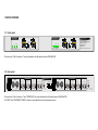
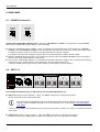
1. DEVICE OVERVIEW
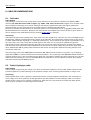
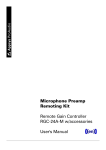
1.1. Front panel
Cat5 Connection 1
Cat5 Connection 2
1 (A/ B)
2 (A+B)
1 2 3 4
Power
ADAT Clock
A
Appsys ProAudio
1 (A/ B)
2 (A+B)
5 6 7 8
Termination
B
Power
ADX-32B / ADX-64B-PRO
32/64-ch ADAT® Multicore Extender
with MIDI and wordclock
Made in Switzerland
www.appsys.ch
ADAT Clock
A
Termination
B
ADAT is a registered trademark of Alesis Corp.
The connectors “Cat5 Connection 2“ are only available in the 64 channel version (ADX-64B-PRO).
5
Appsys ProAudio
6
7
8
SECONDARY
POWER
WORDCLOCK
ON
Cat5 Connection 1
MIDI1
1
2
4
3
PRIMARY
POWER
ON
IN
OUT/THRU
IN
OUT/THRU
IN
OUT/THRU
IN
OUT/THRU
IN
OUT/THRU
12V/1A
1 2 3 4 5 6
IN/OUT
IN
IN
IN
IN
IN
IN
IN
IN
OFF
WC
1 2 3 4 5 6
CH1
CH2
CH3
CH4
Cat5 Connection 2
MIDI2
OUT
OUT
OUT
OUT
OUT CH5/WC/MIDI
OUT
CH6
OUT
CH7
OUT
CH8
75Ω WC TERM
MULTI CH5 MODE
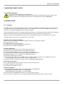
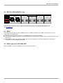
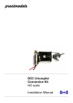
1.2. Rear panel
IN
OUT/THRU
IN
OUT/THRU
The connectors “Cat5 Connection 2” and “WORDCLOCK” are only available in the 64 channel version (ADX-64B-PRO).
The “MIDI2” and “SECONDARY POWER” connectors are installed only with the respective option.
IN
OUT/THRU
IN
OUT/THRU
IN
OUT/THRU
12V/1A
User's Manual
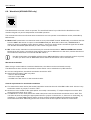
2. TYPICAL APPLICATION
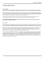
2.1. Digital snake (32 channels) with ADX-32B
The diagram below shows a typical application of the ADX devices: One Cat5 cable is used for both the
transmission of 24 channels from the stage to the mix console, and 8 channels in the opposite direction. All 32
channels are also fed into a monitor console and into a multi-track recorder. An additional MIDI channels allows
remote control of the devices (e.g. the multitrack recorder, or the gain control of the preamp).
Preamp/DAC/ADC
Preamp/DAC/ADC
Monitor
Monitormix
mix
MIDI for
remote control
ADX-32B
ADX-32B
Stage
ADX-32B
ADX-32B
Daisy-chain
for splitting
Analog
ADAT
MIDI
Cat5
32 channels
over one Cat5
ADX-32B
ADX-32B
Main
Mainmixer
mixer
FOH
4
ADX-32B
ADX-32B
Inputs can
be anywhere
Multitrack
MultitrackRecorder
Recorder
Recording
ADX-32B / ADX-64B-PRO
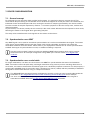
3. IMPORTANT SAFETY NOTES
3.1. Cat5 connections
Use the Cat5 cable ONLY between ADX devices.
NEVER connect an ADAT Multicore Extender to any Ethernet networking device (PC, Switch, other
network equipment)! The ADX device and/or the networking device may be DAMAGED!
4. INTRODUCTION
4.1. Features
The ADAT Multicore Extender (ADX) allows you to extend and bundle several ADAT connections into standard
Cat5 cable, covering up to 100m (330ft) in distance. One Cat5 cable carries up to four ADAT connections (32
channels), one channel of MIDI data, and a wordclock signal.
This makes the ADX a perfect cost-effective digital snake system. It seamlessly integrates with industry standard
ADAT equipment and provides a lightweight replacement for bulky and heavy analog multicores.
Thanks to its daisy-chain capability, it can also serve as distribution backbone for monitoring or recording.
The ADX system is superior to an analog snake in many ways:
Improved sound quality and reliability
No noise, hum, crackling etc. thanks to digital transmission and galvanic isolation
Very low latency (<1µs)
Redundant power supply (optional)
Precision clock recovery for best jitter performance
Quality product „Made in Switzerland“
Versatile connectivity
Up to 8 ADAT connections for the transmission 64 channels
Direction can be set individually for every ADAT connection
Daisy-chaining possible for easy signal splitting and distribution
Local loop-back duplicates inputs on the outputs, no splitters needed
MIDI data channel e.g. for remote control. Dual MIDI optional
Wordclock distribution over CAT5
Wordclock signal extraction from ADAT derives a coaxial wordclock signal from any ADAT data stream.
This is especially useful if your master clock has no BNC output
Upgrade modules available for system extension (ADX-32B to ADX-64B-PRO)
Easy setup and operation
One lightweight Cat5 cable replaces a heavy 32 channel analog snake
Simple, reliable and robust design
Rugged 19“ aluminum rack case
Seamless integration
Compatible with all ADAT devices and sample rates up to 24bit/48kHz,
ADAT S/MUX (Double Speed/DS, up to 24bit/96kHz),
ADAT S/MUX4 (Quad Speed/QS, up to 24bit/192kHz)
Other data formats (SPDIF, AC-3, DTS etc.) are supported on request
Clock recovery supports even not completely ADAT compatible equipment (e.g. JetPLL devices)
5
User's Manual
4.2. Available models
ADX-32B
Transmits four ADAT Lightpipe connections and one MIDI data stream over a single Cat5 cable, up to a maximum
distance of 330ft (100m).
ADX-64B-PRO
Transmits eight ADAT Lightpipe connections, one MIDI data stream (two optional) and a wordclock signal over
two Cat5 cables. This device also supports extraction of a wordclock signal from any ADAT data stream.
The ADX-64B-PRO can also be used as dual-ADX-32B (it basically incorporates two ADX-32B devices in one case,
plus wordclock). If you daisy-chain from “Cat5 Connection 1” to “Cat5 Connection 2” with a short Cat5 cable, you
can duplicate all ADAT outputs, integrating monitoring or recording equipment without additional splitters.
4.3. Input and Return channel configuration
The system is designed with maximum flexibility in mind: The direction of data transmission can be selected
individually for each ADAT connection. Thus, the ADX-32B can be operated in 32/0, 24/8, 16/16, 8/24 or 0/32
TX/RX channel configuration, and the ADX-64B-PRO can be configured to 64/0, 56/8, 48/16 etc. to 0/64 of TX/RX
channels.
4.4. Daisy-chaining
For audio distribution to several places, up to 32 ADAT Multicore Extenders can be daisy-chained together. This
feature can be used for complex setups, e.g. multi-room audio distribution or the connection of additional
monitoring equipment. Each signal input can be located at an arbitrary ADX device in the chain, and is then
distributed to all other ADX devices. This allows very flexible setups for recording and monitoring.
6
ADX-32B / ADX-64B-PRO
5. FRONT PANEL
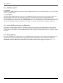
5.1. Cat5 Connection 1
Cat5 Connection 1
1 (A/ B)
2 (A+B)
1 2 3 4
Power
ADAT Clock
A
Termination
B
Carries ADAT connections 1-4 and MIDI1 data (on channel 1)
Jacks “A” and “B” are electrically paralleled.
The switch “Termination” must be set depending on the the number of cables plugged in:
1 cable = “ON”, 2 cables = “OFF”. If you use only two devices (point-to-point connection), the termination
must always remain switched on.
Wrong termination settings are, depending on the cable length, not always immediately noticeable and
the system appears to function properly. But reliability and immunity to noise is significantly decreased,
because either signals reflections occur with missing termination or transmitters get overloaded by too
many terminations.
If you're using the system in the same setup all time, you may use scotch tape to fix the push button (or
remove the push button cap) in order to prevent unwanted operation.
NOTE: Redundant connections (the connection of two units with two cables over A and B at the same time) are
not supported! This would lead to signal loops causing undefined current flow.
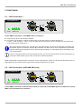
5.2. Cat5 Connection 2 (ADX-64B-PRO only)
Cat5 Connection 2
1 (A/ B)
2 (A+B)
5 6 7 8
Power
ADAT Clock
A
Termination
B
Carries ADAT connections 5-8 and wordclock data (on channel 5). If Dual-MIDI-Option is installed, the second
MIDI is also transmitted over channel 5.
7
User's Manual
6. REAR PANEL
6.1. POWER Connections
PRIMARY
POWER
SECONDARY
POWER
12V/1A
12V/1A
Connect the supplied DC adapter(s) here. The Input “SECONDARY POWER” is only present on the ADX-64BPRO with the “Redundant Power Supply” option installed.
When the “Redundant Power Supply” option is installed, two DC adapters can be plugged into “PRIMARY
POWER” and “SECONDARY POWER”. If one of them fails, the other one takes over. This is particularly useful
to make the system immune to failure of a single AC phase in 3-phase supplies.
The status of the respective supply is shown on the corresponding front panel “Power” LEDs.
Without “Redundant power supply”, the “Cat5 connection 2” bank in the ADX-64B-PRO version is supplied
from the first bank. Both LEDs are constantly lit.
Use only the supplied DC adapter, or a replacement with the indicated voltage, power, polarity and matching
connector (see 12. Specifications). The input has a reverse-polarity protection.
If the Power LED does not go on when a DC adapter is connected, check the polarity.
CH1
CH2
CH3
CH4
6.2. ADAT 1-4
Cat5 Connection 1
MIDI1
OUT
OUT
OUT
OUT
1
2
4
3
ON
IN
IN
IN
IN
1 2 3 4 5 6
IN
OUT/THRU
IN
OUT/THRU
IN
OUT/THRU
IN
OUT/THRU
IN
OUT/THRU
The transmission direction (TX or RX) must be set using the DIP switches 1-4:
Input (DIP switch in lower position = OFF): The ADAT connection is configured as input,
the received data is sent to the Cat5 cable.
The input signal is passed-through to the output alongside ("local loop-back"). You can use this
output to connect additional monitors or as wordclock source, as shown in7.2. Synchronization
over ADAT.
If you're using a daisy-chain of ADX devices, make sure that there is exactly one “Input” per ADAT connection
in the chain.
8
Output (DIP switch in upper position = ON): The ADAT connection is configured as output.
Data received from the Cat5 cable is output on the “Output” jack. The input jack is inactive.
ADX-32B / ADX-64B-PRO
OUT CH5/WC/MIDI
OUT
CH6
OUT
CH7
OUT
CH8
75Ω WC TERM
MULTI CH5 MODE
6.3. ADAT 5-8 (ADX-64B-PRO only)
Cat5 Connection 21
MIDI2
5
6
7
8
ON
IN
IN
IN
IN
OFF
WC
1 2 3 4 5 6
IN
OUT/THRU
IN
OUT/THRU
IN
OUT/THRU
IN
OUT/THRU
IN
OUT/THRU
The transmission direction (TX or RX) for channels 5-8 must be set using the DIP switches 1-4
(see 6.2. ADAT 1-4).
6.4. MIDI1
The transmission works by injecting MIDI data into the ADAT1 signal the input ADX, and extracting it at the
output ADX. This means that:
MIDI transmission works only when a valid ADAT signal is present on ADAT1
The direction of MIDI transmission is always the same as the direction of ADAT1 and is selected with the same
DIP switch.
When MIDI is set to input, unaltered MIDI data is also looped back to the “OUT/THRU” jack, allowing the
connection of additional MIDI equipment.
6.5. MIDI2 (optional in ADX-64B-PRO)
Works like MIDI1, except that ADAT5 is used for data transmission.
9
User's Manual
6.6. Wordclock (ADX-64B-PRO only)
WORDCLOCK
IN/OUT
The ADX itself do not need a clock to operate. The wordclock feature is provided for the distribution of the
wordclock signal only and is independent of the ADX operation.
The wordclock function uses Channel 5 for transmission and can operate in two different modes, selectable by
DIP switch 6:
Multi: ADAT transmission on channel 5 works as every other ADAT channel. Additionally, a wordclock derived
from the ADAT data stream is output on the WORDCLOCK jack. Note that in this mode, WORDCLOCK is
always an output, regardless of the direction setting – there's no need to feed a wordclock signal into an ADX
unit. Set WC termination (DIP switch 5) to “OFF” when using this mode.
WC: In this mode, channel 5 is used exclusively for wordclock transmission. ADAT5 and MIDI2 are inactive.
Note that for this mode, a wordclock signal must be input at one ADX device in the chain, and the direction of
the wordclock transmission must be set with DIP switch 1.
Use WC mode when compatibility with the former ADX-64A-PRO model's wordclock mode is required,
or when you don't have an ADAT data stream where the wordclock can be derived from.
Wordclock termination
When using a coaxial cable for wordclock distribution, the cable must be terminated correctly.
The ADX devices have a built-in termination resistor which can be switched on by DIP switch 5:
In most configurations, wordclock termination should be “OFF”
Switch the termination “ON” only when
- Ch5 is in WC mode and
- Ch5 set to “Input” and
- the ADX is the last device on the wordclock cable.
General requirements for wordclock termination
The wordclock master device (the sender) should be located at the end of the BNC cable chain. If there is any
termination switch or jumper, it must be “OFF”.
All devices in the middle of the cable (which are usually connected by “T”-shaped adapters must have their
wordclock termination set to “OFF”.
The last device on the chain (where the cable ends) must have the wordclock termination set to “ON”. This
can either be done by setting the appropriate switch or jumper on the device, or, if there is no such thing, by
installing a “T”-shaped BNC adapter with a 75 ohms resistor attached. Different manufacturers handle
wordclock termination differently, please refer to the manual of the respective device for instructions.
10
ADX-32B / ADX-64B-PRO
7. DEVICE SYNCHRONIZATION
7.1. General concept
For all signal sources and sinks within a digital audio system, it is required to share a common clock. This
ensures that data processing on all channels and on all devices happens at exactly the same rate. Otherwise, the
individual clocks would drift apart with time, causing the number of samples generated by one device to differ
from the number of samples expected by another – a common symptom for this are to drop-outs, crackles and
dropped samples.
To prevent this, one device (usually the mix console) is the clock master. All other devices operate in slave mode,
following the master's clock signal when generating samples.
Two ways exist to distribute the clock signal from the master to the slaves:
7.2. Synchronization over ADAT
Any ADAT signal can be used for wordclock synchronization as it carries an embedded clock signal. The master
clock device outputs ADAT streams with the master clock timing embedded, and slaves can extract the
embedded wordclock from the stream. Please refer to your equipment's manual how to set the synchronization
to ADAT. If this type of synchronization is used, no additional cabling is required.
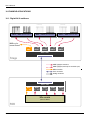
Use the "local loop-back” feature to break out additional ADAT signal outputs which can be used as
wordclock source. An example configuration using ADAT sync is shown under 10.1. Digital 24/8
multicore.
7.3. Synchronization over coaxial cable
For larger installations, it is often not convenient to use ADAT for synchronization because of its limitations:
ADAT connections cannot be split easily, and length restrictions may prevent you from reaching all devices. In
such cases, it is better to transmit the wordclock signal over a dedicated, separate connection. For this purpose, a
coaxial cable with BNC plugs is commonly used, combining long reach (>100m) with the possibility to distribute
the signal to several slave devices using “T”-shaped connectors.
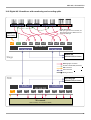
The ADX-64B-PRO's wordclock feature eliminates the need for running an extra coaxial cable beside the
Cat5. Refer to 10.2. Digital 48/16 multicore with monitoring and recording splits for an example.
You don't even need a BNC output at your master device because the coaxial wordclock signal is
extracted from ADAT data. See 6.6. Wordclock (ADX-64B-PRO only) for details.
11
User's Manual
8. CABLE RECOMMENDATIONS
8.1. Cat5 cable
Cable Quality
Cat5 cabling is commonly used, cheap, with a huge selection on the market to choose from. With the ADX
devices, any cable that meets Cat5 or higher (e.g. Cat5e, Cat6, Cat7) can be used. A higher “Cat” number cable
has no electrical advantage over a basic Cat5 type, because the parameters where the higher graded one
performs better are only important for much faster systems, like Ethernet applications.
However, if mechanical robustness is an important issue, it is recommended to use a ruggedized Cat5 cable with
Neutrik® EtherCon® connectors. Ready-to-use cable drums are available from several vendors; good value for
money, stage-proven Cat5 cable drums are made by Adam Hall, for example.
Technology
Cat5 cable consists of four twisted pairs, each made up of two single wires. One pair can carry one ADAT stream
(8 channels), yielding a total transmission capacity of 32 channels. The transmission method used on the media
is called “differential pair signaling” or “balanced transmission”. This means that each signal is transmitted over a
wire pair, where one wire carries the inverted signal of the other one. In contrast to unbalanced (groundreferenced) systems, differential signaling provides very good noise immunity, because coupled noise affects
both wires the same way and can be cancelled out at the receiver's side by subtracting one wire's signal from the
other. Additionally, EMI is greatly reduced because the electric and magnetic fields surrounding the two wires
cancel each other out.
The technology used in the ADAT Multicore Extender (RS-485) has been used for a long time, e.g. for lighting
applications (DMX) or harsh industrial environments (Profibus). The commonly used AES/EBU standard works in
a similar manner, but is, due to its relatively low data rate, only able to transmit two audio channels over one pair.
State-of-the-art technology is used in the ADAT Multicore Extenders to ensure reliable operation at the higher
data rates required by the ADAT protocol.
8.2. Toslink (Lightpipe) cable
Cable Quality
Toslink cables are generally not critical if you don't exceed their length limit of 5m (16ft). Quality cables usually
provide a tighter fit (=better latching) in the jack than cheaper ones, and may perform better on longer runs.
Technology
Plastic Optical Fiber (“POF“) cables are cheap and immune to electromagnetic interference, but are limited in
reach. Larger runs cause problems as the light pulses are attenuated too much, leading to data errors which
usually result in drop-outs or crackles. Furthermore, POFs are also very sensitive to breaks and sharp bends
which may be a problem in harsh stage environments.
12
ADX-32B / ADX-64B-PRO
9. DIGITAL SIGNAL QUALITY
9.1. Latency
Latency has – in contrast to traditional analog systems – always been a topic in digital audio technology. High
latency can lead to unwanted effects, such as phasing, hall, echo etc. and can seriously affect audio performance.
By design, other digital snake solutions (e.g. Ethernet based systems) have a relatively high propagation delay,
because audio data has to be sampled, buffered, converted, transmitted, buffered and then finally converted back
to the original format. These delays can easily add up to several tens or hundreds of milliseconds which makes
them unusable for many applications, especially for monitoring purposes.
One design goal of the ADX was to create a system with one of the lowest latencies on the market. This is
achieved by performing no conversion at all, and only minimal buffering with clock alignment.
These measures allow an excellent overall latency of less then 1µs, which is not noticeable (sound waves
travel only 0.3mm during this delay)!
9.2. Jitter
In any digital audio transmission, the clock signal picks up a certain amount of jitter (clock phase noise). Jitter can
affect audio performance (SNR) if a jittered clock is directly used for D/A or A/D conversion, and can even lead to
drop-outs or data errors if the jitter values is so high that it is impossible to determine the correct value of a bit.
For proper operation of ADAT connections, jitter is also an important issue because the duration of the “start of
frame” mark is used to calculate the sample point of the subsequent bits in the data stream. In contrast to
biphase-mark encoding used by SPDIF and AES/EBU, the ADAT signal uses NRZ encoding which allows the
double data rate, but makes it more difficult to extract the proper bit timing.
To cope with jitter, each ADAT signal is fed to a PLL circuitry which cleans the jitter by recovering proper timing
characteristics before the signal is output. The overall jitter of an ADAT signal transmitted over 100m (330ft)
Cat5 cable is only ±1.5ns typ. and is in the same range of the jitter usually introduced by a standard short fiber
optic connection. This feature allows seamless integration even with “picky” equipment (like the Presonus
Digimax FS microphone preamp, or Yamaha consoles at 48kHz) which refuses proper clock tracking when there
is a higher amount of jitter in the signal.
13
User's Manual
10. EXAMPLE APPLICATIONS
10.1. Digital 24/8 multicore
(unused)
ADC
ADC//DAC
DAC(Wordclock
(Wordclockslave)
slave)
(unused)
ADC
ADC//DAC
DAC(Wordclock
(Wordclockslave)
slave)
ADC
ADC//DAC
DAC(Wordclock
(Wordclockslave)
slave)
MIDI e.g. for
remote control
In
Out
MIDI
In Out
ADAT1
In Out
ADAT2
In Out
ADAT3
In Out
ADAT4
ADX-32B
ADX-32B
A Cat.5 B
Stage
ADAT Lightpipe connection
ADAT Lightpipe (used only for wordclock sync)
MIDI connection
Cat.5 connection
Analog connection
A Cat.5 B
ADX-32B
ADX-32B
In
MIDI
Out
ADAT1
In Out
ADAT2
In Out
ADAT3
In Out
Mix
Mixconsole
console
(Wordclock
(WordclockMaster)
Master)
FOH
14
ADAT4
In Out
ADX-32B / ADX-64B-PRO
10.2. Digital 48/16 multicore with monitoring and recording splits
ADC
ADC(Wordclock
(Wordclockslave)
slave)
ADC
ADC(Wordclock
(Wordclockslave)
slave)
ADC
ADC(Wordclock
(Wordclockslave)
slave)
DAC
DAC(Wordclock
(Wordclockslave)
slave)
* Return channel choice:
MIDI1 goes in the same direction as ADAT1, and
Wordclock is extracted from ADAT5 which must
carry a valid ADAT signal
MIDI (e.g. for
gain control)
In Out BNC W'clock In Out
output
MIDI1
ADAT1
In Out
ADAT2
Connection 1
A Cat.5 B
In Out
ADAT3
In Out
ADAT4
In Out
ADAT5
ADX-64B-PRO
ADX-64B-PRO
In Out
ADAT6
In Out
ADAT7
In Out
ADAT8
Connection 2
A Cat.5 B
Monitor mix
ADX-64B-PRO(not shown)
Stage
ADAT Lightpipe connection
75 Ohms coaxial cable (wordclock)
MIDI connection
Cat.5 connection
Analog connection
FOH
Recording split
ADX-64B-PRO(not shown)
A Cat.5 B
Connection 1
MIDI1
In Out
ADAT1
In Out
ADAT2
In Out
ADX-64B-PRO
ADX-64B-PRO
ADAT3
In Out
ADAT4
In Out
ADAT5
In Out
A Cat.5 B
Connection 2
ADAT6
In Out
ADAT7
In Out
ADAT8
In Out
Mix
Mixconsole
console
(Wordclock
(WordclockMaster,
Master,clock
clockisisembedded
embeddedininADAT5)
ADAT5)
15
User's Manual
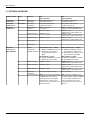
11. SETTINGS OVERVIEW
Switch location
Label
Function
Front panel
“Cat5 Conn.1”
Front panel
“Cat5 Conn. 2”
Rear panel
“Cat5 Conn.1”
Termination
2
Cat5 cable
termination
Cat5 cable
termination
ADAT1+MIDI1
direction
ADAT2 direction
ON
(upper position)
One cable connected to
“Cat5 Connection 1”
One cable connected to
“Cat5 Connection 2”
ADAT1 and MIDI1
are outputs
ADAT2 is output
3
ADAT3 direction
ADAT3 is output
4
ADAT4 direction
ADAT4 is output
5
No function
6
No function
1
ADAT5
+Wordclock
+MIDI2 direction
2
ADAT6 direction
When DIP-Switch 6 = “Multi”:
ADAT5 and MIDI2 are outputs
Wordclock jack outputs a
clock signal derived from
ADAT
When Switch 6 =”WC”:
ADAT5 and MIDI2 are inactive
Wordclock jack is output
ADAT6 is output
3
ADAT7 direction
ADAT7 is output
4
ADAT8 direction
ADAT8 is output
5
Wordclock
termination
Channel 5 mode
75 ohms termination active
When DIP-Switch 6 = “Multi”:
ADAT5 and MIDI2 are inputs,
duplicated on “THRU” jacks
Wordclock jack outputs a clock
signal derived from ADAT
When Switch 6 =”WC”:
ADAT5 and MIDI2 are inactive
Wordclock jack is input
ADAT6 is input
duplicated on “OUT/THRU” jack
ADAT7 is input
duplicated on “OUT/THRU” jack
ADAT8 is input
duplicated on “OUT/THRU” jack
No termination
Multi: Channel 5 transmits ADAT
and MIDI data. A wordclock
signal derived from the ADAT
data stream is output on the
wordclock jack, regardless of the
direction setting.
WC: Channel 5 transmits a raw
wordclock signal. ADAT and MIDI2
on this channel is disabled. The
input / output function of the
wordclock jack must be set with
switch 1.
Rear panel
“Cat5 Conn.2”
(ADX-64B-PRO)
Termination
1
6
16
OFF
(lower position)
Two cables connected to
“Cat5 Connection 1”
Two cables connected to
“Cat5 Connection 2”
ADAT1 and MIDI1 are inputs,
duplicated on “OUT/THRU” jacks
ADAT2 is input
duplicated on “OUT/THRU” jack
ADAT3 is input
duplicated on “OUT/THRU” jack
ADAT4 is input
duplicated on “OUT/THRU” jack
ADX-32B / ADX-64B-PRO
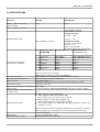
12. SPECIFICATIONS
Parameter
ADX-32B
ADX-64B-PRO
Number of ADAT connections
(audio channels)
Number of MIDI connections
4 (32)
8 (64)
1
1 (2 available on request)
Standard BNC connector
Configured as input:
“H”-level: ≥ 1.6 V
Wordclock input/output
“L”-level: ≤ 1.1V
Configured as output:
“H”-level: ≥ 3.1V an 75 Ω
“L”-level: ≤ 0.1V
Short-circuit protected
Termination (75 Ω) built-in, switchable
Standard wire color Cat5 Connection 1
Cat5 Connection 2
(TIA/EIA 568B)
(ADX-64B-PRO only)
None (available on request)
Pin
Pin assignment Cat5 cable
Jacks A+B are paralleled
1
2
3
4
5
6
7
8
orange/white
orange
green/white
blue
blue/white
green
brown/white
brown
ADAT1/MIDI1+
ADAT1/MIDI1—
ADAT2+
ADAT3+
ADAT3 —
ADAT2 —
ADAT4+
ADAT4—
ADAT 5/MIDI2/Wordclock +
ADAT 5/MIDI2/Wordclock —
ADAT 6+
ADAT 7+
ADAT 7—
ADAT 6—
ADAT 8+
ADAT 8—
All pins are short-circuit protected
ESD protection:±15 kV according to IEC 61000-4-2
Cat5 cable connectors
Neutrik EtherCon®, compatible with standard RJ45 connectors
ADAT Input/Output connectors
Optical connector F05 type (TOSLINK ®)
MIDI connectors
Standard 5-pin DIN
Twisted-Pair cable (100 ohms) according to Cat5 specification or higher
Transmission media
(e.g. Cat5e, Cat6, Cat7).
Maximum distance (end-to-end distance 330ft (100m)
of daisy-chain)
For longer distances, additional ADX-64B-PRO units can be used as repeaters
Maximum number of ADX Extenders
on a daisy-chain
32
ADAT Lightpipe ® up to 48kHz 24bit
ADAT Lightpipe ® 96kHz 24bit (S/MUX, DS)
(when using 2 optical connections per 8 channels)
ADAT Lightpipe ® 192kHz 24bit (S/MUX4, QS)
(when using 4 optical connections per 8 channels)
Supported data formats
other formats (S/PDIF up to 96kHz/24bit, AC3/Dolby Digital 5.1®, DTS ® etc.)
available on request
ADAT Latency
Jitter (measured at output)
All 4 transmission lines work completely independent of each other. This means
different sample rates, resolutions etc. can be transmitted at the same time.
<1µs (entire system)
<1µs in „local loop-back” mode
330ft (100m) Cat5 cable: ±1.5ns typ.
17
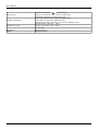
User's Manual
Power supply
Shielding / Grounding
Temperature range
Dimensions
Weight
18
12V DC 1.0 A, Polarity:
(center positive),
Plug type: ID=2.5mm, OD=Ø 5.5mm, Length=9mm
Supplied DC adapters are isolated from earth
Case is connected to power supply GND (earth-free)
Cat5 shield is connected to GND (earth-free)
Wordclock jack outer conductor is connected to GND (earth-free)
Operation: 32°F...140°F (0°C...+60°C)
Storage: 14°F...140°F (-10°C...+60°C)
19“ rack 1HE
60 mm in depth
900 grams approx.
ADX-32B / ADX-64B-PRO
13. APPENDIX
13.1.Warranty
We offer a full two (2) year warranty from the date of purchase. Within this period, we repair or exchange your
device free of charge in case of any defect.*
If you experience any problems, please contact us first. We try hard to solve your problem as soon as possible even after the warranty period.
* Not covered by the warranty are any damages resulting out of improper use, willful damage, normal wear-out
(especially of the connectors) or connection with incompatible devices (including, but not limited to, Ethernet
equipment and third-party power supplies).
13.2. Contact
Appsys ProAudio
Rolf Eichenseher
Bullingerstr. 63 / BK241
CH-8004 Zürich
Switzerland
www.appsys.ch
[email protected]
Phone: +41 22 550 05 42
Mobile: +41 76 747 07 42
13.3. Recycling
According to EU directive 2002/96/EU, electronic devices with a crossed-out dustbin may not be
disposed into normal domestic waste.
Please return the products back for environment-friendly recycling, we'll refund you the shipping fees.
13.4. About this document
ADAT® is a registered Trademark of Alesis Corp.
TOSLINK® is a registered Trademark of Toshiba Corp.
EtherCon® is a registered Trademark of Neutrik AG
All information provided here is subject to change without prior notice.
Document Revision: 1
2011-01-20
Copyright © 2010 Appsys ProAudio
Printed in Switzerland
19