1
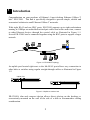
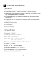
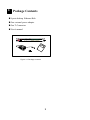
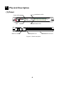
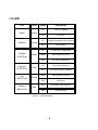
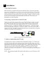
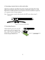
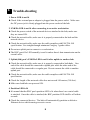
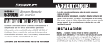
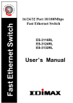
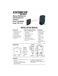
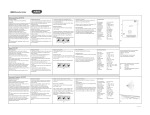
O
N A L
L
A N
PR
F E S S
I
O
9-Port Desktop
Ethernet Hub
Ethernet Hub
ER-5390S
User ’ s Manual
DIMAX
FCC COMPLIANCE STATEMENT
This equipment generates and uses radio frequency energy and if not installed
and used properly, that is, in strict accordance with the instructions provided with
the equipment, may cause interference to radio and TV reception. The
equipment has been tested and found to comply with the limits for a Class A
computing device in accordance with the specifications in Subpart B of Part 15
of FCC rules, which are designed to provide reasonable protection against such
interference in a commercial environment. However, there is no guarantee that
interference will not occur in a particular installation.
If you suspect this equipment is causing interference, turn your hub on and off
while your radio or TV is showing interference to determine the source of the
interference.
You can try to correct the interference by one or more of the following measures:
1. Reorient the receiving radio or TV antenna where this may be done safely.
2. To the extent possible, relocate the radio, TV or the other receiver away
from the equipment.
3. Plug the computer which has the equipment installed into a different power
outlet so that equipment and the receiver are on different branch circuits.
If necessary, you should consult the place of purchase or an experienced radio/
television technician for additional suggestion.
CAUTION : The phone jack cannot be connected to telephone system.
Contents
Chapter 1 Introduction ....................................1
Chapter 2 Features & Specifications ..............2
Chapter 3 Package Contents ...........................3
Chapter 4 Physical Description .......................4
Chapter 5 Installation ......................................6
Chapter 6 Trouble-shooting ............................8
11 Introduction
Congratulations on your purchase of Edimax’s 9-port desktop Ethernet 10Base-T
hub - ER-5390S. This hub is specifically designed to provide simple, reliable and
economical solution in small Ethernet 10Base-T networks.
With eight RJ-45 and one BNC ports, ER-5390S supports up to eight workstations
running at 10Mbps on unshielded twisted-pair cables and at the same time, connect
to other Ethernet devices through the coaxial cable as illustrated in Figure 1-1.
Several ER-5390S can be connected together using the BNC ports to support a larger
network.
LEO PREDATOR
MHz
60
RESETTURBO
H.D.D. LEO
A B C D POWER
LEO
Figure 1-1 ER-5390S Topology
An uplink port located right next to the 8th RJ-45 port allows easy connection to
other hubs or switches using regular straight-through cables as illustrated in Figure
1-2.
Uplink Port
OUT
Uplink
IN
8
7
6
5
4
3
2
1
OUT
Uplink
IN
8
7
6
5
4
3
2
1
Figure 1-2 Uplink to another hub
ER-5390S’s slim and compact design allows direct placing on the desktop or
conveniently mounted on the wall or the side of a desk to accommodate cabling
consideration.
1
22 Features & Specifications
(1) Features
n Comply with IEEE 802.3 10Base-2 and 10Base-T Ethernet Standards.
n Support eight RJ-45 connectors for 10Base-T connection and one 10Base-2 BNC
port for mixed media network environment.
n Built-in uplink port for easy connection to another hub using regular straightthrough cable.
n Complete sets of LEDs provide an easy diagnostic on the hub’s and individual
port’s status.
n Slim and Compact design
n Wall mountable
n Two-year warranty
(2) Specification
n Standards : IEEE 802.3
n 10Mbps Ports : RJ-45 x 8 & BNC x 1
n Hub LEDs : Power, Collision
n Port LEDs : RJ-45 -- Link/Activity, Partition
BNC - Activity, Partition
n Dimensions : 8.67 x 4.61 x 1.18 inches/220 x 117 x 30 mm
n Weight : 1.76 lb./800g
n Power : 6V DC, 0.7A external adapter
n Operating Temperature : 32-1310F (0-550C)
n Operating Humidity : 10-95% (Noncondensing)
n Emission : FCC Class A & CE Mark
2
33 Package Contents
n 9-port desktop Ethernet Hub
n One external power adapter
n One T-Connector
FE SS
O N
L
N
LA
O
I
PR
n User’s manual
DIMAX
Power
LNK/Rx
Collision
Partition
9-Port 10Mbps Ethernet Hub 1
Rx
Partition
2
3
4
5
6
7
8 BNC
Figure 3-1 Package contents
3
44 Physical Description
(1) Panel
Link/Receive LED
F E S S
L
N
LA
O N
P
O
I
R
Power LED
DIMAX
Power
Collision
LNK/Rx
Partition
9-Port 10Mbps Ethernet Hub
Collision
LED
2
3
4
5
6
7
8 BNC
Partition LED
OUT
Uplink
BNC Port
Rx
Partition
1
IN
8
7
6
5
Uplink Port
Figure 4-1 Panel description
4
4
3
2
1
RJ-45 Ports
(1) LED
LED
Color
Power
Green
Collision
Link/Act
(RJ45 Port)
Status
Description
Lit
Power is supplied
Off
No power
Lit
Collision detected in this segment
Off
No Collision
Lit
A valid link is established
Flash
Data packets received
Off
No link is established
Lit
This port is patitioned
Off
This port is working normally
Flash
Data packets received
Off
No activity
Lit
No coaxial cable attached
Off
Cable attached
Yellow
Green
Partition
(RJ45 Port)
Red
Act
(BNC Port)
Green
Partition
(BNC Port)
Red
Table 4-1 LED description
5
55 Installation
1. Operating Environment
ER-5390S must be installed and operated within the limits of specified operating
temperature and humidity (see previous section under Specifications). Do not place
objects on top of the unit. Do not obstruct any vents at the sides of the unit. Do not
position the hub near any heating source such as heater, radiator, or direct exposure
to sun. Prevent entering of water and moisture into the unit. If necessary, use
dehumidifier to reduce humidity.
2. Connecting to network devices with UTP cable
Connect one end of the network cable to any of the RJ-45 ports on the rear panel,
and connect the other end of the network cable to the RJ-45 port of the network
device. The network cables must comply with EIA/TIA 568 specifications and
minimum Category 3 standard for 10Mbps data transmission. Maximum length
between the hub and workstation is 100 meters (300ft). Once the network cable is
connected on both ends and the attached network devices are powered on, the green
LNK/Rx (Link Status) LED should be lit.
OUT
Uplink
Category 3
EIA/TIA 568
UTP Cable
IN
8
7
6
5
4
3
2
1
Network
Adapter
10/100 FAST ETHERNET CARD
FCC ID :
RTL8139
100m
Figure 5-1 Connect the hub and network device
3. Uplink to Another Hub with UTP cable
Use uplink port to connect to another hub as illustrated in Figure 1-2. Connect one
end of the network cable to the uplink port and connect the other end to any of the
regular port in the other hub (except the uplink port). Connecting cable must comply
with EIA/TIA 568 specifications and Category 3 standards to connect the hubs.
Once the network cable is connected and both hubs are powered on, the green
LNK/Rx (Link Status) LED should be lit. Do not use the uplink port and 8th port at
the same time.
NOTE : The maximum length of the uplink cable shall not exceed 100 meters (300
feet).
6
4. Connecting to network devices with coaxial cables
Attach the T-connector to the BNC port on the rear panel and connect the coaxial
cables to the both open ends of the T-connector as illustrated in Figure 5-2. If the
ER-5390S is at either end of the coaxial segment, make sure terminate the open end
of T-connector with a 50-ohm terminator.
Note : Do not connect coaxial cable directly to the BNC port without using Tconnector.
OUT
Uplink
IN
8
7
6
5
4
3
2
1
Figure 5-2 connect the coaxial cables
5. Connecting the power
OUT
Connect the DC power jack to the DC
power socket on the rear panel of the
hub. Connect the power adapter to the
power outlet. The green Power LED
on the front panel should be lit.
Uplink
IN
8
7
6
5
4
3
2
1
Figure 5-3 Connect the external
power adapter
7
66 Trouble-shooting
1. Power LED is not lit
l Check if the external power adapter is plugged into the power outlet. Make sure
the DC power jack is firmly plugged into the power socket of the hub.
2. LNK/Rx LED is not lit after connecting to an active workstation
l Check the power switch of the network devices attached to the hub; make sure
they are turned ON.
l Check the network cable; make sure it is properly connected to the hub and the
network device.
l Check the network cable; make sure the cable complies with EIA/TIA 568
specification. Use straight-through minimum Category 3 grade cables.
l Do not use uplink port to connect to a workstation.
l The BNC port’s Rx LED normally is not lit unless there’s data transmission on the
coaxial cable.
3. Uplink (8th) port’s LNK/Rx LED is not lit after uplink to another hub
l Check the network cable; make sure it is properly connected to both hubs. One
end of the cable should be connected to uplink port while the other end of the
cable should be connected to a regular port. Do not connect the cable to another
uplink port.
l Check the network cable; make sure the cable complies with EIA/TIA 568
specification.
l Check the length of the network cable does not exceed 100 meters (300 feet).
l Make sure both hubs are powered ON.
4. Partition LED is lit
l It’s normal that the BNC port’s partition LED is lit when there’s no coaxial cable
is attached. Once the cable is attached, the BNC partition LED shall be off within
seconds.
l Check the connected devices. The hub will automatically partition a defective
Ethernet device which causing excessive errors.
8
5. Collision LED is constantly flashing
l Remove all the network cables; connect the cables back one by one to isolate the
source of the collision.
l Check the network cable, inferior cable quality will result in excessive collision
and error packets.
[!] Contact your dealer if problem persist.
9