1
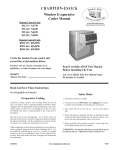
CHAMPION-ESSICK
~\ndow Units
Window Evaporative
Cooler Manual
Manual Control Units
Convertible K'tt Nor Shipped With (ookr
Available Upon Request At No Additional (ost
WC37-N37W
WC44-N44W
WC46 -N46W
WC50 -N50W
Remote Control Units
RWC35 • RN35W
RWC46 • RN46W
RWC50 • RN50W
Circle the model of your cooler and
record the serial number below.
''--./
Encierre con un circulo el 11Iodelode su
enfriador y escribe el IIllmero de serie abajo.
Read Carefully All Of This Manual
Before Installing The Unit.
Serial #
Lea Con Cuidado Todo Este Manual Antes
De Instalar La Unidad.
Numero De Serie
Read And Save These Instructions
Safety Rules
Vea el Espanol en el interior
Evaporative
Cooling
Evaporative cooling is nature's way of cooling. When air is moved
over a wet surface, water is evaporated and heat is absorbed. When
stepping out ofa swimming pool with the wind blowing, evaporative
cooling makes you feel cool, even though the air may be warm.
The human body itself is cooled primarily by the evaporation of
perspiration.
This unit works on the same principle. Air is drawn across wet
filter pads where the air is cooled by evaporation and then circulated
throughout the building. It is this combination of cooled air and the
movement of air over the skin which makes it feel cool.
Unlike refrigeration systems which recirculate the air,an evaporative
cooler continually brings in fresh air while exhausting old air. You
are completely replacing the air every 2 to 4 minutes by opening
windows or doors or a combination of both. The air is always fresh,
not stale, laden:with smoke and odors as happens with refrigerated
air conditioning .
1. Read these instructions carefully.
2. Unit must be in the Off Position and Unplugged from power
receptacle when installing or performing any maintenance.
3. This cooler will run on 120 volt A.C., 60 Hz (cycle) current
only,
4. Motor and pump are grounded and have an automatic thermal
overload switch which will "shutmotor offwhen it overheats. The
motor will restart automatically when it cools down.
5. Pump receptacle is for grounded evaporative cooler pump only_
Do not plug anything else into receptacle.
6. Do Not operate any fan with a damaged cord or plug. Discard fan
or return to an authorized service facility for examination and/or
repair.
7. Do Not run cord under carpeting. Do Not cover cord with throw
rugs, runners or similar coverings. Do Not route cord under
furniture or appliances. Arrange cord away from traffic area and
where it will not be tripped over.
&WARNING:
.~ ;l
110496-1
;:",'
To reduce the risk offire or electric shock, dn not
use this fan with any ~solid-state fan speed control device."
www.championcooler.com
1-11
Operation
Manual Control Units
• Pump setting. The rotary switch has 6 settings. The "Pump"
setting will operate the pump without the blower. For best results
turn the switch to "Pump" for a few minutes to wet the pads before
operating the fan.
• High and low cool settings. The "High Cool" and "Low Cool" settings operate both the pump and the blower. Tum the unit to "Low
Cool" when possible. This lower speed allows the air to stay longer
in the wet pads and therefore increases it's cooling elliciency.
• High and low vent settings. The "High Vent" and "Low Vent"
settings operate the blower without the pump. This is useful on
cool nights or at times when just a fan is desired.
THEN
It falls down.
CLOSE all orthe windows one inch and try step 4 again.
IF
THEN
It plasters itself to the screen.
OPEN all of the windows one inch and try step 4 again.
IF
It stays on the screen lightly.
PERFECT. You are done. Enjoy your cooler .
IF
THEN
Notes:
• When switching to Low Cool, you must rebalance your home.
Repeat step 4.
• Once you balance your home you can cool some areas more than
others by opening those windows more and closing the others by
the same amount. Repeat step 4 to make sure your home is still air
balanced.
Cooler Installation
Remote Control Units
These units may be controlled using the 3 buttons on the front panel
of the cooler or with the remote control.
• PUMP hutton. Pressing this button toggles the pump 011 and otT.
When the LED is lit, the pump is running. For best results tum
on the pump for a few minutes to wet the pads before operating
the fan. The pump must be on while operating the fan for cooling.
You may also want the pump turned offat times when just a fan is
desired.
• FAN button. Pressing this button will cycle the fan through High
Speed / Low Speed / Off. The LEO's on the front of the control
indicate wether the fan is on high speed, low speed or ofT(no LED's
lit). Note: There will be a 2 second delay betwcen a button l>ress
and the operation of the fan.
• ON/OFF button. Pressing this button while the pump or fan is Oil
willlum everything otT. Pressing it again while in the otTstate will
return the fan and pump to their previous operating settings. When
first plugging in the cooler or after power has been interrupted,
pressing the On/OfT button will start the cooler in the default state
which is with the pump on and the fan on high.
• Remote Control. To operate the cooler with the remote you must
be within 20 feet and in sight of the cooler. Aim the remote at the
front panel. The buttons 011 the remote control have the same functions as the buttons on the front panel of the cooler. The remote
uses two AAA alkaline batteries which are included. A holder for
mounting on a wall is also included with the unit.
Open Windows To Exhaust Air
An oftcn misunderstood concept of evaporative cooling is the amount
of air that should be exhausted. How much should YOliopcn your
windows'! The fact is that most people do not open their windows
enough. The following method will help you determine the amount
to open your windows.
Champion Air Balancing Method
I. Take a piece of tissue paper and cut it lengthwise into 3 equal
strips.
2. Turn your cooler on High Cool.
3. Open one window at least six inches wide in each room that you
want to cool.
4. Take the piece of tissue paper and put it lip agamst the screen ot
the open window furthest from the cooler discharge opening. Let
go of it. It will do one of three things.
2
Installing House Legs
• NOTE: If installing unit without the use of the installation kit,
omit these directions and those pertaining to Fig. 2.
• Remove two comer screws in the bottom pan (A.Fig I).
• Place the house leg bracket in the
comer of the bottom pan, using the
two top holes in the bracket (B-Fig I).
Replace the two previously removed
screws to hold the house leg bracket
in place (As shown by dotted house
leg bracket).
• Refer to the instructions "Adjust
Fig. I
house legs" below for adjusting the
house legs .
Mounting Cooler
~CA UTION: Make sure that the mounting surfacc is strong
enough to support thc operating weight of the cooler when in use.
(For operating weight, see Specification Table.)
LhCA UTION:
Never plug in cooler until installation
and unit has been tested for ri~idity .
• Lift out all removable
is enmplete
louvered sides.
• Screw chain hooks into window facing.
hooks above the neck of
the cooler a distance equal
to the width of the cooler
apart (A-Fig. 2). Hook
one hanger chain in each
D
hook and then one "S"
hook in the other end of
c
each chain.
Window
NOTE: The chain hooks
Neck
supplied with this mountH
ing kit are for usc in wood.
E
Additional anchors can be
purchased at your local
hardware store for anchoring in other types of
materials such as concrete
or brick.
Position the two chain
Fig. 2
110496-1
• Install window panel
retainers.
Place two
panel retainer strips onto
bottom of neck flange
and position to the width
of the window. Cut the
strips to fit if necessary.
These strips hold the
window fill-in panels
(Fig. 3).
L;",~
Iii
Float Rod
Bottom Panel
Retainer
Fig. 3
Position cooler in window. Position neck of
cooler so that bottom of neck flange rests on window sill and flange
(E-Fig. 2) is snug against edge of sill (H-Fig. 2). With cooler in
position, hook the US" hooks into the holes of the top pan near the
back of the cooler (B-Fig. 2).
Fill pan. Allow water to fill
to within I" of the top of the
overflow pipe and adjust float
to maintain this water level.
This can be accomplished by
bending the Ooat rod (Fig.
6).
• Break fill-in panels to fit. With cooler installed, as described
above, measure for each window fill-in panel and score with sharp
knife and straight edge guide to desired width. To break window
fill-in panels, the panel should be laid over the edge ofa straight flat
surface at the point to be broken off. Apply pressure on the edge
of the panel that extends over the edge of the surface and break off
unwanted piece.
• Install fill-in panels. Place one window 'fill-in panel on each side
of grill and into panel retainer strip at bottom of grill. Place the
other panel retainer strips onto top of neck flange and fill-in panels.
Be sure the panels are snug up against cooler neck.
• Place window behind retainer strip. Raise back of cooler so that
the window (D-Fig. 2) may be brought down behind top of panel
retainer strip (C-Fig. 2).
• Level Cooler. Adjust the chains to level the cooler.
• Adjust house legs. Pull out house legs so that the rubbcr bumpers.
rest against house siding (F-Fig. 2). Tighten screw in retaining
collar. (G-Fig. 2).
Connecting Water
• Install overflow assembly.
Remove
nut and place nipple through the hole in
the pan, with the rubber washer between
the pan and the he.1.dof the drain nipple
(Fig. 4). Screw on nut and draw uptight
against bottom of pan. Insert overflow
pipe in nipple to retain water. Overflow
pipe may be removed to drain pan whcn
necessary. A garden hose may be
screwed on the drain nipple to
drain water away from your unit.
~ ~
Overflow Pipe
~-Nipple
~-
Rubber Washer
~~BotiomPan
rt:JJ- Nut
Fig. 6
Maintenance
~WARNING: Before doing any maintenance
off and unit is unplugged.
• Connect water supply line. Install a sillcock and water valve on
faucet as shown by figure 5. Place
the nut and ferrule on the tubing
and tighten the nut until water
tight.
Water Supply
• Install tloat valve. Install
valve in the provided hole in
comer post (Fig. 6) and attach
water supply line.
Window Fill-In
Panels
be sure power is
This is for your safety •
Spring Start-Up
• Oil bearings. The blower bearings and cooler motor in this unit
should be oiled with a few drops of non-detergent 20/30 weight oil
once each year. The motor docs not need oil if it has no oil lines
for oiling. Motors that have no oil lines are lifetime oiled at the
factory and require no further oiling for the life of the unit.
I;--,CAUTlON: Do not over oil.
Over oiling can cause motor bum
3 Lb.
out, due to excessive oil getting into
I 3/4 Inches
motor winding.
• Check belt tension. A 3 lb. force
should deflect the belt 3/4 inches (see
Fig. 7). Readjust belt if needed.
~
~7.
• Clean pump. Cleaning the pump is necessary once a year at startup. For your safety, tum unit offand unplug from power receptacle .
Remove the pump from the mount slot. Remove the base of the
pump as shown in Fig. 8. Clean the pump and tum the impeller
to ensure free operation. Remove the pump spout and check for
any blockage. After cleaning,
reinstall the base onto the pump.
Press firmly to make sure it is
secure. Reattach the pump to
the mount in the cooler using
the plastic retainer to ensure that
the pump will not overturn. Do
not forget to replace the spout
and water delivery tube onto the
Fig. 8
pump outlet.
Fig. 4
Faucet
I
• Replace Pads. Aspen pads should be replaced once or twice a
season, depending upon the length of the season. At the beginning
and at mid season a clean pad is more absorbent and efficient and
will deliver substantially more cool air .
Winter Shut Down
Drain water. Always drain all of the water out of the cooler and
water supply line when not in use for prolonged periods, and particularly at the end ofthe season. Keep the water line disconnected
from both the unit and water supply so that it does not freeze.
• Cover unit. To protect the life of the finish, a cover for the unit is
suggested in extended periods of non use.
110490-1
3
• Cover grill. To help keep out cold air you can use the optional
plastic grill cover. This cover may be purchased from your local
distributor. To install the cover, line up the grill cover with the grill
so that the tabs on the cover will slide over the center section of the
grill. Slide the grill cover onto the grill. The tabs will snap into
place. To remove, just pull the grill cover straight forward away
4.
5.
from the grill.
Unplug unit from power supply during
extended
periods
of
non-use.
By following the operating, installation, and maintenance suggestions
as outlined, you can get many years of efficient and satisfactory
service from your cooler. In the event additional information is
desired, your dealer will be more than glad to assist you in every
possible way.
6.
Insert the flange of the tunnel
between the front panel and the
top pan. Line up the two larger
holes in the tunnel with the
center two holes of the top pan.
(Fig II).
Using the screws taken from the
top pan, secure the tunnel to the
unit. Do not tighten the screws,
leave them loose until the rest of
Fig. 10
the tunnel has been secured.
Line up the three holes at the
bottom of the tunnel with
Line up to the two
the holes in the front panel.
middle holes
Using the screws taken from
'
the bottom of the tunnel previously. secure the tunnel to
the front panel.
Make sure all the screws removed from the top pan are in
place and tighten all screws.
Skip this step for the RWC35
& RN35W models. Remove
the three screws (2 in models
Fig. II
WC3? & N3?Wl from each
side of the front panel as
shown in figure 12.
Metal
&.CAUTION: Make sure that
Strip
you do not remove the bottom
most screw. It holds the blower
housing in place.
To cover up the gap in the front
panel, use the two strips of metal
obtained from Customer Service.
Line up the holes in the metal strips
to the holes in the front panel and
Do Not Remove
secure them with the screws preBottom Screw
viously removed in step 8. (See
Fig. 12
Fig. 12) Install the metal strips so
that there is no gap between the
top pan and the metal strip. Ifthere is a gap, tum the metal strip
around.
..
-
Vertical Duct Conversion
7.
This window unit can be reconfigured to a vertical tunnel configuration for installation into smaller width openings. Follow the
subsequent steps if this is desired. Note: Tunnel mount strips used
to convert tunnel are not shipped with this cooler. If desired,
call Customer Service at 1-806-643-8341 to have it shipped to
you at no cost.
I. Remove the 9 screws
from the sides and bottom of the tunnel.
2. Remove the top 4 middle screws of the top
pan while holding the
tunnel in place (Fig 9).
Be careful not to drop
the tunnel, or damage
to the electric cords
could occur. You may
8.
Remove top
screws Illst. Do
_____
~_£~_~~_~~~:roPTunnel
~-~
p--
9.
Fig. 9
need to loosen other
screws in the top pan
to make it casier to remove the tunnel.
3. Rotate the tunnel 90 degrees counter-clockwise (Fig 10). Be careful as you rotate the tunnel that you don't damage or disconnect
the cords which are still connected to the controls and the front
paneL
/\
....-J-----=_ .
~..:::.
--~
--!.
NOTE: \Vhen mounting a cooler with this type of vertical tunnel
configuration, the unit should be supported by a Oat support or
stand. The installation method mentioned in the owner's manual
using chains and legs should not be used. The filler panels in
the installation kit may be used to seal off the window above the
cooler duct.
Wiring Diagrams
Remote Control
Manual Control
Switch
Black
Roo
Green
White
Q==AP.
V
"LlF
4
@===[),
110496-1
Troubleshooting
Problem
Possible Cause
Failure to
start or no air
delivery
1. No electrical power to
unit
Fuse blown
Circuit breaker
tripped
Electric cord un-
plugged or damaged
2. Belt too loose or tight
3. Motor overheated
..
Belt too tight
Blower bearings dry
4. Motor locked
Inadequate
air delivery
with cooler
running
I. Insufficient air exhaust
2. Belt too loose
3. Pads plugged
Inadequate
cooling
I. Inadequate exhaust in
house
2. Pads not wet
Pads plugged
Open spots in pads
Trough holes
clogged
Pump not working
properly
Problem
Remedy
Motor cycles
on and ofT
I. Check power
Replace fuse
Possible Cause
Remedy
I. Low voltage
2. Excessive belt tcnsion
3. Blower shaft tight or
locked
Resel breaker
4. Bearings dry
Plug in cords or
replace if damaged
2. Adjust belt tension
3. Detennine cause of
overheating
Adjust belt tension
Oil blower bearings
4. Replace motor
Noisy
housing
.
I. Open windows or
doors to increase air
flow
2. Adjust belt tension or
replace if needed
J Replace pads
I. Open windows or
doors to increase air
!low
2. Check water distributlon system
Replace pads
Repack pads
Clean trough and
unplug holes
Replace or clean
pump (Unplug
unit)
Register your product online at www.championcooler.comli
1. Bearings dry
2. Wheel rubbing blower
3. Loose parts
I. Check voltage
2. Adjust belt tension
3. Oil or replace beariogs (Unplug unit)
4. Oil bearings
1. Oil bearings
2. Inspect and realign
(Unplug unit)
3. Tighten loose parts
Excessive
humidity in
house
1. Inadequate exhaust
1. Open doors or win~
dows
Musty or
unpleasant
odor
I. Stale or stagnate water
in cooler
2. Pads mildewed or
clogged
J Pads not wetting
properly
Trough holes
clogged
Pump not working
properly
I. Drain pan and clean
pads
2. Replace pads
I. Float 31m not adjusted
properly
2. Overflowasscmbly
leaking
I. Adjust float
Water draining from
cooler
3. Check water distribution system
Clean
Replace or clean
pump (Unplug
unit)
2. Tighten nut and
overflow pipe.
••dex.phplcooler~lVarranty-registration
Limited Warranty
This walTanty is extended to the original purchaser of an evaporative cooler installed and used under nonnal conditions. It does not cover damages incurred
through accident, neglect, or abuse by the owner. We do not authorizc any person or representative to assumc for us any other or different liability in connection with this product.
,
Terms And Conditions
Of The Warranty
For Eight Years from date of purchase, we will replace the original base assembly if water leakage should occur due to rust out.
For One Year from date of purchase, we will replace any original component provided by Champion Cooler which fails due to any defect in material or fac~
tory workmanship
only.
Exclnsions From The Warranty
We arc not responsible for replacement of cooler pads. These arc disposable component,> and should be replaced periodically.
incidental or consequential damage resulting from any malfunction.
We are not responsible for any
We arc not responsible for any damage received from the use of water softeners, chemicals, descale material, plastic wrap, or if a motor ofa higher horsepower
than what is shown Oll the serial plate is used in the unit.
We arc not responsible for the cost of service calls to diagnose cause of trouble, or labor charge to repair and/or replace parts.
For limiled warranty to be valid the evaporative cooler must be maintained per the Maintenance
Section of this manual.
How To Obtain Service Under This Warranty
Contact the Dealer where you purchased the evaporative cooler. If for any reason you are not satisfied with the response from the dealer, contact the Customer
Service Department: 5800 Murray Street, Little Rock, Arkansas 72209. 1.800~643.8341. Email: [email protected].
This IimUed warranty applies to the original purchaser only.
110496-1
5
General Specifications I Especijicaciones Generales
Model No.
Modelo
Cabinet
Weight (Ib'.)
Peso (/ibras)
Dry
Seco
Dimensions
Window
(in.)
Operating
Height
Meno
A/turtl
Width
And""a
Opening
Rcq'd (in.)
Aber/ura Requerida (pulgadas)
Dimensions De La Caja (pulgadas)
Depth
Profundidad
Width
AIle/IlITll
Height
A/tura
RWC35, RN35W
113
190
301/2
31 1/2
21
213/4
143/4
WC37, N37W
125
202
337/16
28 1/8
28 1/8
213/4
143/4
WC44, N44W
137
214
341/2
34 1/8
28 1/2
213/4
143/4
WC46,N46W
152
246
341/2
34 1/8
341/8
213/4
143/4
155
249
34 1/2
341/8
34 1/8
213/4
143/4
RWC46, RN46W
WC50, N50W,
RWC50, RN50W
Motor Specifications / Especijicaciones Del Motor
Model No.
Motor Part #
HP
Speed
Velocidad
Volts
Voltios
Motor Pulley Part #
Poleo Del Motor - IV"
Drive Belt Part #
8am/a - N"
Mot/ell'
Motar - N"
CV
RWC35, RN35W
110442
1/3
2
115
110271
110226 (4L-480)
WC37, N37W
110445
1/3
2
115
110271
110211 (4L-450)
WC44,N44W
110445
1/3
2
115
110272
110215 (4L-560)
110445
1/3
2
115
110272
110215 (4L-560)
110447
1/2
2
115
110273
110215 (4L-560)
WC46, N46W
RWC46, RN46W
WCSO,N50W
RWC50, RN50W
Parts Drawing / Dibujo De Piezas
".
!~'-'~''''
16j'~l
37~ -'-',,;
I
53
38
.
6
39~~
110496-1
Replacement Parts List / Lista De Piezas De Repuesto
When ordering parl.;;,please be sure to fum ish the following infonnation on all orders. Failure to do so may delay your order. I
Al pedir piezas, incluya tada 10 ;1~formaci611 siguiente can Sl/ pedido. Ef no proporcionar toda esla informacion resul/ara en una demaro.
I.
Cooler Model No. I Mode/a de la unidad
Cooler serial number / Nl/mero de serie de la unidad
Description and part number I Descripci6n y mlmero de pieza
Date of purchase / Feeha de compra
2.
3.
4.
~o.
,"0
I.
2.
3.
4.
5.
6.
7.
8.
9.
10.
II.
12.
IJ.
14.
I;'
16.
17.
18.
19.
20.
21.
22.
23.
24.
25.
26.
27.
28.
29.
31.
33.
34.
35.
36.
37.
38.
39.
40.
41.
42.
43.
44.
45.
46.
460.
47.
48.
49.
50.
51.
52.
53.
54.
Description / Deycriocioll
Top Pan / Tapa.....
.
Bottom Pan I Ba~eDe La Caja..
..
Louvered Side Assembly / MOlltaje De Reia Lateral..
..
Water Trough, Side / Canal De Agl/a. Lateral.
Aspcn Pads, Side / Filrmx De Paja. Laferal........
Pad Rctaincr. Side I Soporte Para EI "'iltro, Lateral
Louvercd Back Assembly / Montaje De R40 Poxterior
.
Water Trough, Back / Canal De Agua, Poxterior
Aspen Pads. Baek I Fi/trm De Paja, Posterior...
.
Pad Retainer, Back / Soporle Para Et Fittro, Pm"teriur
Comer Post, With Float Hole / Poste De Esquina, Con Aglfjem Para Flotador
Comer Post, For Pump MOllnt / I'osle De Esquina. Para Montar La Bomha..
..
Front Panel/Panel
Dehmlero..........................................
.
Tunnel / mnel (Cuello Del E/!/dador)......
..
Blower Housing I Caja De La Rueda...
..
Blower Wheel /
Rlledll..
Shan, Blower Wheel I Eje De La Rueda
Bearings, Blower Wheel Shaft I Cajinetes Del Eje De La Rueda
Pulley, Blower Wheel / Polea De La Rueda
Drive Belt / Cor/'ea...
..
Motor / Molor....
..
Pulley, Motor I Po/eaDet Motor...
Motor Mount I Monlum Del Molor..
..
Motor Mount Clips I Segul'Os Para MOl/tar Motor
Float Valve I Vitll'ula Del Flotador
Pump Mount I MOl/tura De La Bomha
Pump Screen I Malia Para La Bomha
..
Pump I BOltlha
..
Pump Retainer I SujelaJor De La Bomba.
.
Tube, Water Delivery I Tuho De Aglla.
..
Water Distributor Assembly I Si.\'tel1laDe!lJisrrihllidor De Agua
Holder, Water Distributor / Soporl!' Para EI Distribllidor De Agua...
.
Over Flow Assembly I Montaie De Dl'sagiie...
House Leg Collar Assembly / Montaje De Collar De La Pala
House Leg I Pala
..
Retainers, Window Panels I GIIl/rda De Rerellcion Para Los Ponetes
Window Panels / Paneles De Relleno Para Lo Vellflllw..
.
fElectrical Cord, Motor / Cable Electrico Del Moral'
.
tWiring Harness I Cablmdo Electrico......
.
tSwitch Iinlerruptor
.
tKnob, Switch I Perilla Del Inlerruptor.......
..
.
tSwitch Box I Caja Pam Ellnrerrllplor...
.
tLockplate, Manual Unit<; / P1aea Defijacion, UnidaJes De Control Manual
tGril1 Assembly, MaUllUal Units I Rejilla Completa, Conlrol Manual.....
.
tGrill Assemhly, Remote Units / Rejilla Comp/eta, COl/trol A Di.~tancia
tL(lckplatc & Grommct, Remote Units I Pluca De{ljacirjn Con PO.l"ahi/o. Conlml A Dislo//cia
tElcctronic Control Assembly / Montaje De Control Elec/n)nico
tDre:;s Ring / Anilla Decomtivn
tRcmote Control / Mando A Dislancia..
..
**Grill Cover I Cuhierta Para La Rejilla.
.
**Blecd.OfTKit I £quipo De La Valvula De Desahogo
sMount Strips For Vertical Tunnel / Tiras De Metal Para £1 COl/ducto Vertical
Blower Brace / Soporte Para La Caia De La Rueda
.
.
WC46,N46W
RWC46, RN46W
RWC35,
IVC37,
WC44,
WC50, N50W
RN35W
N37W
N44W
RWC50, RN50W
322175-001
222903-001
222905-00 I
220901-003
222175.002
222904-003
222903-006
220902-002
324006-107 (2) 324006-303 (3) 324006-106 (2) 324007-205 (3)
.. 226004-001 (2) 226003-001 (3) 226003-001 (2) 226003-002 (3)
.. 110084 (2)
110091 (3)
110094(2)
110098(3)
3PW-16 (6)
3PW-3 (9)
3PW-3 (6)
3PW-5 (9)
324006-108
See/Vea #3
324007-205
ScelVea #3
226004-002
226003-002
110083
110098
3PW-15
3PW-5 (3)
224003-022
224018-002
224003-032
224003-032
224018-001
224003-047
224003-046
224003-047
224103-006
224106-007
224175-001
224105-004
322120-001
322120-001
322120-001
322120-001
324104-009
324175-002
324103-007
324105-006
110765
15BW
12BW
16BW
110182
110179
110182
110183
110351 (2)
110351-001 (2) 110351 (2)
110351 (2)
110274
110270
110275
110275
110211
110226
110215
110215
,
110445'
110442*
110445'
,
110271
110272
.
110271
314003,024
314003-025
314003-001
320175-001
314005-001
314005-001
314005-001 .
314005-001
FL-C
FL-C
FL-C
FL-C
222175-005
218001-031
218001-031
218001-031
281001-001
281001-001
281001-001
281001-001
110436
110436
110436
110436
110714
110714
110714
110714
310716
310716
310716
310716
30-2
30-15
30-3
30-10
110574 (3)
.
110574 (3)
110574 (6)
30A-I
..
30A-1
30A-I
30A-I
3HL-1 (2)
.. 3HL-3 (2)
3HL-I (2)
3HL-I (2)
310811 (2)
310811 (2)
310811 (~)
310811 (2)
110599 (4)
110599 (4)
110599 (4)
110599 (4)
110603 (2)
110603 (2)
110603 (2)
110603 (2)
110364j
110364
110372j
1I0375j
.
110375j
110375
1I0425j
1I0425j
110425
1I0839-006j
110839-006
l10839-006j
.
222006-001
222006-00 I t
222006-00 I j
222007-00 Ij
222007-001
222oo7-o0lj
110839-1
110839-lj
.
110839-lj
I 10839-2t
110&39-21
110839-2!
322007-0041
322007-004t
322007-0041
l10400!
110400t
1104001
1104031
.
110403t
1104031
l10401-lj
110401.1 t
110401-11
IIOR29**
110829"
110829**
110829"
310586**
310586**
310586"
310586"
370804~
322008-0011
322008-0011
322008-00 I 1
222175-003 (2)
* See motor specificationlable. I Vea la tabla de eSfJecificaciones del molar.
** Optional accessories. Must be purchased separately. I Accesorios opcionales. Debe comprorlos por separaJo.~.
t For Manual Control unilli. I Para las unidades de control manual.
t For Remote Control units. I Para las IInidades de contmt a di.~/ancia.
S Not included with unil. Call 1.800-643-8341 to obtain this part at no additional cost. / No incluido can ta unidad. Llame 1-800-643~8341 para ohtener csta parte
sin coste adicionol.
NOTE: Standard hardware items may be purchased from your local hartlwllre store.
1VflfJgt:tf'u'os
de usn cnrriente pueden comprarse en ta{erJ'f!Ieria de su localidad.
7
Operacion
Lea y Conserve Estas.Instrucciones
Para Las Unidades De Control Manual
Reglas De Seguridad
I. Lea las instruccioncs con cuidado.
2. La unidad debe estar Apagada y Desconcctada de 1aelectricidad
cuando sc instale 0 haga cualquicr mantcnimiento.
3. Su cnfriador funciona s610 con corriente altema de 120 vatti~g,
60 Hz. (ciclos).
4. El motor y Ia bomba estfm concctados con la tierra, y se apagaran
automaticamcnte en caso de sobrecalentamicnto. Los motores
volverfm a fUl1cionar cuando se enfrian.
5. Enchufe una bomba del enfriador evaporativo solamente y nada
mas al receptacula de la bomba.
6. No haga a funcionar ningim ventilador con el cable
danado. Deseche el ventilador
0
0
el enchufe
lIevelo a una instalaci6n de
scrvicio autorizada para revisarlo y/o repararlo.
7. No pase el cable dcbajo de alfombras. No cubra cI cable can tapetes, alfombras 0 coberturas similaros. No pase el cable debajo
de los muebles 0 los aparatos. Coloquc el cable Icjos del area de
tcifico y donde no se puede tropezar con el.
&A:DVERTENCIA:
Para reducir el riesgo de inccndio 0 toques
eh~ctricos, no use este ventilador con ningim "dispositivo de estado
solido para controlar la velocidad del venlilador."
Enfriamiento Por Evaporacion
EI enfriamiento por medio de evaporacion es la manera de la naturaleza de refrcscarse. Cuando eI aire se mueve sobre una superficie
mojada, se evapora el agua y se absorbe el calor. Al salir de una
piscina can 01 viento que sapia listed se siente fresco, aunque eI
aire puede ser caliente. El cuerpo humano Sl mismo es refrescado
pnncipahnente por la evaporacion del sudor.
Este enfriador funciona usando el mismo principio. EI aire se traza
a traves de los filtros mojados donde el aire sc enfria par media de
evaporacion y dcspues circula a traves del cdificio. Se haec frio de
la sensacion cuando tiene esta combinacion del aire enfriado y del
movimicnto del airc sobre la pic I.
A difercncia de los acondicionadores de aire que recirculan el aire,
un enfriador evaporativo trae continuamente por dentro el aire fresco
mientras agota eI aire viejo. Se reemplaza completamente el aire cada
2 a 4 minutos, abriendo las ventanas 0 las puertas 0 una combinaclon
de ambas. EI aire es sicmpre fresco, no cs viciado, cargado de humo
y olores como ocurre con los sistemas de aire acondicionado a base
de refrigeracion.
• La posicion PUMP. EI interruptor tiene seis posicioncs. Ajuste
el intenuptor a la posicion PUMP (bomba) para poner en mareha
la bomba sin el ventilador. Para mejor resultauo ponga en marcha
la bomba par lInos ClIantos minutos para mojar los filtros antes de
poner en marcha el ventilador.
• Los posiciones HIGH COOLy LOW COOL. Ajuste eI intemlplor
a la posicion HIGH COOL 0 LOW COOL para poner en marcha el
ventilador a una alta 0 baja velocidad junto con Ia bomba. Ajuste
el interruptor a Ia posicion LOW COOL cuando posible. Esta baja
velocidad del ventilador pennite que el aire sc queda mas de largo
en los filtros mojados y de tal modo produce un aire ma ••fresco.
Los posiciones HIGH \'E~T Y LO\VVENT. Ajuste el interruptor
a la posicion HIGH VEST (alta) 0 LOW VENT (baja) para poner
en marcha el ventilador a una alta 0 baja velocidad sin la bomba.
Este es Iltil en noches freseas 0 cuando sc desea un ventilador
solamente.
Para Las Unidades De Control A Distancia
Estas unidades pucden ser controladas con los tres botones en la rejilla
por delante del enfriador 0 con el mando a distancia.
• El BolOn PUMP. Al presionar este baton pondni en marcha y
apagara la bomba. Cuando esta iluminada la luz LED, la bomba
esm en marcha. Para mejor resultado ponga en marcha la bomba
por unos cuantos minutos para mojar los filtros antes de poner en
marcha el ventilador. Para tener aire fresco, debe poner en marcha
la bomba mientras e1 ventilador esta en marcha. Se puede apagar
la bomba cuando se desea un ventilador solamente.
• EI Boton FAN. Estc boton controla el ventilador. AI presionar
este boton cuando eI ventilador esta apagado pondnl en marcha el
ventilador a alta vcloeidad. La segunda prensa pondn'i en marcha
a baja velocidad, y la prensa siguiente apagan'i el ventilador. Hay
luecs LED por el frente del control que indica en cual estado este
e1 ventilador - alta velocidad, baja veloeidad, 0 apagado (ninguna
luz LED iluminada). Nota: Habra un retardo de dos segundos
entre una prcnsa del boton y la operaci6n del ventilador.
• EI Boton ON/OFF. Al presionar este boton mientras esta encendido el vcntilador 0 la bomba apagara todo. AI presionarlo otm
vez mientras este apagado volveni cI ventilador y la bomba a sus
estados de funcionamicnto antedores.
Cuanda pnmero enchufc cI
enfriador 0 dcspues de que la electricidad se haya interrumpido,
presionando el boton On/Off encendera el enfriador a su cstado por
defccto 10 cual esta con la bomba encendido y el ventilador en el
estado de alta ve1ocidad.
• EI Mando A l>istancia. Al funcionar el enfriador con el mando a
distancia, debe estarno mas de 20 pesados a distancia y en la vista
del enfriador. Apunte e1 mando a distancia al.frente del enfriador.
Los hotlmes del mando a distancia tiene las mismas funciones que
los botones en el frente del enfriador. EI mando a distancia utiliza
dos acumuladores alcalinos incluidos de "AAA". Un sostenedor
para montar en la pared tambien se incluye con la unidad.
110496-1
;,Cuanto Debe Abrir Las Ventanas?
Un concepto a menudo entendido mal de enfriamiento por evaporacion es la cantidad de aire que debe seT agotada. Cminto debe usted
abrir sus ventanas? EI hecho es que la mayorfa de 1agente no abre
sus ventanas bastantc. El metodo siguiente Ie ayudarn.
EI Metodo De Champion De Equilibrar EI Aire
1. Tome un pedazo de papel de scda y cortelo a 10 largo en 3 tiTas
iguales.
2. Ponga
marcha a su enfriador a "High Coo)".
3. Abra una ventana por 10 menos seis pulgadas de ancho en carla
sitio que usted dcsee refrescar.
4. Tome un pcdazo de papel de seda y pongalo contra la pantalla de
la vcntana abierta mas lejos de la apertura del cnfriador. Sueltalo
en
al papel de seda. Hant una de tres cosas:
SI:
ENTONCES:
SI:
ENTONCES:
SI:
ENTONCES:
Se caiga.
CIERRE todas las ventanas una pulgada e intcnte
el paso 4 otra vez.
Se queda contra la pantalla can fuerza.
ABRA todas las ventanas una pulgada e intente el
paso 4 otra vez.
Se queda ligeramente contra la pantalla.
PERFECTO. Se ha acabado. Goce del aire refrescante.
NOTAS:
• AI poner el enfriador a "Low Cool", usted debe reequilibrar el aire
• Quite todas las rcjas de los costados.
• Fije los ganchos en la pared. Ponga los dos ganchos para la cadena
arriba del cuello del enfriador, separados por una distancia equivalente al ancho de la unidad
(A-fig. 2). Enganche una
cadena en cada gancho y
luego enganche un gancho "5" en cada cadena.
NOTA: Los ganchos que
vienen can esta unidad
tienen rosea de tornillo
para madera y son para
uso en paredes de madera.
Las paredes de concreto 0
ladrillo requieren el uso
de tuercas mariposas de
suficiente fuerza 0 andas
con gauchos de acoplamientos.
D
"
c
Cuello
H
E
Fig. 2
Panelc;; De
• Instale las guardas de
retencion. Coloque dos
guardas de retencion
en la parte inferior de
la pestana del cuello y
ajustelas al ancho de
la ventana.
Corte las
guardas si es necessario.
Estas sujetan a los pane-
les de relleno (fig. 3).
Relleno
Guarda Dc Retenci6n Inferior
Fig. 3
de su hogar. Repita el paso 4.
• AI equilibrar el aire de su hogar listed puedc refrescar algunas areas
mas que otras abriendo esas ventanas mas y cerrando las otras por
la misma cantidad. Repita el paso 4. Ascgurarse de que el aire de
su hogar sea equilibrado.
• Coloque el enfriador en la ventaoa. eoloque el cuello del cnfriador dentro de la ventana para que 1aparte inferior de la pestana
del cuello se asiente en la repisa de la ventana y la pestaiia (E-fig.
2) se ajustc contra eI borde de la rcpisa (H-fig. 2). Con Ia unidad
situado en la ventana, enganche los ganchos "S" en los agujeros
encontrado en la esquina trasera superior del enfriador (B-fig. 2).
Instalaci6n
• Rompa los panelcs de relleRo. Con c1enfriador instalado segun el
metodo de arriba, mida cI aucho requerido para cada panel. Marque
el panel con un cuchillo filoso y una regia al ancho correcto. Apoye
el panel en el borde de una superficie lisa y plana y presione sobre
la parte del panel que se extienda sobre el borde de la superficie,
para que se dcsprenda la parte sobrante .
Instalar Las Patas
• NOTA: Si instale la unidad sin el uso del equipo de instalaci6n,
omite las direcciones siguientes y las de la figllra 2.
• Quite los tomillos de la esquina de la
bandeja (A-fig. I).
• Instale los paneles de relleno. eoloque un panel de reHeno a cada
Iado de la rejilla y dentro de la banda de retencion situada en la
parte inferior de la rcjilla. Coloque las otras guardas de retencion
en la parte superior de la pestana del cuello y los pane1es de relleno. Compruebe que los pancles qucdcn bien ajustados contra cl
cuello .
• Coloque la mensula en la esquina de
la bandeja usando los dos agujeros de
la parle superior de la mensula (B-fig.
I) Y los dos tomillos que antes habia
quitado.
• Coloque la mensula del otro lado de
la misma manera.
• Yea la instrucci6n abajo de "Ajuste
las patas" para ajustar las patas.
Fig. I
• Coloque la ventana detras de la guarda de retencion. Levante
la parte trasera del enfriador para que la ventana (D-fig. 2) pueda
bajarse y quedar detnis de la parte superior de la guarda de retencion
(C-fig. 2).
Instalar EI Enfriador
&RECAUCION:
La superficie en que ha de colocarse el
enfriador debera aguantar cl peso completo de la unidad cuando
esta esta en funcionamiento.
(Para saber este peso, yea la tabla
• Nivele el enfriador.
nivel.
de especificaciones.)
• Ajuste las patas. Saque las palas (F-fig. 2) para que los topes de
Ajuste las cadenas hasta que el enfriador este
hule descanscn contra el costado de la pared. Apriete el tornillo
ibPRECA UCION:
No conecte el enfriador
talacion cste completa y se haya comprobado
mismo.
110496-1
hasta que la insla estabilidad del
del collar (G-fig. 2).
9
Conectar EI Agua
• Instale el montajc de desagiie. Quite la tuerca y pase la boquilla
porel agujcro de la bandeja, colocando la arandela de goma entre la
bandeja y 1acabeza de la boquilla (fig. 4). Coloque la tuefca en 13
boquilla y atomHlela hasta que quede
apretada contra 13parte inferior de la
~ - Tubo De Dcsagiie
bandeja. Inserte el tubo de desagGe
en la boquilla para retener el agu3.
Boquilla Roseada
EI tubo de desagUe sc puede quitar
0- Arandcla De Goma
para desaguar el agua de la bandeja
Bandeja
rff/...::2)-
cuande sea necesario.
Se puede
0-
conectar una manguera de jardin a la
boquilla para desaguar el agua hacia
otTa parte.
Tucrca
Fig. 4
• Conecte el tubo de abastecimiento de agua. Instale la Have
de paso y la valvula de agua en el
grifo de agua segun indica la figura
5. Coloque Ia tuerca y la ferula en
el tubo y apricle bien la merca para
impedir que gotee c1 agua.
• fustale la valvula del flotador.
Instale la valvula en el agujero
que se encuentra en el poste
de esquina (fig. 6) Y conecte
el tubo de agua.
• L1ene la bandeja con agua.
Permita que se Hene la bandeja con agua hasta una altura
de una pulgada por debajo del
borde superior de la bandeja
y ajuste eI flotador para que
manlenga este nivel. Esto
se puede lograr torciendo la
varilla para arriba 0 para abajo
(hg.
';;~"
it
Tubo Dc Abastec.
imiento De Agua
Fig. 6
oJ.
• Limpie la bomba.
Es necesario limpiar la bomba una vez al
principio de cada ano. Por su propia seguridad, apague Ia unidad
y desconectela de la electricidad. Quite el sujetador de plastico de
la montura y jale la bomba, deslizandola hacia usted. Quite la base
de la bomba segun se muestra
en la figura 7. Limpie la bomQuite
ba. De Ie vuelta a la heliee
La Base
para verificar que se muevc
libremente. Quite e1pico de la
bomba y yea si esta ohstruido.
Despues de limpiar, reinstale
helice
la base en la bomba. Presiona
firmemente para asegurarse
Fig. 7
de que es segura. Vue Iva a
colocar la bomba en la unidad
y fijela en su montura con e1 sujetador de plastico. Esto impcdira
que sc caiga la bomba al agua.lo que dailaria el motor. No se olvide
de volver a conectar el tubo de agua a la bomba.
• Lubrique los cojinetes. Los cojinetes de la meda y el motor del
ventilador deben ser lubricados usando unas gotas de un aeeite
no dctergente de densidad 20/30 una vez al ano. No obstante, los
motores sin tuberias para aceitc no necesitan ser lubricados. Estos
motores son lubricados en la fabrica de por vida y no requieren
nunca ninguna lubricaci6n.
MRECAUC10N: No lubrique demas. EI agregar demasiado
aceite puede ocasionar que se queme el motor, a causa del aeeite
entrando al interior del motof.
3 Libras
• Compruebe la tension de la correa. Una fuerza de 3 libras debe
desviar la correa 3/4 pulgadas
(vease fig. 8). Ajuste Ia correa si
es necesaflo.
t
3/4 Pulgadas
~
~8
Preparar La Unidad Para EI Invierno
• Drene el agua. Drene sicmpre toda eI agua de la unidad y del tubo
de abastecimiento de agua cuando no use el enfriador durante periodos prolongados, especialmente al fin de la temporada. EI tubo
debe quedarse desconectado del enfriador y del abastecimiento de
agua para que no 10conge Ie.
Mantenimiento
&ADVERTENCIA:
Antes de hacer cualquier mantenimiento,
compruebe que la unidad este apagada y desconectada
de la
electricidad.
Esto es pur su seguridad.
Puesta En Marcha En La Primavera
• Camhie los filtros. Debe cambiar los filtros de paja una 0 dos veces
durante eada temporada, segun la duracion de esla. Al principio y
a mediados de Ia temporada, un filtro Iimpio es mas absorbente y
eficientc y producira un mayor volumen de aire frio.
• Cubra la unidad. Para proteger y alargar la vida uti! del acabado,
se sugiere cubrif el enfriador durante periodos largos cuando no
sea utilizado.
Desconecte la unidad de la electricidad
durante periodos extendidos.
cuando no sea utilizada
• Cobra la rejilla. Para ayudar a guardar el aire frio de entrar en la
casa, usted puede utilizar la cubierta pIastica opcional. Se puede
comprar la cubierta de su distribuidor local. Al instalar la cubierta,
alince la cubicrta con la rejilla de modo que los clips de la cubierta se
deslizanln sobre la seccion de centro de la rejilla. Deslice la cubicrta
sobre la rejilla. Los clips de la cubierta se encajaran a presion hacia
lugar. Para qui tar, de un tiron con cuidado a la cubierta, quitindola
derecho adelante de la rejilla.
Si usted sigue esta<;sugerencias en cuanto a instalacion, operacion y
mantenimiento, podra disfrutar de muchos anos de scrvicio eficiente
y satisfactorio de este enfriadof. Si dcsea mas informacion, su concesionario tendni mucho gusto en ayudarle con respecto a cualquicr
duda 0 pregunta.
10
110496-1
\.....J
Conversion Al Conducto Vertical
Esta unidad sc puede configurar de nuevo a una configuraci6n con el
conducto vertical para la instalaci6n en una abertura mas pequei'ia de
la anchura. Siga los pasas subsecuentcs si se dcsea esta configuracion.
Nota: Los tiras de metal usarlos para convertir el tunel no sc eovia
con esta unidad. Si desea, se puede lIamar el servicio de c1iente a
1-800-643-8341 para ohteoerlos sin coste adidonal.
I. Quite los 9 tomillos de ambos ladas y del fondo del conducto.
2. Quite los 4 lamillas
medias de la tapa
mientras que soporte
eI conducto en lugar.
(Vease fig. 9). Tcnga
cuidado de no dejar
caCf el conducto
0
los danos a los cables elcctricos podrian
ocurrir.
Puede nccesitar aflojar alros
lamillas
en la tapa
para hacerla Imis faei!
Quite Los Tornillos
Superiorcs AI Ultima
Vez. No Deja Cacr
IIlt-J-~.:
Alinec A 1.os Dos
Agujcros Mcclios
-<
-'
.
c'\ .
-::~.,
~~
8.--
6. Alinee los tres aglljeros en eI
fondo del conducto con los
agujeros en el panel delante~
roo Con los tomillos quitados
del condllcto previa mente,
asegure el conducto al panel
delantero.
-~
Fig. II
..-~ ..".~
'. _ ...__ . EI Condueto.
--=:;':o::i.~
7. Asegurese de que todos los tomillos quitados previamcnte de la
tapa sea en Ingar y apnete todos los tomillos.
8. Omite este paso para modelos RWC35 y RN35W. Quite los tres
tomillos (2 en los modelos we37 y N37W) de cada lado del panel
delantero segun 10 demostrado en Ia figura 12.
6PRECAUClON: Asegurese de qne no quite el tornillo mas
bajo. li:ste tornillo soporta la caja del ventilador.
~~
Fig. 9
Tim De
qui tar el conducto.
9. Para cubrir el abertura en el panel
delantero, utilice las dos tiras de
metal obtenidas del servicio de
chente. Alinee los agujeros en
las tiras de metal a los agujeros
en eI panel delantero y asegurelos
con los tomillos quitados previamente en eI paso 8. (Vease fig.
12.) Instale las tiras de metal de
modo que no haya abertura entre
la tapa y la tira de metal. Si hay
una abertura, de vuelta a la tira de
metal alrededor.
3. Dc vuelta al conducto 90 grados a Ia izquierda (vease Fig
10). Tenga cuidado cuando
da vuelta al conducto que no
desconecta ni hace dano a los
cables electricos que todavia
estan conectadas con eI control
y el panel dclantero.
4.
5. Con los tornillos quitados
previamente de la tapa, ascgme eI conducto a la unidad.
No apricte los tomillos. Dcjenlos flojos hasta que el resto
del conducto se ha asegurado.
Inserte eI rebordc del cOllducto
entre eI panel delantero y la
tapa. Alinee los dos agujeros
mas grandes en el conducto
con los dos agujcros de centro
de 1atapa. (Yease Fig 11).
Fig. 10
(: ~IYr
~'-,.;..,.
,'I
No Qmte El
Tornillo Mas
Bajo
/
Metal
t
Fig. 12
NOTA: AI montar un enfriador con este tipo de configuracion
con el conducto vertical, debe soportar la unidad con un soporte
o plataforma plana. EI metodo de instalacion men cion ado en este
manual usando cadenas y las patas no debe ser utilizado. Los
paneles del rellcno en el kit de instalacion se puede utilizar para
aislar la ventana arriba del conducto del cnfriador.
Esquemas Del Cableado
Control A Distancia
Control Manual
Tornillo
Motor Uc
\" La Rueda
Alto
Uajo
TiCITa
Comlln
Nc ro
Ro'o
Verde
Blanco
Enehufe
'"
Interruptor
""
fr
Dc Tierra
Ne ro
Ro'o
PI",D,
Fijaeion Con
Pasahilo
\
•
Verde
Blanco
\
110496-1
11
La Localizacion De Averias
No arranca
no sale aire
0
I. No IIcga corriente
Fusible fundido
Cortacircuito desactivado
Cable clcctrico
dai'iado
2. Correa mllY Raja 0
apretada
3. Motor recalentado
Correa fiUY apretada
Cojinetes de la rueda
estan seeos
4. Motor parado
Sale poco
aire cuando
la unidad csta
funcionando
Enfriamiento
inadecuado
Remedio
Problema
I. Revise la comente
Cambie el fusible
Restableccr el
cortacircuito
Reemplace el cable
Motor se apaga
y sc cnciende
Causa Posible
Problema
I. Insufieientc abertura
para que salga el aire
2. Poca Icnsion en la
correa
3. Filtros obstmidas
I. EI agotamiento del aire
esinadecuado
2. Los filtros no estan
mojados
Filtros obstmidos
Filtros agujereados
Agujeros de los
canales obslruidos
Bomba no funciona
correa
J. Determine la caUf>a
Ajuste la tension de
la correa
Lubrique los cojinelos
4. Cambie el motor
I. Abra las vcntanas 0 las
puertas para aumentar
cl fluio de aire
2. Ajusle la tension 0
cambie la correa
3. Cambie los filtros
I. Abra mas las ventanas
o puertas
2. Revise la distribuci6n
de agua
Cambie los filtros
Acomotlc la paja en
el filtro
Limpiclos
Cambiela 0 !impiela
(Desconecte la
unidad)
I. Voltajc deficiente
2. Demasiada tension en
la correa
3. Eje del ventilador
arorada
4. Cojinetes secas
2. Ajuste la tension de la
Haec Ruido
Remedio
Causa Posible
Cojinetcs seCDS
Rueda roza contra caja
de la rueda
3. Partes sueltas
I.
,
I. Compruebe el voltajc
correa
3. Lubrique
0 cambie los
cojinctes (Dcsconecte
la unidad)
4. Lubriquc los cojinetes
I. Lubrique los cojinetes
2. Inspeccione y alincc
(Desconccte
la unidad)
J. Aprictelas
Demasiada
humedad en la
casa
I. Insuficiente salida de
aire
I. Abra las puertas
ventanas
Olora cncerrado,olor
dcsagradablc
I. Agua cstancado en la
unidad
2. Los filtros tienen moho
o son obstruidos.
3. Los filtros son secas
I. Desagiie y limpie los
filtros
2. Cambie los filtros
I. EI flotador no se ajusta
corrcctamenle
2. El montaje de desagiie
se esta escapando
0
las
3. Revise la distribucion
de agua
Limpielos
Agujeros del canal
tapados
Bomba no trabaja
adecuada
El agua esta
drenando del
enmador.
Rcemplacc 0 Iimpic
la bomba (Desconeete la unidad)
I. Ajusle el flotador
2. Apriete la tuerca y el
tubo de desague
Registre su producto en linea a: www.championcooler.com/index.php/cooler-warranty-registration
Garantla Limitada
La presente garantia se extiende al comprador original de un cnfriador evaporativo instalado y utilizado bajo condiciones nonnales. No cubre danos ocurridos
por accidente, descuido 0 abuso por parte del propictario. No autorizamos que ninguna olra persona 0 representante asuma por nosotros cualquier otra 0 diferente rcsponsabilidad
en relacion con este producto.
Terminos y Condiciones De La Garantia
Durante Ocho Mios a partir de la fcclla de compra, nosotros reemplazaremos
Durante Un Ano a partir de la fccha de compra, reemplazaremos
defecto de material
0
la base original del enfriador en caso de que goteara agua debido a oxidaci6n.
cualquier componente original proporcionado
por Champion Cooler que falle debido a eualquicr
mano de obra en la fiibrica solamente.
Exclusiones De La Garantia
No somos responsables por reemplazar los filtros del enfriador. Estos son componentes dcsechables y debencambiarse
por danos que resulten a consecucncia de alguna falla de funcionamicnto.
pcriOdicamente.
No somos responsables por cualquier dano producido por cI usa de suavizadores de agua, productos quimicos, materiales desincrustantes,
o si se lisa en esta unidad Ull motor de mayor potencia de la que sc indica en la placa de numero de serie.
No somos responsables
envolturas de pliistico,
No somos respollsables por eI costo del servicio para diagnosticar la causa del problema ni por la mano de obra necesaria para reparar ylo reemplazar piezas.
Para que la garaotia limitada sea valida, se debe mantener el enfriador evaporativo segun la scccion de Mantenimiento
en cste manual.
Como Obtener Servicio Bajo Esta Garantia
Pongase en contaclo con el Concesionario que Ie vendio el enfriador. Si por alguna razon usted no queda satisfecho con la respuesta porparte del Concesionario,
comuniqucse con eI departamento de scrvicio al c1iente: 5800 Murray Street, Little Rock, Arkansas 72209. 1-800-643.8341. [email protected].
Esta garanda limitada se aplica al comprador original solamente.
12
V
2. Ajustc la tension de la
110496-1
\.-I
-