1
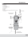
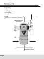
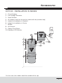
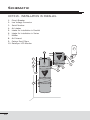
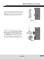
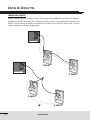
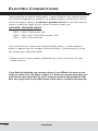
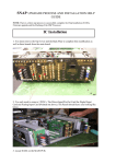
OWNER’S MANUAL
FOR HOUSEHOLD USE ONLY
Please read this document carefully before installing and/or
using your vacuum cleaning system.
SERIAL NO : _________________________________________________
AUSTRALIA
IMPORTANT SAFETY INSTRUCTIONS
When using an electrical appliance, basic precautions should always be followed, including the following.
Read all instructions before using this appliance.
WARNING – To reduce the risk of fire, electric shock, or injury:
1. Do not leave appliance unattended when plugged in. Unplug from outlet when
not in use and before maintenance.
2. Do not use outdoors or on wet surfaces.
3. Do not allow to be used as a toy. Close attention is necessary when used
by or near children or disabled persons. This appliance is not intended for
use by persons (including children) with reduced physical, sensory or mental
capabilities, or lack of experience and knowledge, unless they have been given
supervision or instruction concerning the use of the appliance by a person
responsible for their safety.
4. Cleaning and user maintenance shall not be made by children without
supervision.
5. Use only as described in this manual. Use only manufacturer’s recommended
attachments.
6. Do not use with damaged cord or plug. If appliance is not working as it should,
has been dropped, damaged, left outdoors, or dropped into water, return it to
a Cyclo Vac service center.
7. Do not pull or carry by cord, use cord as a handle, close a door on cord, or pull
cord around sharp edges or corners. Keep cord away from heated surfaces.
8. Do not unplug by pulling on cord. To unplug, grasp the plug, not the cord.
9. Do not handle plug or appliance with wet hands.
10. Do not put any objects into openings. Do not use with any opening blocked;
keep free of dust, lint, hair, and anything that may reduce air flow.
11. Keep hair, loose clothing, fingers, and all parts of body away from openings
and moving parts.
12. Do not vacuum anything that is burning or smoking, such as cigarettes,
matches, or hot ashes.
13. Do not use without dust bag and/or filter(s) in place.
14. Turn off all controls before unplugging.
15. Use extra care when cleaning stairs.
16. Do not use to pick up flammable or combustible liquids such as gasoline or
use in areas where they may be present.
17. Connect to a properly grounded outlet only. See Grounding Instructions.
KEEP THESE INSTRUCTIONS
3
Table of Contents
Preface
Schematic – H series
Schematic – HX series
Schematic – HX7515 model
6
7
8
9
INSTALLATION
Unit installation
Dos and Don’ts - inlet installation
Muffler installation
Electric connections
Grounding instructions
Low voltage connections
11
12
13
14
15
16
OPERATING INSTRUCTIONS
Hose hook-up & inlets
Progressive start
Automatic stop
DataSync monitor
DataSync hose
17
18
18
19
20
MAINTENANCE
Motor
Carbon dust filter
Dust receptacle
H & HX Series - Hybrid filtration
21
21
21
22
TROUBLESHOOTING
General Information
Decrease in suction strength
Vacuum will not start
Vacuum will not stop
WARRANTY INFORMATION
Warranty Information
WEEE Directive
24
25
27
28
29
31
Preface
Your new Cyclo Vac central vacuum system was designed and manufactured in
Blainville, Quebec, by the largest central vacuum cleaner manufacturer in Canada.
With over fifty years of experience in the field, we provide a high-quality, state-ofthe-art product, and guarantee your complete satisfaction. Our extensive network
of qualified professionals ensures first quality service near you. Contact us for
the location of the Cyclo Vac authorized dealer in your area, or visit our website:
www.cyclovac.com.au.
6
Schematic
H SERIES
1.
2.
3.
4.
5.
6.
7.
Circuit breaker
Low Voltage Connector
Serial Number
Air Intake
Muffler
Carbon Dust Filter (except 215, 615 & 715 models)
Air Exhaust
min. 30 cm (12")
With muffler turned down,
min. 30 cm (12")
6
5
1
2
3
7
4
min. 30 cm (12")
min. 30 cm (12")
min. 30 cm (12")
Recommended 40 cm (16")
7
Schematic
HX SERIES
1.
2.
3.
4.
5.
6.
7.
8.
Circuit breaker
Low Voltage Connector
Serial Number
DataSync LCD Monitor
Air Intake
Muffler
Carbon Dust Filter (Except 715 model)
Air Exhaust
min. 30 cm (12")
With muffler turned down,
min. 30 cm (12")
7
6
1
2
3
4
8
5
min. 30 cm (12")
min. 30 cm (12")
min. 30 cm (12")
Recommended 40 cm (16")
8
Schematic
HX7515 - INSTALLATION IN SERIES
1. Circuit Breaker
2. Low Voltage Connector
3. Serial Number
4. Air Intakes (seal the unused air intake with the provided cap)
5. Intake for Installation in Parallel*
6. Intake for Installation in Series
7. Muffler
8. Air Exhaust
9. Carbon Dust Filters
10. DataSync LCD Monitor
10
7
motor
head
8
1
9
2
6
3
5
main
unit
4
*In this case, this intake should be sealed with a cap.
9
Schematic
HX7515 - INSTALLATION IN PARALLEL
1. Circuit Breaker
2. Low Voltage Connector
3. Serial Number
4. Air Intakes
5. Intake for Installation in Parallel
6. Intake for Installation in Series
7. Muffler
8. Air Exhaust
9. Carbon Dust Filters
10. DataSync LCD Monitor
7
10
motor
head
1
8
2
9
3
6
5
main
unit
4
10
Unit Installation
Using the mounting plate provided with your
vacuum cleaner, secure the unit to the wall
(figure 1), at a height allowing easy access
to change the bag or empty the canister.
figure 1
Contrary to all other connections in the
piping system, do not glue the last fitting
to your unit. Cyclo Vac central vacuums
are equipped with an adjustable air intake
valve (figure 2), which does not require
glue. An air-tight fit is obtained with the
screw-type adjustment on the fitting itself.
figure 2
Installation
11
Dos & Don’ts
INSTALLING INLETS
When installing your vacuum inlets, we recommend that the principle of electric
polarity be taken into account. Ensure that the wire connected onto contact A on
inlet 1 is the same as that connected to contact A on inlet 2, and so on. Do not
cross, reverse or interchange wires.
A
B
A
B
1 INLET
2 INLET
A
B
A
B
1 INLET
2 INLET
12
Installation
Muffler Installation
1. Insert the rubber coupling on the vacuum air exhaust.
2. Using a Phillips screwdriver, tighten the clamp collar to ensure
adequate sealing.
3. Insert the 90° elbow into the rubber coupling, and tighten the clamp collar
as per instructions in step 2.
4. Apply ABS glue to the 90° elbow and insert muffler.
215, 615, 715 & 2015 MODELS
C
B
A
D
Glue not included.
7515 MODEL
A
C
A.
B.
C.
D.
A
Rubber coupling
90° elbow
Muffler
Air Exhaust
B
D
Glue not included.
Installation
13
Electric Connections
There should be an electric outlet within 1 meter (3 feet) of your central vacuum
unit. Once the appliance is installed in a suitable location, connect your central
unit to an electric outlet on a dedicated* grounded circuit. Do not use extension
cords or modify the length of your vacuum cleaner’s power cord.
DEDICATED* GROUNDED CIRCUIT
220 V / 240 V 7515 model: 15 A
220 V / 240 V 615, 715 & 2015 models: 10 A
220 V / 240 V 215 model: 8 A
Your central vacuum cleaner has a thermal safety device / circuit breaker to
protect it against any over voltage or electrical defect. If that protection should
fail, contact your authorized dealer.
*Please reserve a circuit breaker dedicated only to the connections for your
central vacuum.
If you find that installing your vacuum cleaner is too difficult, ask your service
center to install it for you. When in doubt, it is better to have the work done by a
professional and ensure that the unit is properly installed. Any installation that
does not comply with the specified norms could alter or invalidate the warranty.
14
Installation
Grounding Instructions
This appliance must be grounded. If it should malfunction or breakdown,
grounding provides a path of least resistance for electric current to reduce
the risk of electric shock. This appliance is equipped with a cord that has an
equipment-grounding conductor and grounding plug. The plug must be inserted
into an appropriate outlet that is properly installed and grounded in accordance
with all local codes and ordinances. No adaptor should be used with this
appliance.
WARNING
Improper connection of the equipment-grounding conductor can result in a risk
of electric shock. Check with a qualified electrician or service person if you are
in doubt as to whether the outlet is properly grounded. Do not modify the plug
provided with the appliance – if it will not fit the outlet; have a proper outlet installed
by a qualified electrician.
220 V/240 V MODELS
This appliance is for use on a circuit that has a nominal rating of more than 120 V
and that is factory-equipped with a specific cord and plug to permit connection to a
proper electric circuit. Make sure that the appliance is connected to an outlet having
the same configuration as the plug. No adaptor should be used with this appliance.
If the appliance must be reconnected for use on a different type of electric circuit,
the reconnections should be done by a qualified service personnel.
Type C
Type G
Type H
Installation
Type I
Nema 6-15 R
15
Low Voltage Connections
Connect the low voltage wires to the low voltage inlet on your unit.
To do so:
1.
2.
3.
4.
5.
Strip wires over 1 cm (½ inch) (figure 3).
Gently press on the toggle to open the connector (figure 4).
Insert stripped wire (figure 5).
Release toggle to secure wire in connector (figure 6).
Repeat steps 2 to 4 for second connector.
To disconnect:
1. Gently press on the toggle to open the connector.
2. Remove low voltage wire from connector.
16
figure 3
figure 4
figure 5
figure 6
Installation
Hose Hook-up & Inlets
Before operating your central vacuum…
Please verify that your central vacuum is properly connected to the piping
system and to a grounded electrical outlet, and that the low voltage wires are
connected to the unit (see pages 11 to 16). Then, read the complete owner’s
manual and proceed with a quick verification of your unit’s installation :
r $IFDLCBHBOEàMUFSUPNBLFTVSFUIFZBSFQSPQFSMZJOTUBMMFEBOEOPU
damaged.
r $IFDLSVCCFSTFBMTJOFBDIWBDVVNJOMFU
To start your central vacuum, simply insert the hose in the vacuum inlet of
your choice. Please ensure that the tab on the hose end is properly lined
up with the slot in the inlet opening (figure 7). If your hose handle has an
integrated on/off switch, simply slide the switch to the “on” position.
Do not try to open another inlet while your system is in operation, as it may
damage the inlet’s rubber seal.
r 8IJMFUIFIPTFJTTUJMMQMVHHFEJOUPPOFJOMFUBOEUIFTZTUFNJT
operational, check other inlets for leaks.
r 1MVHUIFIPTFBMUFSOBUJWFMZJOUPFBDIWBDVVNJOMFUUPFOTVSFUIBUFBDI
one works properly.
figure 7
Installation
17
Progressive Start
(HX Series)
Each HX model is equipped with a special module allowing for a smooth and
gradual start-up of the vacuum system, to prolong motor durability.
Automatic Stop
(HX Series)
In case you’ve forgotten to turn off your vacuum, or it’s been turned on by mistake,
your vacuum system wil automatically shut off after one hour of uninterrupted
use. The four LEDs on the DataSync hose will flash, indicating an automatic
shutoff. Simply restart the vacuum system with the switch on the hose handle.
18
Operating Instructions
DataSync Monitor
(HX Series)
Your central vacuum unit is equipped with an electronic timing device that will
recommend proper maintenance of your vacuum system. These signals are only
suggestions and do not indicate a problem with your vacuum system. They will not
stop or hinder the use of the vacuum.
c
d
e
1
2
Timer – indicates hours the unit has been
operated
Flashing wrench – mechanical maintenance of the
power unit is recommended
Turbine
Without movement – unit is connected to a power
source
3
Movement – unit is turned on - operating
Speed of movement according to power level
chosen
4
5
6
f
g
h
Flashing Bag – check the bag or the canister, and
change/empty if necessary.
Flashing Carbon Dust Filter
Replace filter
Reset – to stop the flashing icons, press the reset
button for one second.
Please note that maintenance information provided by these icons (2, 4 and 5)
will also appear on the DataSync hose handle (see details on next page).
DEMO MODE
Demo mode: to initiate a demonstration of the Information Center on the power
unit, press the reset button h for 5 seconds. To stop the demonstration, simply
press the reset button h.
Operating Instructions
19
DataSync Hose
(HX Series)
The light emitting diodes on the DataSync hose will
signal, by flashing, that it is time to change the bag or
empty the canister, and even when maintenance is
required. They do not indicate a problem with the
vacuum system, and will not hinder or stop the use
of the vacuum power unit.
c
d
e
f
g
1
Flashing LED over Bag icon
Check the bag or the dust canister and change/empty if
necessary.
2
3
Flashing LED over Carbon Dust Filter icon
Replace filter
Flashing LED over Wrench icon
Maintenance of the power unit is required.
4
Four green LEDs indicate the power level chosen. When
all four flash, they indicate an automatic shut-off (after one
hour of uninterrupted use). Simply restart the power unit by
pressing the hose handle switch.
5
Press the power button to start the power unit at full power. To reduce power
level, press briefly on the switch. Power level will reduce by one level. From
power level 1 (lowest), the power unit will proceed to power level 4 (highest).
To stop the power unit, keep pressing the switch for 2 seconds.
DEMO MODE:
Demo mode: If you initiate a demonstration of the DataSync Information Center on
the power unit, (by pressing the reset button on the vacuum unit for 5 seconds) the
hose will also enter a demo mode of LEDs. To stop the demonstration, simply press
the power button on the hose handle g for one second.
20
Operating Instructions
Motor
Please note that Cyclo Vac motors do not require lubrication. Each motor
contains two carbon brushes that will wear normally, and may eventually
require replacement. For warranty purposes, replacement should be done by an
authorized dealer. Brush life is affected by hours of use, frequency of start-ups
and shut-downs, humidity, altitude, and temperature. In order to avoid damage to
the unit’s motor, brushes should be replaced before they are completely worn-out.
We therefore recommend that you have your unit and motors inspected by an
authorized dealer every 5-6 years.
Carbon Dust Filter
(Patented)
(Except models 215, 615, 715)
We recommend changing this filter after three bag
replacements or after 45 hours of use. For the HX
series, the DataSync monitor will indicate when to
change the filter. These indications are provided
by an electronic timing board only as a reference
guide.
To do so:
figure 8
1. Unlatch the opening on the carbon filter case
and gently flip it upward (figure 8).
2. Remove the used filter, and discard (figure 9).
3. Insert the new filter. When doing so, please
ensure that the arrow printed on the
filter itself points outwards.
(figure 10).
figure 9
4. Close casing and latch.
Part number : TDFILHEC2
figure 10
Dust Receptacle
Periodical maintenance of the dirt receptacle is necessary to ensure constant,
lasting performance. We recommend that it be emptied at least every season,
depending on frequency of use. To empty the dust receptacle, disconnect your
vacuum cleaner from its power source. Then, release the two clamps and empty
the recipient. Reseal the receptacle in place.
Maintenance
21
H & HX Series - Hybrid Filtration
Use with bag
Replace the bag when full. Frequency will depend on use of the unit. For the
HX series, the DataSync monitor will indicate when to change the bag. These
indications are provided by an electronic timing board, only as a reference guide.
1. To access the bag, unlatch the two
clips and remove the dust receptacle
(figure 11).
2. Remove the used bag and seal bag opening
(adhesive seal provided on each bag).
Discard used bag.
3. Install the new bag, ensuring the tabs on
the bag adaptor are aligned with the slots
in the bag collar (figure 12).
figure 11
4. Ensure adequate sealing by inserting bag
as far as retention ring (figure 13 - A).
Rotate bag 20° (figure 13 - B) to ensure
tabs on bag adaptor are no longer aligned
with the slots in the bag collar.
5. Put the dust receptacle back in place and
seal by latching both clips.
tabs on bag
adaptator
figure 12
Only use genuine Cyclo Vac replacement bags.
Failure to do so could void the warranty on
your vacuum unit.
A
retention ring
B
figure 13
22
Maintenance
H & HX Series - Hybrid Filtration
Use without bag
We recommend you empty the dust receptacle and clean
the permanent filter at least each season, depending on
use of your central vacuum.
1. To empty the dust receptacle:
Disconnect the unit from the electric outlet. Unlatch the
two clips, remove the receptacle (figure 14), and empty
into an appropriate container.
2. To clean the permanent filter (figure 15):
r%POPUSFNPWFUIFàMUFS
r8SBQUIFàMUFSBOEUIFMPXFSQPSUJPOPGUIFVOJUCPEZ
within a large plastic bag. Hold it tightly around the
unit with one hand.
r8JUIZPVSPUIFSIBOEHFOUMZTIBLFUIFàMUFS
r8BJUBGFXTFDPOETGPSUIFEVTUUPTFUUMFCFGPSF
removing the plastic bag.
figure 14
3. Replace the dust receptacle and seal with the two clips.
4. Reconnect the unit to the electric outlet.
Note:
Should the filter become stained, or emit an unpleasant
odor, it may be washed in cold water (without bleach).
Rinse and dry well before replacing. Do not tumble dry.
Maintenance
figure 15
23
H & HX Series - Hybrid Filtration
CONVERTING THE UNIT
Your Cyclo Vac central vacuum unit was
designed for use with or without disposable
bag. Though it is sold with a bag installed, it
can easily be removed, and the unit modified
for use without disposable bags.
1. To access the bag, unlatch the two clips
and remove the dust receptacle (figure 16).
figure 16
2. Remove the used bag (figure 17). If it
has been used, seal its opening with the
self-adhesive flap on the bag collar (see
instructions on the bag). Discard the used
bag. If the bag was not utilized, you may
wish to store it for later use.
3. Remove the two screws from the adaptor.
(figure 18).
figure 17
4. While grasping both the bag adaptor and
the fitting, turn and remove the bag adaptor
(figure 19). Store these parts for future
use, if desired.
5. The vacuum unit is now ready for use
without bags.
Note: this procedure is reversible at any time.
For instructions on installing the dust bag,
please refer to page 22.
figure 18
figure 19
24
Maintenance
General Information
If the vacuum unit does not work, check the fuse or breaker on the unit and/or in
the electrical panel of your home, and replace any defective part(s) as deemed
necessary. Please verify that the unit has been installed properly, according to the
instructions in this manual.
Your vacuum cleaning system is designed to collect everyday dry matter (dust).
It is approved by authorized testing agencies for dry use only. Do not use on wet
surfaces.
Should you accidentally vacuum liquids, immediately unplug the unit from the
electric outlet, then empty and wipe the dust recipient with a dry cloth. Then
operate the system from the vacuum inlet through which you vacuumed the liquid,
in order to eliminate all moisture in the piping system.
We strongly recommend against vacuuming abrasive materials such as cement,
plaster and gyproc dust. This fine dust could work its way into the motor, causing
considerable damage. Should you do so inadvertently, immediately clean the
filters and, as a precautionary measure, contact your authorized service center to
determine the extent of the damage to the unit.
Remember that in order for your warranty to remain valid, maintenance of the
motor and repairs to the unit itself must be carried out by an authorized service
center, using original Cyclo Vac or Trovac parts.
Troubleshooting
25
Troubleshooting
26
PROBLEM
POSSIBLE CAUSE
CORRECTIVE ACTION
Decrease in suction
strength
Dirt recipient/Bag is full
Empty dirt recipient /
change bag (see pages
22 - 23).
Dirt recipient is not
properly attached
Check clamps and dirt
recipient are aligned.
Filters need cleaning /
replacing
Remove, clean or replace
them (depending on
model) before reinstalling
them in the unit (see
page 22).
Motor guard screen is
blocked
Remove filters, and
check the guard screen
(which separates the
motor from the filtration
compartment) for
blockage. Ensure filters
are always properly
installed, to prevent this
problem from happening
again.
Open vacuum inlet
Close all vacuum inlets
not in use.
Exhaust line is clogged
Verify that no object is
blocking the exhaust.
Troubleshooting
Troubleshooting
PROBLEM
POSSIBLE CAUSE
CORRECTIVE ACTION
Decrease in suction
strength (cont.)
Blocked hose
Plug the handle end of
the hose into the suction
inlet, thus reversing the
suction in the hose.
Cover the gap around
the handle, to ensure
suitable suction strength,
and ensure contact with
inlet contacts to start the
unit. This should clear
the hose
Obstruction in the piping
system
Remove the screw from
the air intake connector,
to free the central vacuum
unit from the piping
system. Start the unit by
plugging the hose into a
vacuum inlet. By placing
your extended hand over
the air intake opening on
the unit, check the suction
strength on the unit itself. If
suction strength is normal,
the obstruction is in the
piping system. If suction
strength is diminished or
completely absent, have
the unit checked by an
authorized service center.
If none of these suggestions restore suction strength, contact
your authorized service center.
Troubleshooting
27
Troubleshooting
PROBLEM
POSSIBLE CAUSE
CORRECTIVE ACTION
Vacuum will not start
The electrical power is
not connected properly
Ensure that the power
cord is plugged into a
dedicated grounded
electrical outlet, according
to specifications on pages
14 and 15.
Low voltage wire is not
connected properly
Verify the low voltage
wires, make sure they are
properly inserted into the
low voltage inlet, as per
instructions on page 16.
Faulty vacuum inlet
Start the vacuum unit
from other inlets in your
home, to identify the
defective inlet.
Unit circuit breaker is off
Press the reset button
to reset the unit circuit
breaker. If unit restarts
and automatically shuts
off shortly after, contact
an authorized service
center.
In-house circuit breaker
is off
Reset the circuit breaker
in your electrical panel.
Verify that your central
vacuum unit is connected
on a dedicated grounded
circuit (see pages 14
and 15).
Defective on/off hose
Turn the hose ¼ turn in
the vacuum inlet. If unit
starts, have the vacuum
hose checked by a
certified service center.
If none of these suggestions help start your vacuum unit,
contact your authorized service center.
28
Troubleshooting
Troubleshooting
PROBLEM
POSSIBLE CAUSE
CORRECTIVE ACTION
Vacuum will not stop
Hose improperly inserted Ensure that the hose
into vacuum inlet
end is properly placed
in the vacuum inlet: the
tab on the hose should
fit into the slots of the
inlet, to ensure adequate
contacts for the hose
switch to function (see
page 17).
Defective on/off hose
If the hose is properly
placed in the vacuum
inlet, and the unit
continues running
despite the fact that
the hose switch is in
the “off” position, have
the hose checked by a
service center.
Low voltage wire is not
connected properly
While vacuum is on,
unplug low voltage
wires from unit. If
vacuum stops, there’s a
faulty low voltage wire.
Contact your installer
or authorized service
center.
If in spite of these suggestions, your vacuum unit is still not stopping,
contact your authorized service center.
Note: For HX central vacuums, used with a DataSync hose: press the hose
switch for one full second to shut off central vacuum.
Troubleshooting
29
Warranty Information
This warranty is valid for domestic use only.
The motors and electrical components are entirely guaranteed for a period of
5 years, for the H series; and for a period of 10 years or 750 hours of use for the HX
series. Our authorized service center will repair or replace (at Cyclo Vac’s discretion)
the defective part or parts, free of labor costs, for a period of 1 year.
Cyclo Vac Warranty
Motors and Electrical Components
MODEL
PARTS
LABOR
H Series
5 years
1 year
HX Series
10 years or
750 hours of use
1 year
In order to maintain your warranty, all repairs must be made by an authorized
Cyclo Vac service center, with original Cyclo Vac or Trovac parts. Failure to do so
could void the warranty.
This warranty excludes normal wear and tear of certain parts such as filters,
damages caused (according to Cyclo Vac) by abusive use (ex. : drywall dust,
water, etc.), commercial use, the lack of appropriate maintenance, inadequate
installation, negligence, natural disasters, accidents, and acts of God.
30
Warranty Information
Warranty Information
ONE YEAR WARRANTY ON CYCLO VAC RECOMMENDED* ATTACHMENTS
All Cyclo Vac recommended attachments* are guaranteed for one year, subject
to certain conditions. If during this 1 year period, an accessory presents a
manufacturing defect, return it to the nearest authorized Cyclo Vac service center
along with a copy of your invoice (clearly indicating the attachments purchased),
and we will repair or replace the part according to the conditions of the warranty.
This warranty does not cover normal wear and tear of components such as : belts,
brushes, rollers and their components, nor abusive use. It is valid only for normal
domestic use.
* Your Cyclo Vac recommended attachments are clearly identified by a Cyclo Vac
logo. Any other attachment, even if purchased at a Cyclo Vac sales center
at the same time as your power unit, is not covered by the 1 year Cyclo Vac
warranty.
This warranty is valid for domestic use only. This warranty is not a modification
but an addition to warranties required by law. Any claim relative to this warranty
must be accompanied by the original invoice. Any changes or modifications made
to the product may invalidate this warranty. Transportation and service calls are
excluded . This warranty is non transferable.
Keep all payment records (bill of sale, delivery slip). The date on these records
establishes the warranty period. Should warranty service be required, you must
show proof of purchase. If proof of purchase cannot be supplied, the warranty
period will be determined from the date of manufacture of the product.
Cyclo Vac shall not be held responsible for any consequential, incidental, or
special damages arising from the use of this central vacuum.
WARRANTY TERMS MAY VARY DEPENDING ON COUNTRY.
Warranty Information
31
WEEE Directive
IMPORTANT ENVIRONMENTAL INFORMATION – EUROPEAN ECONOMIC AREA ONLY
This appliance has been assessed in accordance with the European Parliament
Directive on Waste Electrical and Electronic Equipment, usually referred to as the
WEEE Directive.
The WEEE Directive requires that the appliance be disposed of at the end of its
useful life in an environmentally responsible manner. Parts and materials should
be re-used or re-cycled in order that the use of new resources and amount of
waste going for landfill can be minimised.
The WEEE Directive stipulates that the supplier should collect the used item
without cost to you. Please inform the supplier of your wish to have the old
appliance collected when ordering the replacement.
If you wish to dispose of the appliance yourself, do not mix it with unsorted
municipal waste. The crossed-out wheeled bin symbol on the unit label (figure 19)
indicates this requirement. You must ensure that the appliance is disposed of at
an authorised treatment facility. Details can be obtained from your local council.
figure 20
32
Warranty Information
Notes
Notes
WWW.CYCLOVAC.COM.AU
Head Office
CANADA
3 rue Marcel-Ayotte
Blainville (Québec) J7C 5L7
5FM
r'BY
AUSTRALIA
PJM Sales
3/1 Merri Concourse
Campbellfield Victoria
Australia 3061
5FMr'BY
[email protected]
PRINTED IN CANADA
Distribution Centers
IMPMOD955 - FE’13
[email protected]
1 888 CYCLOVAC