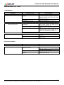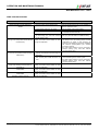
1
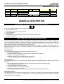
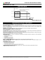
OPERATION AND MAINTENANCE MANUAL
Wall Mounted 0121…0661
OUTDOOR MONOBLOC AIR CONDITIONING
UNIT FOR INSTALLATION ON SHELTERS
AND PRE-FABRICATED BUILDINGS
WMA/WMF
0121- 0181 - 0251 - 0281 - 0331
0551 - 0661
OPERATION AND
MAINTENANCE MANUAL
GB
© UNIFLAIR 2000
Monobloc Wall Mounted Unit - WMA/WMF 0121-0181-0251-0281-0331-0551-0661 - Rev. 2.0. - Date: 18-07-2000 EN
1 (32)
OPERATION AND MAINTENANCE MANUAL
Wall Mounted 0121…0661
Before installing or working on the unit, read this instruction manual
carefully. Follow all instructions and safety procedures contained in
this manual and displayed on the unit
Some characteristics of special versions of these units may differ
from those described in this manual.
UNIFLAIR ITALIA S.r.l.
Via dell’Industria, 10
35020 BRUGINE (Padova) Italy
Tel. +39 (0)49 9713211
Fax. +39 (0)49 5806906
Internet: www.UNIFLAIR.com
E-Mail: [email protected]
Release:
2.0
Date:
18 - 07 - 2000
Checked by:
2 (32)
Monobloc Wall Mounted Unit - WMA/WMF 0121-0181-0251-0281-0331-0551-0661 - Rev. 2.0. - Date: 18-07-2000 EN
OPERATION AND MAINTENANCE MANUAL
Wall Mounted 0121…0661
Contents
Page
GENERAL DESCRIPTION
Documentation enclosed with the unit
Description of the unit and intended use
Function limits
Description of main components
Accessories
Function principles
Free-cooling system
Data plate
4
4
4
5
5
6
7
7
10
START-UP AND TESTING
Start-up procedure
11
11
FUNCTION & REGULATION
Microprocessor control
Management of two units
Measurement and alarm devices
Regulation of condensation pressure
Setting the regulation and safety devices
Setting the airflow sensor
Setting the dirty filter sensor
12
12
13
14
15
16
17
17
TECHNICAL DATA
General characteristics
Electrical characteristics
18
18
20
MAINTENANCE
Regular checks
Cleaning and changing the air filter
Cleaning the external air pre-filter
Cleaning the air-cooled condenser
Damper maintenance – changing the motor
Changing the electrical heating element
Cleaning and changing the condensate drain tube
Adjusting the refrigerant charge
22
22
22
23
23
23
24
24
24
PROBLEM SOLVING
Temperature control
Humidity control
Fans
Refrigerant circuit
Compressors
Electric heaters
Free cooling
26
27
27
28
28
30
30
31
IMPORTANT: the description of the Control System and the operating logic of the unit are given in the
mP20W Control System instruction manual.
Monobloc Wall Mounted Unit - WMA/WMF 0121-0181-0251-0281-0331-0551-0661 - Rev. 2.0. - Date: 18-07-2000 EN
3 (32)
OPERATION AND MAINTENANCE MANUAL
Wall Mounted 0121…0661
Family
W: wall
mounted
W
Unit
type
Function
mode
M: monobloc
M
Model
Number of
Compressors
F: mech.+ free. cooling
A: mech. cooling only
F
Version
C: Basic version
T: With electric re-heat
066
1
T
Control
System
W: mP20W
microprocessor
W
GENERAL DESCRIPTION
DOCUMENTATION ENCLOSED WITH THE UNIT
Every unit is supplied complete with the following documents:
• Unit instruction manual
• Microprocessor control instruction manual
• Electrical diagrams
• Spare parts list
• CE declaration listing the directives and norms to which the unit conforms
• Guarantee certificate
UNIT DESCRIPTION AND INTENDED USE
The WM is an autonomous monobloc direct expansion air conditioning unit with air-cooled condenser, designed for
the air conditioning of telephone exchanges, shelters and technological applications. The unit is pre-charged and
tested in the factory and has its own built-in condenser. Installation consists of simply fixing the unit to the wall,
connecting the air ducting and making the electrical connections.
All essential components can be inspected and removed from the front (with the exception of the damper motor in
WMF units from 0121 to 0331), in multiple installations units can therefore be fitted very close together (see
installation manual).
ACTIVE SAFETY
The control system provides monitoring and prevention functions via:
• Function status indication
• Continuous reading and display of the temperature measured by the sensors
• Indication of fault and alarm situations
• Automatic stopping of unit components in the event of risk
• Compressor management to reduce start-up frequency.
PASSIVE SAFETY
The essential functions of the units are protected against faults and potentially dangerous conditions; WM units are
fitted with:
• High and low-pressure pressostats to protect the refrigerant circuit (HP with manual re-set)
• Low airflow differential pressostat
• Dirty filter differential pressostat (optional)
• Safety thermostat on units with electric heater
• Compressor electric motor protection
• Phase sequence relay on units with 400V/3N/50Hz power supply (models 0331 to 0661).
PERSONAL SAFETY
The design and wiring of Uniflair air conditioning units conform to 73/23/CEE. The electrical panels are equipped
with an auxiliary 24V circuit and include individual short circuit protection using automatic circuit breakers. The axial
fans are protected by metal grilles.
4 (32)
Monobloc Wall Mounted Unit - WMA/WMF 0121-0181-0251-0281-0331-0551-0661 - Rev. 2.0. - Date: 18-07-2000 EN
OPERATION AND MAINTENANCE MANUAL
Wall Mounted 0121…0661
FUNCTION LIMITS
T room air
Only if the condenser is fitted with the
RVC/e speed regulator
T i = 40 °C
T i = 35 °C
T i = 19 °C
T outside air
T e = 18 °C
T e = 45 °C
T e = 47 °C
MODELS WM 0551-0661
DESCRIPTION OF MAIN COMPONENTS
SELF-SUPPORTING FRAME in 1.2 mm galvanised steel
EXTERNAL PANELS in 1.2 mm, galvanised steel with RAL9001 cream-coloured epoxy powder paint and internally
lined in self-extinguishing abrasion-resistant sound and heat insulation material. Units are also available with
aluminium external panels
FILTER in self-extinguishing material with EU2 efficiency (doc. Eurovent 4-5) fitted in rigid metal frame
SINGLE INLET RADIAL FANS in the evaporator section
AIRFLOW SENSOR for activating a low airflow alarm
COOLING COIL: hydrophilic -treated large frontal area manufactured in copper tubing mechanically expanded into
aluminium fins, stainless steel tray with flexible condensate drain tube
ELECTRICAL HEATERS (optional) with finned aluminium elements and safety thermostat for cutting off the power
supply and activating the alarm in the event of overheating
ELECTRICAL PANEL housed in a compartment isolated from the airflow and which conforms to norms 73/23/CEE
- 89/336/CEE with:
• auxiliary 24V transformer
• main switch
• magnetothermal protection
• remote command switches
SCROLL COMPRESSOR with high energy efficiency, low noise levels and built-in thermal.
FREE COOLING (WMF units): managed by the microprocessor which controls a motorised damper for the
introduction of fresh air.
REFRIGERANT CIRCUIT including:
• filter drier and flow sight glass
• thermostatic expansion valve
• high and low-pressure pressostats (HP with manual reset)
mP20W MICROPROCESSOR CONTROL: includes room, outdoor and air delivery temperature sensors
‘TORX’ anti-tamper external screws
Monobloc Wall Mounted Unit - WMA/WMF 0121-0181-0251-0281-0331-0551-0661 - Rev. 2.0. - Date: 18-07-2000 EN
5 (32)
OPERATION AND MAINTENANCE MANUAL
Wall Mounted 0121…0661
ACCESSORIES
The following optional accessories can be added to the basic version of the unit:
RVC/e: condenser fan speed regulation with SPC pressure sensor
USER TERMINAL for the setting and display of unit function parameters; to special order the terminal can be
housed inside the unit’s electrical panel on a hinged plate or a wall fitting kit can be supplied for remote installation
CLOCK CIRCUIT for the management of time and date events
LAN BOARD for the local network connection of two units
LAN & CLOCK BOARD
RS485 SERIAL OUTPUT for data transmission to a centralised supervision system
BLOCKED FILTER ALARM SENSOR consisting of a dirty filter pressostat
EU4 high-efficiency filter (replacing standard EU2 filter)
R407C REFRIGERANT (replacing standard R22)
DOUBLE ELECTRICAL POWER SUPPLY - normal function uses mains power, emergency function uses UPS
230V/1N/50Hz for the fan, microprocessor control and free-cooling damper
DOUBLE ELECTRICAL POWER SUPPLY WITH 48V DC FROM INVERTER: normal function uses mains power,
emergency function uses UPS 48V DC for evaporator fan, microprocessor control and free-cooling damper motor
DC FANS
TEMPERATURE AND HUMIDITY SENSOR (in place of standard temperature-only sensor)
SPRING-RETURN DAMPER to special order on WMF units
6 (32)
Monobloc Wall Mounted Unit - WMA/WMF 0121-0181-0251-0281-0331-0551-0661 - Rev. 2.0. - Date: 18-07-2000 EN
OPERATION AND MAINTENANCE MANUAL
Wall Mounted 0121…0661
FUNCTION PRINCIPLES
(basic version – mechanical cooling)
Air from the room is taken in by the recirculating fan through opening (I),
cooled by the evaporator coil and delivered into the room through opening
(M). In “T” versions, the air may be heated by the electric elements (H) before
being delivered into the room.
H
M
I
Fig. 1
FREE COOLING
(WMF UNITS)
The free cooling cycle consists of the introduction into the room of fresh air when this is sufficiently cold to absorb
the thermal load of the room. The unit is fitted with a butterfly damper and two air intakes:
• recycled air intake (on left hand diagram)
• external air intake (on right hand diagram).
A. NORMAL FUNCTION (figs. 2a and 3a)
During normal function the damper (S) is positioned to take in air only from the room (arrow on the left), closing the
external air intake.
The air is filtered (F), cooled and dehumidified in the cooling coil (E) and returned to the room by the fan (MVE).
Cooling is via the cooling cycle, starting the compressor (CP).
B. FREE COOLING (free cooling) (figs. 2b and 3b)
As soon as the external air is of a low enough temperature to maintain the temperature in the room at the desired
level, the damper (S) changes position, delivering fresh air into the room instead of recycled. During free cooling
function, the compressor is off.
C. MODULATING FUNCTION (fig. 2c and 3c)
When the outside temperature falls further, the control system therefore changes the damper position to mix fresh
and recycled air to maintain room temperature at the required level. In any case, the temperature of the air taken in
is maintained above a pre-set minimum.
Monobloc Wall Mounted Unit - WMA/WMF 0121-0181-0251-0281-0331-0551-0661 - Rev. 2.0. - Date: 18-07-2000 EN
7 (32)
OPERATION AND MAINTENANCE MANUAL
Wall Mounted 0121…0661
MINIMUM QUANTITY OF FRESH AIR
It is possible to pre-set a minimum opening position on the damper to allow the introduction of a proportion of fresh
air in any operating mode.
E
Q.E.
MVE
F
S
CP
MVC
(a)
(b)
(c)
MODELS WMF 0121-0181-0251-0281-0331
Fig. 2
MVE
E
Q.E
F
S
CP
MVC
(a)
(b)
(c)
MODELS WMF 0551-0661
Fig. 3
8 (32)
Monobloc Wall Mounted Unit - WMA/WMF 0121-0181-0251-0281-0331-0551-0661 - Rev. 2.0. - Date: 18-07-2000 EN
OPERATION AND MAINTENANCE MANUAL
Wall Mounted 0121…0661
INTELLIGENT FREE-COOLING
This system gives dynamic control of the free-cooling phase, maximising energy-saving performance at all times.
The result is the ability to provide much greater energy saving (and therefore economy of operation) than the
common fixed-point free-cooling systems.
The microprocessor compares the thermal load present at that moment in the air conditioned environment with the
outside temperature, calculating the optimum temperature at which to start free-cooling. In this way the temperature
at which free-cooling starts is not fixed but changes to adapt to the load conditions present at that moment in the air
conditioned environment
If required, fixed point or fixed differential free-cooling cycles can also be activated; this type of function does not
consider the heat load in the room.
Monobloc Wall Mounted Unit - WMA/WMF 0121-0181-0251-0281-0331-0551-0661 - Rev. 2.0. - Date: 18-07-2000 EN
9 (32)
OPERATION AND MAINTENANCE MANUAL
Wall Mounted 0121…0661
DATA PLATE
The data plate is in the electrical panel housing and shows:
- Unit model and serial number
- Power supply (voltage, number of phases and frequency)
- Power absorption of the unit and of the main components
- Current absorption of the unit and of the main components:
- OA (Operating current)
- FLA (Full load current)
- LRA (Locked rotor current)
- Setting values of the refrigerant circuit pressostats (HP and LP) and of the other regulation and safety devices
- Refrigerant type and refrigerant circuit charge in kg.
MODEL
SERIAL No.
POWER SUPPLY
CURRENT ABSORPTION
OA
FLA
LRA
KW TOTALI
SAFETY DEVICE SETTINGS
REFRIGERANT
Fig. 4
10 (32)
Monobloc Wall Mounted Unit - WMA/WMF 0121-0181-0251-0281-0331-0551-0661 - Rev. 2.0. - Date: 18-07-2000 EN
OPERATION AND MAINTENANCE MANUAL
Wall Mounted 0121…0661
START-UP AND TESTING
START-UP PROCEDURE
Having connected the power supply cables to the IG main switch as described in the Installation Manual, switch on
the power supply to the unit electrical panel.
1. - Arm the IM automatic switch
2. - (in units with double power supply) arm automatic auxiliary switch IM2 (230V/1N/50Hz from UPS)
3. - Move the main switch IG to the on position “I”
4. – Check that the yellow mains LED (on the microprocessor control board) and the user terminal display are both
on (see mP20/W control instruction manual)
5. - (for units with tri-phase power supply) if the RSF phase sequence relay intervenes; disconnect the power
supply, invert two of the phases L1, L2, L3 and continue with the start-up procedure.
WM units can be fitted with two types of RSF phase sequence relay:
a) model:
CDC GZ90F33 (UNIFLAIR code MERE074X1A)
Check that the two orange mains power LEDs and the red RSF LED are on. If the red
RST LED (shown in the diagram) does not come on, disconnect the power supply to
the unit and swap two phases on the power supply cable.
RST
6. – Close the electrical panel cover and tighten the screws;
POWER
CISE 131 - V2R (UNIFLAIR code MERE070X1A)
CISE 131 - V2 (UNIFLAIR code MERE072X1A)
Check that the two orange mains power LEDs and the green Sequence LED on the
RSF relay are on. If the green LED is off, disconnect the power supply to the unit and
swap two phases of the power supply cable
SEQUENZA
b) model:
7. - Start the unit by pressing the
button on the control terminal; after a short delay the fan will start and the
green LED on the control panel will come on. Alternatively the unit can be started by:
- closing the contact between terminals 20 and 50 on the electrical panel if the microprocessor control is
programmed for remote control (see mP20/W instruction manual)
- the supervision system
8. - Check that the protection devices do not intervene
9. - Check that the mP20 control is not displaying an alarm;
An alarm is signalled by:
- the warning buzzer
- activation of the alarm repay and switching on of the red LED on the user terminal
- description of the alarm on the terminal display (see mP20/W instruction manual)
10. – Set the required room parameters (see mP20/W instruction manual) or set the remote control contacts of an
external control system is being used (see attached electrical diagrams); the unit components required to achieve
the set conditions (compressor or free-cooling damper) will be activated.
11. - Check that there are no unusual noises or vibrations
12. - Check that current absorption is within the limits given in the section 'Current Absorption’
13. – Check that the unit has not lost refrigerant charge. If one of the safety devices intervenes check the
evaporation and condensation pressure values with a manometer.
Monobloc Wall Mounted Unit - WMA/WMF 0121-0181-0251-0281-0331-0551-0661 - Rev. 2.0. - Date: 18-07-2000 EN
11 (32)
OPERATION AND MAINTENANCE MANUAL
Wall Mounted 0121…0661
FUNCTION AND REGULATION
MICROPROCESSOR CONTROL
(see mP20 microprocessor control instruction manual)
The control board provides the following functions:
• Control of room temperature
• Display of room relative humidity (with optional temperature and humidity sensor)
• Maximum room humidity setting which, when reached, closes the free-cooling damper and forces compressor
start-up (with optional humidity sensor)
• Management of electrical re-heat (optional)
• Management of alarms
• Management of stand-by if two or more units are connected (with LAN board)
• Alarm system with visual and acoustic signals
• Signal contacts for each type of alarm
• Programmable general alarm signal for the signalling of specific selectable alarms
• Programmable automatic re-start after a power failure
• Programmable re-start delay in multiple installations
• Compressor activation control (limits frequency of start-ups)
• Programmable control (remote control or supervision)
• Control of delivery air minimum temperature limit (WMF)
• Control of free-cooling damper position (special units)
• 2 levels of password programming (setting / hardware & software configuration)
• RS422 or RS485 serial output (optional)
• Clock/calendar circuit (optional)
• Run hour counter for main components
• Service scheduling with clear information on necessary actions
• Memorisation of last 30 alarms (with date and time if optional clock circuit fitted)
• Detailed display of function mode and active components (with optional user terminal)
• Weekly on/off time bands (with optional clock circuit) for weekdays, pre-holidays, holidays
• Set-back function where the unit is in stand-by but maintains room temperature between two pre-set limits and
relative humidity below a pre-set limit (with optional temperature and humidity sensor).
• Distinct setting of heating and cooling set point
• Override function for the manual control of main components without excluding remote control.
• Optimised control algorithm which constantly monitors the temperature of the room, of the air outside and of the
delivery air for optimised management of both the direct expansion and the intelligent free cooling functions.
Free cooling can therefore start earlier and continue for longer and at higher external temperatures since it
takes into account the thermal load in the room at that moment.
• Advanced free-cooling management of two units with stand-by function to maximise energy saving.
12 (32)
Monobloc Wall Mounted Unit - WMA/WMF 0121-0181-0251-0281-0331-0551-0661 - Rev. 2.0. - Date: 18-07-2000 EN
OPERATION AND MAINTENANCE MANUAL
Wall Mounted 0121…0661
MEASUREMENT AND ALARM DEVICES
The safety and regulation functions of the unit are performed by the microprocessor control. The unit is equipped
with the following temperature, humidity and pressure sensors, as shown in the figure below:
RVC/e. Modulates condenser fan speed to control condensation pressure (optional).
TSR. Electric heating element safety thermostat with re-set button under the coil;
SM.
Delivery air temperature sensor;
SE.
External air temperature sensor;
ST-STU. Room temperature (or optional temperature and humidity) sensor. The ST sensor is installed in the unit as
shown in the diagram; the STU sensor is supplied with a 3 metre cable and must be installed in the room.
FS.
Air flow sensor (differential pressostat) to detect low airflow and fan function.
PFS. Dirty filter sensor (differential pressostat).
AP-BP. Fixed setting high / low pressure switches (HP with manual re-set).
SPC. Condensation pressure sensor.
.
STU
TSR
SM
SE
ST
FS
PFS
RVC/e
BP
AP
SPC
BACK OF UNIT
Fig. 5.a.
MODELS WM* 0121-0181-0251-0281-0331
Monobloc Wall Mounted Unit - WMA/WMF 0121-0181-0251-0281-0331-0551-0661 - Rev. 2.0. - Date: 18-07-2000 EN
13 (32)
OPERATION AND MAINTENANCE MANUAL
Wall Mounted 0121…0661
SE
SM
TSR
RVC/e
ST
FS
PFS
AP
SPC
BP
BACK OF UNIT
Fig. 5.b.
MODELS WM* 0551-0661
REGULATION OF CONDENSATION PRESSURE
Standard units are fitted with an On/Off pressostat.
As an alternative, condensation pressure can be
controlled by a TRIAC voltage regulator on the
condenser fan power supply. The regulator is optional
(see Function Limits) and has the code RVC/e; it is
controlled by the microprocessor as a function of the
condensation temperature read by the SPC
condensation pressure sensor.
The setting - done on the user terminal - has the
following standard values:
ON
OFF
DIFFERENTIAL
8 bar
PV
p. COND
CUT-IN (default: 21,5bar)
V
Maximum speed
100%
RVC/e
• minimum speed for 35°C saturated condensation
temperature, corresponding to delivery pressure of
12,7 bar with R22 and 14,5 bar with R407C
• minimum fan power supply voltage (cut-off voltage)
of 15% of mains voltage.
Minimum speed
15%
PROPORTIONAL BAND
T. MIN (default: 35°C)
14 (32)
• maximum speed for 18,5 bar-r condensation
pressure (50°C saturated condensation temperature
with R22 and 47.5°C with R407C)
T. COND
T. MAX (default: 50°C)
Monobloc Wall Mounted Unit - WMA/WMF 0121-0181-0251-0281-0331-0551-0661 - Rev. 2.0. - Date: 18-07-2000 EN
OPERATION AND MAINTENANCE MANUAL
Wall Mounted 0121…0661
Some special units can be fitted with an RVC/p pressostatic speed regulator which is not controlled by the
microprocessor.
Maximum speed:
100%
RVC/p
OFF
PROPORTIONAL BAND
p. MIN (default: 17bar)
p. COND
p. MAX (default: 21bar)
SETTING THE REGULATION AND SAFETY DEVICES
After starting the unit make the following settings:
- Room temperature: see microprocessor control instruction manual
- Room relative humidity: see microprocessor control instruction manual;
- Dirty filter differential pressostat: see section on Setting the Dirty Filter Sensor.
Check that the safety devices are set to the values shown in the table below.
The regulation and safety devices are set in the factory and must not be changed without good reason.
.
AP
BP
TSR
Description
High pressure air delivery pressostat
Low pressure air intake pressostat
Heating element safety thermostat
Intervention
Differential
Re-set
27,5 bar
2,0 bar
320 °C
--1,5 bar
---
manual
3,5 bar
manual
Monobloc Wall Mounted Unit - WMA/WMF 0121-0181-0251-0281-0331-0551-0661 - Rev. 2.0. - Date: 18-07-2000 EN
15 (32)
OPERATION AND MAINTENANCE MANUAL
Wall Mounted 0121…0661
SETTING THE AIRFLOW SENSOR
The FS differential pressostat should intervene if the fan is not working (if the unit has one fan only) or if one of the
fans is not working (in the case of multiple fans).
The setting of the airflow differential pressostat is 1.0 mbar (100 Pa). Since the difference in pressure between the
fan intake and delivery depends on the airflow, it is necessary to set the pressostat after installation, making sure
that the contact closes when the fan is in normal operation. To set the pressostat:
• simulate a fan fault (stop the fan, or one of the fans if multiple); check that the pressostat intervenes
• if the pressostat does not intervene, gradually increase the setting until it does.
The FS differential pressostat can be set on a scale from 0.5 to 5.0 mbar (from 50 to 500 Pa).
SETTING THE OPTIONAL DIRTY FILTER SENSOR
The PFS pressostat must be set as a function of the pressure drop; this depends not only on how dirty the filter is
but also on the airflow and therefore on the setting of the fan speed regulator. The setting must be done when the
filter is clean:
- set the PFS pressostat to 1.5 mbar;
- gradually cover the surface of the air filter and check that the pressostat intervenes when the filter is about 5060% covered
If the pressostat does not intervene, gradually lower its setting; if it cuts in too soon, increase the setting.
16 (32)
Monobloc Wall Mounted Unit - WMA/WMF 0121-0181-0251-0281-0331-0551-0661 - Rev. 2.0. - Date: 18-07-2000 EN
OPERATION AND MAINTENANCE MANUAL
Wall Mounted 0121…0661
TECHNICAL DATA
GENERAL CHARACTERISTICS
This information refers to standard models and may vary for special or modified units.
MODELLO
POTENZA FRIGORIFERA- R22
Raffreddamento Meccanico
Ambiente: 26 °C, 40%UR;Text=35°C
Resa frigorifera totale
Resa frigorifera sensibile
POTENZA FRIGORIFERA
Raffreddamento in free-cooling
Ambiente a 26 °C- Text=14°C
Sensibile
0121
kW
kW
kW
4.1
4.1
5.0
V/ph/Hz
TENSIONE DI ALIMENTAZIONE
COMPRESSORE FRIGORIFERO
Numero / Tipo
1 / ROTARY
Potenza nominale
kW
0.94
(Ambiente a 26°C - Text=35°C)
RISCALDAMENTO ELETTRICO (1)
Numero di stadi
1
Potenza totale
kW
2,6
VENTILATORI sez. RICIRCOLO
Portata d’aria nominale
l/s
(raffreddamento meccanico)
m³/h
Portata d’aria nominale
l/s
(free-cooling)
m³/h
Numero di ventilatori (evaporatore)
VENTILATORI sez. CONDENSANTE
Portata d’aria nominale
l/s
m³/h
Numero di ventilatori / n. di poli
(condensatore)
FILTRO DELL’ARIA
Efficienza - filtro standard
Efficienza - filtro opzionale
Dimensioni
LIVELLO di PRESSIONE SONORA (2)
DIMENSIONI E PESI
Altezza
Larghezza
Profondità
Peso (unità senza imballo)
0181
5.6
5.6
5.8
0251
7.7
7.7
8.5
0281
8.5
8.5
8.5
230/1N/50
0331
MODEL
10.0
10.0
COOLING CAPACITY- R22
Mechanical cooling
Room at 26 °C, 40%RH, Text=35°C
Total cooling capacity
Sensible cooling capacity
9.2
400/3/50
1 / SCROLL
1.53
1.90
2.35
2.86
1
4
1
4
1
4
1
6
344
1240
342
1230
1
406
1460
397
1430
1
622
2240
583
2100
2
622
2240
583
2100
2
742
2670
633
2280
2
794
2860
1/6
794
2860
1/6
800
2890
1/6
800
2890
1/6
825
2970
2/6
570 x 350 x 48
850 x 400 x 48
dB(A)
40.5
44.0
45.5
45.5
49.0
mm
mm
mm
kg
1790
650
400
135
1790
650
400
152
1940
930
450
190
1940
930
450
190
1940
930
450
210
(1) Opzionale
(2) In campo libero, a 5 metri di distanza frontale nelle condizioni
nominali
POWER SUPPLY
COOLING COMPRESSORS
Number of compressors / Type
Nominal power
Room at 26 °C 40%RH, Text=35°C
ELECTRICAL RE-HEAT (1)
Number of stages
Total power
Nominal airflow
(mechanical cooling)
Nominal airflow
(free cooling)
Number of fans (evaporator)
CONDENSER FANS
Nominal air volume
Number of fans (condenser)
AIR FILTER
Efficiency (standard air filter)
Efficiency (optional air filter)
Frontal dimensions
EU2
EU4
mm
COOLING CAPACITY
Free-cooling
Room at 26 °C- Text=14°C
Sensible
SOUND PRESSURE LEVEL (2)
DIMENSIONS AND WEIGHTS
Height
Width
Depth
Weight (unit without packaging)
Optional (1)
Free field at 5 m from front of unit under nominal conditions (2)
MODELLI WM* 0121-0181-0251-0281-0331
Monobloc Wall Mounted Unit - WMA/WMF 0121-0181-0251-0281-0331-0551-0661 - Rev. 2.0. - Date: 18-07-2000 EN
17 (32)
OPERATION AND MAINTENANCE MANUAL
Wall Mounted 0121…0661
MODELLO
POTENZA FRIGORIFERA – R22
Raffreddamento Meccanico
Ambiente a 26 °C- 40%URText=35°C
Resa frigorifera totale
Resa frigorifera sensibile
WMF0551
MODEL
WMF0661
COOLING CAPACITY – R22
Mechanical cooling
Room at 26 °C- 40%RH- Text=35°C
kW
kW
15.8
15.8
17.5
17.5
kW
kW
POTENZA FRIGORIFERA
Raffreddamento in free-cooling
Ambiente a 26 °C- Text=14°C
Sensibile
kW
17.4
17.4
kW
TENSIONE DI ALIMENTAZIONE
V/ph/Hz
400/3+N/50 (*)
400/3+N/50 (*)
V/ph/Hz
1 / SCROLL
1 / SCROLL
kW
4.01
4.88
kW
1
6
1
6
l/s
m³/h
l/s
m³/h
1270
4580
1200
4310
1
1270
4580
1200
4310
1
l/s
m³/h
l/s
m³/h
l/s
m³/h
1650
5940
1
1650
5940
1
l/s
m³/h
COMPRESSORE FRIGORIFERO
Numero / Tipo
Potenza nominale
(Ambiente a 26°C - Text=35°C)
RISCALDAMENTO ELETTRICO (1)
Numero di stadi
Potenza totale
VENTILATORI sez. RICIRCOLO
Portata d’aria nominale
(raffreddamento meccanico)
Portata d'aria nominale
(free cooling)
Numero di ventilatori
VENTILATORI sez. CONDENSANTE
Portata d’aria nominale
Numero di ventilatori
Total cooling capacity
Sensible cooling capacity
COOLING CAPACITY
Free-cooling
Room at 26 °C- Text=14°C
Sensible
POWER SUPPLY
kW
COOLING COMPRESSORS
Number / Type
Nominal power
Room at 26 °C 40%RH, Text=35°C
kW
ELECTRICAL RE-HEAT (1)
Number of stages
Total power
Nominal airflow
(mechanical cooling)
Nominal airflow
(free cooling)
Number of fans
CONDENSER FANS
Nominal air volume
Number of fans
AIR FILTER
Efficiency (standard air filter)
Efficiency (optional air filter)
Dimensions
FILTRO DELL’ARIA
Efficienza - filtro standard
Efficienza - filtro opzionale
Dimensioni
mm
965 x 590 x 48
965 x 590 x 48
mm
LIVELLO DI PRESSIONE SONORA (2)
dB(A)
51.0
51.0
dB(A)
SOUND PRESSURE LEVEL(2)
DIMENSIONI E PESI
Altezza
Larghezza
Profondità
Peso (unità senza imballo)
mm
mm
mm
kg
2250
1050
625
300
2250
1050
625
320
mm
mm
mm
kg
DIMENSIONS AND WEIGHTS
Height
Width
Depth
Weight (unit without packaging)
EU2
EU4
(1) Opzionale
(2) In campo libero, a 5 m di distanza frontale nelle condizioni
nominali
(*) in alcune versioni, oltre all'alimentazione principale
400V/3ph+N/50Hz, può essere prevista l'alimentazione secondaria
230V/1N/50Hz (UPS).
18 (32)
mm
Optional (1)
Free field at 5 m from front of unit under nominal conditions (2)
Monobloc Wall Mounted Unit - WMA/WMF 0121-0181-0251-0281-0331-0551-0661 - Rev. 2.0. - Date: 18-07-2000 EN
OPERATION AND MAINTENANCE MANUAL
Wall Mounted 0121…0661
AIR FLOW
RECIRCULATION (1)
MODEL
Nominal air flow @ 0 Pa
Air flow @ 50 Pa
Air flow @ 100 Pa
Air flow @ 150 Pa
l/s
m³/h
l/s
m³/h
l/s
m³/h
l/s
m³/h
MODEL
Nominal air flow @ 0 Pa
Air flow @ 50 Pa
Air flow @ 100 Pa
Air flow @ 150 Pa
l/s
m³/h
l/s
m³/h
l/s
m³/h
l/s
m³/h
WM∗
∗0121
WM∗
∗0181
WM∗
∗0251
WM∗
∗0281
WM∗
∗0331
344
1240
308
1110
267
960
214
770
406
1460
372
1340
333
1200
286
1030
622
2240
556
2000
478
1720
381
1370
622
2240
556
2000
478
1720
381
1370
742
2670
675
2430
603
2170
519
1870
WM∗
∗0551
WM∗
∗0661
1270
4580
1208
4350
1139
4100
1067
3840
1270
4580
1208
4350
1139
4100
1067
3840
(1) Without delivery and intake grilles, clean filters, no electric heater or re-heat
FREE-COOLING (1)
MODEL
Nominal air flow @ 0 Pa
Air flow @ 50 Pa
Air flow @ 100 Pa
Air flow @ 150 Pa
l/s
m³/h
l/s
m³/h
l/s
m³/h
l/s
m³/h
MODEL
Nominal air flow @ 0 Pa
Air flow @ 50 Pa
Air flow @ 100 Pa
Air flow @ 150 Pa
l/s
m³/h
l/s
m³/h
l/s
m³/h
l/s
m³/h
WMF0121
WMF0181
WMF0251
WMF0281
WMF0331
342
1230
308
1110
258
930
208
750
397
1430
372
1340
325
1170
278
1000
583
2100
508
1830
422
1520
333
1200
583
2100
508
1830
422
1520
333
1200
633
2280
575
2070
506
1820
439
1580
WMF0551
WMF0661
1200
4310
1137
4092
1071
3857
1003
3612
1200
4310
1137
4092
1071
3857
1003
3612
(1) Without delivery and intake grilles, clean filters, no electric heater or re-heat
Monobloc Wall Mounted Unit - WMA/WMF 0121-0181-0251-0281-0331-0551-0661 - Rev. 2.0. - Date: 18-07-2000 EN
19 (32)
OPERATION AND MAINTENANCE MANUAL
Wall Mounted 0121…0661
ELECTRICAL CHARACTERISTICS
UNIT COMPONENTS
COMPONENTI DELL’UNITÁ
COMPRESSORE
COMPRESSOR
C
50 Hz
VENTILATORI sez. RICIRCOLO
RADIAL FANS
MVE
VOLT
No.
LRA
VOLT
No.
kW
OA
FLA
LRA
WM∗
∗ 0121
WM∗
∗ 0181
WM∗
∗ 0251
WM∗
∗ 0281
230/1ph/50
230/1ph/50
230/1ph/50
230/1ph/50
1
1
1
1
0.94
1.53
1.90
2.35
4,4
7,1
9,0
11,2
8,5
11,4
13,6
15,3
32
47
61
76
230/1ph/50
230/1ph/50
230/1ph/50
230/1ph/50
1
1
2
2
0,13
0,23
0,13
0,13
0,6
1,0
0,6
0,6
0,67
1,11
0,67
0,67
1,45
2,22
1,45
1,45
WM∗
∗ 0331
WM∗
∗ 0551
WM∗
∗ 0661
400/3ph/50
400/3ph/50
400/3ph/50
1
1
1
2.86
4.01
4.88
5,1
7.8
8.6
6,6
10.0
11.4
46
66
74
230/1ph/50
230/1ph/50
230/1ph/50
2
1
1
0,23
0.70
0.70
1,0
3.2
3.2
1,11
3.56
3.56
2,22
7
7
MVC
kW (2) OA (2) FLA
VENTILATORI sez. CONDENSANTE
CONDENSER FANS
kW (2) OA (2) FLA
RESISTENZE ELETTRICHE (opzionali)
ELECTRICAL HEATERS (optional)
RR
VOLT
No.
LRA
VOLT
No.
kW
OA
WM∗
∗ 0121
WM∗
∗ 0181
WM∗
∗ 0251
WM∗
∗ 0281
230/1ph/50
230/1ph/50
230/1ph/50
230/1ph/50
1
1
1
1
0,14
0,14
0,14
0,14
0,5
0,5
0,5
0,5
0
0
0
0
0
0
0
0
230/1ph/50
230/1ph/50
230/1ph/50
230/1ph/50
2
2
2
2
1,3
2.0
2.0
2.0
5,6
8,7
8,7
8,7
WM∗
∗ 0331
WM∗
∗ 0551
WM∗
∗ 0661
230/1ph/50
230/1ph/50
230/1ph/50
2
1
1
0,09
0.34
0.34
0,4
1.5
1.5
0
2,56
2,56
0
7
7
230/1ph/50
400/3ph/50
400/3ph/50
2
1
1
3.0
6.0
6.0
8.7
8.7
8.7
COMPLETE UNITS
UNITÁ COMPLETE
SENZA RESISTENZE
WITHOUT EL. HEATERS
RAFFREDDAMENTO MECCANICO
MECHANICAL COOLING
CICLO DI FREE-COOLING
FREE-COOLING CYCLE
mm²
FUS
VOLT
kW
L1
L2
L3
VOLT
kW
L1
L2
L3
WM∗
∗ 0121 C
WM∗
∗ 0221 C
WM∗
∗ 0251 C
WM∗
∗ 0281 C
1,5
1,5
2,5
2,5
30A
30A
40A
40A
230/1ph/50
230/1ph/50
230/1ph/50
230/1ph/50
1.21
1.9
2.30
2.75
5.5
8.6
10.7
12.9
0
0
0
0
0
0
0
0
230/1ph/50
230/1ph/50
230/1ph/50
230/1ph/50
0.13
0.23
0.26
0.26
0.6
1.0
1.2
1.2
0
0
0
0
0
0
0
0
WM∗
∗ 0331 C
WM∗
∗ 0551 C
WM∗
∗ 0661 C
1,5
4
4
30A
40A
40A
400/3ph/50+N
400/3ph/50+N
400/3ph/50+N
3.49
5.05
5.92
7.9
12.5
13.3
5,1
7.8
8.6
5,1
7.8
8.6
400/3ph/50+N
400/3ph/50+N
400/3ph/50+N
0.46
0.70
0.70
2.0
3.2
3.2
0
0
0
0
0
0
CON RESISTENZE
WITH EL. HEATERS
RISCALDAMENTO ELETTRICO
ELECTRICAL HEATING
DEUMIDIFIC. & POSTRISC. ELETTRICO
DEHUMIDIFICATION & ELECTRIC REHEAT
mm²
FUS
VOLT
kW
L1
L2
L3
VOLT
kW
L1
L2
L3
WM∗
∗ 0121 T
WM∗
∗ 0221 T
WM∗
∗ 0251 T
WM∗
∗ 0281 T
4
4
6
6
40A
40A
50A
50A
230/1ph/50
230/1ph/50
230/1ph/50
230/1ph/50
2.73
4.23
4.26
4.26
11.8
18.4
18.6
18.6
0
0
0
0
0
0
0
0
230/1ph/50
230/1ph/50
230/1ph/50
230/1ph/50
3.81
5.90
6.3
6.75
16.7
26.0
28.1
30.3
0
0
0
0
0
0
0
0
WM∗
∗ 0331 T
WM∗
∗ 0551 T
WM∗
∗ 0661 T
2,5
4
4
40A
40A
40A
400/3ph/50+N
400/3ph/50+N
400/3ph/50+N
6.46
6.70
6.70
10.7
11.9
11.9
8.7
8.7
8.7
8.7
8.7
8.7
400/3ph/50+N 9.49
400/3ph/50+N 11.05
400/3ph/50+N 11.92
16.6
21.2
22.0
13.8
16.5
17.3
13.8
16.5
17.3
20 (32)
kW
OA
FLA
LRA
kW
A
A
A
L1-L2-L3
mm²
FUS
A
mm²
A
Potenza Nominale (1)
Assorbimento nominale (1)
Assorbimento massimo (1)
Corrente di spunto (1)
(1) per elemento
(2) Ambiente: 26°C/40%UR - Test.: 35°C
Assorbimento nominale per fase
Sez. cavo di alimentazione consigliata
Fusibile di linea consigliato
Nom. Absorbed Power (1)
Operating Current (1)
Full Load Current (1)
Locked Rotor Current (1)
(1) each Element
(2) Room at: 26°C / 40% - Text.: 35°C
Operating Current per phase
Supply Wiring Section suggested
Line Back-up Fuses suggested
Monobloc Wall Mounted Unit - WMA/WMF 0121-0181-0251-0281-0331-0551-0661 - Rev. 2.0. - Date: 18-07-2000 EN
OPERATION AND MAINTENANCE MANUAL
Wall Mounted 0121…0661
MAINTENANCE
REGULAR CHECKS
The following maintenance operations should be done regularly:
•
•
•
•
•
•
•
•
•
•
•
check the set values of the control and regulation devices
check that room conditions on the mP20/W terminal display are normal
check normal condensation and evaporation pressures or saturated temperatures
check the refrigerant charge; the sight glass should be clear (however the presence of a few bubbles is normal
check the correct function of the external air damper
check normal temperature and noise levels of compressor and fans
check the air filters; clean or change the filters when the dirty filter alarm comes on
check the flow of condensate to the drain
check whether the condenser is dirty, removing any obstructing material with a jet of compressed air or water
check that all electric terminal connections are tight
check that power supply voltage is within design limits.
CLEANING AND CHANGING THE AIR FILTER
Inspect the filter cartridge at least once a
month and whenever there is a blocked filter
alarm: Clean or chage the filter as necessary.
WM 0121…0331
WM 0551-0661
models 0121-0331 open the central front panel
models 0551…0661 open the top front panel
F
F
- remove the filter cartridge (F), shake it to
remove large particles then clean with a
vacuum cleaner. Change the filter if it is
blocked.
Fig. 6.
Monobloc Wall Mounted Unit - WMA/WMF 0121-0181-0251-0281-0331-0551-0661 - Rev. 2.0. - Date: 18-07-2000 EN
21 (32)
OPERATION AND MAINTENANCE MANUAL
Wall Mounted 0121…0661
CLEANING THE FRESH AIR PRE-FILTRER
(only in units with free-cooling option)
To ensure sufficient flow of fresh air the metal pre-filter on the front air
intake must be cleaned regularly, especially during the cooler seasons
when free-cooling is used more often.
Free the pre-filter (F) from the air intake (N) and clean it using
compressed air or water and detergent.
The free-cooling function should not be used without the pre-filter
installed.
N
Fig. 7.
F
CLEANING THE CONDENSER
If the fins of the condenser coil are obstructed, remove all foreign bodies (leaves, seeds, dead animals, etc.) with
compressed air.
CHANGING THE DAMPER MOTOR
Check the free flow of air through the damper and the condition of the neoprene rubber, making sure that the edges
form a tight seal.
In an emergency (for example if the motor breaks) or for maintenance, press the motor release catch (fig.8 A) to
move the damper manually). The damper motor can be accessed after removing the side panel in models
WM*0121 - 0331 or the top front panel in models WM*0551 - 0661. To take out the motor, undo fixing screws B
completely and remove the motor from the damper shaft.
WM 0121…0331
WM 0551-0661
A
B
Fig. 8.
22 (32)
Monobloc Wall Mounted Unit - WMA/WMF 0121-0181-0251-0281-0331-0551-0661 - Rev. 2.0. - Date: 18-07-2000 EN
OPERATION AND MAINTENANCE MANUAL
Wall Mounted 0121…0661
CHANGING THE ELECTRIC HEATING ELEMENTS
(models WM* 0551-0661)
The heater elements are in front of the MVE radial fan: for access,
remove the top front panel of the unit and the safety cover.
IMPORTANT: before working on the electric heating element, switch
off the power supply by moving the main switch to the OFF position
(O) and wait for the element to cool.
CLEANING AND CHANGING THE CONDENSATE DRAIN TUBE
If necessary, change the condensate drain tube starting from the drain tray under the evaporator coil. To clean the
tube, disconnect it from the tray and use a use a jet of water.
ADJUSTING THE REFRIGERANT CHARGE
The unit’s refrigerant circuit is supplied already charged with R22 or R407C.
Check the type of refrigerant to use on the data plate of the unit and of the compressor.
If necessary, top up the charge using only the refrigerant and oil specified in the unit manual. Drain the refrigerant
circuit completely, making sure that no refrigerant gas leaks into the environment, then create a vacuum in the
circuit. A pressure of less than 100 Pa absolute (0,7 mm Hg) must be maintained in order to evacuate all air and
moisture traces.
Start the compressor and slowly charge the refrigerant circuit via the special valve until the pressure in the line
stabilises and the bubbles in the sight glass disappear. This valve is on the vertical section of piping immediately
downstream of the thermostatic valve
Thermostatic valve
Sight
glass
Filter Drier
Monobloc Wall Mounted Unit - WMA/WMF 0121-0181-0251-0281-0331-0551-0661 - Rev. 2.0. - Date: 18-07-2000 EN
23 (32)
OPERATION AND MAINTENANCE MANUAL
Wall Mounted 0121…0661
The charge must be done under room conditions and with a discharge pressure of around 18 bar (equivalent to a
saturation temperature of 48°C for R22).
Check that the super-cooling of the liquid at the intake of the thermostatic valve is between 3 and 5°C less than the
condensation temperature reading on the manometer scale and that the superheating of the vapour at the
evaporator output is around 5-8°C.
Oil: the average dilution is around 5% by weight of the refrigerant charge. If it is necessary to add oil, use only the
recommended type below:
Refrigerant
Recommended oil
R22 (Mineral oil) Suniso 3 GS
Mobil EAL Arctic 22 CC
R407C (POE)
24 (32)
Texaco WF 32
ICI EMKARATE RL 32S
Fuchs KM
Monobloc Wall Mounted Unit - WMA/WMF 0121-0181-0251-0281-0331-0551-0661 - Rev. 2.0. - Date: 18-07-2000 EN
OPERATION AND MAINTENANCE MANUAL
Wall Mounted 0121…0661
PROBLEM SOLVING
Identifying and solving problems is made easier by the microprocessor control which, in the event of an alarm:
• activates the alarm relay as well as the red LED and buzzer on the user terminal
• displays an alarm condition on the user terminal
• describes, via the appropriate routine, the nature of the alarm and the possible solution.
If the HP pressostat or electric heater safety thermostat intervene they must be re-set manually using the button on
the device.
Many problems can be caused by loose terminal connections. In the event of an alarm,
check that all wires are securely fixed in the terminals.
If there is a fault, contact the nearest authorised Service Centre, giving the nature of the fault and any probable
causes. Always consult the Microprocessor Control Manual included with the unit - many problems which seem to
be faults are simply a question of incorrect or incomplete programming of the control.
PROBLEM
POSSIBLE CAUSE
CHECK / REMEDY
NO POWER
A) No power to the unit electrical panel 1) Check that power is on and the unit main switch
and/or no power to the auxiliary circuit.
on the electrical panel is closed; check that the IM
automatic circuit breaker is set..
2) Check the auxiliary circuit 24V fuse and the
(The yellow LED on the mP20 board is
fuse on the mP20 board
off).
The message appears:
WARNING! PHASE SEQUENCE ERROR
The phase sequence is inverted (models Check that both LEDs on the RSF phase
with 400V/3N/50Hz power supply).
sequence relay are on. If not, disconnect the
power supply then swap two of the power supply
phases.
If the alarm comes when the unit is operating the
LP pressostat may have tripped: Check the
pressure in the refrigerant circuit in the sec tion
subject to evaporation pressure.
THE UNIT DOES NOT WORK
The control panel does not start the Check that the control panel connectors are
unit.
correctly located in their sockets; see
mP20/W control panel instruction manual..
Check the control panel for alarms
See mP20/W control panel instruction manual
The circuit does not receive the With a remote control system, check that the
function command in remote control contact between terminals 20 and 50 is
closed
mode
Monobloc Wall Mounted Unit - WMA/WMF 0121-0181-0251-0281-0331-0551-0661 - Rev. 2.0. - Date: 18-07-2000 EN
25 (32)
OPERATION AND MAINTENANCE MANUAL
Wall Mounted 0121…0661
TEMPERATURE CONTROL
PROBLEM
POSSIBLE CAUSE
CHECK / REMEDY
ROOM TEMPERATURE TOO HIGH
The parameter settings on the control
panel are not correct
Lack of air flow.
The compressor does not work when
called by the control panel.
Insufficient compressor output
Check the room temperature setting; see
control panel instruction manual.
See ”Lack Of Air Flow”.
See ”The Compressor Does Not Work”.
(high room temperature alarm)
The control system does not work
properly
Heat load higher than expected.
ROOM TEMPERATURE TOO LOW
(Low room temperature alarm)
See ”Compressor High Output Pressure”,
”Compressor Low Intake Pressure”.
See the control panel instruction manual;
check that the control panel and sensors
work properly.
Check: fresh air conditions and volume,
external air infiltration and latent load,
particularly with dehumidification.
The parameter settings on the control Check the room temperature setting; see the
panel are not correct.
control panel instruction manual
Electric heater does not work.
1) Check electric heater operation
2) Check electric heater power supply
3) If there is a heater alarm, remove the
cause and re-set the safety thermostat
The control system is not working.
See control panel instruction manual; check
that control panel and/or sensors work
properly.
Thermal leakage higher than expected Check thermal leakage and entry of external
air.
HUMIDITY CONTROL
PROBLEM
ROOM HUMIDITY TOO HIGH
(High room humidity alarm)
POSSIBLE CAUSE
A) The parameter settings on the
control panel are not correct.
B) Latent load higher than expected
C) The compressor does not function
during dehumidification.
D) The control system is not working.
ROOM HUMIDITY TOO LOW
(Low room humidity alarm)
26 (32)
CHECK / REMEDY
Check room humidity settings; see the
control panel instruction manual.
Check: latent load, fresh air conditions and
volume, external air infiltration
See “The Compressor Doesn’t Work”
See control panel instruction manual; check
that control panel and sensors work properly.
A) The parameter settings on the Check the room temperature setting; see
control panel are not correct.
also the control panel instruction manual.
B) Latent load lower than expected.
Check: quantity of the latent load, fresh air
conditions and volume, external air
infiltration
Monobloc Wall Mounted Unit - WMA/WMF 0121-0181-0251-0281-0331-0551-0661 - Rev. 2.0. - Date: 18-07-2000 EN
OPERATION AND MAINTENANCE MANUAL
Wall Mounted 0121…0661
FANS
PROBLEM
LACK OF AIRFLOW
POSSIBLE CAUSE
A) No power to the fans
B) The filters are dirty
C) The airflow is obstructed
D) Intervention of fan
protection.
CHECK / REMEDY
Check power supply to the fan motors
Shake dust out of the cartridge and clean
with a vacuum cleaner. Change filter if
blocked. Check correct setting of the dirty
filter pressostat.
Read the section on Air Distribution
thermal Check the resistance of the fan windings.
Re-set then measure voltage and current.
E) The pressure drop in the air distribution 1) Check the air distribution system
system (grilles, ducts, etc.) is too high.
2) Increase fan speed (see Fan Speed Regulation)
REFRIGERANT CIRCUIT
PROBLEM
POSSIBLE CAUSE
CHECK / REMEDY
HIGH COMPRESSOR OUTPUT
PRESSURE
A) Non-condensable air or gas in the
circuit, with bubbles in the flow sight
glass; supercooling of the liquid is
high.
B) Airflow is insufficient or air in the
remote condenser is too warm.
Evacuate the refrigerant circuit and recharge
1) Check fan operation and rotation direction
in the remote heat exchanger. (See
condenser/radiator instruction manual).
2) Remove any obstructions from the remote
condenser with compressed air or water.
C) Too much refrigerant in the circuit; Remove some refrigerant from the circuit.
condenser
partially
flooded.
Refrigerant supercooling too high at
condenser output
HIGH PRESSURE PRESSOSTAT
INTERVENES
LOW COMPRESSOR OUTPUT
PRESSURE
A) The condensation pressure control 1) Check condenser fan; re-set or replace
system is not functioning efficiently
the faulty fans;
2) Check setting and function of the RVC/e.
speed regulator (see Regulation of
condensation pressure)
B) High system output pressure
See High compressor output pressure
A) The condensation pressure control
system
is
not
working
(see
microprocessor control instruction
manual).
B) Intake pressure too low
1) Check the function and setting of the
condenser fan pressostat and speed
regulator
See Low Compressor Intake Pressure.
Monobloc Wall Mounted Unit - WMA/WMF 0121-0181-0251-0281-0331-0551-0661 - Rev. 2.0. - Date: 18-07-2000 EN
27 (32)
OPERATION AND MAINTENANCE MANUAL
Wall Mounted 0121…0661
REFRIGERANT CIRCUIT
PROBLEM
HIGH COMPRESSOR INTAKE
PRESSURE
POSSIBLE CAUSE
CHECK/REMEDY
A) Heat Load greater than expected.
B) Airflow pressure too high.
C) Circuit refrigerant overload
D)Return of liquid refrigerant
compressor intake.
LOW COMPRESSOR INTAKE
PRESSURE
(and formation of frost in the coil)
to
A) Room temperature is too low.
See “ROOM TEMPERATURE IS TOO LOW”.
B) Air flow is too low or absent.
C) Refrigerant filter is blocked.
D) Thermostat Valve is un-set or faulty.
SEE “LOW AIR FLOW”.
Check the refrigerant filter.
Check that the overheating of the thermostat valve
is correct (approx 5-8°C); check that the valve
sensor bulb has not lost its refrigerant charge and
that it is correctly positioned, fixed and isolated.
Check for any leakage and restore the load to
measure a sub-cooling of the condensor liquid
outlet of 3-5°C.
E) Insufficient refrigerant load.
INTERVENTION OF THE
PRESSOSTAT BP
(low compressor intake pressure)
A) Thermostat valve is un-set or faulty.
Check that the overheating of the thermostat valve
is correct (approx 5-8°C).
B) filter cartridge is dirty. deidratore
Check that the cartridge dehydrator filter doesn’t
need to be replaced; the difference between the
air temperature measured before and after the
filter must be less than 2°C.
see
“LOW
COMPRESSOR
OUTPUT
PRESSURE” .
C)Output pressure is too low.
28 (32)
Check the consistency of the room thermal load;
check, in the presence of strong dehumidification,
the airflow and the external conditions; check the
amount of outside air draw.
See
“HIGH
COMPRESSOR
OUTPUT
PRESSURE”.
Remove the refrigerant from the circuit.
the Check that the overheating of the thermostat valve
is correct (approx 5-8°C); check that the valve
sensor bulb has not lost its refrigerant charge and
is well positioned, fixed and isolated.
Monobloc Wall Mounted Unit - WMA/WMF 0121-0181-0251-0281-0331-0551-0661 - Rev. 2.0. - Date: 18-07-2000 EN
OPERATION AND MAINTENANCE MANUAL
Wall Mounted 0121…0661
COMPRESSOR
PROBLEM
THE COMPRESSOR DOES NOT WORK
POSSIBLE CAUSE
CHECK/REMEDY
A) Protection device against short circuit is Restore the magnetic switch lever; check cause of
switched on.
the short circuit. Before restarting the compressor
check the. heating element and the winding
continuity of the motor.
B)The internal protection of the compressor see ‘COMPRESSOR INTERNAL PROTECTION
is switched on.
DEVICE SWITCHES ON’
C) The contactor doesn’t work.
Check the contacts and the main switch coil.
COMPRESSOR INTERNAL PROTECTION A) Lack of phase (unit power supply Check the compressor winding heating elements,
DEVICE SWITCHES ON
400V/3N/50Hz)
after re-setting, measure the voltage and the
absorption of the three phases.
B) Motor overload.
Check that the unit is functioning within the pre-set
limits.
C) Power supply voltage is too high or too Check the unbalance between the phases of the
low.
three phase power supply are within 2%.. For
monophase components the voltage must be
between -10% and +6% the nominal value.
D)Blocked rotor.
Replace the compressor.
THE COMPRESSOR IS NOISY
A) The compressor is damaged.
B) Liquid return to the compressor.
Call the nearest Help Center to replace the
compressor.
Check the functioning and overheating of the
expansion valve.
ELECTRIC HEATERS
PROBLEM
ELECTRIC HEATERS DO NOT
POSSIBLE CAUSE
CHECK/REMEDY
The safety thermostat of the heating Airflow is insufficient see “LOW AIRFLOW”.
elements is switched on.
Check the continuity of the safety thermostat
connection to the control system.
The contactor doesn’t work.
Check the contactor contacts and the electric coil.
Protection device against short circuit is Check the cause of the short circuit and re-set the
switched on.
automatic switch lever IM.
Monobloc Wall Mounted Unit - WMA/WMF 0121-0181-0251-0281-0331-0551-0661 - Rev. 2.0. - Date: 18-07-2000 EN
29 (32)
OPERATION AND MAINTENANCE MANUAL
Wall Mounted 0121…0661
FREE COOLING SYSTEM
PROBLEM
FREE-COOLING CYCLE DOES NOT
START
POSSIBLE CAUSE
CHECK/REMEDY
A) The servomotor damper doesn’t work.
Check the electrical of the and if it is necessary to
replace or repare the motor.
B) Control system setting is not correct.
C) The control system doesn’t work.
Check the setting of the control system.
Check the functioning of the sensors.
Cfr. mP20/W instruction manual.
D) the main board does not receive consent Check that the connection of external consent is
of free-cooling (only units with external correct (cfr. par.ELECTRICAL CONNECTIONS)
control system CDC).
ROOM TEMPERATURE IS TOO HIGH
The free-cooling damper is open on the 1) The damper motor doesn’t work; manually set
(the high room temperature threshold alarm outside; hot and/or humid outside air flows
the damper in the recirculating position to await
is switched on)
through the evaporator.
replacement or repair. 2) the minimum set
opening of the damper is excessive; recalibrate
the minimum openingritarare (Cfr. mP20/W
instruction manual);
3) the main board receives a wrong command of
damper opening (only units with external
control systems CDC).
ROOM TEMPERATURE IS TOO LOW
A) The free-cooling damper is open on the see ROOM TEMPERATURE IS TOO HIGH
(the low room temperature threshold alarm is
outside; cold outside air flows through the
evaporator.
switched on.)
B) The modulation of the damper does not 1) The setting of the control system is not correct:
work correctly with outside air that is too
check the setting of the control system.
cold.
2) the base board receives a wrong command of
damper opening (only units with external
control systems CDC).
ROOM HUMIDITY IS TOO HIGH
The free-cooling damper is open on the See “ROOM TEMPERATURE IS TOO HIGH”
(high room humidity threshold alarm is
outside; hot and/or humid outside air flows
through the evaporator.
switched on)
HIGH COMPRESSOR CHARGE
The free-cooling damper is open on the See "ROOM TEMPERATURE IS TOO HIGH"
PRESSURE
outside; hot and/or humid outside air flows
through the evaporator.
LOW COMPRESSOR CHARGE
The free-cooling damper is open on the see "ROOM TEMPERATURE IS TOO HIGH"
PRESSURE
outside; hot and/or humid outside air flows
(formation of frost in the coil)
through the evaporator.
30 (32)
Monobloc Wall Mounted Unit - WMA/WMF 0121-0181-0251-0281-0331-0551-0661 - Rev. 2.0. - Date: 18-07-2000 EN