1
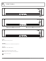
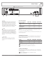
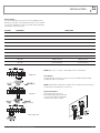
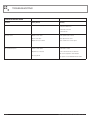
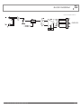
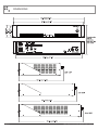
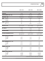
INSTALLATION AND OPERATION MANUAL
AMC+ SERIES
POWER AMPLIFIERS
AMC+120P
AMC+250P
AMC+1202P
IMPORTANT SAFETY INFORMATION
PRÉCAUTIONS DURANT UTILISATION
1.
Read these instructions.
1.
LISEZ ces instructions.
2.
Keep these instructions.
2.
Tenez ces instructions.
3.
Heed all warnings.
3.
Notez tous les avertissements.
4.
Follow all instructions.
4.
Suivez toutes les avertissements.
5.
Do not use this apparatus near water.
5.
N’utilisez pas ce produit près de l’eau (la piscine, la plage, le lac, etc.).
6.
Clean only with dry cloth.
6.
Nettoyez seulement avec une étoffe sèche.
7.
Do not block any ventilation openings. Install in accordance with the
manufacturer’s instructions.
7.
Ne bloquez aucuns troux de ventilation. Installez en accord avec
les instructions du manufacturier.
8.
Do not install near any heat sources such as radiators, heat registers,
stoves, or other apparatus (including amplifiers) that produce heat.
8.
9.
Do not defeat the safety purpose of the polarized or grounding-type plug.
A polarized plug has two blades with one wider than the other.
A grounding type plug has two blades and a third grounding prong.
The wide blade or the third prong are provided for your safety. If the
provided plug does not fit into your outlet, consult an electrician for
replacement of the obsolete outlet.
N’installez près aucunes sources de chaleur comme radiateurs, registres
de chaleur, fours ou les autres équipements (y compris amplificateurs)
qui produisent la chaleur.
9.
Ne défaites pas le but de sécurité de la fiche polarisée ou base-type.
Une fiche polarisée a deux tranchants avec un plus large que l’autre.
Une fiche de base type a deux a deux tranchants et une troisième
pointe de base, le tranchant large ou la troisième pointe est fourni
pour votre sécurité. Si la fiche donnée ne conforme pas votre prise
de contact, consultez un électricien pour remplacement de la prise
de contact obsolète.
10. Protect the power cord from being walked on or pinched particularly
at plugs, convenience receptacles, and the point where they exit from
the apparatus.
11. Only use attachments/accessories specified by the manufacturer.
12. Use only with the cart, stand, tripod, bracket, or table specified by the
manufacturer, or sold with the apparatus. When a cart is used, use caution
when moving the cart/apparatus combination to avoid injury from tip-over.
13. Unplug this apparatus during lightning storms or when
unused for long periods of time.
14. Refer all servicing to qualified service personnel.
Servicing is required when the apparatus has been
damaged in any way, such as power-supply cord or plug
is damaged, liquid has been spilled or objects have fallen into the
apparatus, the apparatus has been exposed to rain or moisture, does
not operate normally, or has been dropped.
15. This appliance shall not be exposed to dripping or splashing water and
that no object filled with liquid such as vases shall be placed on the
apparatus.
16. Plug this apparatus to the proper wall outlet and make the plug to be
disconnected readily operable.
17. Mains plug is used as disconnected device and it should remain readily
operable during intended use. In order to disconnect the apparatus from
the mains completely, the mains plug should be disconnected from the
mains socket outlet completely.
18. WARNING: To reduce the risk of fire or electric shock, do not expose this
apparatus to rain or moisture.
19. An appliance with a protective earth terminal should be connected to a
mains outlet with a protective earth connection.
20. AMC+120P, AMC+250P, AMC+1202P - Risk of hazardous voltage.
Class 3 wiring should be used.
21. The apparatus should be disconnected from the mains completely before
speaker wiring. The speaker output should be proper protected from
direct contact and pay attention to speaker connections, terminals and
speaker wiring during normal operation.
10. Protegez le cordon de secteur contre être marchée dessus ou pincez
en particulier aux fiches, aux douilles de convenance, et au point où ils
sortent de l’appareil.
11. Seulement utilisez attachements/accessoires spécifiés par le
manufacturier.
12. Utilisez seulement avec un chariot, un stand, un trépied, un support
ou une table indiquée par le manufacturier, ou vendue avec l’appareil.
Quand un chariot est utilisé, faites attention en déplaçant la combinaison
d’appareil/chariot pour éviter de se déséquilibrer.
13. Arrachez la fiche du dispositif durant éclair et orage ou
quand pas utilisé pour longues périodes de temps.
14. Référez au personnel qualifié de service pour toutes
réparations. La réparation est donnée quand le système
a été endommagé à n’importe façon, par exemple un fil
ou une fiche endommagé(e) de la source d’alimentation. Avoir été exposé
à pluie ou humidité, n’opère pas normalement, ou avoir été tombé.
15. L’appareil ne doit pas être exposé aux écoulements ou aux éclaboussures
et aucun objet ne contenant de liquide, tel qu’un vase, ne doit être placé
sur l’objet.
16. Branchez l’appareil à une source appropriée et faire que la prise à
débrancher soit facilement accessible.
17. La prise du secteur ne doit pas être obstruée ou doit être facilement
accessible pendant son utilisation. Pour être complètement déconnecté
de l’alimentation d’entrée, la prise doit être débranchée du secteur.
18. AVERTISSEMENT: Pour éviter le risque d’incendie ou de chocs électriques,
ne pas exposer cet appareil à la pluie ou à l’humidité.
19. Un appareil avec la borne de terre de protection doit être connecté au
secteur avec la connexiion de terre de protection.
20. AMC+120P, AMC+250P, AMC+1202P - Danger de voltage. Afin d’assurer
un bon fonctionnement utiliser un câble de catégorie 3.
21. Assurez-vous que l’appareil est hors tension avant de connecter les hauts
parleurs. Verifiez que la sortie des enceintes soit protégées contre un
contact physique. Respecter les polarités des terminaux ainsi que le
câblage des enceintes pendant le fonctionnement afin d’assurer une
utilisation sécurisee.
INTRODUCTION AND CONTENTS
AMC+ SERIES
INTRODUCTION
3
The Australian Monitor Installation Series AMC+ range of booster
amplifiers take the rugged reliability of the famous AMIS range and
deliver the same high quality audio reinforcement, in a low cost,
2 rack unit package. The AMC+ booster amplifiers are available in
120 & 250 watt and a dual channel 120 watt version and offer
100 volt, 70 volt and 4 ohm outputs.
FRONT PANEL
4
REAR PANEL
5
INSTALLATION
6
TROUBLESHOOTING AND BLOCK DIAGRAM
7
DIMENSIONS
8
SPECIFICATIONS
9
The AMC+ series booster amplifiers give the audio contractor
a reliable, low cost booster amplifier for applications that are
price sensitive but still require high quality commercial sound
reinforcement.
NOTES
10
Revision 1.6 January 2012
WARNING!
TO PREVENT FIRE OR SHOCK HAZARD, DO NOT USE THE PLUG WITH
AN EXTENSION CORD, RECEPTACLE OR OTHER OUTLET UNLESS THE BLADES
CAN BE FULLY INSERTED TO PREVENT BLADE EXPOSURE.
TO REDUCE THE RISK OF FIRE OR ELECTRIC SHOCK, DO NOT EXPOSE
THIS APPLIANCE TO RAIN OR MOISTURE.
TO PREVENT ELECTRICAL SHOCK, MATCH WIDE BLADE PLUG TO WIDE SLOT & FULLY INSERT.
CAUTION
THESE SERVICING INSTRUCTIONS ARE FOR USE BY QUALIFIED SERVICE PERSONNEL ONLY.
TO REDUCE THE RISK OF ELECTRIC SHOCK DO NOT PERFORM ANY SERVICING OTHER THAN THAT
CONTAINED IN THE OPERATING INSTRUCTIONS UNLESS YOU ARE QUALIFIED TO DO SO.
CAUTION
RISK OF ELECTRIC SHOCK
DO NOT OPEN
The lightning flash with arrowhead symbol,
within an equilateral triangle, is intended
to alert the user to the presence of
uninsulated “dangerous voltage” within
the product’s enclosure that may be of
sufficient magnitude to constitute a risk
of electric shock to persons.
WARNING: TO REDUCE THE RISK
OF ELECTRIC SHOCK, DO NOT
REMOVE COVER (OR BACK).
NO USER SERVICEABLE PARTS INSIDE.
REFER SERVICING TO QUALIFIED
SERVICE PERSONNEL.
The exclamation point within an equilateral
triangle is intended to alert the user to
the presence of important operating and
maintenance (servicing) instructions in the
literature accompanying the appliance.
Rating plate and caution marking are marked on the back enclosure of the apparatus
AMC+ SERIES INSTALLATION AND OPERATION MANUAL
PAGE 3
FRONT PANELS
3
3
2
1
2
1
2
1
1 On
This LED indicates the unit is powered “on”.
2 Power
This switch switches power on or off the mains. The up position is on.
3 Vents
Air intake for fan cooling on AMC+250P only.
To indicate hazards arising from dangerous voltages.
Pour indiquer les risques résultant de tensions dangereuses.
Hot surface! Don’t touch here!
PAGE 4
AMC+ SERIES INSTALLATION AND OPERATION MANUAL
REAR PANEL
These terminals are hazardous. External wiring to these
terminals requires installation by a professional.
AMC+120P shown here
CLASS 2 WIRING
Audio Amplifier
Model: AMC+120P
Rated Value:
115V~60Hz 460W
230V~ 50Hz 460W
Manufacture Date:
Made In China
CONFORMS TO
ANSI/UL SYD.60065
CERTIFIED TO
CAN/CSA STD.C22.2
No.60065
115 V. FUSE T4AH 250V
230 V. FUSE T2AH 250V
5
4
1 Input
These 3 pin XLR sockets accept the source input for each
channel. One input is a male XLR, the other is a female
XLR. The male XLR is normally used as a thru output. When
wiring from unbalanced sources, pins 1 and 3 should be
shorted together. The input sensitivity (voltage required to
drive amplifier to maximum power) of the amplifier is 150mV
(-14dBu) with the Input Level Control set at maximum.
2 Level
This pot controls the level of the signal through the amplifier
channel. Minimum position is Off and maximum gives a
sensitivity of 150mV (-14dBu). The maximum input voltage
before the input stage clips is 2.45V (+10.0dBu). Depending
on the input source, the input level control should be run
above the 12 o’clock position (half way) to avoid clipping the
input stage.
3 Direct Out
Speaker connections are provided on screw terminals.
4 ohm low impedance, 70V and 100V line outputs are
provided.
3
1
2
Direct Out continued
Minimum Impedance
AMC+120P
AMC+250P
AMC+1202P
Distributed Line Output
70V
100V
41 ohm
83 ohm
20 ohm
40 ohm
41 ohm
83 ohm
Low Impedance Output
(both versions)
4 ohm
4 ohm
4 ohm
NOTE: Only connect one output – either Distributed Line or Low Impedance per channel.
Do not connect 4 ohm and 70 V / 100 V at the same time.
The output strip comes fitted with a touch-proof cover held in place by two M3 machine screws
with flat and spring washers.
4 IEC Mains Input Socket
This is a standard IEC 3 pin socket. It accepts a standard IEC mains cable, provided. The fuse
drawer at 5 contains the mains fuse and a spare. The mains fuse is a time lag (slow blow)
HRC 20mm x 5mm ceramic type fuse.
Ratings
AMC+120P
AMC+250P
AMC+1202P
230V operation
2A
4A
4A
115V operation
4A
8A
8A
Always replace the fuse with one of the same value and type.
Always disconnect power to the amplifier before replacing fuses.
5 Mains Voltage Selector
The operating voltage of the amplifier is user selectable between for 115V or 230V operation
via a slide switch located above the AC mains inlet. This switch should be set to match the AC
voltage of your country.
Failure to set the Mains Voltage Selector correctly prior to use will
result in catastrophic failure.
AMC+ SERIES INSTALLATION AND OPERATION MANUAL
PAGE 5
INSTALLATION
Mounting
Montage
Your amplifier is designed for standard 19” rack mounting and occupies 2 EIA
rackunits (3.5”).
Cet ampli convient pour un montage en rack de 19” et a 2 unités de 3.5”.
The mounting centres are:
Vertical: 3.0” (76.2mm) Horizontal: 18.2” (461.2mm) to 18.7” (473.8mm)
The slots in the mounting flange will accept bolt diameters up to 1/4”
(6.35mm). We recommend that you provide additional support for the amplifier,
especially if road use is planned, as the weight could bend some rack frames.
This support can be provided by secure shelving on support rails.
When rack mounting, it is advisable to allow 1 rack space above and below the
amplifier. When multiple amplifiers are mounted in a rack, exhaust fans should
be used on the rack. Airflow for cooling the AMC+120P is by convection from
bottom to top. Airflow for cooling the AMC+250P is by fan from front to side.
Airflow cooling the AMC+1202P is from side to rear.
Disconnect all cables and power sources from the amplifier before mounting in
the rack.
Mount the amplifier so that hazardous conditions are not achieved due to
uneven mechanical loading.
Position the amplifier in the mounting rack so that the four slots in the
mounting ears are aligned with the rack mounting holes. Fasten the amplifier
using four screws to suit the nuts/threads in the rack.
PAGE 6
Les centres de montage sont:
Vertical: 3.0” soit 76.2 mm Horizontal: de 18.2” (soit 461.2mm) à 18.7”
(soit 473.8 mm).
Vous pouvez mettre des vis de 6.5 mm maximum dans ls fentes de la bride de
montage. Nous vous recommandons un support supplémentaire car le poids
peut parfois faire plier le chassis en cas d’usage intensif.
Lorsqu’un amplificateur est installé dans un rack, il est conseillé de laisser
1 espace libre au-dessus et en dessous de l’amplificateur. Si plusieurs
amplificateurs sont installés dans un rack, il est recommandé d’installer les
ventilateurs .
Le débit d’air pour le refroidissement de l’AMC 120 P se fait par convection
de bas en haut. Le débit d’air pour le refroidissement de l’AMC+250P et
l’AMC+1202P est effectué par le ventilateur de l’avant vers l’arrière.
Débit d’air pour le refroidissement de l’AMC 250 P est par ventilateur de l’avant
à côté. Débit d’air de refroidissement de l’AMC 1202 P est d’un côté à l’arrière.
Veuillez installé l’amplificateur à l’intérieur du rack de telle sorte que l’appareil
soit stable afin d’éviter une chute.
Positioné l’amplificateur dans le rack de sorte que les quatre fentes soit
alignées avec les trous de montage du rack. Visser l’amplificateur au rack en
utilisant quatre vis.
AMC+ SERIES INSTALLATION AND OPERATION MANUAL
INSTALLATION
Direct Output
The output terminal strip accepts wire sizes from 16-22AWG (1.5mm2 –
0.35mm2) or spade lugs. The following table should be used as a guideline
for cable sizes. Regulations in your area may require different gauged wire
and should be checked before using.
OUTPUT
DISTANCE
100V
70V
4 ohm
WIRE SIZE
AMC+120P / AMC+1202P
AMC+250P
Up to 50m
AWG24(0.2mm2)
AWG22(0.35mm2)
50m–200m
AWG18(0.75mm2)
AWG16(1.5mm2)
Over 200m
AWG16(1.5mm2)
AWG13(2.5mm2)
Up to 50m
AWG22(0.35mm2)
AWG18(0.75mm2)
50m–200m
AWG16(1.5mm2)
AWG13(2.5mm2)
Over 200m
AWG13(2.5mm2)
AWG10(6.0mm2)
Up to 10m
AWG18(0.75mm2)
AWG18(0.75mm2)
10m–30m
AWG13(2.5mm2)
AWG13(2.5mm2)
Over 30m
Not Recommended
Not Recommended
NOTE: Only connect one output – either Distributed Line or Low Impedance.
100V Line
P
P
P
(Per Channel)
70V Line
P
P
Line Output
The LINE output XLR can be used to connect up to 6 booster amplifiers. Balanced wiring
(shielded pair cable) is recommended.
NOTE: When wiring the LINE output as unbalanced, pin 2 should be wired as hot and pin 1
should be wired as ground/shield. Do not wire pin 3.
Input Connections
For wiring balanced in, pin 2 is hot.
Balanced input wiring (shielded pair cable)
is recommended. Unbalanced RCA wiring
should be keep as short as possible.
P
(Per Channel)
4 ohm voice-coil
AMC+ SERIES INSTALLATION AND OPERATION MANUAL
PAGE 7
TROUBLESHOOTING
TROUBLESHOOTING GUIDE
Trouble
Likely Cause
Remedy
Power LED not on
Power not reaching amplifier
Check power switch is on
Check mains connection
Check mains fuse
Distorted sound
No sound but amp is on
PAGE 8
Output is short circuit
Check speaker loads for shorts
Input is overloaded
Reduce input level at source
Output is being over driven
Reduce volume levels on front panel
Volume controls down
Check volume controls
Amplifier has overheated
Check for obstructions above and below
Make sure the amplifier is well ventilated
DC fuse(s) blown
Refer product to local Australian Monitor dealer
AMC+ SERIES INSTALLATION AND OPERATION MANUAL
BLOCK DIAGRAM
Single channel amplifier shown here
AMC+ SERIES INSTALLATION AND OPERATION MANUAL
PAGE 9
DIMENSIONS
PAGE 10
AMC+ SERIES INSTALLATION AND OPERATION MANUAL
SPECIFICATIONS
AMC+ 120P
AMC+ 250P
AMC+ 1202P
POWER OUTPUT (0.5%THD, 1KHZ)
120 W
250 W
120 W
S/N RATIO >88 dB
>88 dB
>88 dB
50 Hz-20 kHz
40 Hz-20 kHz
50 Hz-20 kHz
THD (1KHz, -1dB)
Better than 0.5%
Better than 0.5%
Better than 0.5%
INPUT
SENSITIVITY
(pot @ full) IMPEDANCE
HEADROOM
150 mV
20 k
10 dB
150 mV
20 k
10 dB
150 mV
20 k
10 dB
4 A
2 A
8 A
8A
4A
10 A (x2)
8A
4A
8 A (per channel)
482 x 88 x 281 mm
19” x 3.5” x 11.1”
482 x 88 x 320 mm
19” x 3.5” 12.6”
482 x 88 x 353 mm
19.0” x 3.5” x 13.9”
NET WEIGHT 10.5 kg
23.1 lb
11.5 kg
25.3 lb
13.7 kg
30.2 lb
SHIPPING WEIGHT
12.5 kg
27.6 lb
14 kg
30.8 lb
16.2 kg
35.7 lb
SHIPPING DIMENSIONS (WxHxD)
525 x 175 x 385 mm
20.7” x 6.9” x 15.2”
525 x 185 x 410 mm
20.7” x 7.3” x 16.1”
537 x 188 x 440 mm
21.1” x 7.4” x 17.3”
MAINS CURRENT DRAW (230V)
FULL POWER
1/3 POWER
1/8 POWER
IDLE 1.20 A
0.80 A
0.55 A
0.15 A
2.53 A
1.61 A
1.10 A
0.15 A
2.91 A
1.73 A
1.11 A
0.14 A
MAINS CURRENT DRAW (115V)
FULL POWER
1/3 POWER
1/8 POWER
IDLE 2.50 A
1.67 A
1.15 A
0.31 A
5.28 A
3.36 A
2.30 A
0.31 A
5.83 A
3.46 A
2.23 A
0.28 A
THERMAL OUTPUT (W)
FULL POWER
1/3 POWER
1/8 POWER
IDLE
128 W
118 W
91 W
26 W
259 W
231 W
168 W
26 W
430 W
318 W
226 W
32 W
437 Btu/Hr
403 Btu/Hr
311 Btu/Hr
89 Btu/Hr
884 Btu/Hr
788 Btu/Hr
573 Btu/Hr
89 Btu/Hr
1467 Btu/Hr
1085 Btu/Hr
771 Btu/Hr
109 Btu/Hr
FREQ RESPONSE (-3dB +1dB)
FUSES
MAINS (115V)
MAINS (230V)
DC SIZE (W x H x D)
THERMAL OUTPUT (BTU/HR)
FULL POWER
1/3 POWER
1/8 POWER
IDLE
*1/3 and 1/8 power levels relate to voltage changes, not load changes.
AMC+ SERIES INSTALLATION AND OPERATION MANUAL
PAGE 11
ENGINEERED BY AUSTRALIAN MONITOR
Address: 1 Clyde Street, Silverwater, Sydney NSW 2128 Australia. Private Bag 149, Silverwater NSW 1811
Website: www.australianmonitor.com.au International enquiries email: [email protected]
DISTRIBUTED IN AUSTRALIA AND NEW ZEALAND BY HILLS SVL www.hillssvl.com.au
NSW
P: 02 9647 1411
E: [email protected]
QLD
P: 07 3852 1312
E: [email protected]
ACT
P: 02 6260 4544
E: [email protected]
WA
P: 08 9204 0200
E: [email protected]
VIC
P: 03 9890 7477
E: [email protected]
SA
NZ
P: 08 8408 8300
P: 09 415 9426
E: [email protected] E: [email protected]