1
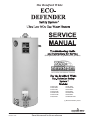
The Bradford White
R
(To be performed ONLY by qualified service providers)
R
U130T*FRN
U130S*FRN
U140T*FRN
U1403T*FRN
U1403S*FRN
U1404T*FRN
U1503*FRN
U150L*FRN
U1504S*FRN
U430T*FRN
U440T*FRN
U4403S*FRN
U4503*FRN
U1XR403S*FRN
(*) Denotes Warranty Years.
Manual 47132A
Save this manual for future reference
The Bradford White
R
Ultra Low NOx Gas Water Heaters
Page
Service Procedure
Introduction
3
---
Gas Control Troubleshooting Chart
5
---
Tools Required for Service
4
---
Burner and Inner Door Gasket Removal, Inspection, Replacement
and Installation
7
ED-I
Thermopile Testing and Replacement
10
ED-II
Pilot Assembly Inspection, Cleaning and Replacement
12
ED-III
Igniter and Electrode Testing and Replacement
13
ED-IV
Gas Control Replacement Thermal Well and Chamber Door Sensor
Testing and Replacement
14
ED-V
Burner Operation Inspection, Cleaning and Replacement
19
ED-VI
Resettable Thermal Switch Testing and Replacement
21
ED-VII
23
ED-VIII
Dip Tube and Anode Inspection and Replacement
24
ED-IX
Generic Parts List
26
---
ScreenLok
R
Flame Arrestor Cleaning
Page 2
2
INTRODUCTION
The Bradford White ECO-DEFENDER Safety System
The Bradford White ECO-DEFENDER Safety System was designed to
resist the ignition of flammable vapors that can occur outside of the water
heater. In addition, the ECO-DEFENDER Safety System is designed to
meet the stringent NOx emissions standards required in the South Coast
Air Quality Management District (SCAQMD) Rule 1121. Use and
installation are nearly identical to previous versions of atmospherically
fired and vented water heaters. A number of exclusive design features are
incorporated in the system that will require additional knowledge on the
part of the qualified service provider. The following information will
instruct service professionals on the function, proper diagnosis and repair
of water heaters employing the Bradford White ECO-DEFENDER Safety
System.
How the Safety System Works
During normal operation, most air for combustion is drawn into the water
heater through the openings in the jacket door. This air travels into the
burner venturi, mixing with the gas jet. This air is then mixed with gas
inside the burner and drawn to the burner screen and is efficiently
combusted producing Ultra Low NOx emissions. Additional air is drawn
through the openings in the jacket. This air travels down and around the
combustion chamber and enters through holes in the bottom of the
corrosion-resistant combustion chamber. The air then travels up through
the oriented flame arrestor plate louvers, where the velocity of the air is
increased and its direction altered. The air then mixes in a normal manner
with the combustion products from the burner.
R
R
In the case where trace amounts of flammable vapors are present in the air
flowing into the combustion chamber and burner venturi, the vapors are
harmlessly ignited by the burner / pilot flame. If flammable vapors are in
sufficient quantity to prevent normal combustion, the burner and pilot
flames are designed to shut down.
Should the flammable vapors continue to the burner, the flame arrestor
plate and burner screen prevent the flames from traveling backwards and
igniting vapors outside of the combustion chamber. This causes the
thermopile to overheat and shuts down the main pilot and burner. The
thermopile powers the intelligent diagnostic control which is capable of
recognizing restricted airflow conditions caused by severe lint, dust and
oil accumulation on the burner screen and arrestor plate. The intelligent
diagnostic control will deactivate the burner and pilot in the unlikely event
of restricted airflow.
Page 3
3
How to Use This Manual
It is intended for this manual to be used by qualified service personal for the primary purpose of
troubleshooting and repair of the Bradford White ECO-DEFENDER Series of water heaters.
The Honeywell WV8860Q Gas Control will display error codes in the event of abnormal operation.
Error codes are listed in the troubleshooting chart beginning on page 5 of this service manual. The
troubleshooting chart will also indicate the probable cause for the error code and direct the service
professional to a service procedure to properly diagnose the abnormal operation.
Contact the Bradford White technical support group immediately if diagnosis can not be made
using the methods described in this service manual.
Manometer:
A liquid “U” tube type or a digital (magna-helic) type can be used. This
device is used to measure gas and/or air pressure and vacuum.
Multi-Meter:
A digital type is strongly recommended. This device is used to measure
electrical values. The meter you select must have the capability to
measure volts AC, volts DC, Amps, micro-amps and ohms.
Electronic Probes:
In some cases, standard multi-meter probes will damage or simply
not be effective to obtain certain voltage and ohm reading. It will be
necessary to have special electronic “pin” type multi-meter probes.
These probes are available at most electronic wholesale outlets.
Thermometer:
Used to measure water temperature. An accurate thermometer is
recommended.
Water Pressure Gage:
Used to measure water supply pressure. Also used to determine tank
pressure by adapting to the drain valve of the heater.
Gas Control Service Tool: BWC part number 239-45991-00. A specialized tool designed to remove
the gas control from gas control thermal well. Available from
your Bradford White parts supplier.
Various Hand Tools:
Pipe wrench, channel locks, open end wrenchs (3/8",7/16",½"),
12" crescent wrench, Allen wrench set, screw drivers (common &
Phillips), ¼" nut driver, pliers (common & needle nose), socket set, side
cutters wire cutters, wire strippers, wire crimpers, torpedo level, small
shop vac, step ladder, flashlight and 5 gallon pail.
Page 4
4
Gas Control Troubleshooting
Observe red LED indicator on
gas control. Error flash codes are
displayed with a three second
pause before repeating. Check
and repair the system as noted in
the troubleshooting table below.
Red LED
Indicator
LED Status
Control Status
Gas valve is operating
normally. Pilot flame
None (LED not on may not be present.
or flashing)
Check for pilot flame
through sight glass and
light if necessary.
If set point knob is in
One flash and
"PILOT" position then
three second
pilot flame is detected.
pause.
Turn set point knob to
desired setting
Set point knob has
been recently turned to
LED on
the "OFF" position.
continuously.
Wait until LED goes out
before attempting to
relight
Two flashes and
three second
pause.
Weak pilot flame
detected. System will
reset when pilot flame
is sufficient.
Three flashes and
three second
pause.
Insufficient water
heating. System will
reset.
Four flashes and
three second
pause.
Excessive tank
temperature. System
must be reset.
Probable Cause
1. Gas valve is
functioning normally
2. Gas valve is not
powered. Light pilot
Service Procedure
If the pilot will not stay lit
replace thermopile, see
page 10. If problem
persists replace gas
valve, see page 16.
Gas valve is powered
and waiting for the set Normal operation. Adjust
point knob to be turned thermostat to desired
to a water temperature temperature level.
setting.
Set point knob was
turned to "OFF"
position.
1. Thermopile failure
2. Unstable pilot.
3. Pilot tube block or
restricted.
4. Resettable thermal
switch has opened.
1. Thermowell sensor
and chamber
temperature sensor out
of calibration.
2. Possible short.
1. Thermowell sensor
out of calibration.
2. Faulty gas valve.
LED will go out and the
control will function
normally when the pilot is
lit.
1. See page 10.
2&3. See page 12.
4. See page 21.
1&2. See pages 14 and
18.
1. See page 14.
2. See page 16.
Page 5
5
Gas Control Troubleshooting
LED Status
Control Status
Probable Cause
Service Procedure
1. Damage to the
Five flashes
thermowell wire.
and three
Thermostat well fault. 2. Thermowell
See page 14.
second
sensor resistance
pause.
out of range.
Chamber door
1. Chamber door
Six flashes
temperature sensor out temperature sensor
and three
of specification.
out of calibration.
See page 18.
second
Possible electrical 2. Possible
pause.
short.
electrical short.
1.Turn gas control knob
Seven flashes
1. Control needs to to "OFF" position and
and three
Gas valve electronic be reset
then follow lighting
second
fault detected.
2. Control is wet or instructions.
pause.
physically damaged 2. Replace gas control,
see page 16.
Eight flashes
False pilot flame
Pilot valve stuck in Replace gas control, see
and three
present.
open position.
page 16.
second pause
Ten flashes Insufficient combustion
Insufficient
and three
air detected. Reset
combustion air.
second pause
system.
Page 6
6
See page 19 and 23.
SERVICE PROCEDURE ED-I
Burner and Inner Door/Gasket Removal,
Inspection, Replacement and
Reinstallation
Inner Door Removal Procedure
Step 1.
Rotate the gas control knob to the “OFF”
position.
Step 2.
Remove outer jacket burner access door
Step 3.
Inner Door Removal.
Gas Control Knob Shown In
“OFF” Position
a) Disconnect chamber door temperature sensor wire harness from the gas valve.
b) Disconnect resettable thermal switch white wire lead (leading from gas valve). Disconnect the red wire
leading from the gas valve from the red thermopile wire.
c) Disconnect main burner feed line (¾” wrench), pilot tube (7/16" wrench) and igniter wire from gas valve.
d) Remove (2) 1/4" hex drive screws from right side inner door.
e) Remove (2) 1/4" drive screws from flange section of inner door.
f) Remove (3) 1/4" drive screws from burner door. The burner door and burner are one-piece.
g) Remove burner and inner door and inspect per step 4.
Chamber Door
Temperature
Sensor
¼” Hex Drive Screws Right
and Left Side Inner Door
¼” Hex Drive Screws at
Flange Area of Inner Door
White Wire Lead
White Thermopile
Wire
Chamber Door
Temperature Sensor
Wire Harness
Feed Line Nut
Pilot Nut
Red Wire Lead
Red Thermopile
Wire
Step 4. Fully inspect burner and inner door gaskets for the following:
>Tears
>Other imperfections that will inhibit proper seal
>Missing Material
>Gasket adhesion to inner door
>Cracks
>Material left on combustion chamber (around opening)
>Dirt or debris
If the gasket is not effected by any of the above, gasket replacement is not required. If replacement is
required, proceed to Inner Door Gasket Replacement Procedure.
Page 7
7
SERVICE PROCEDURE ED-I
Burner and Inner Door/Gasket Removal,
Inspection, Replacement and
Reinstallation
Inner Door Gasket Replacement
Procedure.
WARNING
If the information in these instructions is not
followed exactly, a fire or explosion may result causing
property damage, personal injury or death.
Step 5.
After inspection of inner door as noted in step 4, completely remove gasket and adhesive residue from burner
and left side inner doors as needed.
Step 6.
Use RTV sealant (recommended bead size 1/8") to secure the inner door gasket to the inner door sections
(right & burner). The burner door gasket must be sliced in the location shown on the illustration below in
order to slide the gasket over the burner venturi. Refer to illustration below for proper RTV sealant
application. Note the overlap configuration in the flange area of the inner door. Set the flange section first, this
will help to achieve the proper over lap position.
Installation of Inner Door With Gasket.
Step 7.
Clean any residual gasket residue or other debris
from combustion chamber surface before
installing the inner door/gasket assembly.
Step 8.
Place the burner door into position first. Tighten
the feed line nut to the gas valve. Use the ¼” hex
drive screw without the built-in washer to secure
the right side of the burner door to the chamber.
Use the ¼” hex drive screws with the built-in
washer to secure the left side of the burner door in
place. DO NOT OVER TIGHTEN SCREWS.
Step 9.
Position thermopile wires, pilot tube and igniter wire
against burner door flange gasket.
Page 8
8
WARNING
Stripped fastener connections may allow
for seal breach of inner door. A seal
breach may result in a fire or explosion
causing property damage, personal injury
or death. Do not over tighten screws in
steps 8, 10 and 11.
If a fastener connection is stripped,
contact the manufacturer listed on the
water heater rating plate.
SERVICE PROCEDURE ED-I
Burner and Inner Door/Gasket Removal,
Inspection, Replacement and
Reinstallation
Position Thermopile Wire,
Pilot Tube and Igniter Wire
Step 10.
Firmly place right side inner door flange against the burner door flange and secure with two ¼” drive
screws from step 3e. DO NOT OVER TIGHTEN SCREWS.
Step 11.
Align right side inner door to combustion chamber and verify the fastener holes of the combustion
chamber are aligned with the right side inner door slotted opening. Verify seal integrity around combustion
opening. Secure right side inner door using 1/4” hex drive screws from step 3b. DO NOT OVER TIGHTEN
SCREWS. Verify both burner and right sides of the inner door are properly positioned and sealed against
the combustion chamber.
Secure flange with
¼" drive screws.
Verify threaded hole
alignment with slotted
openings in inner door.
Step 12.
Reconnect lead wires from gas valve to resettable thermal switch (See photo in step 3). Note, the white wire
needs to be connected to the thermal switch and the red wire needs to be connected to the red wire from the
thermopile.
Step 13.
Reconnect the wire harness from the chamber door temperature sensor to the gas valve (See photo in step 3).
Step 14.
Tighten the pilot nut to the gas valve.
Step 15.
Replace outer jacket burner access door.
Step 16.
To resume operation follow the instructions located on the lighting instruction label or the lighting instructions
located in the installation and operation manual.
Page 9
9
SERVICE PROCEDURE ED-II
Thermopile Testing and Replacement
CLOSED CIRCUIT THERMOPILE TESTING (Honeywell Control)
Step 1.
Closed circuit testing is the preferred method for testing thermopile. Following the lighting instruction
label on the heater, proceed to light the pilot and allow to operate for three minutes. If the pilot will not stay
lit, hold the pilot button (rotate the gas control knob to the pilot position, push and hold in) during this test
Step 2.
Using a multimeter capable of measuring millivolts, place one lead of the multi meter on the left side of the
wire harness and place the second lead of the multi meter on the right side of the wire harness.
Step 3.
If meter reads 300 millivolts or higher, the thermopile is OK. If reading is below 300 millivolts,
replace the thermopile. For maximum thermopile life the thermopile should be replaced with a genuine
Honeywell thermopile (BWC P/N 233-47063-00).
Right Side of Wire Harness
Left Side of Wire Harness
OPEN CIRCUIT THERMOPILE TESTING
Step 1.
Disconnect red thermopile wire from wire harness leading to the gas valve. Disconnect the white thermopile
wire from the resettable thermal switch
Step 2.
Using a multimeter capable of measuring millivolts,
connect one lead to the red thermopile wire and one
lead to the white thermopile wire.
Step 3.
Following the lighting instruction label on the heater, proceed to light the pilot and allow to operate for
three minutes. It will be necessary to hold gas control knob down in the “PILOT” position continuously
throughout this test. Any reading over 400 millivolts indicates good thermopile output.
Page 10
10
SERVICE PROCEDURE ED-II
Thermopile Testing and Replacement
THERMOPILE REPLACEMENT
Step 1.
Turn off gas supply to water heater. Rotate gas control knob to the “OFF” position.
Gas Control Knob Shown In
“OFF” Position
Step 2.
Remove outer jacket door.
Step 3.
Remove right side inner door and burner door per SERVICE PROCEDURE RG-I, steps 3a through 3g.
Step 4
Disconnect the red thermopile wire from the wire harness and the white thermopile wire from the resettable
thermal switch. Follow the thermopile leads to the pilot bracket. Disconnect the thermopile from the pilot
bracket (7/16" wrench).
Step 5.
Install new thermopile into pilot bracket and tighten the nut to the pilot bracket (7/16" wrench). Position
thermopile wire against left side inner door flange at its original position. Connect the red thermopile wire to
the red lead from the wire harness. Connect the white thermopile wire to the resettable thermal switch.
Step 6.
Inspect inner door gasket per SERVICE PROCEDURE ED-I, Step 4.
Step 7.
Install right side inner door and burner door per SERVICE PROCEDURE ED-I, Step 7 through Step 16.
Step 8.
To resume operation follow the instructions located on the lighting instruction label or the lighting
instructions located in the installation and operation manual.
Thermopile Position
Page 11
11
SERVICE PROCEDURE ED-III
Pilot Assembly Inspection, Cleaning
and Replacement
PILOT/ELECTRODE ASSEMBLY INSPECTION,
CLEANING AND REPLACEMENT
Gas Control Knob Shown In
“OFF” Position
Step 1.
Turn off gas supply to water heater. Rotate gas
control knob to the “OFF” position.
Step 2.
Remove outer jacket door.
Step 3.
Remove burner and right side of inner door
per SERVICE PROCEDURE ED-I, steps
3a through 3g.
Step 4.
Remove burner assembly from combustion chamber.
Step 5.
Remove pilot/electrode assembly from burner (¼" drive tool)
Step 6.
Inspect pilot for the following:
Chamber Door
Temperature
Sensor
a) Primary air openings for blockage. Must be free from any
debris (dirt, lint, etc).
Feed Line Nut
Pilot Nut
b) Kinks or cracks in the pilot tube. If found,
the pilot must be replaced.
Step 7.
Inspect pilot orifice:
a) Remove 7/16" nut from bottom of pilot assembly.
b) Remove pilot tube and pilot orifice.
Primary Air
Opening
c) inspect pilot orifice for blockage, must be cleaned or replaced.
Pilot Orifice
Step 8.
Install pilot/electrode assembly to burner, secure with screw from step 5.
Step 9.
Install burner and inner door per SERVICE PROCEDURE ED-I, step 4 through 16.
Step 10.
To resume operation follow the instructions located on the lighting instruction label or the lighting instructions
located in the installation and operation manual.
Page 12
12
SERVICE PROCEDURE ED-IV
Igniter and Electrode Testing
and Replacement
IGNITER, ELECTRODE TESTING AND REPLACEMENT
With the pilot not in operation (no pilot flame) you can check the igniter and electrode circuit by viewing pilot
thru the sight glass located on the inner door and observing the spark action.
Step 1.
Remove outer jacket door.
Step 2.
Repeatedly depress the igniter button while viewing the pilot thru the sight glass. If a spark is
present, the circuit is OK. If there is no spark, proceed to step 3.
View spark
Action through
Sight glass
Repeatedly
Depress
Igniter
Step 3
Remove white wire from igniter. Hold the igniter lead from the gas valve to an unpainted surface
such as the feed line or gas valve and depress the igniter. If there is a spark, the igniter is OK,
the pilot is not functioning and must be replaced, see SERVICE PROCEDURE ED-III for pilot
replacement. If no spark is present the igniter is not functioning and the control must be replaced,
see SERVICE PROCEDURE ED-V
Igniter Lead
Page 13
13
SERVICE PROCEDURE ED-V
Gas Control Replacement Thermal
Well and Chamber Door Sensor
Testing and Replacement
Thermal Well Testing
Disconnect thermal
well wire harness
If Control has gone into lockout due to excessive
tank temperature (four flash, 3 second pause) reset
control by rotating gas control knob to “OFF”
position. Then follow lighting instructions and return
gas control knob to desired setpoint.
Observe heater operation. If control
continues to lockout due to
excessive tank temperature,
proceed to thermal well testing to
determine cause.
1
Thermal well testing
Position gas control knob to the
“OFF” position and disconnect
thermal well harness from gas
control.
2
CAUTION
DO NOT use standard multimeter probes for this test.
Doing so will damage connector. Use special pin type
electronic probes or small diameter wire pins inserted
into connector.
Using a multi-meter set to the
Ohms setting, determine the
resistance of thermal well sensor
(see caution photos 1 & 2)
Using a multi-meter set to the ohms setting, insert one meter probe (see caution)
into center wire position of thermal well connector, insert the second probe (see
caution) into either of the outside wire positions (see photo 1).
Alternate the probe on the outside position to the opposite outside wire position
(see photo 2).
Once the thermal well resistance values are known, the water
temperature must also be known to determine if the resistance
values are correct. See page 15 to obtain water temperature.
N
Are thermal well resistance values correct?
Y
Replace gas control
(see page 16)
Page 14
14
Replace thermal well
(see page 16)
SERVICE PROCEDURE ED-V
Gas Control Replacement Thermal
Well and Chamber Door Sensor
Testing and Replacement
WARNING
Stored water may be HOT when performing the following steps in this procedure.
Take necessary precaution to prevent personal injury.
Determine Water Temperature Inside Tank
Note: It is important to understand once the resistance for the thermal well is determined from page 14, water flow
through the heater should not occur. Prior to performing the steps below, turn off the cold water supply to the
water heater. This will prevent cold water flow into the tank affecting the resistance value of thermal well.
Step 1.
Position gas control power switch to “OFF” position.
Step 2.
Draw approximately 4 gallons of water from drain valve into a container and discard. Draw an
additional gallon and immediately measure water temperature using an accurate thermometer. It may
be necessary to open a hot water faucet to allow heater to drain.
Step 3.
Using the chart below, determine correct resistance value for the water temperature from step 2.
Example:
If temperature of water is 84°F, then the resistance through the sensor would be
8449 (see shaded area). NOTE: Sensor resistance increases as the temperature
falls.
Sensor Resistance at Various Temperatures
°F
40
50
60
70
80
90
100
110
120
130
140
150
160
170
180
190
200
0
26109
19906
15314
11884
9299
7333
5827
4663
3758
3048
2488
2043
1688
1402
1170
982
828
1
25400
19383
14925
11592
9078
7165
5697
4562
3679
2986
2439
2004
1656
1376
1150
965
814
2
24712
18876
14548
11308
8862
7000
5570
4464
3602
2925
2391
1966
1625
1351
1129
949
801
3
24045
18383
14180
11032
8653
6839
5446
4368
3527
2866
2344
1928
1595
1327
1110
933
788
In Degrees
4
23399
17905
13823
10763
8449
6683
5326
4274
3453
2808
2298
1891
1566
1303
1090
917
775
F
5
22771
17440
13477
10502
8250
6531
5208
4183
3382
2752
2253
1856
1537
1280
1071
901
762
6
22163
16990
13140
10248
8057
6383
5094
4094
3312
2697
2209
1820
1509
1257
1953
886
749
7
21573
16553
12812
1000
7869
6238
4982
4006
3244
2643
2166
1786
1481
1235
1035
871
737
8
21000
16128
12494
9760
7685
6098
4873
3922
3177
2590
2124
1753
1454
1213
1017
857
725
9
20445
15715
12185
9526
7507
5961
4767
3839
3112
2538
2083
1720
1427
1191
999
842
713
Page 15
15
SERVICE PROCEDURE ED-V
Gas Control Replacement Thermal
Well and Chamber Door Sensor
Testing and Replacement
Gas Control & Thermal Well Removal From Water Heater
Gas Control
Step 1.
Turn the gas control knob to the
“OFF” position.
Step 2.
Drain heater to a point below the gas
control level.
Step 3.
Turn off gas supply to water heater and
disconnect gas piping from gas control.
Step 4.
Disconnect wire harnesses and burner assembly
from gas control.
Step 5.
Remove gas control & thermal well by rotating flats of Thermal Well counter clockwise (1-5/16"wrench).
Thermal
Well
Gas Control Removal From Thermal Well
Follow the steps below allows removal gas control from thermal well without
removing thermal well from tank.
Step 1.
Turn the gas control knob to the “OFF” position.
Step 2.
Turn off gas supply to water heater and disconnect gas piping from gas control.
Step 3.
Disconnect wire harnesses & burner assembly from gas control.
Step 4.
Using gas control service tool (239-45991-00) available from your BWC parts supplier, Insert tool into
back of gas control (see photos below)
View from back of
control for clarity
Insert tool from
back of control
Step 5.
Service tool shown
inserted in to back
of control
Pivot tool towards heater as far as possible (see photo below). Lift straight up on gas control. The
control should move about 1/8". Hold control in position and remove tool. Lift straight up on control to
remove completely from Thermal Well.
With service tool inserted, pivot tool back towards
heater as far as possible. Lift straight up on control,
control will move 1/8". Remove tool and continue to lift
straight up on control to remove from Thermal Well.
Page 16
16
SERVICE PROCEDURE ED-V
Gas Control Replacement Thermal
Well and Chamber Door Sensor
Testing and Replacement
Gas Control Assembly to Thermal Well
Step 1.
Install threaded end of thermal well into tank. Be sure
thermal well flange is positioned as shown in photo 3
for proper control alignment.
Step 2.
Route wire leads back into relief opening.
(see photo 3).
Step 3.
Align slots located on thermal well flange with tabs
located on back of gas control (see photos 3 & 4).
3
Route wires
through relief
opening
Thermal well
flange slots
Step 4.
Carefully push control back onto thermal well flange
as far as possible towards water heater. Slide control
down to lock into position.
Step 5.
Install burner and connect pilot and feed line to gas
control.
4
Gas control Tabs
Thermopile
Wire Harness
Connection
Igniter Connection
Step 6.
Reconnect wire harnesses and igniter
wire to gas control per the illustration to
the left.
Step 7.
Reconnect gas piping to gas control.
Restore gas supply and check for gas
leaks.
Step 8.
To resume operation, follow the
instruction located on the lighting
instruction label or the lighting instruction
located in the installation and operation
manual.
3 Pin Thermal Well
Connection
Chamber Door
Temperature
Sensor
Page 17
17
SERVICE PROCEDURE ED-V
Gas Control Replacement Thermal
Well and Chamber Door Sensor
Testing and Replacement
CHAMBER SENSOR TESTING
Step 1.
Turn the gas control knob to the “OFF” position
Step 2.
Disconnect the chamber sensor wire harness from
the gas valve.
Step 3.
Remove the chamber door temperature sensor
from the right side inner door (Phillips screw
driver).
Step 4.
Make sure that the ring terminal of the chamber
door temperature sensor is not touching any
surface. Using a multi-meter set to the ohms
setting, insert one meter probe (see caution) into
each of the wire positions (see photo 5).
Step 5.
Measure the ambient air temperature near the
sensor. Compare the ambient temperature
range to the expected resistance range on the
chart below. Note that resistance increases as
temperature decreases.
5
Gas Control Knob Shown In
“OFF” Position
Chamber Door
Temperature Sensor
Wire Harness
Sensor Resistance at Various Temperatures
CAUTION
DO NOT use standard multimeter probes for this test.
Doing so will damage connector. Use special pin type
electronic probes or small diameter wire pins inserted
into connector.
Temperature Range (o F) Resistance Range (kOhms)
41-50
279-175
50-59
219-139
59-68
173-112
68-77
137-90
77-86
110-72
86-104
89-59
104-113
73-48
113-122
60-39
122-131
49-32
Step 6.
Replace the chamber door temperature sensor if it it out of specification.
Step 7.
Secure the chamber door temperature sensor to the right side inner door using the screw from step 3.
Step 8.
Connect the chamber door temperature sensor wire harness to the gas valve.
Step 9.
To resume operation, follow the instruction located on the lighting instruction label or the lighting
instruction located in the installation and operation manual.
Page 18
18
SERVICE PROCEDURE ED-VI
Burner Operation Inspection,
Cleaning and Replacement
MAIN BURNER: Inspection,
Cleaning and Replacement
At periodic intervals (not more then 6 months) a visual inspection should be made of the main burner for proper operation
and to insure no debris is accumulating.
Main burner should light smoothly from pilot and burn with a blue flame with a minimum of yellow tips. After 5 minutes
of operation the burner screen will become radiant and the flame will soften and turn orange. If the burner screen does not
become radiant after 5 minutes of operation it must be cleaned (see burner cleaning procedure below).
Main burner must be free from any debris accumulation that may effect burner operation (see burner cleaning procedure
below).
DANGER
Under no circumstances shall flammable materials be used or stored in the vicinity of the water heater. With
the inner door removed the Bradford White Defender Safety System will be inactivated. If flammable vapors
are present, a fire or explosion may result causing property damage, personal injury or death.
WARNING
Inner door and burner components may be HOT when performing this operation. Take
necessary precaution to prevent personal injury.
BURNER CLEANING
Step 1.
Remove burner and inner door assembly per SERVICE PROCEDURE ED-I, steps 1 through 3g.
Step 2.
Remove manifold mount from burner inner door by removing (2) ¼” hex drive screws.
Step 3.
Thoroughly inspect burner screen and burner venturi and remove any loose debris accumulation. Inspect
burner screen for any openings larger than the normal screen openings.
Step 4.
Use compressed air and/or a vacuum to remove any scale or other debris accumulation from the burner screen
and venturi.
Burner Screen
¼” Hex Drive Screws
Burner Venturi
Page 19
19
SERVICE PROCEDURE ED-VI
Burner Operation Inspection,
Cleaning and Replacement
BURNER CLEANING (Cont.)
Step 5.
Disconnect (unscrew) manifold mount from feed line. Use a stiff
brush, compressed air and/or shop vacuum to remove any debris
build up from the manifold mount.
Step 6.
Remove main burner orifice from feed line (3/8" wrench). Inspect and
clean if necessary
Step 7.
Remove pilot assembly, refer to SERVICE PROCEDURE ED-III for cleaning and inspection.
Step 8.
Reassemble burner.
Step 9.
Inspect combustion chamber area of heater prior to reinstallation of burner assembly. If cleaning is required,
refer to SERVICE PROCEDURE ED-VIII
Step 10.
Reinstall burner and inner door per SERVICE PROCEDURE ED-I, steps 4 through 16.
Step 11.
To resume operation, follow the instructions located on the lighting instruction label or the lighting
instructions located in the installation and operation manual.
Page 20
20
SERVICE PROCEDURE ED-VII
Resettable Thermal Switch
Testing and Replacement
RESETTABLE THERMAL SWITCH CONTINUITY TESTING
Step 1.
Remove outer jacket door.
Step 2.
Disconnect white wire leads from resettable thermal switch.
Step 3.
Using a multimeter capable of measuring continuity (Ohms),
place one probe of meter on one of the brass connection tabs of
the resettable thermal switch, and the remaining probe on the
other connection tab.
Step 4.
If continuity is indicated, the switch is closed, allowing millivolt current to pass.
Step 5.
If continuity is not indicated, the switch is open, possibly due to an over heating condition. The switch is
designed to open at predetermined temperatures. An open switch can be reset by depressing the red colored
button located at the center of the switch. The overheating condition must be determined prior to putting the
water heater back in service.
PROBABLE CAUSE FOR RESETTABLE THERMAL SWITCH ACTIVATION
PROBABLE CAUSE
CORRECTIVE ACTION
1. Inspect burner per SERVICE PROCEDURE
ED-VI
Burner Failure
Weak switch or switch
out of calibration.
Flammable vapor incident
2. Replace burner per SERVICE PROCEDURE
ED-VI
1. Replace resettable thermal switch
1. Replace water heater.
Page 21
21
SERVICE PROCEDURE ED-VII
Resettable Thermal Switch
Testing and Replacement
RESETTABLE THERMAL SWITCH REPLACEMENT
Step 1.
Rotate gas control knob to the “OFF” position.
Gas Control Knob Shown In
“OFF” Position
Step 2.
Remove outer jacket door.
Step 3.
Disconnect wire leads from resettable thermal switch.
Step 4.
Remove (2) ¼” hex drive screws from the manifold mount.
Step 5.
Bend the flexible feed line so the resettable thermal switch is easily
accessible.
Step 6.
Remove resettable thermal switch from manifold mount (Phillips
screw driver).
Manifold Mount
Step 7.
Place new resettable thermal switch in place. Be sure contact surface of resettable thermal switch and
manifold mount are free of any debris. Secure resettable thermal switch into place using screws from step 6.
DO NOT OVER TIGHTEN SCREWS.
Step 8.
Bend flexible feed line back in place and secure the manifold mount using the screws from step 4.
Step 9.
Reconnect wire leads from gas valve and thermopile to resettable thermal switch.
Note: Wire termination are interchangeable with either resettable thermal switch connection.
Step 10.
Replace outer jacket door.
Step 11.
To resume operation follow the instructions located on the lighting instruction label or the lighting instruction
located in the installation and operation manual.
Page 22
22
SERVICE PROCEDURE ED-VIII
ScreenLok Flame Arrestor Cleaning
ScreenLok Flame Arrestor Cleaning
Step 1.
Rotate gas control knob to the “OFF” position.
Gas Control Knob Shown In
“OFF” Position
Step 2.
Remove outer jacket door.
Step 3.
Remove burner and inner door per SERVICE PROCEDURE
ED-I, step 3a through 3g.
Step 4.
Clean ScreenLok Flame Arrestor using stiff brush, compressed air and/or shop vacuum to remove any scale or
other debris accumulation. It is only necessary to clean the ScreenLok Flame Arrestor in the areas that are not
covered by the secondary air restrictor plate. Using a soft brush, clear jacket openings of any dirt, dust,
restrictions or other obstructions.
Step 5.
Remove any debris from burner assembly per SERVICE PROCEDURE ED-VI and reinstall burner assembly
into combustion chamber.
Step 8
Reinstall burner and inner door per SERVICE PROCEDURE ED-I, steps 4 through 16.
Step 9.
To resume operation follow the instructions located on the lighting instruction label or the lighting instruction
located in the installation and operation manual.
Page 23
23
SERVICE PROCEDURE ED-IX
Dip Tube and Anode
Inspection and Replacement
DIP TUBE INSPECTION AND REPLACEMENT
WARNING
Water Heater components and stored water may be HOT when performing the following
steps in this procedure. Take necessary precaution to prevent personal injury.
Step 1.
Rotate gas control knob to the “OFF” position.
Gas Control Knob Shown In
“OFF” Position
Step 2.
Turn off cold water supply to water heater. Connect hose to drain spigot of water heater and route to an open
drain. Open a nearby hot water faucet to vent heater for draining. Open drain spigot of water heater and
allow water heater to drain to a point below the inlet connection nipple.
Step 3.
Disconnect inlet nipple from plumbing system.
Step 4
With an appropriate wrench, remove inlet nipple/dip tube from the water heater. Use caution not to damage
pipe threads.
Step 5.
Visually Inspect inlet nipple/dip tube. Inlet nipple/dip tube should be free of cracks and any blockage.
Hydro-jets located near the bottom of the dip tube should be open and free of any blockage.
Anti-siphon hole located approximately 6" from the bottom of nipple, should be free of any blockage.
Any damage such as cracks, restriction due to deformation or unintentional holes are not field repairable
and the inlet nipple/dip tube must be replaced.
Step 6.
Upon completion of inspection or subsequent replacement, reinstall inlet nipple/dip tube into heater. Connect
nipple to plumbing system, resume water supply and refill water heater with water.
Step 7.
To resume operation follow the instructions located on the lighting instruction label or the lighting instructions
located in the installation and operation manual.
Page 24
24
SERVICE PROCEDURE ED-IX
Dip Tube and Anode
Inspection and Replacement
ANODE INSPECTION AND REPLACEMENT
WARNING
Heater components and stored water may be HOT when performing the following steps in
this procedure. Take necessary precaution to prevent personal injury.
Step 1.
Turn off water supply to water heater. Rotate gas control knob to the “OFF” position.
Gas Control Knob Shown In
“OFF” Position
Step 2.
Turn off cold water supply to heater. Connect hose to drain spigot of water heater and route to an open drain.
Open a nearby hot water faucet to vent heater for draining. Open drain spigot of hot water heater and allow
heater to drain to a point below the outlet connection nipple.
Step 3.
Disconnect outlet nipple from plumbing system.
Step 4
With an appropriate wrench, remove outlet nipple/anode from the water heater. Use caution not to damage
pipe threads.
Step 5.
Visually Inspect outlet nipple/anode. Outlet nipple/anode should show signs of depletion, this is normal.
If depletion is ½ of the original anode diameter (approximately ¾” diameter), replacement is recommended.
If any of the steel core of the anode is exposed, replacement is recommended.
Step 6.
Upon completion of inspection or subsequent replacement, reinstall outlet nipple/anode into heater. Connect
nipple to plumbing system, resume water supply and refill heater with water.
Step 7.
To resume operation, follow the instructions located on the lighting instruction label or the lighting
instructions located in the installation and operation manual.
Page 25
25
1
2
3
4
5
6
7
8
9
10
11
12
13
14
15
16
17
18
19
20
21
22
23
24
25
26
27
28
29
30
31
32
Flue Baffle
Hot Water Outlet/Anode
Cold Water Inlet Tube
T&P Relief Valve
Thermal Well
Brass Drain Valve
Gas Valve
Main Burner Orifice
Heat Trap Inlet
Heat Trap Outlet
Outer Door
Draft Diverter
Complete Burner Assembly
RN Burner and Door
Flexible Gas Feed Line
Pilot Assembly
Page 26
26
Screw #8-18 x ½ Hex Washer Head
Resettable Thermal Switch
Screw #6-20 x 3/8 PHCR
Screw #8-18 x ¾ Hex Washer Head
Manifold Mount
Complete Right Side Inner Door
Resistance Temperate Detector (RTD)
Screw #10-12 x ¾ Hex Washer Head
¾ NPT Tank Plug (XR Models)
Wire Tie
ASSE Approved Mixing Valve (Optional)
Thermopile
Inner Door Gasket Set
Pilot Orifice
Kit-Heat Trap Insert
Intermediate Gas Valve Harness
27
Email
[email protected]
[email protected]
www.bradfordwhite.com