1
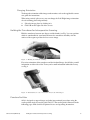
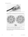
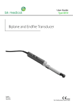
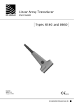
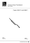
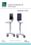
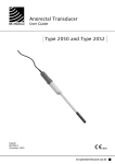
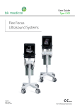
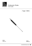
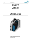
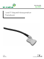
User Guide
Type 8824
I and T Shaped Intraoperative
Transducer
English
BB 1823-C
August 2012
For Professional Users Only
WORLD HEADQUARTERS
Mileparken 34
DK-2730 Herlev
Denmark
Tel.:+45 44528100 / Fax:+45 44528199
www.bkmed.com
Email: [email protected]
If you have comments about the user documentation, please write to us at the email address above.
We would like to hear from you.
BK Medical Customer Satisfaction
Input from our customers helps us improve our products and services. As part of our customer
satisfaction program, we contact a sample of our customers a few months after they receive their orders.
If you receive an email message from us asking for your feedback, we hope you will be willing to
answer some questions about your experience buying and using our products. Your opinions are
important to us. You are of course always welcome to contact us via your BK Medical representative or
by contacting us directly.
© 2012 BK Medical
Information in this document may be subject to change without notice.
Contents
Introduction . . . . . . . . . . . . . . . . . . . . . . . . . . . . . . . . . . . . . . . . . . . . . . . . . . . . . . 5
Indications for Use . . . . . . . . . . . . . . . . . . . . . . . . . . . . . . . . . . . . . . . . . . . . . 5
Scanning Planes . . . . . . . . . . . . . . . . . . . . . . . . . . . . . . . . . . . . . . . . . . . . . . . 5
General Information . . . . . . . . . . . . . . . . . . . . . . . . . . . . . . . . . . . . . . . . . . . . . . . 6
Service and Repair . . . . . . . . . . . . . . . . . . . . . . . . . . . . . . . . . . . . . . . . . . . . . 7
Caring for the Transducer. . . . . . . . . . . . . . . . . . . . . . . . . . . . . . . . . . . . . . . . 7
Cleaning and Disinfection . . . . . . . . . . . . . . . . . . . . . . . . . . . . . . . . . . . . . . . . . . . 7
Starting Scanning. . . . . . . . . . . . . . . . . . . . . . . . . . . . . . . . . . . . . . . . . . . . . . . . . . 7
Connecting the Transducer. . . . . . . . . . . . . . . . . . . . . . . . . . . . . . . . . . . . . . . 8
Changing Frequency. . . . . . . . . . . . . . . . . . . . . . . . . . . . . . . . . . . . . . . . . . . . 8
Using a Transducer Cover . . . . . . . . . . . . . . . . . . . . . . . . . . . . . . . . . . . . . . . 8
Changing Orientation . . . . . . . . . . . . . . . . . . . . . . . . . . . . . . . . . . . . . . . . . . . 9
Holding the Transducer for Intraoperative Scanning . . . . . . . . . . . . . . . . . . . . . . 9
Puncture Facilities . . . . . . . . . . . . . . . . . . . . . . . . . . . . . . . . . . . . . . . . . . . . . . . . . 9
Needle guide UA1337 . . . . . . . . . . . . . . . . . . . . . . . . . . . . . . . . . . . . . . . . . 10
Assembling the Needle Guide and Mounting it on the Transducer . . . . . . . 12
Releasing the Needle During Biopsy . . . . . . . . . . . . . . . . . . . . . . . . . . . . . . 13
Performing Puncture and Biopsy. . . . . . . . . . . . . . . . . . . . . . . . . . . . . . . . . . . . . 13
Cleaning after Puncture and Biopsy . . . . . . . . . . . . . . . . . . . . . . . . . . . . . . . 14
Disposal . . . . . . . . . . . . . . . . . . . . . . . . . . . . . . . . . . . . . . . . . . . . . . . . . . . . . . . . 14
3
4
Introduction
This is the user guide for I and T Shaped Intraoperative Transducer Type 8824 and
must be used together with Care, Cleaning & Safety which contains important safety
information.
T array
I array
Figure 1. I and T Shaped Intraoperative Transducer Type 8824 seen from different angles
Indications for Use
The 8824 is a simultaneous biplane transducer for ultrasound-guided interventional
procedures.
Needle guide UA1337 provides guidance for needles or other interventional devices
during an ultrasound-guided procedure. It positions the needle relative to the
transducer, so that the needle image is in a specified position in the ultrasound image
during procedures that require precise needle placement or biopsy.
WARNING
Do not use the transducer for applications where it may come in direct conductive contact
with the patient’s heart.
FDA WARNING for the United States of America
8824 is not for fetal use.
Scanning Planes
The transducer contains two convex arrays in the shape of a T. Each array has a single
scanning plane and the two scanning planes intersect orthogonally, see Fig. 2 The
two scanning planes can be viewed separately or simultaneously, thus giving a better
orientation when viewing suspicious lesions.
8824 User Guide (BB1823-C)
Introduction
5
Simultaneous Biplane Scanning
The transducer can transmit transverse (T) and sagittal (S) images simultaneously.
When you press the scanner’s Split button, simultaneous live transmission is
automatically activated. On the screen, this is indicated by a green dot in front of the
Simultan button.
Click on Simultan to toggle simultaneous live transmission on or off. Alternatively,
a long press on the scanner’s Split button turns simultaneous live transmission off.
When simultaneous transmission is off, you can change which plane is active and
which is frozen by pressing the Split button or by placing the cursor on the image
you want to be active and pressing the Select button.
Transverse plane
(T array)
Sagittal plane
(I array)
Figure 2. Scanning planes of the 8824
General Information
Product specifications for this transducer can be found in the Product Data sheet that
accompanies this user guide.
Acoustic output data and data about EMC (electromagnetic compatibility) for this
transducer are on the Technical Data CD that accompanies this user guide. A full
explanation of acoustic output data is given in your scanner user guide.
WARNING
If at any time the scanner malfunctions, or the image is severely distorted or degraded, or
you suspect in any way that the scanner is not functioning correctly:
• Remove all transducers from contact with the patient.
• Turn off the scanner. Unplug the scanner from the wall and make sure it cannot be
used until it has been checked.
• Do not remove the scanner cover.
• Contact your BK Medical representative or hospital technician.
6
August 2012
8824 User Guide (BB1823-C)
WARNING
Always keep the exposure level (the acoustic output level and the exposure time) as low
as possible.
Service and Repair
WARNING
Service and repair of BK Medical electromedical equipment must be carried out only by
the manufacturer or its authorized representatives. BK Medical reserves the right to
disclaim all responsibility, including but not limited to responsibility for the operating
safety, reliability and performance of equipment serviced or repaired by other parties.
After service or repairs have been carried out, a qualified electrical engineer or hospital
technician should verify the safety of all equipment.
Caring for the Transducer
The transducer may be damaged during use or processing, so it must be checked
before use for cracks or irregularities in the surface. It should also be checked
thoroughly once a month following the procedure in Care, Cleaning & Safety.
Cleaning and Disinfection
To ensure the best results when using BK Medical equipment, it is important to
maintain a strict cleaning routine.
Full details of cleaning and disinfection procedures can be found in Care, Cleaning
& Safety that accompanies this user guide. A list of disinfectants and disinfection
methods that the transducer can withstand are listed in the Product Data sheet.
Sterile covers are available. See the Product Data sheet for more information.
WARNING
Users of this equipment have an obligation and responsibility to provide the highest
degree of infection control possible to patients, co-workers and themselves. To avoid cross
contamination, follow all infection control policies for personnel and equipment
established for your office, department or hospital.
Starting Scanning
All equipment must be cleaned and disinfected before use.
8824 User Guide (BB1823-C)
Cleaning and Disinfection
7
Connecting the Transducer
WARNING
Keep all plugs and sockets absolutely dry at all times.
The transducer is connected to the scanner using the array Transducer Socket on the
scanner. To connect, the transducer plug’s locking lever should first be in a horizontal
position. Align the plug to the scanner socket and insert securely. Turn the locking
lever clockwise to lock in place.
When connected the transducer complies with Type BF requirements of EN60601-1
(IEC 60601-1).
Changing Frequency
The Multi-Frequency Imaging (MFI) facility enables you to select the scanning
frequency. See the applicable scanner user guide for instructions. The selected
frequency is displayed at the top of the screen.
Using a Transducer Cover
The transducer should be enclosed in a transducer cover or a standard condom. See
the Product Data sheet for a list of available transducer covers.
Note: Sterile, disposable sheaths are recommended for intraoperative use. In the
United States of America, it is recommended that probe sheaths have been marketcleared. In Canada, use only licensed probe sheaths.
WARNING
Because of reports of severe allergic reactions to medical devices containing latex (natural
rubber), FDA is advising health-care professionals to identify their latex-sensitive patients
and be prepared to treat allergic reactions promptly.
Note: For Intraoperative Applications
Apply sterile gel to the tip of the transducer or fill the cover with 1 to 2ml of sterile
water. This improves the screen images by preventing image artifacts caused by air
bubbles.
Pull the transducer cover over the transducer.
WARNING
Use only water-soluble agents or gels. Petroleum or mineral oil-based materials may harm
the cover material.
8
August 2012
8824 User Guide (BB1823-C)
Changing Orientation
To change the orientation of the image on the monitor, refer to the applicable scanner
user guide for instructions.
When using vertical split screen, you can change the Left / Right image orientation
of each scanning plane independently:
1 Select the image plane by clicking in it.
2 Click L/R on the right side of the screen.
Holding the Transducer for Intraoperative Scanning
Hold the transducer between two fingers and the thumb (see Fig. 3) or any position
which is comfortable for your hand and move the transducer smoothly over the
surface of the organ to produce the best screen image.
Figure 3. Holding the 8824 for scanning
For easier orientation of the transducer and for freehand biopsy, the 8824 has a small
indentation on either side of the T array and a small indentation behind the I array,
see Fig. 4
Figure 4. Indentations for easier orientation and for freehand biopsy
Puncture Facilities
8824 is designed to support biopsy and other interventional procedures using the
sterile-packed single-use needle guide UA1337. The needle guide is illustrated in the
following pages with a brief description of its use and operating instructions.
8824 User Guide (BB1823-C)
Holding the Transducer for Intraoperative Scanning
9
Needle guide UA1337
Figure 5. Needle guide UA1337 with free-angle insert mounted on the 8824 (here shown without cover)
Needle guide UA1337 is supplied together with two needle guide insert palettes.
Each palette contains a set of 9 needle guide inserts, one 3-angle and one free-angle.
Figure 6. Two needle guide palettes supplied together with needle guide UA1337
The 3-angle inserts each contain three channels. These channels allow the needle to
be positioned at 10°, 30° or 50° to the image axis of the 8824.
The free-angle inserts are slotted to allow the positioning of the needle at any angle
between 10° and 50° to the image axis of the 8824 while making sure that the needle
follows the plane of the image.
10
August 2012
8824 User Guide (BB1823-C)
The puncture line pattern is shown in Fig. 7 The distance between the guide channel
of the puncture attachment to the first dot on the scan image puncture line is 1215mm depending on which angle is chosen. The distance between the dots is 5mm.
Figure 7. Puncture lines using the 3-angle inserts
Sterile needle guide UA1337
Needle guide UA1337 and the needle guide insert palettes are supplied sterile in peel
packs and are for single-use only. Contents are only sterile if the package is intact.
The needle guide, the inserts and both palettes must be discarded after use.
WARNING
Disposable components are packaged sterile and are intended for single-use only.
• Do not use if:
• integrity of packaging is violated
• expiration date has passed
• package label is missing
The sterile-packed needle guides must be stored at a temperature range from +15°C
(+57°F) to +25°C (+77°F) and at a storage humidity of 30% to 80%.
WARNING
Sterile-packed components must be stored in a safe environment and kept out of direct
sunlight. Large temperature changes during storage may cause condensation and violate
the integrity of the packaging.
Please refer to Care, Cleaning and Safety for an example of how to open a sterilepacked product.
8824 User Guide (BB1823-C)
Puncture Facilities
11
WARNING
For contaminated disposals such as transducer covers or needle guides, follow disposal
control policies established for your office, department or hospital.
Assembling the Needle Guide and Mounting it on the Transducer
Apply a small amount of scanning gel to the tip of the transducer and carefully cover
the transducer with a sterile cover (for readability, the transducer here is shown
without transducer cover).
Select the required needle guide insert by
breaking it off the palette.
Find the wedge shaped channel in the needle
guide and slide the insert into the channel in the
needle guide from above until it clicks into place
and aligns with the needle guide.
Hold the needle guide in your right hand with
the lip at the bottom and pointing away from
you.
Align the two grooves on the transducer with the
two ridges on the needle guide. The lip of the
needle guide should fit snugly underneath the
transducer housing.
Carefully smooth and stretch the transducer
cover along the face of the array while applying
pressure until the needle guide clicks into place
over the end of the transducer.
Caution
Ensure the needle guide is positioned correctly.
Carefully insert the needle into the needle
channel.
Caution
Do not let it scrape the inside of the needle
channel.
12
August 2012
8824 User Guide (BB1823-C)
Releasing the Needle During Biopsy
You can release the needle during biopsy so that the needle guide and transducer can
be removed from the patient, leaving only the needle in place.
Hold the transducer with your left hand. With your right hand,
carefully push the needle guide insert sideways until it opens up.
Carefully move the transducer and needle guide away from the
needle.
WARNING
If the needle guide is detached from the transducer during interventional procedures,
cover the transducer with a new transducer cover before reattaching the needle guide.
Performing Puncture and Biopsy
WARNING
It is essential for the patient’s safety that only the correct puncture attachments, as
described in this guide, are used. Never use unauthorized combinations of transducers
and puncture attachments or other manufacturers puncture attachments.
Before beginning a puncture or biopsy procedure, always check that the type number of
the transducer and the type number or description of the puncture attachment match
exactly those displayed on the scanner monitor.
WARNING
The puncture line on the scan image is an indication of the expected needle path. The
needle tip echo should be monitored at all times so any deviation from the desired path
can be corrected. You must take extra care when taking a free-angle biopsy because the
expected needle path is not shown.
Cover the transducer with a sterile transducer cover.
If the transducer cover is damaged when attaching the puncture attachment, replace
it with a new cover.
Note: Sterile, disposable sheaths are recommended for intraoperative use; and in the
U.S.A. it is recommended that probe sheaths have been market-cleared. In Canada,
use only licensed probe sheaths.
See the Product Data sheet for a list of available transducer covers.
Press the scanner Puncture or Biopsy control button to superimpose a puncture
line on the scan image.
8824 User Guide (BB1823-C)
Performing Puncture and Biopsy
13
If more than one puncture line is available, refer to the applicable scanner user guide
for instructions on how to change which one appears.
Move the transducer until the puncture line transects the target. Insert the needle and
monitor it as it moves along the puncture line to the target. The needle tip echo will
be seen as a bright dot on the screen.
WARNING
If the needle guide is detached from the transducer during interventional procedures,
cover the transducer with a new transducer cover.
To remove the puncture line from the scan image, refer to the applicable scanner user
guide for instructions.
WARNING
When performing a biopsy, always make sure that the needle is fully drawn back inside the
needle guide before moving the probe.
Cleaning after Puncture and Biopsy
If biological materials are allowed to dry on the transducer, disinfection and
sterilization processes may not be effective. Therefore, you must clean the transducer
immediately after use.
Use a suitable brush to make sure that biological material and gel are removed from
all grooves. See Care, Cleaning & Safety for cleaning instructions.
Disposal
When the transducer is scrapped at the end of its life, national rules for the relevant
material in each individual land must be followed. Within the EU, when you discard
the transducer, you must send it to appropriate facilities for recovery and recycling.
See the applicable scanner user guide for further details.
WARNING
For contaminated disposals such as transducer covers or needle guides, follow disposal
control policies established for your office, department or hospital.
14
August 2012
8824 User Guide (BB1823-C)