1
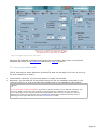
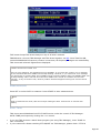
Welcome to TRX-Manager V5 !
Welcome to TRX-Manager, an interactive software for HAM
Radio Operators!
TRX-manager supports almost all the functions of more than 80 commercial transceivers as
well as many accessories (rotators, amplifiers, antennas, keyers, wattmeters...) fully
integrated in a comprehensive package for Radio Amateurs. TRX-Manager implements all these
functions in conjunction with very fast monitoring and easier, more effective SW Listening, DX
Spotting, Logging, Award tracking, Satellite, Rotator control and much more... In addition it
can even operate simultaneously with several other programs including PDA's LOGic logging
program. A control of a remote HF station by packet, Internet or a LAN is also provided along
with many other original features...
If you are impatient to use the program, please see first:
Features map
Getting started
On line-help
But please take time to learn more about all the TRX-Manager's features:
Main Transceiver
Large digital display of the transmitted and received frequencies
Animated VFO knob
S-meter with memory
Joystick control
Easy and quick operation in split and QSX,
Automatic mode and filter switching
Extended control (if supported): Volume, DSP, Keyer...
Transverter option
Remote control of a rig via Packet or Telnet (standard or real)
Remote control using a Web Server
Memory channels management
Graphic band scope for band activity checking
Advanced functions
Keyboard shortcuts
Compact and comprehensive display, DX Bar
Control of up to 3 Sub-Transceivers
Programmable Band Decoder (LPT or COM Port)
Support for SO4R (Single Operator Four Radios) operation
PTT Switching using an external line
Page 1
Quick Memories
Programmable Band Plan
Drag and drop of frequencies between windows
OLE Link, compatibility with LOGic, Swisslog
High precision S-Meter
Macro commands
Synchro for SteppIR beam, ACOM2000 amplifiers, third party program and other controllers
via RS-232,
Linear-Reminder for manual linear amplifier (or antenna tuner)
Support for CW Skimmer
Support for digital Wattmeter
TRX-Pan a Spectrum Analyser for SDR
Short wave listening
Data base for Short Wave Listening
Automatic identification of stations
Sound Recorder
DXing
Web Cluster interface (Internet)
Data terminal (Packet Telnet)
DX Cluster interface, sound announcement
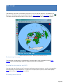
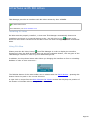
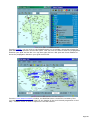
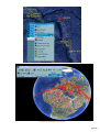
DX Map (Plot spots & NCDXF Beacons), interface with DX Atlas and Google Earth
HF Propagation predictor
Automatic DX Tracking
Rotator control
Satellite Interface
CW Interfacevia Serial or LPT Port, Winkey or CAT Interface
Support for WOTA
Intuitive logging, Awards tracking
Log-book with advanced Import/Export utility
Logbook's Explorer
Comprehensive DXCC information
Prefix database editing (customization, 11m possible)
Real-time tracking of the DXCC IOTAWAZ WAS and VUCC awards
Support for the DDFM/DPF awards
Support possible for other awards
Advanced searches using the SQL language
QSL labels printing
Compatibility with QRZCallbook and HAMCall CD-Roms
Automatic look-up of the FCC License records and GoList QSL Manager database
Contest mode
Callsign look-up via the Internet
Support for the LogBook of The World
Link with LOGic
Graphic interface
Multi language interface (French/English/Spanish/Swedish/German/Polish)
Configurable Tool Bar (Office type) and Sessions
Comprehensive on line help
Internet browser, Quick EMailer
Screen saver and desktop background
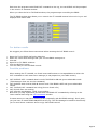
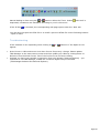
Specifications
Page 2
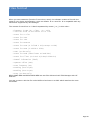
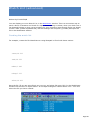
The software runs under any 32 bits or 64 bits version of Windows (Except NT3.51) and
supports the following transceivers defined as Main transceiver:
YAESU
FT-212 FT-412 FT-736 FT-450 FT-747 FT-757GX FT-757GXII FT-767GX FT-817
FT-840 FT-847 FT-857 FT-890 FT-897 FT-900 FT-920 FT-980 FT-990 FT1000MP
/MKV FT1000D FT-990 and FT-1000 ROM 1.2 FRG-100 FT-100 FRG-9600 VR-5000
FTDX-1200 FT-2000 FTDX3000 FTDX5000 FTDX9000
KENWOOD
R-5000 TS-440 TS-450 TS-480 TS-570 TS-590S TS-590SG TS-680 TS-690 TS-711
TS-790 TS-811 TS-850 TS-870 TS-940 TS-950 TS-990 TS-2000
ICOM
IC-703 IC-706MKII IC-706MKIIG IC-718 IC-725/6 IC-735 IC-746 IC-746PRO
IC-7400 IC-7410 IC-751 IC-751A IC-756 IC-756PRO/PRO2/PRO3 IC-765 IC-271
IC-471 IC-275 IC-475 IC-775 IC-781 IC-820/821 IC-910 IC-9100 IC-970 IC-R75
IC-R7000 IC-R7100 IC-R8500 IC-R9000 IC-7000 IC-7100 IC-7200 IC-7600
IC-7700 IC-7800 IC-PCR1000
TENTEC
Omni-VI Omni-VI+ Omni-VII RX320 Argonaut-V Jupiter Eagle Argonaut-VI
JST
NRD-535 NRD-545 JST-145 JST-245
ALINCO
DX-77
ELECRAFT
K2 K3 KX3
Other brands
CODAN NGT RACAL 6790
OMNI-RIG's Library (by VE3NEA See List of supported rigs)
JUMA TRX2
Only the following Transceivers are supported as Sub-Transceivers:
All ICOM, Kenwood and Elecraft transceivers, Yaesu FT-450 FT-736 FT-840 FT- 890
FT-900 FT-950 FT-990 F-1000D FT-1000MP FT-920 FT-817 FT-847 FT-857 FT-897
VR5000 FTDX1200 FT-2000 FTDX3000 FTDX5000 FTDX9000 FT-450 NRD535/545
RX320 ARGONAUT JUPITER ICPCR1000 CODAN RACAL OMNIRIG EAGLE
Please note some of the above functions do not run with all transceivers.
Distribution
TRX-Manager is not a free software. You may test TRX-Manager for a 30 days evaluation
period to determine the compatibility with your system and the various elements of your
station. Please check the license conditions before using and copying the software and see
how to order.
An HAM Radio amateurs team has contributed in helping to test the software. I thank also GES
Page 3
(F6ELU), RADIO 33 (F5OLS ), ICOM France (F6FOW) John KI4JPL (TenTec) Stan LZ1IU (ACOM)
for the technical assistance brought to the implementation of the Yaesu, Kenwood TenTec
ICOM ACOM transceivers/amplifiers.
Copyright © 1999-2014 Laurent Labourie. All rights reserved.
IDDN.FR.001.180003.00.R.P.1999.000.31400
Page 4
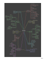
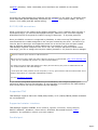
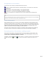
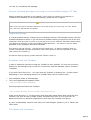
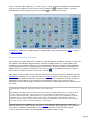
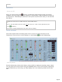
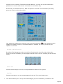
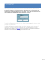
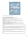
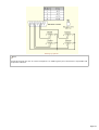
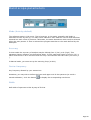
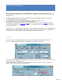
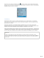
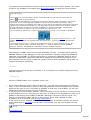
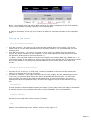
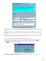
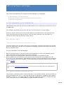
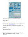
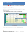
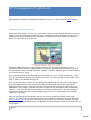
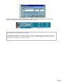
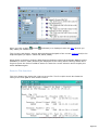
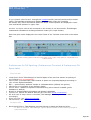
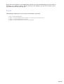
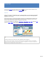
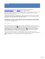
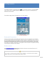
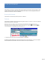
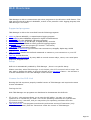
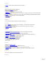
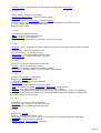
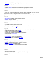
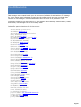
TRX-Manager: features map
This diagram shows the various functions grouped by main features.
Page 5
Page 6
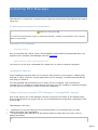
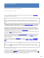
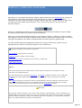
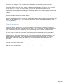
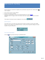
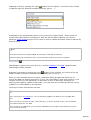
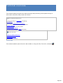
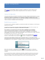
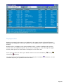
Getting help
TRX-manager features a very comprehensive help system. Most windows have a help button
and many controls have touch help.
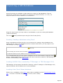
Index is the best approach to search for a specific information using known Keywords. If you
don't find you may try the Search function.
You may also print any section or all the topic using the Print button.
Page 7
Requirements
TRX-Manager requires:
Probably a transceiver or a receiver!...
A Personal Computer and any 32 bits or 64 bits version of Windows (except NT3.51)
Graphics card 16 or 32-bit color video display adapter
X-VGA monitor (minimum)
A free serial port for the radio interface or an USB/Serial adapter (Com 1-32 supported)
Eventually an RS232/TTL Level converter (but most recent rigs include this converter)
A Connection to the Internet (optional)
A TNC or multimode controller + serial port (optional) for DX Spotting
A rotator interface + serial port (optional)
A free parallel port for the band decoder (optional)
DCBS Systems
Sorry, but TRX-Manager is NOT compatible with any version of Windows using DCBS (China, Japan,
Taiwan, Korea) and Windows NT3.51.
Disk space
The necessary disk space to install the software is about 50 Mb (it may depend on the
software already installed). At least, 200 MB of free disk space are required to run the
program.
RAM
Recommended minimal requirement is 124 MB (Windows 9.X). Much more RAM is required under
XP and later.
Display
The preference menu Software tab offers you a choice of suitable colors, font type and size.
The program is optimized for a 1024*768 / 32 bits color display or more. You may have to
adjust your Windows settings (size of title bars) if some dialogs are truncated.
RS 232/TTL interface
This § is of concern only with the older transceivers (before year 2000/2005) since all
transceivers now include the RS232/TTL interface.
You need an RS232 interface to connect your transceiver to the RS232 port of your
computer. While recent transceivers include such interface (in that case, you only need a
cable between the radio and the computer), the others require an external device. The
following types are recommended : FIF232C (Yaesu), CT-62 (FT-100), IF-232C (Kenwood)
or IF-10 (TS-440/940/50), CT-17 (ICOM) or the universal LCU-3 distributed byPDA (USA)
Page 8
andWiMo (Germany). Other reasonably priced interfaces are available on the market.
Cable
Generally the cable between the computer and the interface (or the radio) is a straight wired
serial data cable (RS232 DB9/DB9). Exceptions are: FT-847 (null modem cable), FT-100 (
Yaesu CT-62 cable) and JRC (special wiring).
RS 232/USB converters
While a com port on the mother card is always preferable, if your computer does not have a
serial RS232 input, you need an RS232/USB converter. Make sure your converter supports
RTS/DTR/CTS/CTS as required for CW/PTT keying/TX Interrupt... or by some protocols.
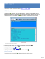
Once your RS232 converter is recognized by Windows, in order to set up TRX-Manager, you
must determine the number assigned to the com port created by the driver. You have to go
into the Device Manager and expand the Ports line to see the list (the com port number
may be different depending on which USB device is connected to your computer).
TRX-Manager supports com ports from #1 to #32. If a com port has been created outside
that range, you can re-assign the com port number (between 1-32) from the device manager.
How to choose your Serial to USB Converter
USB to Serial converters built with FTDI chips are strongly recommended (http://www.ftdichip.com/
); they are very reliable and provide very fast communications.
The cheap converters built with PROLIFIC chips (and all clones) are prone to malfunctions and
slow communications with TRX-Manager.
A multi-ports PCI card (internal to the computer) is a very good solution which minimizes RFI and a
cheaper alternative to 4 separate USB/Interface Cable.
See also Serial Port and USB
If you use the integrated USB interface of your transceiver, don't forget to power your
transceiver before running TRX-Manager. If your interface is not powered, the USB interface
does not work and can not be recognized by TRX-Manager.
Supported TNC
TRX-Manager supports TNCs with TAPR (KAM, PK232) or TF (TNC2S,TNC3S) PROM. Hostmode
are not supported.
Supported rotator interface
TRX-Manager supports SARTEK, Orion (PA PX), HyGain, Prosistel, Yaesu/Kenpro,
EA4TX's ARSWin , WinRotor, Green Heron, AlfaSPID, MicroHAM and KCT rotator
interfaces. It is possible to control up to two rotators.
Parallel port
Page 9
The TRX-Manager's band decoder emulates a Yaesu radio on pins 2-5 of a parallel port (other
band data formats are possible). Parallel port can also be used for CW keying and is
programmable for the control of an external device (such as amplifier...) or for SO4R
information.
Windows 8/64bits
Under recent versions of Windows 64 bits, the LPT driver (third party)may not work. Please note,
until now, that no fix is available and that a such fix is unlikely. Supporting LPT ports is more and
more difficult under Windows.
Other devices
TRX-Manager supports SteppIR beams (Synchro), Alpha amplifiers (TRX-Synchro), ACOM
amplifiers and Winkey CW Interface.
Digital Vector Wattmeter LP-100 and LP-100A ALPHAPOWER 4500 series Elecraft W2
are supported.
Page 10
Installing TRX-Manager
TRX-Manager is installed by a program which copies the required files and registers the system
resources.
Preparing your system for installation
Under XP, Vista, W7, W8
You must have administrator rigths to install TRX-Manager. Installing TRX-Manager with restricted
rights is not possible.
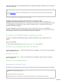
Installing TRX-Manager
Licensed version
Run your personal file: SETUP_TRX5_DYYYYMMDD_IDXXXX.EXE as downloaded after your
payment. Once installed, TRX-Manager must be registered.
Demo version (from a downloaded file)
You need to run the auto extractable file (trmde5.exe) in order to install the program.
Installation options
If the installation software asks you to keep the files present on your system : Please press
first YES or (OUI). However, if the program does not run properly, uninstall and press NO the
next time you install it.
It is also possible that Setup asks you to power off your computer: this is normal and
necessary for the update of certain shared resources; once the computer is powered on again
you may have to run Setup in order to finish the installation.
Folders structure used by TRX-Manager ("Use AppData" option)
Prior to CD Version 4.5.5 TRX-Manager used the Program Files folder as the default folder;
this old scheme does not comply with the current specifications of Windows, especially if UAC
is set to ON.
TRX-Manager V5.X uses:
..\AppData\Local\TRX-Manager as the default folder for all personal files (you may
backup this folder for reinstallation)
..\ProgramData\TRX-Manager as the default folder for utility files (you don't need to
backup this folder)
Tip
Page 11
You may browse AppData\Local\TRX-Manager from the Parameters\Browse submenu.
TRX-Tools.exe (distributed with TRX-Manager) lets you browse all the folders that TRX-Manager
uses including the Backup folder.
Note
If you own an older installation (CD prior to 5.0), TRX-Manager switches using the new folder
structure. Please note:
TRX-Manager will automatically copy temporary and utility files located in the TRX-manager's main
folder to the new \Misc subfolders (located in ProgramData\TRX-manager and in
AppData\Local\TRX-Manager),
BUT TRX-Manager does NOT move your personal files (i.e files created using the Open/Save
buttons, your LOG or SWL database, your MEM files and generally all files located in the
TRX-Manager's subfolders...). Consequently, almost all files located in the TRX-Manager's
subfolders will NOT be moved and will stay in the Program files\TRX-manager's folder and
TRX-manager continues to write Program Files!. It is up to you (but strongly recommended) to
transfer these files to the new location (AppData\Local\TRX-manager's subfolders) and to configure
TRX-Manager accordingly.
Running TRX-Manager under VISTA/Win7/Win8
TRX-Manager is compatible with Vista/Win7/Win8: so please DO NOT use WIN98 or WINXP
compatibility modes since TRX-Manager will certainly not work properly. In the Compatibility
tab for TRX-Manager.exe, you have to keep this option NOT checked. If something does not
run properly, please be sure that "Compatiblity" is NOT checked as it introduces serious and
unpredictable issues...
See also: Getting started
Installing an update
To install and update TRX-Manager, you must have administrator privileges.
Installing the updates is automated : after you download the trmup5xx.exe file from the
TRX-Manager's Whatsnew page, you run the patch file. Its setup will find the installation
folders, checks for your registration and updates the necessary files.
Installing an upgrade (new version) or installing TRX-manager on a
new computer
If you need to uninstall and reinstall the program, or to install a new copy of the program, the
following procedures are recommended:
Do not delete any file or folder manually!
Backup you most important files such as Logbook (*.mdb), memory files (.mem), short
wave database files (.mdb). It is recommended you backup all the TRX-Manager's
subfolders located in AppData\Local\TRX-Manager,
Save your parameters ,
If necessary, uninstall the program from the Add/Remove applet of the configuration
panel,
Install the new version using the same folder as the previous version (so that your folders
structure will be preserved),
Page 12
If the folders and registry structure (32/64bits), screen resolution are the SAME on both
computers you may use the TRX-Manager.reg file to restore your parameters on a new
computer.
You may copy all all the AppData\Local\TRX-manager folder to the new computer
(using the same location).
You still have to register
Copying system or executable files
For a reinstallation, the installation procedure must be followed completely. Copying any
EXE/DLL/OCX files or copying the hard disk (Drive Copy) or the system files from one computer to
the other can make the application unstable and may prevent any further installation.
Never copy the content of the main Program Files\TRX-Manager's folder (with EXE/DLL/OCX files) on
another computer since this can make the installation unstable,
Page 13
Getting started
Please run TRX-Manager from the Start menu.
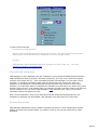
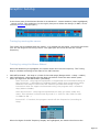
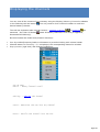
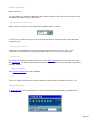
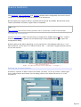
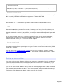
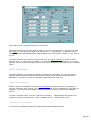
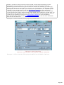
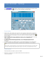
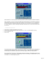
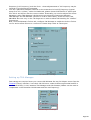
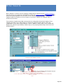
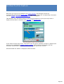
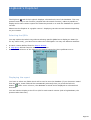
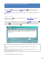
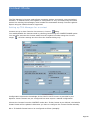
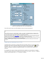
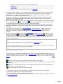
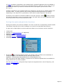
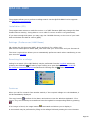
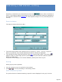
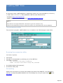
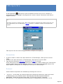
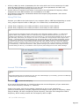
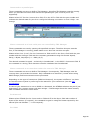
Your first session (Setup)
For your first session the software prompts you to choose the Language, the IARU Region
and pops up the Setup dialog box.
TIP
For this first session, please KEEP THE DEFAULT settings unless you understand exactly your
changes. The only exception is DTR which may be required to power on your RS232/TTL interface (if
used).
Usually, you only need to choose your transceiver under TRX1, the desired serial port and
(if available) the Speed. In some cases (if you note a communication problem ) you will have
to check DTR or RTS Enabled (especially if your interface is powered on by the computer).
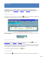
Handshaking will be automatically set by the program if you select some Kenwood (speed
above 4800) or TenTec. Otherwise, this option is not required and may lock up the program at
startup if your transceiver does not support handshaking (in fact this option only exists for a
compatibility with some serial servers). See also Troubleshooting .
If you use an ICOM, please fill in its address, fill in the number of memories and check C00
if the channels are numbered starting from #00
Initially, you DO NOT need to fill in the PTT or TRX-Interrupt frames (please let TX Interrupt
NOT checked) to make the software operating. In the same way, the IP Port option which
provides a remote control of the com port but requires a good knowledge of the program
remains unchecked.
Later on, you can add an other Transceiver under TRX2 to TRX4, choose your Preferences :
language, colors, filters and other miscellaneous settings (Terminal, Rotator, CW, Synchro ,
SO4R)…
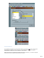
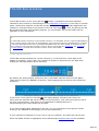
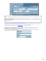
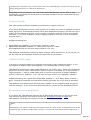
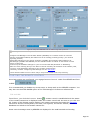
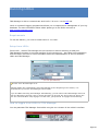
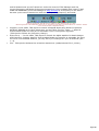
IMPORTANT
Make sure of your settings (especially Transceiver, Speed and Serial Port) are correct. Click the
summary button
to see the list of the selected com ports and check for the duplicate selections.
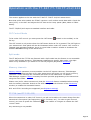
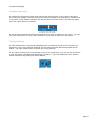
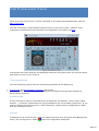
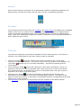
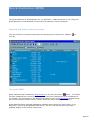
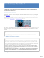
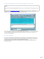
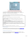
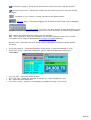
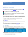
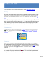
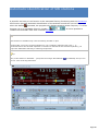
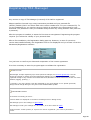
Running the Monitoring
To check if the software correctly communicates with your transceiver, close the Setup
window and activate the Monitoring module using the Transceiver/Monitoring submenu or
the corresponding button
(F6). With some Transceivers, you must press the CAT button
(main toolbar or Transceiver submenu) to engage computer control.
Page 14
If necessary, you can also access more controls from the Levelswindow (
Transceiver/Levels submenu).
Internet
TRX-Manager uses Internet Explorer's settings. Please configure you firewall to allow
TRX-Manager accessing to the Internet or your personal network.
User manual
Now, please read some of the help topics... for this purpose, a printable help is available for
download from the TRX-Manager's website . Reading the sections related to the graphical
interface and windows layout is particularly recommended.
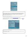
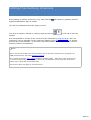
Some VERY frequently asked questions
1) TRX-manager offers a great number of programmable automatisms: some of them can be
disconcerting... One of the most frequently asked questions is related to the mode and filter
settings (including DSP or EDSP, Slope Tuning, Filters).
Frequently asked question:
The program is buggy ! It sends commands (mode or filter, DSP, Slope changes...) to
the transceiver...
Answer :
TRX-Manager provides an auto-mode function: the mode change is done according
to a programmable band plan. Please see the section related to the modes and filters
(including DSP, PBT...) and to the band plan for understanding the logic of the program
and set auto-mode OFF (Monitoring) or from the Preferences/Transceiver/Band
Plan tab if you don't like this function.
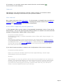
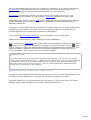
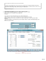
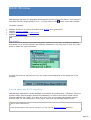
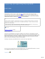
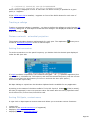
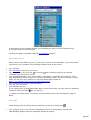
2) An other frequent question is related to the configuration of the screen at startup...
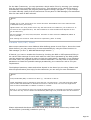
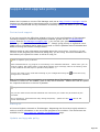
Frequently asked question:
How to do so that the windows which have been opened during a session open
automatically at the next session?
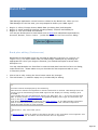
Answer:
TRX-manager can save the position and the size of each window from one session to
another. To activate this feature you must check the Previous session option under
the Software tab of the Preferences . This option should be checked only after
you make sure the program correctly communicates with all your devices in
order to avoid a repetitive look-up at startup...
Page 15
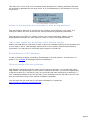
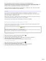
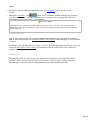
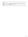
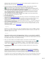
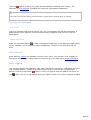
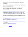
Activ ating the Prev ious session option
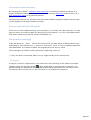
3) About Time and Date
Frequently asked question:
When in edit mode (Normal QSO mode) the Log time is 24 hour Zulu format but when
switching to List mode the time is displayed in 12 hour am/pm mode?
Answer:
TRX-Manager follows Windows Regional Settings for Time, date, etc... See also
Graphical interface and preferences.
Use with old computers
TRX-Manager is still compatible with old computers running Windows 95SP1/98 and Pentium
II/III 500M/1GHz class processors. On these computers, you may notice that the program
seems to slow down the PC... This is possible because TRX-Manager is a real-time control
program: it constantly exchanges data with the transceiver and, during this time, the
processor is monopolized! The communication loop may also slow down the use of other
software. It is therefore better to minimize the software as a task bar's icon while using other
software since the CAT loop pauses while you minimize the main window. Please read also the
section related to the use of the TRX-Manager's OLE interface with LOGic to get more
information about this particular case.
With recent computers running true multi-tasks OS like Windows XP/Vista/Win7/8, this
drawback is generally not perceptible: TRX-Manager uses less than 2% of CPU time.
System Resources
TRX-Manager implements a large number of graphic functions in each independent module.
Please only open the modules which you need in order to free up the resources for other
programs.
Page 16
Graphical interface and preferences
The program allows choosing various preferences from the Preference submenu. Each Tab of
the Preferences dialog boxes is related to a particular module. Please click the help
button
for getting help about the displayed tab. Below, only general settings are described.
Interface overview
The software uses the Multi Documents Interface system. Each window is displayed inside
the same container. You can minimize or resize most windows in order to adjust your
interface as you want.
The program keeps in registry window's position and size. You may also automatically recall
the last session (see below and Windows layout).
Opening the last session
You may quickly re-open the last screen's configuration from the File/Previous session
submenu. You also may automate this procedure by checking the Previous session option (
Preferences , under Software).
Customizing the main tool bar
The user may customize the main tool bar: a right click on the tool bar or the
Display/Toolbars... menu opens the editor (Customize). It is possible to remove, to move
(…) any button, and to set Large icons. Moving, adding or removing of the buttons are done
by drag and drop when the customization window is open.
Page 17
Custom buttons
It is possible to associate up to five buttons with any program of your choice. Please open
the Preference submenu, under software, to associate a button
with a program.
TRX-Manager extracts the icon so it appears on the tool bar.
Please note that the corresponding program opens from its directory. To remove a program,
first press the delete button then the button to delete.
Page 18
If the associated icon is not properly extracted (like with MS-DOS programs), please copy the
desired icon (16 X 16 pixels) into the TRX-Manager's directory and rename it as PROGi.BMP
(i= 0 to 4).
Personalized Menus (Office 2000 type)
By default, TRX-Manager shows all submenus (menu commands).
TRX-Manager'sPersonalized Menus feature enables to focus on just the commands you need
and use. To enable the Personalized menus, please open the Customize dialog box (as
indicated above) and checkMenus show recently... under Options. Once this option is
checked, the menus will contain those primary commands that are used some 95 percent of
the time; infrequently used commands, known as secondary, are not displayed, resulting in a
simplified user interface. At the bottom of each menu is a button that expands the menus to
the full selection of choices so you can still easily find all menu commands. As you access
menu commands, those commands are "promoted," while unused menu commands are not
displayed. Over time the user interface will be tailored to your needs. If you need to reset the
usage patterns back to the original settings, please open the Customize dialog box (
Display/Toolbars submenu) and under Options , clickReset my usage data.
Customizing the modules
Under the software tab ( Preferences) you may set different options to customize the
colors, the font for some labels or lists and how the buttons are displayed for the different
modules.
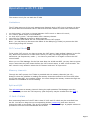
The Active colors check box determines whether the picture displayed for each toolbar's
button is changed to grayscale when the mouse pointer is not over the button.
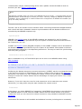
Activ e Color OFF
Activ e Color ON
The Large Icons check box determines whether the pictures displayed for buttons are
enlarged. Please note these options have no effect on the main toolbar which is fully
customizable (see above). Any toolbar can be docked in any one of the four sides of its
container, as well as be made to float. Hold the mouse and drag the toolbar where you
want...
Page 19
You may choose to display the icons related to each tab by checking the Icons check box (
Preferences under Software). Note, on some PC, the size of icons may be too large and
cause a wrong display.
The Active Resizer check box resizes most windows. It maintains the same proportions and
locations of controls relative to one another. This option optimizes the available space but
slows down the loading of the program.
The Active Borders check box gives a raised 3-D border that appears only when the mouse
pointer is over some controls:
Activ e Border OFF
Activ e Border ON
By clicking the follow upbutton
you can access more settings:
Page 20
Setting time and geographical position
You have to set up the parameters for Time via the Preferences submenu under Location .
By default, TRX-Manager uses the system time; the system time should be equal to the UTC
time. If you prefer, or if the displayed UTC time is not correct, you also may use the local time
with a convenient offset (PC-UTC).
Then you have to set Longitude and Latitude (sexagesimal format while East from
Greenwhich and North from Equator are positive values) to get correct azimuths and
distances.
Date and Time are displayed using the Windows regional settings.
Stop Sleep Mode
If Stop Sleep mode is checked, TRX-Manager prevents Windows from going into sleep mode
and running a ScreenSaver. TRX-Manager does not really disable these functions but moves
the mouse (by some pixels) to simulate an activity each 5 minutes (unless a real activity is
detected). The corresponding mouse movement is not perceptible
Language
You can choose your preference language for the interface : French, English, Swedish
Spanish German or Polish from the Preferences sub menu under Software.
Help is tranlated in English and French only. Spanish (F) displays the French help and
Spanish (E) displays the English help.
TRX-Manager itself is translated ~100% in English, ~99% in French and from 50% to 90% in
other the languages. However, many error message may appear in English only and sometime
in French. Since the software is conceived as a multi language software, with your help it is
possible to quickly translate each label into any language (please contact the author). It is
also possible to improve the various translations - thank you for your indulgence!
Distances
The distances can be displayed in Miles or Kilometers.
Regional settings (Windows)
Page 21
Dates and Times are displayed according to the format defined for Windows : please set
these preferences from the Windows's Regional Settings Panel ( Date and Time property
pages).
Using the period (.) as decimal separator is highly recommended! Please set this parameter
from the Numbers property page.
Page 22
Windows layout
TRX-manager features various functions relating to the windows.
Position and size of the windows
All the windows can be laid out on the screen as you wish. Most windows can be minimized as
icons in the lower display area but only a limited number of windows can be maximized (i.e. to
occupy all of the screen). However, most windows can be resized with the mouse to adjust
the size of the characters or the data.
Normalizing a window can be done by clicking its title bar.
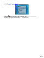
How to locate the open windows?
The Windows menu lists the titles of all open or minimized windows. Just click on the title of
the desired window. If the selected window is minimized, it will be normalized.
Page 23
Reorganization of the windows
The Windows menu offers the standard Windows's functions:
Cascade : positions all the windows in cascading fashion. The windows are resized with
their default size.
Tile horizontal : lays out the windows - one on top of the other.
Vertical mosaic : lays out the windows - one beside the others.
Arrange icons : the icons of the minimized windows are re-aligned.
Reset : the windows are re-initialized with their size by default without changing their
position.
Note
The Tile Horizontal/Vertical menus resizes the windows to occupy the maximum area of the display.
In practice, this function produces rather undesirable results.
Active resizing option
Some windows provide active resizing: Active Resizer maintains the same proportions and
locations of controls relative to one another. The Active Resizer also dynamically adjusts the
size of the fonts used in the controls, so the size of the text in a control remains proportional
relative to the overall size of the control. This option optimizes the available space. This
option is set from the Preference dialog box, under Software.
This option does not affect all the controls: for example, grids and listings are not affected.
For those controls, you may have to adjust the size of the font manually (if available).
Saving the position of the windows, recalling a session
At the end of each session, the program saves the size and position of each window. This
configuration is automatically recalled the next time you start TRX-Manager if the previous
session option in (Preference/Software) is checked.
In addition, saving and recalling a particular session (i.e. position and sizes of each window) is
possible from the File
Open /
Save Session sub menus. Sessions are saved as .trx
files.
Page 24
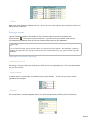
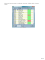
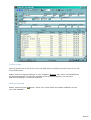
Database Grids
TRX-Manager uses configurable grids (Infragistics Data Widget 3 library) to display the
database ( SW List, LogBook, Prefix...). This section summarizes the common methods for the
use and the configuration of these grids.
Manipulating and configuring the grids
Scrolling the database
Scrolling the database is possible using the horizontal and vertical scrollbars.
horizontal and v ertical scrollbars
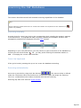
Resizing the columns
The columns may be resized using the mouse in the same way as with Windows's Explorer.
resizing the columns
Moving the columns
The columns are moveable by moving their header or from the drop down menu which appears
in the header. SW Database is displayed by groups of data: groups may also be swapped.
mov ing or swapping the columns
Splitting the grid
Grids may be divided by moving the splitter. This provides horizontal scrolling while keeping a
fixed section.
Page 25
mov ing the splitter
Colours
Odd lines uses Windows default colours ; colour of even lines may be set from the Preference
dialog under Software.
Saving a layout
Layout changes (position and width of the columns) may be saved by pressing the
layout button
. The layout is then saved as a .grd file having the same name as the
corresponding database; this file will be recalled when opening the database.
Example
You are working under TRX-Log.mdb. When you press the layout button, TRX-Manager creates or
updates the layout file TRX-Log.grd; this file will be recalled each time you open the TRX-Log.mdb
database.
Editing the records, sorting
Selecting a record
Selecting a record is done by clicking any field of the corresponding line. This record becomes
the current record.
Direct editing
In some cases, records may be edited from the grid directly : a click on any other record
validates the changes.
direct editing
Buttons
For some fields, a button appears when you click the field and provides various functions.
Page 26
column button
Sorting
To sort a column, you have to select this column by selecting any record from this column or
the header ; an action on
and
buttons provides sorting by ascending or descending
values.
Navigation bar
The navigation bar provides additional functions :
nav igation bar
: these buttons jump to the previous/next page/record in the database.
(Update) : validates the changes made from the Grid.
(Cancel) : Cancels the changes made from the Grid (before validation)..
(Delete) : Deletes the current record
(Add Bookmark) : Adds a bookmark for the current record
(Clear All Bookmarks) : Clears all stored bookmarks.
(Go to Bookmark) : Presents a list of all stored bookmarks :
(Find) : Invokes a Find dialog, allowing a search of the database. Select a field (Column
to search), the search criteria (Match), the direction (Up/Down) and the value of the field (
Find ).
(Find Previous Find Next) : Searches backwards/forwards in the database for the next
occurrence of data specified in the Find dialog.
Possible problems
1) After updating the program, the new fields do not appear: please delete the layout file
(.GRD) associated with the current database in order to reset the layout of the grid to the
default.
2) I f the grids appears empty or corrupted, you have to delete the layout file associated with
the database. The next time you open the database, the default layout will be displayed.
Page 27
Saving your parameters
Saving your parameters
The Parameters/Save Parameters subenu saves all your current settings (Setup and
Preferences) into a reg file (TRX-Manager.reg).
Depending on your system and version, the TRX-Manager.reg file may be located:
1.
2.
in the TRX-Manager\Backup folder
in the AppData\Local\TRX-Manager\Backup folder (by default since TRX-Manager V5.X)
Restoring your parameters
To restore your parameters, you have to exit TRX-Manager and double click the
TRX-Manager.reg file or use the TRX-Tools software delivered with TRX-Manager (Restore
Parameters command). Pay attention to the file paths which will be restored with your
settings..
Exporting the parameters
It is possible to restore your parameters into an other computer by running the
TRX-Manager.reg file.
Please pay attention to the file paths which must be the same ones as on the computer on
which the TRX-Manager.reg file has been created. You must then use the same organization
of your hard disk.
Warnings
Do not export the parameters into an other computer if it does not have the same screen
resolution or does not have the same folders structure.
Do not export parameters from a 32 bit system to 64 bit systems (or vice versa).
If this operation is done by mistake, you may have to invoke the TRX-Manager's
Windows/Reset submenu for each layout in order to restore the default positions of each
window or to delete the whole Registry key (HKEY_CURRENT_USER\Software\VB and VBA
Program Settings\FT-Manager).
About the registration
The registration information is not saved.
It is recommended to restore the parameters AFTER you register the software: in some case,
restoring the parameters may erase your registration.
Page 28
Saving, restoring your personal files
See also : Installation, Reinstallation and the note about the TRX-Manager's folders
structure
All temporary and utility files are located either in the TRX-manager's main folder or in the
ProgramData\TRX-Manager\Misc folder (depending on your CD version and option for Use
AppData ). Generally you don't need to save these files...
All critical and personal files such as Logbook database (.mdb), SWL (.mdb), MEM
(.mem)... files should be located in the AppData\Local\TRX-Manager subfolders. However, if
you have upgraded from an older version, your files may be still located in the TRX-Manager's
subfolders depending on your version and option for Use AppData . It is recommended that
you backup all these subfolders.
Warning
Please never copy any EXE/DLL/OCX file from one computer to the other. This is useless and can
make a reinstallation very difficult and unstable.
Page 29
Uninstallation
Easy and clean uninstallation is provided by using Windows utilities.
Automatic uninstallation
The software may be fully uninstalled using the standard Windows's utility (configuration
panel: Add/Remove applet).
During the process, the software may ask you to keep or to remove some of the shared files.
You have to select REMOVE ALL for a full uninstallation (including not shared DLL or OCX files).
Whatever your choice is, the software will not delete effective shared files if they are
correctly installed. But if you choose "KEPP ALL" the software will mark these files as "SHARED"
and it will not be possible to remove them later.
Manual operations
It may be necessary to delete the ..\AppData\TRX-Manager folders manually because the
uninstall applet doesn't recognize files created by the software. You may also save the
content of this directory if you wish to reinstall TRX-Manager later.
If you don't think to reinstall TRX-Manager, you may whish to delete the whole registry key:
HKEY_CURRENT_USER\Software\VB and VBA Program Settings\FT-Manager.
Page 30
Troubleshooting guide: Installation and use
Please read all!
This section summarises the most frequent problems (communications excepted) encountered
during the installation or the use of TRX-Manager. Please read ALL!
How to delete and change parameters without opening TRX-Manager?
If you can not open TRX-Manager because of wrong settings and errors at startup, you can
delete or change some parameters without running the program.
TRX-Manager stores all parameters and settings in the Registry. The little program called
TRX-Tools.exe and delivered in the TRX-Manager's main folder allows you doing some
operations on parameters without running TRX-Manager or opening the Registry. See also
Saving your parameters.
About the system
To run this software, the minimum required version is Windows 95 SP1. TRX-Manager has been
tested on all versions of Windows up to Windows 8 32 bits and 64 bits.
Crash during installation
In case of a crash during the setup process please make sure to exit all software (anti-viral
software included). A crash often occurs because Setup can not update the DLL loaded in
memory by other software.
Please note that 256Mb RAM is the minimal requirement on Windows 95/98, 1MB on XP and
2MB on Vista and later.
Error messages during installation
To install and update TRX-Manager under Windows Vista/Win7/Win8, you must have
administrator privilege .
Please make sure your system is up-to-date. In some cases, an error message appears
because certain of your system files are out-of-date and incompatible with those necessary
for the installation of the program. In theory this problem should not occur if your version of
Windows is higher than 95 + SP1 and very rare since XP.
In certain cases, a system file may be failing to register because the file may be locked (in
use) at the time of file transfer. Files that commonly have this problem should be registered
upon reboot of the system.
Page 31
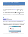
Some anti-virus using Heuristic analysis are prone to display false positive warnings. If you get
a message like "Windows cannot access the specified device, path or file. You may not have
the appropriate permissions to access the item", you have to disable your anti-virus during
the installation.
Error messages at run-time
Unexpected system error or crash
These problems can occur the first time you launch the program but in general after the
installation of another program which crushes the system files by older versions or versions
not compatible with your system. That should not occur but the experiment proves the
opposite. This incompatibility exists because some of the software installed are using different
version of some DLL or OCX (shared programs used by other software). You may also come
across the same incompatibility with any VB5/6 software.
It will then be enough to reinstall TRX-Manager. On Vista and Windows 7/8 it is recommended
you install the Cumulative Update Rollup for VB6 (Vs6sp6B); it is available on the support page
(see http://www.trx-manager.com/support.htm#43).
Frequent crashes or system lock-up at startup
Please try to reduce the number of program running in background. Try also to switch
Windows into 16 bits color mode : if that fixes the problem, please try to update your video
driver to the latest version.
INITIALIZATION ERROR. PARAMETER 6
You get this message:
The Jet VBA file (VBAJET.dll for 16-bit versions, or VBAJET32.dll for 32-bit versions) failed to
initialize when called. Try reinstalling the applications that returned the error.
or
INITIALIZATION ERROR. PARAMETER 6 ...VBAJET32...
This error happens because the MS Jet 3.51 database engine's DLLs on your computer are
mismatched. TRX-Manager uses the MS Jet 3.50 version. It works fine with the 3.51 version
but some programs feature a wrong installation package with mismatched or missing DLLs.
It is generally enough to process as follow, please :
1.
2.
3.
Search for DAO350.DLL on your computer,
Rename DAO350.DLL as DAO350.BAK,
Reinstall TRX-Manager.
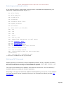
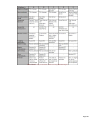
For information, TRX-Manager is installing and requires the following MS Jet's DLL :
DLL Version
DAO350.dll
3.50.3602.0
Page 32
MSJet35.dll
3.50.3602.4
MSJInt35.dll 3.50.3602.5
MSJtEr35.dll 3.50.3602.0
MSRD2x35.dll 3.50.3602.0
MSRepl35.dll 3.50.3602.0
VB5DB.dll
5.00.3724
VBAJet32.dll 5.0.7122
-2147023067 (80070725) : Automation error
This error may occur under Windows 95/98. It is caused by the installation of OLE Automation
system files not compatible with your operating system. The following table lists system files
required by TRX-Manager under Win XP and Win 9.X : version 2.40 is required under Win9.X
while version 3.50 is required under Win XP. Version 2.40 is installed by TRX-Manager under
Win 9.X only.
DLL-> For Win XP 9X
OLEAUT32.DLL 3.502.40
ASYSFILT.DLL 3.502.40
STDOLE2.TLB
3.50 2.40
OLEPRO32.DLL 5.05.0
A repair tool is available from the TRX-Manager's support page. Please reboot your system
after the installation.
Other runtime errors or crashes
Page 33
You may try reinstalling TRX-Manager.
Drivers for band decoder not found or not installed (Setup/LPT Tab)
Please reinstall the program (or the update); don't forget to reboot your computer to
complete the installation. If the problem persists, please ask for a support.
Windows 8/64bits
Under recent versions of Windows 8/64 bits, the (third party) LPT driver may not work. Please
note, until now, that NO FIX is available.
Regional settings
A common problem may be coming from your Windows settings. TRX-Manager strictly uses the
standard Windows interface: if you encounter a problem entering a frequency with a decimal
separator such as 0.125 or 0,125 or if you get an incorrect azimuth indication please check
your Regional Settings in the Control Panel under Numbers . You have to use the same
separator as the separator defined for Windows.
It is best to use the period (.) as the decimal separator . It may be however that on
certain international versions of Windows, this choice gives an incorrect operation: in this
case choose the comma (,).
At last the digit grouping symbol must be a blank (space).
Problems with the Toolbars
It may be sometime required to reset the Toolbars to their defaults. To reset the Toolbars,
please exit TRX-Manager and run TRX-Tools delivered with TRX-Manager (Reset Toolbars
command).
If you don't have TRX-Tools , you may reset the Toolbars by deleting the \Toolbar folder.
Depending on your operating system, the \Toolbar folder may be located under:
1.
2.
The installation folder of TRX-Manager
The {user}AppData\TRX-Manager folder
Some of the Toolbars disappear
Exit the program and Reset the Toolbars.
The Toolbars buttons are not visible, distorted or black
Under Vista/Windows 7, not frequently used items may appear black while using the Aero
interface; the work around is simple: please just define any color of your choice for 3D
Objects and Menus in Windows (Appearance) and reset the Toolbars (see above).
A (rare) incompatibility may also exist with your Video adapter: please try 16 or 32bits color
video mode.
The labels are truncated
Page 34
This may occur if the little font is selected under Properties for display (Windows) because
the program is optimized for the large fonts. It is recommended you set Windows to use the
large fonts.
truncated labels in little fonts
Somes of the windows are truncated or with wrong positions
This may happen under XP or Vista if the size (height) of the titlle bar is too large. It is
enough to reduce the size of the title bar from the System's graphical preferences.
This may also occur after you change (reduce) the screen resolution. Please run the
Windows/Reset submenu for each layout in order to restore the default positions.
Last screen layout lost at startup (main window empty)
Please note that after a crash and in order to prevent automatic opening of the windows and
a new crash to occur, TRX-Manager leaves the Previous option (Preferences/Software)
unchecked. You may have to check this option again for normal use.
Reinstallation of TRX-Manager
In case of serious problem, reinstalling TRX-Manager is a good solution. In that case, it is
better if you uninstall TRX-Manager before reinstalling it!
Other problems with the software
TRX-Manager has been carefully tested, but as with any software, it is certain that some
bugs remain. As TRX-Manager is not a classic commercial product, you have the opportunity
to ask the author for a correction. Also, do not forget that each transceiver is different: a
CAT command available for the FT-920 may not be available with the TS-590 or the FT-817!
See your manual to check if the desired command is available…
You may also see the web site for the latest information or update at:
http://www.trx-manager.com/support.htm
Page 35
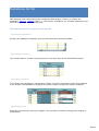
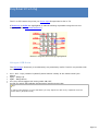
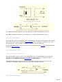
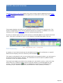
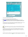
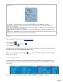
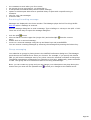
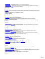
Transceivers: Overview and Settings
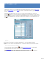
TRX-Manager can configure up to four transceivers (Setup: TRX1 to TRX4 tabs).
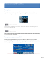
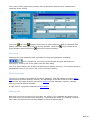
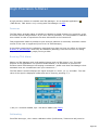
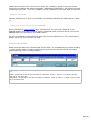
Definitions
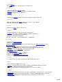
Up to four local transceivers (+ one remote transceiver) can be used at the same time:
One Transceiver is called Main and is controlled from the Monitoring window. The Main
Transceiver can be selected from the Transceiver menu.
The other three Transceivers are called Sub-Transceivers and are controlled from the
Sub-Transceivers panels. Not all Transceivers are supported as Sub-Transceiver.
The Operating Transceiver is the one activated for the various modules of TRX-Manager.
By default, at start-up, the Main Transceiver is the Operating Transceiver but a
Sub-Transceiver can be defined as the Operating Transceiver at any time during a session
(see below about the Operating transceiver). The Remote transceiver can be configured
as the Operating transceiver as well.
The Main Transceiver has a comprehensive support while a Sub-Transceiver or a Remote
transceiver only supports essential functions and programmable macros. Synchronization, Drag
and Drop is possible between transceivers. OP function, support of SO4R mode (Single
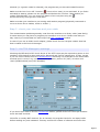
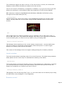
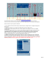
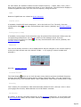
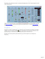
Operator Four radios) provides great flexibility in the use of five transceivers at the same time.
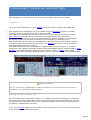
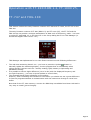
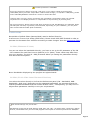
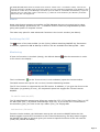
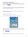
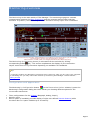
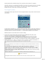
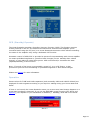
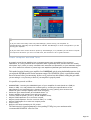
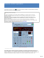
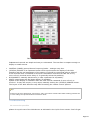
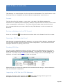
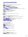
Sub=TS-590S (left), Main=K3 (right)
Operating transceiv er =TS-590
When transmitting
There is no function in TRX-Manager to protect a transceiver in receive mode while an other is
transmitting. You must switch it OFF manually!
Setting up your transceiver
For each Transceiver, from Setup/TRX1..4 , you define the type of Transceiver, the Serial
Port and select the communication Speed. For some transceivers DTR or RTS case must be
checked but more often this option is only required to power on the RS232 interface and not
to support a communication protocol.
If you use an ICOM, please fill in its address, fill in the number of memories and check C00
if the channels are numbered from #00.
Page 36
For a TS-2000/480/590/K2/K3/KX3 (or Remote) transceiver, if you choose the internal
CW Interface, check CW Internal (CW via CAT port). For these transceivers any other
settings made under the CW tab will be ignored while Internal is checked.
PTT options are required in case of you don't use PTT (TX On/Off) via CAT or if your
transceiver does not support PTT via computer. TX Interrup settings are rarely used.
Under TRX1 tab, you also find the SO4R option (Single Operator Four Radios) which provides
various switching options via the parallel port or automatic selections depending on the
Operating transceiver.
Ck Buffer is usually NOT checked. If checked, the program checks for an empty buffer before
sending any new command. This may reduce the number of collisions and errors but the
program may also lock up with some comm drivers (like Prolific).
If you own an LP-100 Digital wattmeter, you can configure it from Setup/TRX1
Please restart TRX-Manager after checking for all the parameters.
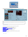
Now, you launch the Monitoring which is the heart of TRX-Manager by clicking the Monitoring
button or F6. With some transceivers, you may have to click the CAT control
button
(if it is visible) to engage the communication between the program and the transceiver. If all
has been properly configured, the Monitoring window displays the current state of the
main transceiver and you can control it from the computer.
About com ports
If you select the same com port for different transceivers or devices, you will receive a warning
message (like "Erroneous parameters..."). While this is is a Warning only and this configuration will
be accepted by the program it is recommended you take care not using these different devices
sharing the same com port at the same time... since it is NOT supported by Windows and may
generate an error at startup of TRX-Manager.
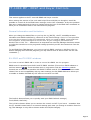
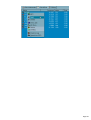
Selecting the Main Transceiver (Monitoring)
The Monitoring window controls the Main transceiver. When you start TRX-Manager for the
first time, the main transceiver is generally the one defined under Setup/TRX1.
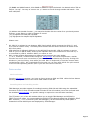
The Main Transceiver can be selected at any time from the Transceiver menu. This menu
displays various items corresponding to each configured transceivers:
Page 37
About com port (main transceiver)
The serial port for the main transceiver is opened as soon as the program starts and closes when
you exit TRX-Manager; however, it can be temporarily closed using the Transceiver/Com Port.
submenu. Whatever its state when you exit TRX-Manager, the com port is always activated at
startup. You can check the status of the com port and the transceiver selected from the
Parameters/My Configuration sub menu.
Control of a Sub-Transceiver
To control a Sub-Transceiver you open the Sub-Transceiver panel from the
Transceiver/Sub...submenu. Only Transceivers supported as Sub-Transceiver (see list) are
displayed in this menu.
About com port (sub transceivers)
The sub transceiver's com port opens only as you open the Sub-Transceiver window and closes
when you closes this window.
Preferences
Page 38
The Transceiver's preferences are distinct for each Transceiver (Band Plan excepted).
Transceiver model and Logging TX Power are also memorized for each Transceiver.
Preferences are accessible only during the time the corresponding transceiver is selected as
Main Transceiver. If you need a change in the Preferences for a Sub-Transceiver, please
define it temporarily as Main from the Transceiver menu.
Definition: the Operating Transceiver
The Operating transceiver is the one activated for the DX Spots (Web& DX Cluster), the Short
Wave database, the Logbook, the DXCC module, the Quick Memories, CW Interface and the
DX Bar.
By default, at startup, the Main Transceiver is the Operating Transceiver. The Operating
transceiver can be selected at any time and very quickly using the OP button available from
the Monitoring or Sub-Transceiveror Remote control windows (i.e. this OP function provides
logging from a Sub-Transceiver...). The Preferences for the Rotator (by band) follows the
Operating transceiver.
Some modules also provide independent selection of the Operating Transceiver.
In addition, depending on the state of the SO4R option (under Setup/TRX1 tab), OP function
also links the Band Decoder, OLE , Synchronization with the Operating Transceiver.
Selecting the operating transceiver at startup using a command line switch
A switch (/TRX1to /TRX4) can be added to the command line to start TRX-Manager with a specific
main transceiver. The command line must look like this : "C:\Program Files\TRX- Manager.exe"
/TRX2 to start TRX-Manager with TRX2 as main and operating transceiver.
Frequency range
TRX-Manager covers the frequency range from 0.1 to 2000 MHz with the following accuracy:
below 160MHz
: 10Hz/1Hz
from 160MHz to 1600MHz : 100Hz/10hz
above 1600MHz
: 1KHz/100Hz
Accuracy may be higher with some transceivers.
Page 39
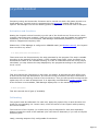
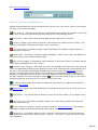
Troubleshooting guide : Serial port
The program doesn't communicate with your rig (or your TNC, Rotor...)
Of course, anything is possible, but please think first that a programming fault is the less likely.
Please read all: almost 99% of the possible situations are covered in this guide and the
TRX-Manager's support page!
Sometime, the synchronization between the transceiver and the display is lost. It is generally
enough to update the synchronization using the Monitoring's Update button. This button has
different layout depending on the transceiver you use : generic
Elecraft
, Kenwood
, ICOM
or
.
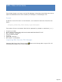
Otherwise, review all your configuration by opening the
My Configuration sub menu. All your
current configuration is displayed and allows you to review all your parameters and settings. You
can save this information into the clipboard by using the copy and paste
button.
If the program locks up at startup, you can use TRX-Tools.exe (available from the TRX-Manager's
Start menu) to reset all your settings (TRX1 to TRX4) to DEMO.
Related Topics
Troubleshooting (general)
Support page
Step 1 : cockpit check list
Please check that your Transceiver and its RS232/TTL Interface are powered up! Some
RS232/TTL interface are powered up through the DTR line of the com port (DTR must be
activated).
If you use a transceiver with an USB port, make sure the transceiver is powered up. Although
TRX-Manager may start with the Transceiver in OFF, if your transceiver is not powered up,
the USB interface does not work and TRX-Manager is unable to find the corresponding com
port. You will have an error like this one:
This TS-590 is not powered up
The USB interface does not work
Make sure the right and exact model of Transceiver is selected under Setup and select the
same Transceiver from the Transceiver menu (see Dual Setup). If the exact model is not
Page 40
selected (or a generic model is selected), the program may run but with limited functions.
Make sure the Com Port OFF function (
Transceiver menu) is not activated. It you find it
activated at startup, please exit the program and delete the \Toolbar folder before you
restart TRX-Manager. You can check the status of the com port using the
Parameters/My Configuration sub menu.
Make sure that your interface is not running with another program (physically connected or
not to a device like a modem, a FAX or a PDA...).
Step 2 : check your interface and your cable
The communication problems generally come from the interface or a faulty cable (most likely).
In some cases you may have to program your interface or to wire it. Please note that you
may control your serial data line with help of the CAT Commands window.
In case of you use an USB/Serial adapter, please check for the com port number that has
been created in the Device Manager.
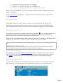
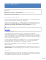
Step 3 : the TRX-Manager's settings
Checking the DTR and/or RTS check boxes of the PTT frame may be required to power-on the
interface. RTS checked is also required for Kenwood and TenTec transceivers. In fact, except
if you use one of theses lines for Transmit/Receive switching it is preferable to let these cases
checked and in case of any communication problem, please let [CAT] checked and
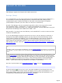
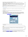
check [DTR Enabled] and [RTS Enabled].
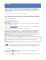
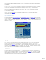
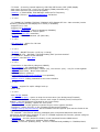
Default settings for a K3. RTS and DTR have no effect.
If you don't know how to use the TX Interrupt feature, please let the TX Interrupt Enabled
check box NOT checked.
Ck Buffer is usually NOT checked. If it is checked, the program checks for an empty buffer
before sending any new command. This may reduce the number of collisions and errors but
Page 41
this can not solve a communication problem. Moreover, this function is not supported by some
comm drivers (like Prolific) and this may lock up the program.
Handshaking is only required with Kenwoods, some TenTecs and some serial servers. It is NOT
required with other brands and may lock up the program at startup. Should this happen, you
have to use the TRX-Tools program (distributed with TRX-Manager) to reset all your
configuration to DEMO (TRX1-4= DEMO).
If the monitoring display doesn't reflect the transceiver status, check the dual control option
(Setup). Except for special cases, this option should be enabled (checked).
Step 4 : the Transceiver's settings
Check that the Setup's speed is the same as that definite for your transceiver; if necessary,
try to decrease or increase this speed.
Particular case : ICOM and TenTec
If you are using an ICOM or a TenTec OMNI VI, please check :
TRANSCEIVE function is ON (CdE on TenTec). Setting methods differ according to radios.
Refer to the instruction manual of each radio
The transceiver address of the radio is the same as the one in the Setup of
TRX-Manager
AUTO Baud (or Auto-Speed) is not selected, but select a true speed : 9600 or 19200
CI-V 731 Mode is set as OFF (except for IC-735)
In most cases, Stop Bits = 2 gives more reliable communications ; however, in some other
cases this parameter does not work properly and you must try Stop Bits = 1.
The ICOM and TenTec transceivers function better at 19200 bds.
Sometimes if you use an ICOM (or a TenTec OMNI VII), you may receive this message "
Communication error (Invalid message format)". This is a warning only which appears once
for each session. Generally, this message is without consequence ; however you can try to
improve your parameter settings.
Particular case : FT-847
Unlike most other transceivers, the FT-847 serial data cable is a null modem (crossed) type,
not a straight serial data cable.
The FT-847's microprocessor uses the same com port to exchange data with the FC-20, CAT
programs and a clone transceiver... thus this transceiver doesn't allow you to simultaneously
use the FC-20 antenna tuner and the CAT system! It is not the fault of the programmer...
Particular cases : KENWOOD ELECRAFT
The Kenwood or Elecraft transceivers function better at high speed. Please select the highest
speed available.
HandShaking parameter is selectable: With Kenwoods only, try None (NOT checked) or RTS
(Checked) if you don't have any communication. Make sure your cable supports RTS
Handshaking if RTS is selected. If RTS is selected for Handshaking, you can NOT use it for PTT
Switching or CW Keying!
With Elecraft Handshaking is NOT required and may lock up the program (this option is only
Page 42
required with some serial servers).
Step 5 : check your com ports
Choosing an USB/RS232 Interface
The RS232/USB Converters built with FTDI chips are the more reliable and are strongly
recommended! A multi-ports PCI card (internal to the computer) is a very good solution which
minimizes RFI and a cheaper alternative to 4 separate USB/Interface Cable.
See how to select your converter: http://www.usb-serial-adapter.org/
TRX-Manager can NOT communicate through a serial port that is already opened from an
other application or an other module of TRX-Manager.
From the Windows device manager, please check there is no conflict between com ports or
USB adapters. A conflict with IRQ5 (usually used by the sound card) is not detected by
Windows! If you use an ISA PC board, check the DIP switch related to addresses and IRQ are
correctly configured.
Serial to USB converters
USB to Serial converters built with FTDI chips are strongly recommended ; they are very
reliable and provide very fast communications. The cheap converters built with PROLIFIC and
all Clones chips are prone to malfunctions and slow communications with TRX-Manager.
Serial port on mother board
You may check that the BIOS Setup program of your PC reflects the correct parameters for
the serial ports (the same ones as those displayed by Windows in the device manager). Note
that in some cases, when something wrong happens at a com port (shortcut, defective cable
or interface...), your Bios disabled this com port without warning.
In practice the following parameters are most common for COM 1 and COM 2 (port on mother
board) :
COM 1 IRQ 4 address 03F8-03FF
COM 2 IRQ 3 address 02F8-02FF
Particular case : Windows ME
The software functions properly under Windows ME. However, this operating system leaves
the DTR and RTS lines of the com ports in a high state at each startup. This is important to
know for it can cause an unpleasant effect on the CW and PTT lines at the startup of the PC!
Running TRX-Manager and opening the concerned modules will set the DTR and RTS lines to
the state required by TRX. In certain cases this problem could lock up the RS-232 interface(s)
when starting your PC. A little program (ComFix.exe) available on the support page allows
you to set Windows ME to counter this defect.
TRX-Manager suddenly stops communicating
If a communication error happens, it may be enough to clik the updatebutton of the
Monitoring to resume the communications.
Page 43
Test your device (Transceiver, TNC...) with another program. Check the com port has not
been disabled by the Bios program (see above).
RFI Problems
In some cases, especially on 160m, 80m, 40m at high output power, you may have a
communication error when transmitting. This is caused by Radio Frequency Interferences (
RFI) between your rig and your PC. You should find a hardware solution (see any Handbook)
but please note this is a minor inconvenient: TRX-Manager has been written to automatically
resumes any communication error (except the first one!).
Reinstalling a com port
This is a solution of the last chance but that can be effective sometime. The steps are:
Port on mother board (for expert only)
Remove the defective serial port from the device manager
Reinstall the serial port
Check you BIOS parameters
USB/Serial Interface (or PCI cards)
You can check your equipment with an other software. However, if it passes this test, your
USB driver may still be faulty! (*).
If you use an USB/Serial interface, the following steps are mandatory:
Unplug the USB interface (or the PCI card)
Remove the com port from the device manager
If possible delete the driver manually
Reinstall the driver (to download from the manufacturer's web site)
Restart Windows
Plug in the USB interface (or the PCI card)
(*) Results depend on the way each programmer uses the com port's APIs.
Page 44
ICOM Transceivers
This section applies to ICOM radios and TenTec radios using the ICOM protocol (Omni VI
and Omni VI).
If your transceiver doesn't appear in the SETUP list, please choose the ICOM option which
should function with all ICOMs using a generic (but limited) set of commands.
Settings
Controlling an ICOM via the CI-V protocol requires a CT-17 interface or compatible such as
the W1GEE's LCU-3. Some older transceivers (CI-IV standard) require the conversion
interface UX-14 between the transceiver and the CT-17 interface.
Using the LCU-3 interface requires checking DTR to power on the interface.
Using the RS-746 interface requires checking RTS to power on the interface.
From the SETUP dialog box of the program, you must specify:
The transceiver's address such as defined by ICOM (or that which you have yourself
defined),
The PC's address (E0 by default),
The number of channels (maximum 99),
The channel numbering (please check C00 if the first channel is #00)
The baud rate.
Stop Bits = 2 (default). Rarely, Stop Bits = 1 is required (recommanded by ICOM).
Dual Control usually checked - unchecked only if you connect your ICOM to your
computer through a serial server (*)
From your ICOM radio you have to check:
The baud rate: some transceivers feature an AUTO BAUD or AUTO SPEED function.
However, it is recommended to NOT use this feature and to set the speed from the
transceiver to the highest available value. However some models may not run properly at
the maximum available speed (19200) : in that case, please select 9600 bauds.
The number of bytes for the frequency: except for the IC-735, exchange of frequencies
is done in 5 bytes : check that your ICOM is not setup for a frequency in 4 bytes.
The transceive function (or CdE on TenTec): when the transceive function is ON, any
changes in the operating frequency or mode on the radio is automatically transferred to
the computer. Make sure to set the Transceive function as ON. Setting methods differ
according to radios. Refer to the instruction manual of each radio. Warning : After the use
of some other software, this function may be set as OFF !...
Lastly, the use of TRX-Manager with several ICOM inter-connected in a network is not
advised; indeed the collisions between commands slows down the program and some
commands can not be executed.
Sometimes, you may receive this message "Communication error (Invalid message format)".
This is a warning only which appears one time for each session. Generally, this message is
without consequences; however you can try to improve your parameter settings.
(*) See also Disabling Dual Control. If Dual Control is checked TRX-Managers waits for NG and
OK messages before displaying the new status of the transceiver. Dual Control is more
secure but not compatible with the use of a serial server via the Internet.
(**) for the older ICOMS (IC-751, IC-761...) or if you select the ICOM option, TRX-Manager
Page 45
polls the tansceiver every 500ms since these rigs do not have a Transceive function.
Operation
The set of commands (from the PC) is variable from one model to the other. Due to the large
number of commands available and their diversity, only the most important commands for
real-time control are supported by TRX-Manager. These commands are available from the
Monitoring and Levels windows. Additional commands can be programmed using macros. Please
see your manual for the available commands.
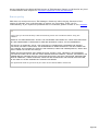
You have to set up the Filters (FIL1-N, WID/NAR...) by defaut for each Mode from the
Preference/transceiver dialog box (See also Modes and Filters). From the
Preferences/Transceiver dialog, you may also enable the AUTO PBT function (see below).
If your transceiver supports the PBT and DSP Width functions, TRX-Manager provides two
very convenient functions :
Auto PBT (IF-Shift)
From the Preferences/Transceiver dialog, you may set up the default values of PBT Inside
and PBT Outside for each mode. These values (ranging from 0 to 255) apply for both the
Outside and Inside PBT commands and allow defining an IF-Shift (i.e SFT= -150hz for a value
of 110 but to be tested...). 128 is the factory default values (click D to reset factory
defaults).
Default values of PBT Inside and
PBT Ouside for each mode
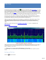
Graphical display
The Monitorings' window displays the PBT Inside and Outside bandwidths (values
approximated).
PBT Graph. Display
Note about the speed of communication
ICOM transceivers automatically communicate frequency and mode changes but other parameters
(channel number, Split mode, VFO…) that are made on the transceiver are not transmitted to the
computer. The consequences are the following:
After TRX-Manager is started, some parameters are fixed by default or unavailable. The display
progressively becomes available as commands are sent from the PC. If necessary, rotate the
dial tuning to display the frequency,
It is thus recommended to change the VFOs or to switch the SPLIT mode from the PC.
TRX-Manager does some polling of important data but gives a priority to the most critical data
(Mode, S-Meter, TX State...). Consequently the other parameters (like PBT, DSP) may refresh
slowly...
Page 46
Tips by Rich K0FUN
When TRX-Manager starts is assumes VFO A is active. If the radio is set to VFO B the program will
read this value into VFO A of the program. This can be confusing. The following prevents the
problem:
1. With the transceiver on. Start TRX-Manager.
2. Select VFO A from the program (This will insure the Radio is using VFO A)
3. Turn the VFO knob on the radio slightly. This may result in a Dialog Box indicating a
Communications Error (Invalid message format). This only comes up once and is not serious
4. Select VFO B from the program.
5. Turn the VFO Knob on the radio slightly. 6. If Split is enable on the radio disable it from the radio.
If you want to operate split enable it from the program.
Features and limitations
The number of memory channels is limited to 99 for all the models (see below).
Generally, the oldest ICOMs (before IC-746) do not allow reading of the s-meter (and
consequently the bandscope is not supported), SPLIT command (status write and/or read),
VFO A/B, PTT controls may be not available. However, if PTT control is not available, you can
still control TX/RX status using the RTS/DTR Lines.
With IC-R75, please use AM Reverse to set AM Synchronous.
With IC-PCR1000, press the
button of the main toolbar to power on the receiver.
With IC-820/821/910/9100 MAIN & SUB VFO are simultaneously displayed and updated only
if you are in SAT mode; it is important you engage SAT mode from the program (see also
Satellite interface).
Power ON/OFF
TRX-Manager assumes that the transceiver is turned on at startup. If this function is
supported, use the power button
to turn on/off the transceiver. After sending a "POWER
ON" command, you may have to press the Monitoring's Refresh
button to refresh the
display.
Warning
Depending on the transceiver you are using and the way the interface is powered on when you
switch off the transceiver, you may be unable to power the transceiver on again... Generally, if you
use a separate CIV converter (CT17 or clone) powered by a 12v source, it should work. See the
documentation provided by ICOM.
Depending on the transceiver you are using and the way the interface is powered on when
you switch off the transceiver, you may be unable to power the transceiver on again...
Generally, if you use a separate CIV converter powered by a 12v source, it should work.
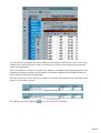
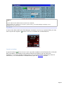
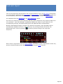
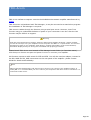
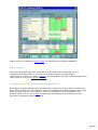
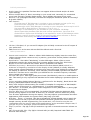
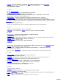
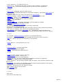
Additional functions : Levels window
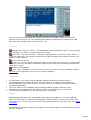
If you are using a recent ICOM (since IC-746) a lot of commands are available such as AF
Page 47
Level, Squelch, APF, NR, PBT , IF Shift, Keyer... Most of these commands are implemented
from the Level windows (Transceiver/Levels submenu or
Toolbar's button). Controls
automatically update at startup; then click ICOM
to update the controls.
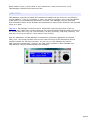
Lev els window (IC-7100)
If necessary additional commands may be implemented using the Monitoring's macro buttons
or TRX-Command.
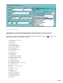
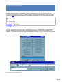
About the memory channels
The number of memory channels (= number of the last channel available) is limited to 99 for all
the models. TRX-Manager begins memory channels numbering from #1; some ICOMs begin
numbering from #0 and a shift of one unit is possible between the channel number displayed
by the program and the one displayed by the transceiver. If the first channel is Channel #0,
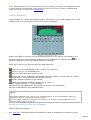
please check C00 (Setup). Selection of the memory bank (if possible like with IC-7000) is
done from the Display/Memory Channels window
.
The editing or the transfer of the channels from the PC to the transceiver is possible from the
Edit/Memorysubmenu or by a right click from the channel window. Note that if you modify the
contents of the memories from the transceiver, there can be a difference with the contents
displayed by the program. It is therefore recommended to modify the contents of the
memories only from the program. In addition the transfer of the memories to the transceiver is
very slow.
Reading the memory channels content is not supported
TRX-Manager can NOT read the contents of the memories of ICOM transceivers. It could be done,
but was not programmed in order to preserve the compatibility between the various models;
moreover data like the shift, CTCSS tones etc. could be read only from some ICOMs by a specific
command which is not available on the other models. Nevertheless, TRX-Manager reads the
frequency and the mode of each channel when they are individually accessed from the program
and preserves the values, between sessions, on hard disk.
If these functions are available on your ICOM, TRX-Manager memorizes the receive and
transmit frequencies (SPLIT mode), tonality CTCSS (repeater and T-Squelch). The repeater
shift (DUP) is ALWAYS memorized as a receive-transmit shift in SPLIT mode (except
IC-820/821/910 for which it is memorized as a repeater offset in FM).
Page 48
Recent ICOMs (IC-703 IC-746/PRO, IC-R75 and IC-756PRO/PRO2/PRO3 IC-7000
IC-7410 IC-7600 IC-7700 IC-7800 IC-9100) provides editing of the memory labels from the
PC (supported). But Destination Call Sign, Access/Area Repeater, Link/Gateway Repeater and
Digital Squelch settings are NOT supported.
TRX-Manager preserves the contents of the memories on hard disk between the sessions.
D-Star
DV mode and DV TX Callsigns (D-Star) are supported (compatible transceiver only) either
from the Edit/Frequency (F2) dialog or the Edit/Memory Dialog.
Remote control
Like all other transceivers, your ICOM may be controlled through a LAN or the Internet using
the standard remote control mode of TRX-Manager, but with limited functions. In addition, you
may also take full control over your transceiver through a network using the real remote
control mode : TRX-Manager behaves exactly like if the com port is locally controlled.
Page 49
Yaesu transceivers
Related Topics
FT-990 ROM1.2, FT-1000 V5, FT-747, FRG-100
FT-1000MP
FT-757GX
FT-767GX
FT-817/857/897
FT-847/736/212/412
FT-980
FRG-9600
FTDX3000 FTDX5000 FTDX9000 FT-2000 FT-950 FT-450
General remarks
YAESU transceivers are very different from one model to another. Consequently, many
functional differences are possible depending on the transceiver selected.
Please note the following functional differences between some Yaesu transceivers:
• The generic Yaesu selection for "transceiver" should run with various (but OLD) Yaesu
transceivers or receivers but with limited functions (setting of frequency and mode only - no
monitoring). Except for special needs or tests, do not select Yaesu but the exact model of
your transceiver.
•With FT-847 FT-736 FT-212/412, FT-767GX FT-980 to be under CAT control you must
press the CAT button
(located on the main toolbar) or the F9 key.
• Early FT-990 and FT-1000 firmware versions (prior to rev. 1.3 or V6), FT-747 or FRG-100
do not allow a constant communication with the PC. Please read the section about FT-990
ROM1.2, FT-1000V<6, FT-747 and FRG-100 for more information.
•FRG-9600, FT-757GX, or FT-736 have limited functions. Please see the corresponding
sections of the help.
• FT-757GXII allows using all the functions of the program but editing the memories,
changing the frequency or the mode is not possible when in MEMemory mode.
•With FT-817/857/897, FT-847 or FT-100 it is not possible to read/write the internal memory
channels of the transceiver : memory channels implemented by TRX-Manager are virtual and
not related to the channels of the transceiver. The FC-20 and FC-30 antenna tuners are
not compatible with the CAT system.
Page 50
• With FT-890/900 and FT-100 setting the clarifier is not supported. However, the program
reads the clarifier and displays the right RX frequency. With FT-840, the clarifier (read/write)
is not supported. This could cause the recalled frequency to be wrong.
• With FT-920 and FT-1000MP : SWL and BAND SCOPE are running only with VFO A
selected, real time scanning functions (up down ) are not supported. Some commands of the
Rig's internal electronic keyer are supported (FT-920 : Tools/Rig's Keyer - FT1000MP
Tools/EDSP). With FT-1000MP/MKV selected, scanning from the Monitoring's Up/down
button as well as from the Command panel uses the proper scanning function (smooth tuning).
This may not work properly with older FT-1000MP ; in that case, please unselect AUTO from
the Range dialog of the command panel (receiver will be muted during scanning).
• With arecent Yaesu FT450 to FTDX9000, you must define the width of each DSP filter
under Preferences/Software. See also Modes and Filters.
• With VR-5000, only 4800 bauds speed is supported correctly. Communication is not
bidirectional: reading frequency and mode is not possible. To be under CAT control you must
press the CAT button
(located on the main toolbar) or the F9 key. Under CAT control, the
display of the receiver may freeze or the S-Meter may be erratic. S-Meter only runs
properly when the sub-receiver is activated. Consequently, the TRX-Manager's BandScope
only runs with the sub-receiver in AM-N mode by defaut. Reading/writing the internal memory
channels is not possible: memory channels implemented by TRX-Manager are virtual and not
related to the channels of the receiver. VFO A = Main receiver while VFO B = Sub receiver.
The Clone mode is not supported.
Page 51
Operation with FT-990 ROM 1.2, FT-1000 V5,
FT-747 and FRG-100
This section is about the early firmware versions of FT-990 and FT-1000, the FT-747 or the
FRG-100.
The early firmware versions of FT-990 (ROM 1.2) and FT-1000 (V5), the FT-747 and the
FRG-100 do not provide a real time transmission of data such as frequency, mode… You have
to select FT-990 ROM 1.2 or FT-1000 V5 in the Setup dialog box to run TRX-Manager (or
should this happen FRG-100 FT-747).
update function
TRX-Manager was implemented to run with these transceivers with following differences :
The real time monitoring doesn't run : you have to press the Update
button to
manually update the monitoring display ; but the program does it automatically when
calling specific functions such as : memory reading, QSX, memory or QM writing and
parameters setting.
It is possible to have a slight difference (10 to 20 Hz) with the displayed frequency and
the right frequency ; you have to press Update to accord them,
The automatic band scope refreshing is not working.
However, when controlling the transceiver from the PC you should not see a great difference.
In fact the program simulates a communication with the transceiver through a virtual com
buffer.
Note that for the FT-1000 owners, a version 6.0 ROM chip is available from Yaesu USA and is
very easy to install (just a thought).
Page 52
FT-1000 MP - EDSP and Keyer Controls
This section applies to the FT-1000 MP EDSP and Keyer controls.
When writing this section of the code with help of Rocco WU2M, we thought it would be
possible to control all of the EDSP menu settings via the CAT commands. In fact the problem
was more complicated and we have to explain below the logic of the EDSP CAT commands to
allow you to understand how to use them from the program.
General information and limitations
When you change the Mode/Filter or you key the rig (RX/TX), the FT-1000MP processor
calculates new EDSP conditions by reference to the menu settings. Since It is not possible
to access the menus via the CAT commands, after you send an EDSP command from
the computer, these settings are lost as soon as you change a parameter like
Mode/Filter or RX/TX !… Please don't be surprised but note TRX-Manager has been written
to reset the transceiver to the program's settings provided you KEY the transceiver from the
program.
To use EDSP from TRX-Manager, you have to switch EDSP settings to ON from the rig
before changing them from the program (you may switch some of them to OFF via the CAT
commands…).
RX-EDSP and TX-EDSP windows
You have to switch EDSP ON in order to control the EDSP via the program.
EDSP control is possible from the RX and TX-EDSP windows (Transeiver EDSP submenu or
tool-bar buttons
). These windows work in conjunction with the Monitoring module.
Controls are as intuitive as possible. RX-EDSP TX-EDSP and AF Filters commands are mode
related. Due to an incompatibility with rig menu settings, the RX-EDSP ON button allows you
to enable or disable RX-EDSP by CAT and not to switch it to OFF.
The Default button allows you to quickly send your EDSP Default settings (
Tools/EDSP/Defaults).
The Initialize button allows you to retrieve the control via CAT if you lose it : remember that
the FT-1000MP comes back to its internal settings each time you change a condition from the
rig (TRX-Manager is only able to detect modes and TX/RX changes).
Page 53
Each time the program sends EDSP CAT commands to the rig, the word EDSP will be prompted
in the receive or transmit window.
When you close the RX or TX EDSP windows, the program stops controlling the EDSP.
The TX-EDSP window also allows you to control the FT-1000MP internal electronic keyer and
displays some meter data.
For better results
We suggest you follow these instructions before starting the CAT EDSP control:
1.
2.
3.
4.
5.
6.
Open the Tools/EDSP/Defaults dialog box
Enter the exact same settings that your current EDSP settings are.
Click OK
Open RX or TX-EDSP windows
Click the Default button
You are ready to use the EDSP control.
Possible problems
When testing the FT-1000MP, we found some malfunctions or incompatibilities in either the
CAT commands or with some menu settings (it may depend on your ROM version):
CAT RX EDSP OFF command doesn't work if RX-EDSP is ON and gives undesirable result
(TRX-Manager does not use this command)
CAT RX EDSP AM/SSB-W/SSB-N doesn't work if RX-EDSP is OFF and gives undesirable
results.
CAT TX-EDSP OFF command has a bug (but we found a fix)
CAT FSK AF filter not working
CAT AF audio equalization - bank 4 not working.
Note that you may experiment yourself with the EDSP CAT commands by referring to the
Yaesu manual and using the CAT Commands window.
In some cases you may have a loss of audio (especially with RX-EDSP settings). Don't panic,
you just have to switch EDSP ON/OFF from the rig. The TRX-Manager's interface should help
you to avoid these conditions and to enjoy CAT EDSP control!
Page 54
Operation with FT-757GX
This section applies when using with the FT-757GX Transceiver only (and not the
FT-757GXII).
The FT-757GX has very few number of CAT control commands. Notably, it is not possible to
read the transceiver status (selected frequencies, modes…) and it is not possible to set the
mode from the computer!
The only CAT commands are : frequency selection, memory operation, toggle from A to B,
Band up/down by 500 Khz step.
TRX-Manager was modified to work with this transceiver the best as possible. But note that
any change made from the FT-757GX is not displayed by the computer.
When opening the monitoring windows for the first time, the frequency is 0 MHz: select any
valid frequency from the computer to synchronize both displays.
The Short Wave data base and Web cluster operations are possible but you have to select
the mode manually prior to selecting the new frequency from the computer!
Page 55
Operation with FT-767GX
This section applies for use with the FT-767GX Transceiver. You may run the program as
follow:
CAT Control Mode
To be under CAT control you must press the CAT button (located on the toolbar) or the F9
key. When the transceiver is under CAT Control you will not be able to set things from the
transceiver's front panel (as frequencies, mode, functions, etc.) In order to gain manual
control, you have to press the CAT button on the toolbar or F9 again to release the CAT
control mode.
The CAT control is only active when the CAT button looks as if is depressed. The CAT light on
your transceiver's front panel will also be illuminated when under CAT control. CAT control is
released upon program shutdown, but it is a good idea to make it a habit when you shutdown
the software BEFORE shutting turning off the transceiver.
However you may set a DX Spot or a SWL frequency without setting on the CAT Mode.
The Monitoring shows a variable tuning control.
Warning
During CAT Control, manual control is NOT possible!
Limitations
No S-Meter function
Not available through the FT-767GX CAT interface, therefore the Band Scope is not available.
Filters
Filters are not controllable via the CAT system.
Memory channels
CTCSS tone data are supported (FT-8 tone squelch unit required). However, you have to
manually switch on the T Enc or the T SQL function from the front panel. Warning : if you
don't own the FT-8 unit do not check Enc or Dec !
Tuner
Tuner functions and status are not controllable via the CAT system.
Page 56
Operation with FT-817 FT-857 FT-897
This section has been written by Rich KOFUN.
Due to the available CAT Codes provided by Yaesu there are some limitations in the interface
provided by TRX-Manager with the FT-817/857/897. The best way to understand what is
possible is to take few minutes and review the available CAT Commands on page 72 (FT-817)
62 (FT-897) 115 (FT-857) of your operating manual.
Operational Notes
VFO A/B
With the CAT Codes it is only possible to switch from one VFO to the other. There is no way
for TRX Manager to read if the FT-817/857/897 is on VFO A or VFO B. The TRX Manager
interface has been modified to reflect Active vs. Standby VFO. If it is important to identify
VFO A vs. VFO B you will need to monitor which VFO is active on the FT-817/857/897.
Memory channels
Direct FT-817/857/897 Memory Manipulation IS NOT POSIBLE : There is no CAT Code to
Read or Write to the Memory Banks of the FT-817/857/897. TRX Manager has a separate set
of Memories, which may be manipulated and saved to disk as described elsewherein the TRX
Manager Help Files. TRX Manager does provide several short-cuts to loading FT-817/857/897
Memories as described in the Operating Tips Section and supports FTBasic's memory file which
allows you programming the FT-817/897 using the Clone mode.
VFO C (Channels) Loading Procedure : The limited access to VFO functions of the
FT-817/857/897 requires some rather complex code to load the TRX Manager Memory
Channels to the FT-817/857/897:
1.
2.
3.
4.
5.
6.
7.
Assuming you have loaded several memory channels on TRX Manager, press the Up Arrow
adjacent to VFO C.
The contents of the memory you are moving to will be loaded into the Active VFO.
Toggle from Active to Standby VFO.
The previous Active VFO Frequency will be reloaded.
Drag the Contents of VFO C to the Active VFO. It will be loaded to the Active VFO.
Drag the Contents of VFO C to the Standby VFO. It will be loaded to the Standby VFO and
the Standby VFO will be toggled to Active VFO.
The previous contents of the Active VFO are maintained in the Standby VFO.
This is actually quite intuitive when after you experiment with it.
The Memory Channels may also be loaded to the Active VFO from the Memory Channel List
Window. It is also possible to Edit the contents of a Memory from this window.
FT-817 WILL NOT TURN ON
Due to interaction between TRX Manager and the FT-817 if TRX Manager is running prior to
turning on the FT-817 the Power Button on the FT-817 is disabled. This is easily corrected:
1.
2.
Turn off TRX Manager or the CAT Button
(not available with FT-857/897)
The CAT Button
on TRX-Manager may also be used to turn the 817 Off and On
Page 57
Narrow CW Filter
There is no CAT Command to set Filters on the FT-817/857/897. The Narrow CW Filter Setting
in the Parameters - Preferences - FT-817/857/897 - Filters Screen does not any effect.
Operating Tips
Preferences
Use the Parameters - Preferences - FT-817/857/897 Panel to set the following:
S-Meter - You may want to calibrate your S-Meter with the S-Meter on TRX Manager. I
found mine to be accurate by adjusting the slider three notches to the left of center.
Repeater Offset - Set to correspond to you local offset.
Band Plan - You may want to adjust the Band Plan to accommodate your use of the
FT-817/857/897. (i.e. 160 Mtrs US Plan, Receive AM on Short-wave Bands, etc.)
Loading FT-817/897 Memories from VFO Module:
1.
2.
3.
4.
Turn off the Commands and the Monitoring Panels
Activate the VFO Panel
Set Frequency, Mode, Repeater Offset, CTCSS as required.
Load FT-817/857/897 Memory as described in the manual
Loading FT-817/897 Memories from TRX Manager Memory Files:
1.
2.
3.
4.
5.
Setup a Block of Memories on TRX Manager or Recall a Memory File. I find it helpful to
store Memories in Blocks of 20 so I may load an FT-817/857/897 Group as required. (i.e.
SWL Group, St. Louis Repeaters, Chicago Repeaters, QRP Frequencies, etc.)
Turn off the Commands and the Monitoring Panels
Activate the Memories List Panel
Recall the desired Memory, Edit as required.
Load FT-817/857/897 Memory as described in the manual
These techniques provide you with a relatively quick way to load the operational data to the
FT-817/857/897. Loading the Memory Tag on the FT-817/857/897 still has to be done
manually.
Page 58
Operation with the FT-847 FT-736 FT-212/412
This section applies to the use with the FT-847 FT-736 FT-212/412 transceivers
Note that unlike other models the FT-847 requires a null modem serial data cable. Check the
menu (#37) on the 847 and adjust the CAT rate at the Setup speed (4800, 9600 or 57600
bauds).
The FT-736/212/412 require a standard interface and cable.
CAT Control Mode
To be under CAT control you must press the CAT button
F9 key.
(located on the toolbar) or the
The CAT control is only active when the CAT button looks as if it is pressed. The CAT light on
your transceiver's front panel will also be illuminated when under CAT control. CAT control is
released upon program shutdown, but it is a good idea to make it a habit to shutdown the
software BEFORE turning off the transceiver.
Split mode
The FT-847 and the FT-736 are featured with a Split mode but this feature is not accessible
via the CAT System. However, TRX-Manager implements a specific Split mode ; this Split
mode is only available if you switch to TX via the program (Keybutton Monitoring).
Memory channels
Memory channel operation is not accessible via the CAT system. However, TRX-Manager
implements the same interface as for other transceivers and gives you 99 virtual memory
channels. These channels are unrelated with those of the transceiver. In addition
TRX-Manager supports FTBasic's memory file which provides programming of the transceiver
using the Clone mode.
Please note (as for other transceivers) that the Automode feature is disabled when working
with the memory channels. Switch to the VFO mode (press the Abutton of the monitoring
window) to enable the Automode feature.
DCS and CTCSS encoding are supported (see Repeater settings)
FT-736 (and FT-212/412)
When the transceiver is under CAT Control you will not be able to do certain things from the
transceiver's front panel (as frequencies, mode, functions, etc.). In order to gain manual
control, you have to press the CATbutton
on the toolbar or F9 again to release the CAT
control mode.
Any monitoring is not possible.
Page 59
It is not possible to retrieve from the FT-736/212/412 current operating
conditions. Consequently, you may have a slight difference between transceiver's display and
the PC's display, even when controlling the transceiver from the PC, and of course a big
difference when controlling the transceiver from its front panel!
The FT-212/412 only support setting up of Frequency, CTCSS (Enc, Dec, Tone) and TX/RX
switching. All other commands are not supported.
FT-847
If you own one of the early firmware versions, no monitoring is possible. In this case
TRX-Manager quickly displays NO DUAL when you press the CAT button. You may contact
your Yaesu dealer to upgrade the CPU.
When under CAT control, manual control is still possible. But if the FC-20 antenna tuner is
connected and switched ON, CAT control is not possible.
The optional YF-115C 500Hz filter corresponds to the 250 Hz command.
Saving and loading the configuration (FT-847)
Via the cloning function of the FT-847, it is possible to save the whole configuration of the
transceiver on hard disc and to recall it.
Warning
Leave the CAT mode (CAT OFF ) to carry out this function.
Check the speed for the clone mode : #94 (CLN RATE) so that it is identical at the speed of Setup
of the program ; preferably use a high speed (57600 bauds).
Saving a configuration
1.
2.
3.
4.
5.
open the Transceiver/Save Configurationsubmenu
,
choose a file (.847 as extension), press Save
select the menu #95 of the transceiver (SEND CLN), then press key MCK/W
then press the OK button of the dialog box,
once the transfer on disc carried out, the program confirms the save.
Loading a configuration
1.
2.
3.
4.
open the Transceiver/Load configurationsubmenu
,
choose a file (.847 as extension), press Open,
select the menu #96 of the transceiver (RCV CLN), press key MCK/W,
then press the OK button of the dialog box of the program.
Page 60
Operation with FT-980
This section is only for use with the FT-980
Limitations
The FT-980 was one of the early transceivers featured with a CAT Control system. So there
are some differences between the FT-980 and with later models of Yaesu CAT transceivers :
no dual control : you have to choose between CAT Control or Manual Control,
no S-Meter (Band scope is not available)
no dual VFO system : the split mode uses a memory channel
two VFO's for GENeral coverage or HAM coverage
tuner functions and status are not controllable via the CAT system.
Note : you may have to disconnect the PIN 4 of the DB9 plug (FT-980) to prevent the RIG
from keying during CAT Control.
CAT Control Mode
To be under CAT control you have to press the CAT button (main toolbar's button) or the F9
key. When the transceiver is under CAT Control you may not change anything from the
transceiver (as frequencies, mode…). You have to press CAT or F9 again to leave the CAT
control mode.
When you run TRX-Manager for the first time after the XCVR was OFF, you may have to press
one or more times the CAT button before the CAT Control starts, or wait a few seconds. The
CAT control is only effective when the CAT button looks as if is depressed.
Memory channels
Through the CAT system, the FT-980 is provided with 16 memory channels (not 12) ;
However when the software is reading the memory channels content for the first time (after
the FT-980 was OFF), the reading is false. You must change the memory content through the
software to reestablish a correct reading.
Split and QSX
The split modeuses a memory channel. During the split operation TRX-Manager uses the
current memory to store the TX frequency (this frequency may be recalled from the QMB ).
IF Shift IF Width
One interesting feature of the FT-980 is that IF shift and IF width may be controlled from
the PC. You have to drag the two corresponding sliders (monitoring) and move them to
change the shift or the width. The w and s buttons centers the settings. A graphic readout is
provided to see the current bandwidth and IF shift.
Page 61
Note the following bug of the FT-980 Yaesu CAT control system : when you run TRX-Manager
for the first time after the XCVR was OFF the Width is not updated.
HAM and GEN VFO
By default TRX-Manager uses:
HAM for DX-SPOT frequencies
GEN for S.W. frequencies
HAM or GEN according to the frequency range for other settings.
Please note that the FT-980 CAT sytem doesn't allow you to enter or to change the clarifier
frequencies.
Page 62
Operation with FRG-9600
This section applies for use with the FRG-9600 Receiver.
The FRG-9600 is poorly equipped in CAT commands. The only available CAT commands are the
transfer of a frequency or mode FROM the PC to the FRG-9600. It is thus impossible to read
the status of the receiver (frequencies, modes…) or the S-Meter (at least in a digital way). It
is also not possible to up/download the memory channels.
TRX-Manager was modified to present the most complete possible interface with this receiver
taking into account these characteristics. But attention: if the changes of frequency operated
from TRX-Manager are correctly displayed, any manual modification of the state of the
receiver is not reported.
Monitoring
When opening the monitoring window, the displayed frequency is equal to zero… Select any
valid frequency using the cursor or the keyboard to set the receiver.
Filters and modes
The CW mode does not exist on FRG-9600. The CW selection involves the USB mode. For
the AM and FM modes, it is necessary to fill in the Preferences under Transceiver tab with
regard to the filters really available (select narrow FM preferably).
Channels reports
TRX-Manager implements 99 virtual channels without relationship with the internal channels of
the FRG-9600.
Page 63
Operation with FT-450 to FTDX-9000
This section applies for operating TRX-Manager with the FT-450 FT-950 FT-2000 FTDX-3000
FTDX-5000 FTDX-9000 Transceivers. TRX-Manager only supports the latest firmware (PEP)
versions; early versions are no more supported.
Setting up your transceiver
It is recommended to use the maximal available CAT speed (38400 bds). RTS is selectable
(recommended if it is correctly supported by your hardware).
FTDX9000(PEP): 38400 bds
FTDX5000: 38400 bds (menu #32). Other settings are menu #33=10, menu #34 (RTS) =
Enable
FTDX-1200/3000: 38400 bds (menu #38). Other settings are menu #39=10, menu #40 (RTS)
= Enable
FT-2000(PEP): 38400 bds, menu #27 = 38.4). Other settings are menu #28 = 10, Menu #29
(RTS) = ON
FT-450D: 38400 bds, menu CATRATE =38400, menu CAT TOT = 10, menu CAT RTS = ON
FT-950(PEP): 38400 bds, menu #26 = 38.4). Other settings are menu #27 = 10, Menu #28
(RTS) = ON
If you use the internal USB adapter or the rig (or the SCU-17 USB interface), please make
sure to choose the enhanced driver. The standard driver can NOT be used for CAT control
(it activates FSK and PTT by default...).
Setting up TRX-Manager
Don't forget to set up TRX-Manager with the same CAT speed (38400) and RTS checked (if
selected on your transceiver).
Polling: Not checked (default) is the best way to control these transceivers by taking
advantage of the automatic notification of status changes of the rig. Only if you encounter
erratic communications (as with some of the early rigs tested), you may test a periodic polling
by checking the Polling option. If polling is checked, the auto information function is disabled
and a constant but limited polling is engaged (the Levels window does not automatically
update in that case).
Note about the auto-information mode (polling disabled)
Auto-information (polling disabled) avoids any periodic pollings, allows a very stable and smooth
operation from a computer. It is also highly useful in remote mode (using a serial server) by
minimizing the commands send by the computer. Using a serial monitor, you can check that
TRX-Manager never sends unnecessary polling commands.
During operation and if necessary (if it happens that the rig stops sending status changes) you
may press the Monitoring's update button
function and update the display.
at any time to re-activate the auto-information
Page 64
Possible problems< STRONG>
Shift of the frequency when selecting a CW spot: If you notice a shift of the frequency
(=Pitch/BFO) when you select a Spot after a band+mode change (i.e CW/40m->USB/20m), please
use the CW FREQ DISPLAY transceiver's menu to cancel this shift.
Scanning does not stop: During a scanning (SC command), the firmware does not respond.
Frequencies are not displayed and it is not possible to stop scanning by sending SC0;
Bad communication: Please ensure that RTS (Transceiver and TRX-Manager) are matched. While
RTS=ON (RTS checked) is generally recommended, depending on your hardware, you may have
better results with RTS=OFF (RTS Unchecked).
Preferences
Bandwidth of default filters (Narrow/Wide) must be defined from the
Preferences/Transceiver dialog (DSP frame). Please check DSP/PBT Enabled in order to
activate the automatic filter selection according to mode changes. See also Modes and Filters
.
FILTERS (FTDX9000 FT-2000)
You can not select the bandwidth directly; you have to set up the P2 parameter of the SH
CAT command for each filter from 00 (Narrow) to 31 (Wide). These values may differ from
one rig to another. The CW_W.. SSB_N buttons allows you testing the parameters directly
from the Preferences panel.
P2 parameter (SH Command)
Note: Bandwidths displayed by the program are approximated.
FILTERS (FT-950 FTDX-5000 FTDX3000 FTDX1200)
You select the values directly in Hz from the Preferences panel (CW : bandwidth, SSB :
bandwidth = High-Low). Depending on the supported bandwidths, the program selects the
nearest possible bandwidth and the nearest IF Shift value ; consequently, you may have to
adjust these parameters carefully to suit your requirements.
All v alues in Hz
How band settings are preserved ?
TRX-Manager preserves all band settings (DSP, IPO, ATT, NB... per band) after a frequency change.
However, the default filter (for the mode) applies if this option is selected (Preferences: DSP/BPT
Page 65
checked).
Operation
Power On/Off
Power On/Off function (CAT
button) is supported. Please always power on from the
computer if the rig is OFF at startup. However, in some cases, il may be difficult to wake up
the transceiver. TRX-Manager features an auto-power on/off function that you can activate
from Setup.
Dual RX transceivers (FTDX-5000 FT-2000 FTDX-9000)
VFO A - VFO B buttons select the VFO and the functions under control (Monitoring and
Levels
windows).
The S-Meter is always displayed for the main receiver (VFO-A).
Levels window
The Levels window allow controlling most of the current and useful functions of the
Transceiver (Transceiver/Levels submenu or Levels button
from the Monitoring).
To control the sub-receiv er's functions, select VFO B
Auxiliary Meter
From the Monitoring, below the S-Meter, select YAESU to display the auxiliary meter values.
You may select the current meter using the METER button of the Levels window. Depending
on the transceiver you are using, you may display one or two metering values at the same
time.
Page 66
Reading VDD
Noise Blanker
Levels window: clik the NB (2/1)number
to set NB1 or NB2
Contour
You can set up CONTOUR (CO) with a PEAK or a NULL using the HIGH/LOW gain switches.
Default values may be set using the SET button.
CW Keyer Memory (KM1-5)
TRX-Manager uses the type 1 mode (Message TEXT). You may set up macros to use the
paddle mode.
Page 67
Reverse CW
This section applies to FT-990/890/900/840/1000D/767GX/757GXII.
These rigs do no feature a CW Reverse function. For these rigs, TRX-Manager makes possible
the reception of CW in LSB mode using split mode. Written for fun, you may find it useful ... or
not!
How to use the CW Reverse function
First, it is necessary set up the correct CW Pitch from the Preferences/Transceiver
dialog (range: 400 - 700 Hz).
Then:
1.
2.
3.
4.
adjust the operating frequency (VFO) for the selected pitch
press Rev (commands panel or monitoring window)
adjust IF Shift (1/4 clockwise) to center the signal (only if a narrow filter is in use)
press Rev again to reestablish normal CW mode.
It is still possible to offset the transmit frequency with the QSX command.
Please don't forget to reset CW-REVERSE before mode or frequency changes because the
transceiver is switched in split mode.
Page 68
Kenwood transceivers
This section is mainly related to the older Kenwood transceivers (TS-450, 850...).
See also
TS-2000 TS-480 TS-590
TS-990
General remarks
The Kenwood generic option (Setup) should function with any Kenwood transceiver
(eventually not listed) but provides basic functions only and does not allow reading of the
data sent by the transceiver. Except for special needs or tests, do not select Kenwood but
please select the exact model you are using (i.e TS-XXXX).
The highest CAT speed is recommended.
About RTS and Handshaking
For all speeds from 9600bds and above, RTS (Setup) must be selected in order to support the
Kenwood Handshaking protocol. In such case CW Keying or PTT switching is not possible using the
RTS line. If RTS enabled is required for Handshaking, TRX-Manager disables any settings for PTT or
CW Keying made using the RTS line and re-assign RTS to handshaking.
Dual Control (if available) is usually checked - unchecked only if you connect your Kenwood
to your computer through a serial server (see also Disabling Dual Control).
Some Differences between models
R-5000 TS-940 TS-711 TS-811 and TS-440
The rigs require the IC-10 accessory and the IF-232C interface. These rigs do not provide
the selection of the filters or the reading of the S-Meter and therefore prevents the
bandscope from working.
CTCSS Tone
Only TS-850 TS-950 and recent Kenwoods provide the selection of a CTCSS tone ; TS-450
and TS-690 provide On/Off setting of the tone but, curiously, not the TS-850!
TS-790
TRX-Manager uses Offset (RPT+/-= ) for channels 00-29 and Split frequencies for channels
30-59. While there is no way to set up the repeater Shift by computer, you have to
enter valid Shifts (i.e: a negative value for a negative Offset) to initialize the program and for
compatibilty between data.
Page 69
S-Meter and Band Scope may (sometime) not work properly.
Tuning steps
TS-450 TS-690 and recent Kenwood provides automatic selection of the tuning step : fill in
the Fine Tuning frame under Preferences/Transceivers for Phone and CW/Data.
Filters and advanced functions
With TS-850 TS-950 and recent Kenwoods, you may couple the filter selection with the
variable bandwidth filter (see Modes and filters).
Many levels and functions are adjustable from the
Transceiver/Levels panel.
CW Keying viat the CAT Port
With TS-480/570/590/870/TS-2000 direct CW keying via the CAT port is supported (see CW
Interface).
Use of the channels
The Kenwood transceivers generally defines two frequencies for each channel: the receive
frequency and the transmit frequency (Split). TRX-Manager takes this into account ; the
channels editor allows you to enter the Shift between the two frequencies (whatever you
have to introduce a repeater Shift or simply different values for RX and TX). This
information may be also particularly useful for the introduction of the limit of the program scan
function (channels 90 to 99); for example to scan from 14.00 to 14.35, it is necessary to
introduce 14.00 as the frequency and 350 KHz as the Shift.
With TS-790 (channel 00-29) and TS-2000/480/590 you may define a repeater Offset (-/+/=
).
These functions are not supported by the current TS-990's driver.
Important Notes
Old rig: The selection of Wide filters (6K or 12K) is not possible in SSB or CW. The selection
of Narrow filters is not possible in AM and FM.
The repeater's Offset itself is not accessible on most Kenwood transceivers (recent rigs
excepted); entering a repeater shift in a memory channel initializes the associated split
frequency (see above).
It may be, after having selected a channel from the PC, that it is not possible to select a
VFO from the transceiver ! It is then necessary to restart the program and to select a VFO...
To limit this nuisance being repeated, TRX-Manager switches to VFO before closing the serial
port.
The Clear function may make the RIT button not working properly. It is suggested to center
the RIT button then to press on Clear to return to normal operation.
Page 70
TS-2000 TS-480 TS-590S/SG
Kenwood TS-2000 TS-480 TS-590S/SG are particularly well suited to TRX-Manager. Fully
controllable via a computer, they also have a front panel which takes advantage of the
TRX-Manager's "computer aided traffic" concept. Consequently, TRX-Manager offers an
alternative to the full control via computer.
About TS-B2000
TRX-Manager is NOT conceived as a substitute for ARCP software and TS-B2000 is not fully
supported (this is why TS-B2000 does not appear in the list of supported rigs). However,
TRX-Manager may be used with TS-B2000 for DXing in real-time while Kenwood's ARCP software
will be required for permanent settings or some specific operations.
Setting up your transceiver and TRX-Manager
It is recommended to set up the Transceiver for the highest practical speed. It is necessary
to boot TRX-Manager and the Transceiver after each change of the communication speed.
It is also recommended to set:
Transceiver's Auto Mode = OFF ([FUNC] [LSB/USB/AUTO])
Frequency Correction USB/CW = OFF (Menu #37 TS-2000)
Beeper = OFF (Menu # 12 TS-2000)
From TRX-Manager's Setup, please select TS-2000 or TS-480 or TS-480HX or TS-590S or
TS-590SG and check RTS. The highest available speed is recommended : 56700 (TS-2000) or
115200 (TS-480 590S/SG).
Due to the extended control capabilities of these models, TRX-Manager may be configured for
two modes of operation (Setup):
TS-2000, TS-480, TS-590S/SG :
1.
2.
Auto Information checked (recommended) : if Auto Information is checked, the
transceiver automatically sends notification of all parameter changes to the computer (*).
This mode is recommended because it is the more efficient and display is very fast.
However, collisions between commands may (rarely) cause some errors in the display.
Auto Information unchecked (polling mode) : if Auto Information is not checked,
TRX-Manager polls the transceiver at regular intervals (polling). This mode slows down the
program and the computer but communication errors are almost impossible. For this
reason, this mode is preferable if the transceiver is to be remote controlled (i.e when using
the TRX-Manager's remote control ability).
IP Port is usually unchecked. This option provides control of the com port via IP.
Warning
Please note that when a menu is activated on your transceiver, commands via PC are ignored
(except commands related to this menu): make sure to exit the menu after each change.
Alternative setup for TS-590S/SG
Page 71
TS-590S/SG/480/2000 share a similar driver and TS-590S or SG are listed in setup. Just for fun,
you may select the TS-990 driver by directly typing TS-590 (instead of TS-590S or TS-590SG) in the
Transceiver combo box; TRX-Manager will sense your TS-590S or TS-590SG automatically. Layout is
different and you may find it more convenient (?), however some features (like Memory channels
read/write) are not supported.
Menus
Some critical menu items are accessible via TRX-Manager but not via a menu but by using
contextual dialogs, preferences, etc... in addition some of them are programmable by band
giving more power to computer control.
The main entry point for most advanced functions is the Levels window (see below).
Switching On/Off
The
button of the main toolbar (or the F9 key) alllows switching ON/OFF the Transceiver.
In addition, options for ON at Startup or OFF on exit are available from Setup/TRX... tabs.
Monitoring
If Auto Information is checked (Setup), the Refresh button
to fix errors in the display :
The Levelsbutton
polls the transceiver in order
(or the Transceiver/Levels submenu) opens the Levels window.
The DISP button sets up the sub receiver from the Monitoring window.
The TF-Set function is supported by the TFS button. In addition, if you give the focus to the
TFS button (by pressing it once), the keyboard's space-bar toggles the TF-Set function
ON/OFF.
TS-480 TS-590S/SG (PTT)
The TS-480/590S/SG transceivers offers two modes for PTT: PTT for MIC Input (TX0;) or PTT
for ANY input (TX1;). By default TRX-Manager uses TX0; If your audio line is connected to
the accessory jack, you have to set up a macro (TX1;) for keying SSB.
Sub Receiver (TS-2000)
From the Levels window, the ON button sets up the sub receiver ON/OFF while the Sub
button toggles Control+PTT from Main to Sub. From the Monitoring, the Disp button toggles
the display from Main to Sub and gives you access to specific functions of the sub receiver
(CTRL, PTT, Bands and Mode).
Page 72
While the sub receiver has the control, you may use the Edit/VFO window ( F2) or the
Up/Down buttons, the keypad and the slider of the Monitoringto set a frequency but the
Command Panel is disabled. To toggle from Memory mode to VFO (and vice versa), please use
the C button of the Monitoring.
The Band Scope has the ability to scan the sub receiver.
Generally most of the commands or the modules affect the main receiver only. Consequently,
when the sub receiver has the control, some informations (RX TX frequencies) or functions
may be wrong or may have inexpected results.
Memory channels operation
TRX-Manager supports the 301 channels of the TS-2000 including Labels and the memory
Group numbers (100 channels for TS-480 - 110 channels for TS-590S/SG).
Reverse parameter of the Channel window is related to Mode (CW-R, FSK-R),
Skip parameter skips a channel during a scanning (Lockout),
TS-2000
Channel 300 is the Call channel (it is not editable from TRX-Manager),
RX-TX Split is converted into Repeater Shift in FM mode, you may select the groups to be
recalled in memory mode from the Channel window,
Group numbers are displayed for each channel under the Scancolumn of the Channels window.
When you change a group number from the computer, the TS-2000's display takes this change
into account but the change is not effective ! You have to boot TS-2000 in order to make the
new group numbers effective,
It is not possible to edit a channel opened in the sub-receiver : please deselect the memory
mode of the sub-receiver before editing any channel.
See also : Channels overview
Automatic configuration of the DSP Filters
TRX-Manager automatically configures the DSP filters according to the values defined under
the Transceiver tab of the Preference submenu. Please check DSP Enabled in order to
activate the automatic configuration and take care to fill in the desired values for the Pitch
and repeaters Shifts.
If you own a TS-480 and the additional SSB narrow filter is installed, you may check the
NAR1 option: the corresponding filter will be associated with TRX-Manager's Narrow selection
(SSB/FM/AM only - selected by DSP in CW).
TS-590S
TRX-Manager memorizes the Filters A/B for each VFO. This is particulary useful in Split mode while
you use the TF-Set function. To use this function you have to initialize the desired Filter for each
VFO at startup either from the Levels window or directly from the transceiver and engage the AUTO
Mode/Filter switching .
See also : Modes and filters
Levels window
Page 73
From the Levels window (Transceiver/Levels submenu), you may set-up the transceiver's
parameters or access some menus or functions in an intuitive way.
On the left, you will find AF Level, DSP and Squelch controls. The Sub button (TS-2000)
gives the control to the sub receiver.
This window is updated when opening. Later, the Refresh button
polls the transceiver and
updates the display. However, if Auto Information is enabled, the levels (on the left) are
updated in real-time.
AF/SQL or AF/RF controls
By default TRX-Manager provides controls for AF and Squelch levels. By right clicking the
cursor of the RF/SQ Sliders, you may toggle from AF/SQL to AF/RF controls (AF and RF Gain
levels):
Switching from AF/RF to AF/SQ
Phone Tab
From the Phone tab you can set up the parameters for RX and TX in phone.
CW Tab
From the CW tab you can set up parameters for RX and TX in CW. Please note :
Text boxes allows you to set-up two CW messages (up to 24 characters) unrelated to the
Page 74
internal electronic keyer of your transceiver,
A Memory function of the DSP filters is featured,
The Pitch=Shift button shifts Pitch and IF-Shift simultaneously
Please note that TRX-Manager supports direct CW Keying of the Transceiver via the CAT port.
You have to check the Internaloption (Setup/TRX tab) to enable direct CW keying via the
CAT port (see also CW Interface).
Scan Tab
The Scan tab provides settings of the transceiver's scanner. Conventions and functions are
the same as those of the transceiver's manual. It is recommended that you read this manual
to understand the different scanning modes.
Misc tab
The Misc tab provides setting of the TS-2000' internal TNC. The Misc tab also provides RF
Power setting and Antenna selection.
Satellite mode (TS-2000)
The SAT module opens from the Tools/Satellite submenu.
TRX-Manager switches to Satellite mode by clicking the satellite (SAT) button
Once in Satellite mode, you can set up the Downlink or Uplink frequencies from the Edit/VFO
(F2 key) or Edit/Split (F3 key) submenus. Setting up the satellite name is possible from the
Edit/Info (Ctrl-I) submenu.
See also : Satellite Interface.
Internal TNC (TS-2000)
TRX-Manager supports the TS-2000's internal TNC and processes Packet Cluster data (PCT
Page 75
Mode).
PCT Mode : the DX Spots are displayed under the DX Cluster tab of the Terminal
window.
TNC Mode (Terminal) : the
button of the Terminal's toolbar switches the TS-2000
into TNC mode. Please note PKT disables the CAT control until you toggle PKT OFF. PKT
also disables the Terminal port of TRX-Manager.
About PCT Mode
While PCT mode is enabled, the commands of the menu (EX...) do not work: some controls of
TRX-Manager may not work properly while PCT mode is activated (especially the linear amplifier
control command...).
Remote control
Like all other transceivers, your TS-2000/B2000/480/590S/SG may be controlled through a
LAN or the Internet using the standard remote control mode of TRX-Manager, but with limited
functions.
In addition, you may also take full control over your TS-2000/480/590S/SG through a network
using the real remote control mode: TRX-Manager behaves exactly like if the com port is
locally controlled.
Limitations
TRX-Manager does not work exactly the same as the transceiver with Kenwood's ARCP
software. When the sub-receiver has the control or in case of empty memory channels,
TRX-Manager's behavior may be indeterminate and provide unexpected result.
Page 76
TS-990S
The Kenwood TS-990S is particularly well suited to TRX-Manager. Fully controllable via a
computer, it also have a rich front panel which takes advantage of the TRX-Manager's "
computer aided traffic" concept. Consequently, TRX-Manager offers an alternative to the full
control via computer.
Setting up your transceiver and TRX-Manager
It is recommended to set up the Transceiver for the highest practical speed. It is necessary
to boot TRX-Manager and the Transceiver after each change of the communication speed.
It is also recommended to set:
Transceiver's Auto Mode = OFF
Frequency Correction USB/CW = OFF
Beeper = OFF
From TRX-Manager's Setup, please select TS-990S and check RTS. The highest available
speed is recommended : 115200.
If you use the internal CW Keyer of the TS-990S via CAT, you have to check CW Internal.
TRX-Manager may be configured for two modes of operation (Setup):
1.
2.
Polling NOT checked (recommended) : This mode enables Auto Information and minimizes
polling. In fact no polling happen (except in memory channel mode and at startup). This
mode is recommended because it is the more efficient and display is very fast. It is also
best suited for remote operation whetever the remote mode you use but especially using a
serial server.
Polling checked: this mode sets OFF auto information and and enables a polling for
critical data. This mode is for testing purpose only and should not be used.
Warning
Please note that when a menu is activated on your transceiver, commands via PC are ignored
(except commands related to this menu): make sure to exit the menu after each change.
Switching On/Off
The
button of the main toolbar (or the F9 key) alllows switching ON/OFF the Transceiver.
In addition, options for ON at Startup or OFF on exit are available from Setup/TRX... tabs.
Monitoring
The Refresh button
polls the transceiver in order to fix errors in the display and to
reactivate the auto-information mode.
The Levels button
(or the Transceiver/Levels submenu) opens the Levels window.
Page 77
The SUB button toggles the active receiver. If the sub-receiver is active, all controls and
displays (Levels window included) are related to the sub receiver.
The TF-Set function (TFS Button) is supported. In addition, if you give the focus to the TFS
button (by pressing it), the keyboard's space-bar toggles the TF-Set function ON/OFF.
REV (Reverse) is related to CW/FSK/PSK and SSB Mode (USB/LSB). DAT allows cycling
through the three data mode (D1-D3).
Auxiliary Meter
From the Monitoring, below the S-Meter, select KENWOOD to display the auxiliary meter
values. You may select the current meter using the MET (METER) button of the Levels
window.
Reading VDD
PTT
The TS-990 offers two modes of operation for PTT switching: PTT for MIC Input (TX0;) or
PTT for ANY input (TX1;). By default TRX-Manager uses TX0; If your audio line is connected
to the accessory jack, you have to set up a macro (TX1;) for keying SSB.
Memory channels operation
TRX-Manager allows switching to the current memory channel mode : use the small arrows
near the C button to choose the current memory channel and press C or A/B to toggle
between the memory mode and the VFO mode.
This version of TRX-Manager does not support reading/writing files of memory channels.
Levels window
The levels window allows controlling most of the critical functions. The labels being sometime
small, please use the "touch help" to understand the meaning of the labels.
Sub Receiver
The Levels window controls the operating receiver. If the Monitoring's SUB button is pressed
(or if the Sub Receiver is active), the Levels window control the sub receiver's levels. All
display and commands are related to the active receiver.
CW Keyer Memory (KM1-5)
TRX-Manager uses the Message TEXT type. You can store data into the memory keyer using
the SET button (only messages 1-5 are supported).
Remote control
Page 78
Like all other transceivers, your TS-990S may be controlled through a LAN or the Internet
using the standard remote control mode of TRX-Manager, but with limited functions.
However, the TS-990S is well suited for remote control using a serial port server.
Limitations
TRX-Manager does not work exactly the same as the transceiver with Kenwood's ARCP
software. In case of empty memory channels or in memory channel mode, TRX-Manager's
behavior may be indeterminate and provide unexpected result.
Page 79
Elecraft K2 K3 KX3
TRX-Manager supports the Elecraft K2 K3 KX3 transceivers.
Settings (Setup)
It is recommended you set up the Transceiver for the highest practical speed (38400 bds ) ;
it is necessary to restart TRX-Manager and the Transceiver after each change of the
communication speed. Please check KPA3 or K2/100 is the 100W module is installed
(uncheck KPA3 or K2/100 if you use a K3/10 or a K2/10 or a KX3 alone).
K3/KX3: TRX-Manager uses the extended format (K22 or K31) of the rig and the normal
auto-information mode ; consequently, it is highly recommended you configure
your K3/KX3 for CONFIG:AUTOINF = nor (TECH MD required). You may also prefer using your
K3/KX3 and TRX-Manager with CONFIG:SW TONE = OFF.
With the KX3, if you don't have the KXPA100, set PA MODE OFF in order to reduce the flow
of data on the RS232 port.
If you use TRX-Manager through an RS232 Serial Server (via the Internet or Intranet) or
through the Larry N8LP's LPBridge program, you may have to check the LPBridge, Serial
server option in Setup (not always) ; you can leave LPBridge, Serial server unchecked
(default) if it works this way with LPBridge or your serial server since the serial server
option limits the TRX-Manager's ability to detect state On/Off of the Rig and accuracy of the
TRX-Manager's S-Meter. See also: Alternatives to the remote control function, Disabling the
dual control mode.
About LP-Bridge
LP-Bridge is NOT required with TRX-Manager: use the Synchro function (K3 Protocol) to synchronize
TRX-Manager, your Pan adapter and PowerSDR-IF Stage or Nap3. Generally, this setup works much
better.
If CW Internal is checked in Setup (Internal Electronic CW Keyer of the Rig selected) you can
use the CW terminal to send either CW PSK of FSK; but please note the CW Internal option
overrides the choice of keyer made from the CW Tab (i.e if you use Winkey, do not check CW
Internal!). However, whatever your choice, it will be always possible to send CW/FSK/PSK
using the K3/KX3 since K3/KX3 levels window includes a small terminal (see below: data
mode)... (what makes setup very flexible but not simple to understand!).
See also: Synchronization with PowerSDR-IF Stage or NAP3 using the K3 Synchro mode
K2
A special window (
Transceiver/Levels) provides emulation of the Elecraft K2's front
panel. The display of the window reflects the display of the rig with some limitations. To use
this window suitably and to have the best possible interactivity with the transceiver, it is
recommended to simultaneously open the Monitoring window.
Page 80
A combo box provides a direct access to the menu.
Notes
The AF GAIN and RF GAIN controls cannot be emulated,
During edition of a menu or a frequency (direct entry), the TRX-Manager's display is not
updated by the transceiver.
K3/KX3
In case of the RIG is OFF while TRX-Manager is started, once the rig is powered ON, you may
have to press the Update
button of the to re-initialize the communications:
Monitoring's Update button
Levels window
A special window (
Transceiver/Levels) provides emulation of the Elecraft K3's or Elecraft
KX's front panel. The display of the window reflects the display of the rig with some
limitations. To use this window suitably and to have the best possible interactivity with the
transceiver, it is recommended to simultaneously open the Monitoring window.
Page 81
K3' v irtual front panel (KX3 is different)
Colors follow Monitoring's Configuration
As the Elecraft K3 KX3 are still in development, some of the functions may be inactive;
moreover other functions may be added in the future depending on the firmware development.
Some functions require special comments:
(1) (2) Up/Down buttons allows step by step frequency changes and to navigate through the
K3's menus
(3) SUB swich allows you to toggle the VFO Knob from A to B VFO control
(4) This button allows polling the K3 for instant update of the display if it does not update
automatically
(5) The two combos allows you to select a preset DSP bandwidth for Main and Sub receivers.
The SHIFT/WIDTH button toggles to the HI/LO Cut mode. Please note HI/LO Cut mode in
TRX-Manager is only a simulation which uses the only available CAT functions WIDTH and
SHIFT. Consequently difference may appear with the display and behavior of the K3.
(6) This button allows you to center the bandwidth (IF Shift = 0)
(7) MENU and CFG buttons open a list from which you click the desired sub-menu (TECH MD
and RS232 sub-menus are NOT displayed). Items are sorted by alphabetic order. Click OK to
exit the menu mode. Settings up the menu entries are done using UP/DN buttons or dedicated
buttons if available. Warning : not all menu parameters are selectable... This is an issue of the
K3/KX3 protocol, not of the program. This is often the case with sub-menus.
Page 82
K3/KX3's menu
(8) BAND and MODE switch: Click BAND or MODE to open the Switch. On Switch select TOP to
keep it "on top". You may of course use +/- button to scroll through modes and bands... like
with a K3/KX3.
Band Switch
(9) Sliders with double function ; you may also double click the value for a quick and precise
change ; press Enter to valid or Escape to cancel.
(10) TT Opens the Data/CW Terminal
(11) EQ Opens the Graphic RX/TX EQualizer
Please note:
K3: REV(2) is splitted in two buttons: REV (hard coded) which reverses the VFOs (*) and
2 to enter a numeric entry . Generally other buttons do the same functions as those of the
K3's front panel,
VFO selection is definitely different on the K3/KX3 from the K2. VFO A is always a receive
VFO. If you're in SPLIT mode, VFO B is the transmit VFO. If the subreceiver is turned on, it
is controlled by VFO B, whether SPLIT is in effect or not.
KX3: Levels window appeareance is different but functions are very similar.
(*) It is, however, recommended using the Monitoring's XFC which implements a similar
function but much more convenient in practice: First, give Monitoring focus by clicking this
window or just the F6 key; then while you hold ESC on keyboard (or hold the mouse down
on Monitoring's XFC), K3 is switched to B-Set and you can tune with VFO B for quick search
of the current operating station (like if you own the second receiver).
Data modes
Mode selection
From the Monitoring window, you have a direct access to PSK and FSK while the Dat button
allows you to cycle between the other data modes of the K3.
Decoding data and sending modes
TRX-Manager provides support for sending/receiving FSK CW and PSK using the embedded
functions of the K3 from a small terminal included in the K3 window (not to be confused with
the standard CW Interface, no specific setting is required to use this little interface).
The TT button (10) of the K3 window allows you to toggle TRX-Manager and K3/KX3 in
TEXT/Terminal mode. You must enable the K3/KX3's Text Decode mode first (KX3/K3's TEXT
DEC function) ; if TT is checked (from TRX-Manager), all text decoded by the K3/KX3 is
forwarded via the RS232 port and displayed by TRX-Manager.
Page 83
Keyer interface TEXT to Terminal (TT) mode
You may use this little terminal for sending text either in CW PSK or FSK! Just type your
message and click Enter (or use character/word mode) but please don't forget to turn ON
VOX since TRX-manager does not do that for you!
Buttons
Engages the character mode : the transmission starts immediately after you start typing
your message. The Enter key generates the +K string .
Space bar = CR (Word mode) : message is transmitted word by word (each time you
press the space bar). This mode is convenient for FSK and PSK (since character mode is not
usable in these modes).
Clears the text boxes
Pastes the current callsign (highlighted string in the upper text zone) to the logbook and
creates a new entry but does not save the QSO. Double-clicking the Callsign has the same
effect and is faster.
Stops the transmission
1-16: Type a message in the lower text box, then click Save and the message number (
CW Macros are supported). Press 1-16 to recall a message.
Limitations
In TEXT Mode, CAT control may be partially disabled (depending on MCU version)
The message length is limited to about 100 characters at 20 wpm in CW (depends on
speed and mode); above this limit, the K3 may truncate the message, abort transmission
or behaves abnormally
The TEXT mode is not compatible with LP-Bridge (LPBridge option checked or not)
Full editing is not supported by the lower text zone (only BackSpace is supported)
To STOP the transmission you may also press your CW paddle.
Filters
TRX-Manager implements two virtual DSP filters (Normal and Narrow ) for each SSB/CW
mode + a Wide filter for AM. Since TRX-Manager uses the DSP, you must check DSP under
the Preferences/Transceivertab and fill in the default values for each filter. See also Modes
and Filters.
Monitoring's Wid and Nar buttons are related to the TRX-Manager's virtual DSP filters (not to
the K3's X Filters).
Page 84
Since TRX-Manager can not control the CW Pitch of the K3 (until now), it is important you fill
in Pitch with the current value under Preferences/Transceiver in order to scale IF Shift
range for CW and to center the CW Bandwith.
Graphic Equalizer
The EQ button (11) opens the Graphic Equalizer from which you can easily display the current
settings and set up the 8 bands of the RX/TX Audio Equalization.
Equalizer (Bargraph mode)
Please press GET to read the current equalization from your K3. After a GET command, the
program copies the current equalizer settings into the clipboard. If necessary press
to
reset your changes (unless the clipboard has been altered).
Press SET to set up your K3/KX3 using the data displayed ;
Saves the current Equalization (RX: .req files, TX:.teq files).
Opens a .teq or .req equalization file
Resets (clears data) each sliders to 0dB
Copies the current (displayed) Equalization into the clipboard. You may use this function
to set up macros or to exchange your data with others...
Pastes clipboard values into the graphic
Opens the prperties dialog box (setting up of colors...)
RX/TX Toggles from RX <-> TX Equalization
GET Reads current Equalization (and copies the values into the clipboard)
SET Set up Equalization using displayed data
Notes
Data format (clipboard, files) uses the CAT command format: TE for TX Equalization, RE for RX
Equalization (RE CAT command still not supported),
While the graphic Equalizer is displayed and running, it is strongly recommended you do not
make any manual change to the K3.
Spectrum analyser and Pan Adapters
Various options are possible:
See TRX-Pan: A Panoramic Spectrum Analyser for SDR or Panadaptor connected to the IF
Page 85
output (Audio sound card and KXV3 required).
See also Synchronization with PowerSDR-IF or NaP3 using the K3 Synchro mode
(alternative to LP-Bridge)
K3/KX3 Graphic virtual control screens
K3 and KX3 have specific graphic control screens similar to their real front panels. Please
use External/Elecraft FP Submenu
to display the virtual front panel. Functions are very
similar to the K3/KX3's front panel functions however difference may exist generally due to the
limitation of the protocol.
Tuning methods
Use left/right mouse clicks to turn the knobs to the left or to the right or the mousewheel
(if the control get focus).
RX Frequency tuning: use left/right mouse clicks on the RX Frequency digits while holding
the mouse buttons or use the mouse wheel
Tuning using the numeric keypad is supported
K3: if the PAD button (near VFOB Knob) is pressed the numeric keypad tunes VFO B
Position and appearance
This window opens outside the main window so that you can move it to another screen.
Because of the use of a true graphic display, this windows is NOT resizable. However, the
size must fit any screen (width<1024px).
The window stays On Top depending on the state of the TOP button.
In case of difficultis to restore this window from the taskbar, please use the
TRX-Manager's Windows menu.
Remote control
Like all other transceivers, your Elecraft may be controlled through a LAN or the Internet using
the standard remote control modeof TRX-Manager, but with limited functions. In addition, you
Page 86
may also take full control over your transceiver through a network using the real remote
control mode : TRX-Manager behaves exactly like if the com port is locally controlled.
A particular experience by Karsten DL1QC: CW keying using Remoterig and TRX-manager
This is my configuration: from operator to antenna-side: Cw-paddle -> Winkey -> laptop ->
TRX-Manager -> RRCMicro-DongRle -> Internet -> Remoterig RRC-1258 MkII ("Radio-modem") -> K3
-> Antenna
The character, generated by paddle-echo in the winkey-window of the trx-manager, is linked to the
tt-terminal of the K3-window. With pressed button "keyboard" from the TT-Window the character is
send as CAT-command to the remote-K3. With a latence from 500ms to 1000 ms the K3 is
transmitting. Using the internal loudspeaker of the winkey-device is necessary to achieve
zero-latency from paddle-pressing and generating CW-character. I muted the sound-monitor from
K3 to get not confused in sending CW.
Page 87
TenTec Transceivers
General information for all models (but Omni VI/VI+)
DSP Filtering
TRX-Manager implements two virtual filters (Normal and Narrow) for each SSB/CW mode + a
Wide filter for AM. Since TRX-Manager uses the DSP, you must check DSP under the
Preferences/Transceiver tab and fill in the default values for each filter. If the protocol
does not give the ability to set the roll-off value of the DSP, only the total bandwidth is set.
See also Modes and filters .
Memory channels
The program can write the memory channels and upload memory channel files but it does not
read the settings of the channels. When you recall a channel from the program, its content is
transferred into the current VFO. See also Memory channels.
Levels
You may set most of the available levels (AF, RF, from the
Transceiver/Levels window.
Please note, the program does not synchronize with the current settings at startup. If a slider
is grayed out, the corresponding level is not available from a computer.
Omni VI and Omni VI +
For Omni VI and Omni VI +, please see the instructions for ICOM transceivers.
ORION
Behavior of Orion transceiver may be erratic with TRX-Manager ; please note ORION is
NOT listed as a supported rig. You can test it at your own risk.
Please select ORION in the Setup's combo box. DTR and RTS must be checked and
communication Speed must be set to 57600 bauds. Orion uses hardware handshaking:
make sure your cable is wired for RTS Handshaking .
Almost all main programmable functions including DSP filtering and setting of the levels (AF,
RF,Power, ...) are implemented. Automatic DSP selection must be set from the
Preferences/Transceiver dialog.
While TRX-Manager has been tested successfully with different firmware, some users have
reported a freeze of the front panel during computer control. If the ORION's control panel
freezes, please try to uncheck Polling in Setup. Please note, in that case, any change done
from the rig is not reported on the display. If necessary you may press the Monitoring's
update button
to update the display.
Page 88
OMNI VII
TRX-Manager supports Omni VII in radio mode. Please select OMNIVII in the Setup's combo
box. DTR and RTS must be checked and communication Speed must be set to 57600 bauds.
OmniVII uses hardware handshaking: make sure your cable is wired for RTS Handshaking.
It is recommended you set up the Omni VII's Interface menu item to SERIAL IF and not
Stepp/IR CT (while TRX-Manager supports both).
Almost all main programmable functions including DSP filtering and setting of the levels (AF,
RF,Power, ...) are implemented. Automatic DSP selection must be set from the
Preferences/Transceiver dialog. However, PTT function do not exist in radio mode.
EAGLE, ARGONAUT VI
These transceivers include an USB interface. USB cable is a standard device cable with small
square connector on one end and rectangular USB to computer connector on the other (same
as normally used for a printer.) Do not expect the TenTec optional Model 712 USB Soundcard
Digital Mode Adapter Cable to provide proper connection for rig control and logging : it is used
for digital soundcard applications.The most recent USB driver must be obtained from the
TenTec web site and installed. Please follow instructions provided by TenTec to find the
virtual com port number to be selected from the TRX-Manager's Setup screen.
Communication parameters are 57600 N 8 1. RTS should be checked.
Almost all front panel commands are supported by software (or interface) and are sufficient
for good DXing (see the Programmers reference guide for more information about available
commands: TRX-Manager supports all functions listed).
Note
if a DSP WIDTH command is sent from the program (using the DSP WID slider), the transceiver will
no longer responds to changes using the BW DSP POT on the front panel (until the next power
off/on cycle). Press the DEFAULT
button of the levels window to regain control from the DSP
POT. From TRX-Manager, please note DSP slider's range is variable for each mode (AM/SSB/CW).
RX320
Setup
Please select RX320 from Setup and check RTS and DTR. Communication Speed must be set
to 1200 bauds.
Unlike conventional tabletop or portable radio receivers the RX-320 contains no front panel
controls. The receiver hardware relies entirely on an external controller to provide radio-like
functionality. In fact, the receiver is controllable via its DSP : The DSP provides control over
MODE, FREQUENCY, BFO, FILTER, AGC MODE, SPEAKER LEVEL and LINE OUTPUT LEVEL. In
addition, the DSP can respond to requests for SIGNAL STRENGTH (S-Meter).
Current use
DSP
Page 89
The roll-off value for DSP is fixed to 200 Hz.
BFO (CW)
The BFO may be adjusted by using the Pitch function of TRX-Manager (Edit/Pitch) or from the
Preferences/Transceiver dialog. The default value is 600 Hz.
AF and Line levels
These levels are adjustable from the Levels window (Sub receiver level = Line level).
AGC
AGC is adjustable from the Levels window (1=Slow, 2=Medium, 3=Fast, Off not supported).
Argonaut V
Please select Argonaut from Setup and check RTS and DTR. Communication Speed must be
set to 1200 bauds.
TRX-Manager supports the Argonaut V transceiver and almost all programmable functions
including DSP filtering, Keyer Speed, NB, Attenuator ; the Argonaut V's protocol does not
support setting of AF & RF levels.
Jupiter
Please select Jupiter from Setup and check RTS and DTR. Communication Speed must be set
to 57600 bauds.
TRX-Manager supports the Jupiter transceiver and almost all programmable functions including
DSP filtering, NB, NR, Attenuator, AF, RF, SQ Levels...
Page 90
Alinco transceivers
TRX-manager supports the Alinco DX-77 Transceiver.
Setting
Please choose generic model Alinco or DX-77 (Setup). Speed is always fixed on 9600 bauds.
Limitations
It is not possible to upload the memory of the DX-77. The channels are virtual unrelated with
the channels of the transceiver.
Page 91
JST Transceivers
TRX-manager supports JRC JST transceivers and the NRD-545 receiver with some limitations
on program functionality.
Settings
Choose NRD-535 NRD-545, JST-145 or JST-245 from the Setup dialog box. The JST
Protocol is equivalent to the JST-145/245 protocol, however using this setting TRX-manager
will not read data from the radio. In this mode, communications speed is fixed at 4800 bps.
If necessary, press the CATbutton (
CAT control ) in order to activate remote control.
This mode takes over control of the radio after lighting the "REMOTE" light on the radio
faceplate (there is no manual control from the radio controls while in this mode, not even the
tuning dial !). CAT ON is absolutely required for Scanning otherwise erratic behaviors
may occur. However, tuning a spot (using DXor Web-Cluster) tuning a SW Station or
controlling the transceiver (except utilizing the memory channels) does not require activating
CAT mode. For long scannings, it is preferable to choose CAT ON.
If CAT is OFF, all changes to frequencies, modes and filters are displayed by the program.
When communications is working properly, any changes made on the radio will be reflected in
TRX-manager, with the exception of splits which are not supported. If the current
Frequency end Mode do not appear at startup, please turn a little the tuning dial.
The Split mode is not supported via computer.
Memory channels (CAT ON only)
If CAT is ON, you can control the memories (Write only). With TRX-manager it is possible to
store data into memories 1 to 99 (only). For the JST-145/245, the program memorizes the
split frequencies and the repeater shifts can be entered into the memories.
TRX-Manager can NOT read the memory channels content.
Filters
The JST receivers and transceivers support 3 selections per mode. The program allows you to
choose any filter, however, the display may differ from the actual selection. See also Mode
and filters.
Page 92
Other brands
CODAN NGT
Select CODAN in Setup. By convention TRX-Manager adresses the CODAN NGT's Channels by
their name (or label) from "01" to "99". Consequently, you have to rename all names by using
only 01 02 03... 99.
RACAL 6790
Select RACAL in Setup and fill in the Address field.
After you restart TRX-Manager, press the CATbutton (
CAT control ) in order to activate
remote control. This mode takes over control of the radio (there is NO manual control from the
radio controls while in this mode, not even the tuning dial !). CAT ON is absolutely required
for scanning or controlling the receiver from the Monitoring; however, tuning a spot
(using DXor Web-Cluster) tuning a SW Station does not require activating CAT mode. Also
displaying the current frequency/mode of the receiver does not require CAT ON.
By default TRX-Manager uses CW mode with BFO. Prior to use the CW mode, you have to
set up Offset at least ONCE by setting up Pitch from the Edit/Pitch submenu or from the
Preferences/Transceiver dialog. Later on TRX-Manager retains the correct Pitch. Offset is
positive by default; to set up a negative Offset please use the CW REVerse mode.
To use CW with a central frequency, you have to define a nul Offset (Pitch = 0) from the
Preferences/Transceiver dialog.
ISB mode is not supported by TRX-Manager as a standard mode. However, by convention,
TRX-Manager displays ISB mode as FSK. Consequently, to set up ISB mode, select FSK from
TRX-Manager...
Bandwidth is selectable for CW AM FM. 3 selections are available : WID (Wide) MED
(Medium) NAR (Narrow). TRX-Manager polls the receiver for installed filters and selects the
most approriate for each mode.
OMNI-RIG
OMNI-RIG is a COM component for transceiver/receiver CAT control written by Alex VE3NEA.
It supports many rigs (some not currently supported by TRX-Manager) and multiple programs
at the same time. TRX-Manager does not install OMNI-RIG on your computer. You must
downloadand install/update OMNI-RIG before you configure TRX-Manager for OMNI-RIG
(OmniRig's Setup may be included in the recent CDs ). For more information about OmniRig and
its installation, please see the Omni-Rig's web site.
From the TRX-Manager's Setup dialog, select OMNI-RIG1 or OMNI-RIG2 depending on your
Setup for Omni-Rig. If necessary click Configure to configure Omni-Rig. Restarting
TRX-Manager is mandatory in order to set up the TRX-Manager's interface.
CW and DIG modes: through OmniRig, CW_U and DIG_U are selected by default for CW and
Page 93
DATA modes. If CW_U gives CW-R on your transceiver, check CW Reverse in the
TRX-Manager's Preferences/Transceiver tab.
JUMA TRX2
TRX-Manager supports the JUMA TRX2 transceiver loaded with the firmware modified by
Adrian 5B4AIY : Version 1.07wb10 or later. You have to configure your Juma with RS232:
JUMA TRX2 and (recommended) Baud Rate:115200. TRX-Manager uses the extended
auto-information mode of this firmware and simultaneous control of the PA100D is still possible
using an Y cable.
TRX-Pan + TRX-Manager works fine with a JUMA TRX2 using the I/Q output of the rig.
However, since TRX2 uses a phasing and I/Q are reversed between LSB and USB, you have to
set up TRX-Pan with: Flip I/Q (not checked), CW:Flip (checked), USB:Flip (checked). You
also have to set up an Offset = Pitch value in CW (in kHz).
With the distribution of TRX-Manager, a stand alone (freeware) application is included:
TRX-Juma. TRX-Juma provides control of the main functions of this transceiver and its
interface mimics the TRX2's front panel. You can not run TRX-Manager and launch
TRX-Juma.exe simultanously, however, the TRX-Juma's interface is also available from
TRX-Manager using the External/TRX-Juma submenu.
TRX-Juma's interface
Page 94
CAT Programming
The CAT Commands window (Tools/CAT Commands submenu) may help you testing and
understanding the communication protocol between a PC and a transceiver, its limitations and
features. You may send data and read the reply from this window. If necessary, this window
may also help you to debug any communication problem by placing a strobe on the serial line
to see if the transceiver is communicating.
Related Topic
Macro commands
Old Yaesu transceivers (FT-1000, FT-990... FT-897)
All commands sent from the computer to the transceiver consist of five-byte blocks: Byte 1 to
byte 4 then OpCode . Some commands cause the transceiver to send status data.
Example
To set Split ON (FT-990/1000) you have to send the following command (hex) 00 00 00 01 01. From
the CAT Command Windows, you have to declare the bytes in the same order that they need to be
sent : Byte 1 2 3 4 OpCode then press the Send button. Note that for some models, the Yaesu
manual give these commands in the reverse order.
This "so called" Yaesu CAT System was complicated and standardization inexistent; the
parameters, number and values of data returned depend on the model you are using.
On the other hand it was efficient because the number of data was reduced to the minimum.
Yaesu now uses a protocol very similar to the Kenwood protocol.
Kenwood protocol
Data are exchanged as String which is of great interest for the writing of programs. A
command or a reply generally consists of two alphabetical characters (String) followed by
numerical values and terminated by a semicolumn (i.e BN01;) Moreover, a small
communications protocol allows controling data flows and errors... Recent models TS-2000
TS-480 FT-2000 K2, K3 have an extended auto information function (AI1 or AI2 command)
which limits or avoids polling by automatically notifying the most important status changes
(any status change for Kenwoods!).
Example
To set the VFO A to 7.00 MHz you have to send FA00007000000
To set the CW Pitch to 500 Hz, send PT05
To read the CW pitch, send PT
The number of commands now offered by the recent Kenwood transceivers is impressive.
These commands make it possible to control all their functions. TRX-Manager is far from using
them all. Kenwood has control software (RCP) available for these transceivers.
Page 95
Note
A Kenwood (like) protocol has been adopted by Elecraft and Yaesu (from FTDX9000...).
However set of commands and parameters may be different from one rig to another and timing
(delay between commands) varies from a very fast 20ms (Elecraft), 50ms (Kenwood) to 150-200ms
(Yaesu). Anyway, a basic program written for a Kenwood model may function on another Kenwood
or Elecraft model and sometime with a Yeasu model; at least if it does not work, it can be easily
updated by the developper.
ICOM CI-V protocol
The ICOM CI-V protocol is fundamentally different from the two preceding systems. In fact, it
is a true communication protocol which allows networking four ICOM transceivers, each
transceiver transmits by interrupt its frequency and mode changes to the others... ICOM
protocol is fast, efficient and very reliable. Unfortunately, unlike Kenwood and except for Mode
and (main) Frequency changes, ICOM does not implement an auto-information function. Polling
each parameter is required (but in practice not recommended) to retrieve the current values;
in addition many of the parameter are still NOT accessible by polling: in 2010, it is still not
possible to get the current value of VFO B while your listen to VFO A even with an IC-7800!
The available commands (PC to ICOM) are generally compatible between the various models.
Exchanging data requires specifying the transceiver's address in hexadecimal code (see your
manual). Each command is made up from a variable number of bytes comprising a heading
(FEFE), the PC and transceiver's addresses, a command code, a data area and the FD suffix.
The answer provided by the transceiver makes it possible to control if the command were
accepted or not. You can try yourself to exchange data with your ICOM from the CAT
Commands window (Tools).
Example
To set the transceiver on 145.123450 MHz it is necessary to send : FEFEXXYY055034124501FD
where XX is the transceiver's address and YY the PC's address.
JST Transceivers and receivers
The JST protocol is based on string commands. It is efficient but during a communication,
REMOTE is displayed and all buttons and dials are electrically locked.
The different JST transceivers use common commands except for the frequency. Each
command require a control item, a control information and a carriage return.
Example
Setting 100 KHz (NRD-545) requires the following command : F0000100000+CR
Page 96
Monitoring overview
The Monitoring is the main module of TRX-Manager. The monitoring engages a constant
communication between the Main Transceiver and the computer and provides real time
functions. In practice, the Monitoring window should be always open even if minimized.
The Monitoring window looks different according to the transceiver you are using.
RX Frequency (Left) and TX Frequency (Right)
VFO A (Main) and B (Sub) are displayed below the RX Frequency
The Monitoring (or Monitoring screen) is activated from the tools bar by clicking
corresponding button
(F6). This screen complements the display of your transceiver.
Layout varies from one rig to another depending on available CAT commands.
Tip
A a real-time module, the Monitoring consumes some resources; while you are using your computer
for something else you may reduce this amount by minimizing TRX-Manager. Please read the
Getting started
Configuration and appearance
The Monitoring's Configuration button
(or the Transceiver/Colors submenu) opens the
Monitoring's configuration dialog box which allows you choosing different options for the
current main transceiver:
Three configurations for the S-Meter (Bargraph, Analog, Scope),
Specific colors
Macro option (if available) provides display of eight user-defined function buttons (while
the More Macros! option enables up to 30 macros).
Page 97
Frequency resolution: HF 1Hz resolution is not supported by all transceivers (if you note a
wrong behavior, please unselect this option).
Layout (colors) window
Note
At startup, TRX-Manager applies Fore/Background colors defined from the Preferences/Software
dialog.
Tuning methods
The Monitoring module implements various tuning/scanning methods:
Frequency editing (direct entry and MHz frame)
Graphic tuning and mouse wheel control (Tuning frame)
Tuning knob and Programmable scanning (Dial frame)
Tuning by clicking digits
Using the mouse wheel
Keyboard control (+ support for USB tuning knob)
Joystick control
Drag and drop of frequencies are possible from/to the Monitoring window
Particular functions
Band selection
Page 98
For each band, the software retains the last visited frequency (+ mode, filter, tuner ) like a
band stack register but unrelated with those of your transceiver. The Mhz button displays a
numeric keypad from which you can enter a Frequency using the Mouse.
QMB
Buttons of QMB frame are related to Quick Memories.
Clarifier (RIT)
If available, Clarifier/RIT shift is displayed (+ R for RX shift and T for TX Shift). From the
Configuration dialog
, you may chose between this function (Default) and function buttons
(Macro).
Tuning steps (ICOM)
If available, tuning steps of the transceiver may be selected from this frame. Please note the
corresponding selections do not have any effect on TRX-Manager itself. From the
Configuration/Preferences dialog
, you may chose between this function (Default) and
function buttons (Macro).
Channels
The current memory channel in use is displayed and may be changed in one channel steps by
clicking the little arrows near the channel number : or by typing a channel number and
pressing C.
See also : Memory channels
Lock dial function
The LOCK button
allows you to lock the main tuning knob to prevent accidental frequency
changes. But TRX-Manager is doing more by locking a particular VFO !. You may toggle from
the locked VFO A to the unlocked VFO B. That is particularly useful when working a DX in split.
Diversity
The F button (FT-1000/920 IC-7800 and Kenwoods) allows VFO B to Follows VFO A. Once
you engage this function, Offset between A and B remains constant.
OP function
By default, at startup, the Main Transceiver is the Operating transceiver. In conjunction with
a Sub-Transceiver panel, the OP button selects the Operating transceiver at any time and
Page 99
very quickly during a session.
Interfacing
The copy toolbar's button
date) into the clipboard.
lets you copy the current data's ( callsign frequency mode
Update function
In some case (after a power on/off or an error), the Update function may be used to resume
the communications and synchronize the display with the transceiver. If something wrong
appears on the display this function may be used to fix it.
The corresponding Update button
(if available) is located at the bottom right of
the display. Appearance of the button may differ from one brand to another (a Kenwood
ICOM
or Elecraft
icon... may be used).
,
update function
SUB Frequency display
The SUB
Icon allows displaying and tuning the SUB or VFO B frequency (see Split
Operation).
Other advanced functions
Split Operation
S-Meter and Multi-Meter
Info for Current Spot
Modes and Filters switching
Quick memories
Undo Redo
Repeater settings
Keyboard shortcuts
The Levels window
The Monitoring offers the most used controls of a transceiver with pre-set choices for the
bandwidth. But many other controls are generally supported by the most recent transceivers.
The Levels window completes the Monitoring with many additional controls like Squelch,
PBT, IF Shift, DSP, AGC....
The Levels window opens with the Transceiver/Levels submenu or the
button of the
Page 100
Monitoring. The activated controls, the shape and appearance of the window depend on the
type of transceiver:
Lev els window (FTDX-1200)
Lastly if you need some other controls that are not provided by the Levels window, you can
use Macro commands either from the Monitoring window itself or using the TRX-Command
utility.
DX Squelch
If AF gain control is supported by your transceiver and according to the status of the Main
toolbar's Tools/DX Squelch button
, AF is muted after a given period of inactivity. The
specified delay can be defined under the Band Plan tab of the Preferences.
AF Gain is set to its previous value as soon as you set a dx-spot or you change the
frequency.
Page 101
Split operation
Various functions make Split operation much easier...
Quick Up/Dn function
The Monitoring's Quick Up/Dn function allows you switching Split by 1kHz(CW) or 5kHz(SSB)
increments very quickly:
Quick split by 1kHz or 5kHz increment
TXW/XFC/TFS function
The XFC (TXW TF-SET) button (Monitoring) makes it possible to quickly set the TX
frequency with the tuning dial of the transceiver or the mouse:
1.
2.
3.
4.
5.
select SPLIT mode,
equalize the two VFOs (A=B),
click XFC and hold the left button,
set the TX frequency by rotating the tuning dial of the transceiver (see below how to tune
VFO B from TRX-Manager using your mouse)
release the left button.
SUB/VFOB Frequency tuning
With some rigs, it is possible to read/tune the VFO B in real-time while you are listening to
VFO A : by clicking the SUB Icon (
Monitoring) the SUB Frequency becomes visible and is
"clickable" (digit by digit tuning).
SUB icon, Tuning the SUB VFO
The XFC (TXW TF-SET) function and SUB/VFOB frequency tuning can be used together. First
and if necessary, press F6 to give the focus to the Monitoring. Press and hold ESC (Escape)
on your keyboard to listen to the VFOB frequency. While you hold ESC you can adjust the
digits of the VFO B display using the mouse buttons or the mouse wheel.
Notes
Page 102
- This function is only usable if RX=VFOA and TX=VFOB
- While TFS/XFC/TXW is activated, the Monitoring loop stops and VFO A can NOT be tuned
(improper changes may happen if you try it).
- ICOM Transceivers : VFOB tuning is not usable while you hold the ESC key. However, the SUB
receiver or the VFOB is selected as soon as you move the mouse over any digit of the SUB/VFO
B display and tuning it is possible this way. You have to initialize the VFOB display before using
these functions.
- This function is not supported by all transceivers. If your transceiver does not support this
function the SUB icon opens the Quick Split (QSX) window.
QSX function
The QSX function (Edit/Split or F3 or QSX button) opens the Quick Split window. You may
set up either :
a transmit frequency (MHz) and split Mode (with same operating mode as receive
frequency)
any offset (QSX) in kHz.
The Split screen also provides a memory for split settings: Please fill in the text boxes for
Offset and Mode under the Split Memory frame. The Recall button recalls these settings
quickly. In addition, once the Split Memory is set-up, and if the Monitoring Window has the
focus, the X key (keyboard shortcut) automatically recalls the Split Memory.
An instant digit by digit tuning of the sub VFO frequency is also supported (dual RX
transceivers).
Tip
A typical use for this function is to be able to copy RTTY in FSK mode with a sound-card program
and transmit on SSB: the split is 'usually' about 2.13 khz. This makes it possible to change
frequencies reasonably quickly.
Auto QSX (DX Spots)
While clicking a DX Clusteror Web Cluster spot, TRX-Manager automatically sets the TX
frequency if any split condition is specified in the comment field. This feature may be disabled
from the Preference submenu under Terminal (Auto QSX).
Page 103
Undo Redo
The Undo and Redo functions (main Toolbars) are running in conjunction with the Monitoring
window. They recall the last visited frequencies.
When a frequency change is done, the software keeps in memory each frequency visited (up
to 10 frequencies):
The Undo
The Redo
button goes back to the last frequency visited,
button cancels effect of Undo.
Page 104
S-Meter and Multi-Meter
The S-Meter of the Monotoring features two modes of operation/three appearances to be
selected from the
Transceiver/Layout dialog. All colors of the s-meter are customizable
from this dialog.
You may also toggle from one type to another by clicking the s-meter.
The S-Meter values are not displayed (or irrelevant) during a frequency change.
Related Topic
TRX-Meter: High precision S-Meter
Calibration
You may calibrate the software's s-meter in accordance with the s-meter of your
transceiver: this calibration is done from the Preference/transceiver tab dialog box
(S-Meter frame) by moving the dedicated slider.
S-Meter : Bargraph or Analog mode
The S meter value is indicated in microvolts (S9 = 50 µV below 30 MHz, 5 µV above 30 MHz).
The Analog mode is displayed by default at startup. The linear scale (0-10) displays the
auxiliary meter values (see below).
The Bargraph mode features a peak hold function. The maximum s-meter value is displayed
and will be reset when beginning a new frequency change or after 2s. An auxiliary bargraph
displays the auxiliary meter values.
S-Meter : Scope mode
This mode can display a graphical representation of the signal vs. time. The s-meter displays
Page 105
the signal values for the last 30 seconds.
Auxiliary Meter (E-Meter)
If feedback of meter data is supported by your transceiver, please choose the value to be
read (SWR, Po, ALC ...) in the combo box: an additional indicator (analog) or
bargraph displays measurement of SWR/COMP/ALC... during transmission.
In addition, different other choices are possible:
OLE: to read data sent by a third party program such as E-Meter by N8LP
ACOM: data sent by TRX-Acom
LP-100 ALPHA W2: data sent by a digital wattmeter LP-100 & LP-100A or
ALPHAPOWER (4500) or Elecraft W2 to configure under Setup/TRX1. Power and SWR
are displayed. A white bargraph shows power by scale automatically adjusted to
25/250/2500W (LP100). See also Linear-Reminder.
Page 106
Repeater settings
For transceivers which support the corresponding commands by computer, TRX-Manager
provides control of various parameters needed for repeater operation.
These parameters can be set either from the
window.
Frequency window (F2 ) or the Channel
Available parameters
The parameters that are supported by the program are the following:
Shift (Shift) and signs ()
Encoding/Decoding CTCSS tones
Encoding DCS codes
Notes
The available parameters vary a lot from one transceiver to an other and it is not possible to
provide a comprehensive list of the supported functions for each rig
In many cases and/or if the Repeater Offset is not supported "as is", the program offsets the
TX frequency using the Split mode
If DCS encoding is supported by your transceiver, please check DCS to make visible the DCS
Combo box and select the value of the DCS code.
Default settings by band
The Preferences dialog box, under Transceiver tab makes it possible to set the default
parameters for each band. Take care to ensure that the parameters are valid for your
transceiver. These parameters are saved for each transceiver separately (TRX1-4).
If Auto RPT is checked, the default parameters (Shift) are sent to the transceiver at each
band change (only in FM).
Page 107
Transverter
TRX-Manager provides settings for a Transverter from the Preferences/Band Plan tab.
By checking this option in the Transverter frame (Band Plan tab), all frequencies for the
specified range will be shifted depending on band switch. I.E You may use a transverter from
28 to 30 MHz for the 144MHz band (with a 116MHz Shift) as follow :
To enable the frequency conversion, you must select (using the program) a frequency within
the range of the transverter.
To disable the frequency conversion, please just select a frequency outside the range of
transverter. This way, you may click dx-pots and have the right frequency conversion.
This option is not related to the Satellite's Transverter option. Using both functions at the
same time is not recommended and may give unpredictable results.
Page 108
Frequency editing
Direct input
The EDIT/VFO menu (F2) opens the VFO window and allows for edition of the current
frequency (VFO
). Please note TRX-Manager has been written to reduce typing. To set
14.200, you only need to press the following keys :
[F2] [1] [4] [.] [2] [0] [0] [Enter]
Setting up current filter, CTCSS Tone, Repeater offset... is also possible from the VFO
window.
See also : Repeaters settings
Mouse input
The MHz frame of Monitoring allows a direct input of frequencies using the mouse. Please :
check MHz button
click each digit (dot between MHz and KHz)
click Ent to enter/set the frequency
CE allows you going back (and cancel editing)
Mouse input keyboard
Page 109
Graphic tuning
In the lower part of the Monitor Window is an advanced - mouse sensitive (when highlighted)
- tuning control. The combo box (on the right) lets you to define the Range (in KHz) of the
control (shortcuts PgUp/PgDn).
Tuning by moving the cursor
The cursor can be grabbed with the mouse ; it is divided into two parts : the lower part tunes
over the full range of the tuning control. The upper part fine tunes around the current
frequency.
Large or Fine Tuning
Tuning by using the Mouse Wheel
When the Monitoring is highlighted, the mouse wheel can tune the frequency. The Tuning
Step is variable according to the state of the INC function:
INC NOT activated : the step is 1/1000 of the total range (Range=100K -> Step = 100Hz)
INC highlighted : the program uses the Step you define under the menu which opens
when you right click the INC button (activated) :
Auto Checked : the program implements (if supported) the incremental tuning of
the transceiver (= Microphone's Up/Down button) which gives progressive tuning.
Whatever the range or the mode, this selection provides fine tuning. If your
transceiver does not support incremental tuning, the program uses a standard
step (10Hz or 100Hz).
Auto Not checked : the program implements the step you select under this
menu. This selection is saved mode by mode (i.e : Auto for CW, 10Hz for USB,
12.5KHz for FM...).
Round Off : if checked, the program rounds off the frequencies (according to
Step).
Step menu
When the digits of the RX frequency display are highlighted, the mouse wheel tunes the
Page 110
corresponding digits.
Variable Scanning
By holding the left mouse's button and moving the mouse pointer on the right or the left of
the cursor you engage a scanning feature for which the speed (or tuning step) is variable and
is a function of the distance between the mouse pointer and the cursor. The scanning stops
when the mouse button is released.
Progressiv e scanning
Hold the mouse button
By moving the mouse pointer during scanning from one side to another of the cursor, you can
tune your transceiver in a way that is almost as convenient as with the tuning knob.
Tuning buttons
For most transceivers, the program implements the incremental tuning of the transceiver (if
supported). The tuning direction depends on the selected arrows OR the depressed mouse
button : the right mouse button reverses the tuning direction.
For the other transceivers (if incremental tuning is not supported), you can use the arrows for
a quick increment (standard step depending on mode) or, you can display and then select a
specific frequency by holding the mouse button.
Page 111
Tuning knob and Scanning
Tuning Knob
There are two methods to control the VFO button according to the position of the Dial
switch. Fast button makes it possible to speed up the QSY. Note that behavior is very
different according to the type of transceiver.
Tuning knob
Dial switch depressed
The VFO can be grabbed with the mouse : maintain the left button while making turn the
cursor around the VFO knob.
Dial switch pressed
The VFO knob is controlled with the mouse buttons : a right click increases the frequency and
a left click decreases the frequency. Please note the speed is variable but effect is depending
on CAT system of the transceiver.
Tuning/scanning by clicking a DIGIT
In most windows which display a frequency, you can have a precise tuning or engage a
scanning by left/right clicking a digit. However, the behavior of the program depends on the
state of the FAST Digit tuning option (Scanning dialog , see below) and/or the state of the
FAST button (If exists: Monitoring, Sub rig panel).
Left/Right clicking a digit allows precise tuning OR engages a scanning depending on the
state of the FAST button
Page 112
By default, the FAST digit tuning option is NOT checked. In that case :
- FAST Button NOT checked : a short click allows a precise tuning digit by digit while a long
click (>1s) engages a continuous scanning
- FAST button IS checked : the short click function is disabled. The continuous tuning is
engaged as soon as you click a digit.
In the case of the FAST Digit tuning option (Scanning dialog) IS checked, the short click is
always disabled. This option may be useful for the windows which do not have a FAST
button... or if you don't like/need the precise tuning function.
Programmable scanning
The scanning buttons <<< >>>
current frequency.
engage a continuous scanning around the
How to STOP scanning?
This scanning is continuous and does not stop on busy frequencies or channels. Once Scanning is
engaged, you have to click the Tuning knob to stop scanning.
How to stop on busy frequencies?
The Monitoring's scanning does not stop on busy frequencies. Please see the Band Scope topic for
a scanning which stops on busy frequencies.
Scanning dialog
Steps and Scanning ranges and some other options are configurable from the Scanning
dialog (this button
).
Page 113
Scanning dialog
From the Scanning dialog, you may define:
the Lower and Upper scanning limits (MHz)
the Center frequency (MHz) and the scanning Range (KHz)...
a comment for the scanning range (caption)
by checking Scan from/to: enable the scanning range (or disable it for a continuous
scanning)
scanning memories by clicking M then the memory number (1-10)
recall a particular scanning frequency & range by clicking the corresponding memory
number
a particular step or setting up the program to calculate it according to the mode and the
frequency in use by clicking Auto.
the behavior of the Tuning by digits function (see above)
By clicking Scan, scanning starts immediatly from the Center frequency. If you click OK,
Scanning range will be effective only if the current frequency is within the scanning range.
Clicking the Tuning knob stops scanning.
Notes
If you own a FT-990/890/840/900/1000D/980/767GX the best choice for slow scanning is AUTO.
That option allows you to have the benefit of the Internal scanning function of the transceiver. The
scanning step is the one defined by the transceiver. With these Yaesu transceivers, the Auto mode
(Internal scanning) prevents the receiver from being chopped off during scanning,
If you own a FT-1000MP, you can try to configure the program for FT-1000MP MKV in order to have
the benefit of the internal scanning function (according to the versions of your ROM, this command
may be supported or give unexpected behaviors),
In the other cases, if Auto is checked, the program calculates a variable step according to the
mode, etc... If AUTO is not checked, step stays constant and the one defined from the Scanning
dialog.
Page 114
Keyboard tuning
The F2 or F3 function keys lets you direct input Frequencies for RX or TX.
If Monitoring or DXBar are highlighted, a manual scanning is possible using the numeric
keypad (see also keyboard shortcuts ).
Numeric keypad (Monitoring highlighted)
Using an USB Knob
The Monitoring's shortcuts (or accelerators) are particularly useful if used in conjunction with
an USB Knob:
the + and - keys (numeric keyboard) which behave exactly as the mouse wheel (see
above)
PgUp : Range Up
PgDn : Range Down
the I key which toggles INC tuning mode ON/OFF
the F6 key which will highlight the Monitoring window at any time
Tip
To improve the behavior of your USB Knob you may adjust the rate of key repetition from the
Control Panel (Keyboard Icon).
Page 115
Joystick Control
Frequency tuning and some other functions can be carried out with a PC games joystick or a
home made one. Joystick control is supported by the Monitoring module which must be
opened. TRX-Manager will use the default joystick configuration on a sound card or USB port.
Activation and functions
Setting the Joystick is done from the Joystick tab of the Preferences/Transceiver. Once
Joystick control has been enabled, each axis of the Joystick must be enabled and calibrated
separately. If one axis is not detected, TRX-Manager automatically disables it in order to
avoid an inopportune frequency drift.
Please note, if TRX-Manager is configured in SERVER mode (see Remote control), the Joystick
does not have any effect.
X-Y Axis (ailerons and elevator)
These axes tune the frequencies by the step generated by the program. The step is variable
according to the position of the Joystick. X-Axis variably scans while Y-Axis increases or to
decreases the effect of the variable scanning. In order to understand how the tuning step is
calculated, you may observe the step displayed by the program according to the position of
the X-Y Axis.
R-Axis (rudders)
This axis controls the frequencies in two ways: by default, R-Axis has the same effect than
X-Axis but the step may be different. If Internal Tuning is checked, the step is fixed and is
determined by the scanning function of the transceiver. This give more precise tuning but this
option may not run with all transceivers. It is especially recommended in remote control mode.
If this function is not available, TRX-Manager displays N/A in the monitoring window.
Z-Axis (throttle)
This axis controls the AF gain (if available).
Calibrating
The joystick must be calibrated. For each axis, apply the joystick fully in each direction and
press the corresponding Cal. button. Now, center the action of the Joystick while pressing
the Center button.
The backlash of the Joystick (or neutral zone) may be adjusted for each axis separately.
Please increase the value of the backlash (the value has no dimension) if you note a frequent
frequency drift.
Lastly, scanning steps are fully configurable for each axis.
Page 116
Buttons
The buttons have the following functions:
button 1 (trigger): this button stops the scanning immediately
buttons 2 & 6: centers the action of the joystick without opening the Preferences (both
buttons have the same effect : button 6 is preferable since it is located on the base of
the Joystick but button 2 may be more easily wired).
button 3: scanning speed is divided by 10
button 4: scanning speed is multiplied by 10
Problems and resolution
1) You note a frequency shift without any action on the Joystick:
the joystick is not properly centered : press the button 6 (or the Center button of the
Preferences/Joystick)
backlash is too low : increase the backlash
2) You don't know the buttons number:
open the Preferences/Joystick and press any button of the Joystick: its action will be
displayed in the Buttons frame.
3) Your Joystick is a force feedback device
In that case you must use a driver or a program (not included) which forces the joystick to be
centered. It is possible that only R-Axis may be usable...
4) You don't understand how to set the joystick
Please start from beginning by clicking the Default button of the Preferences/Joystick tab.
Then activate the XY-Axis and press the button 6 of your joystick: your joystick is now ready
to use. Calibrating is especially required if you don't have any driver for your joystick (for
home made devices).
How to build a Joystick
Joysticks are generally cumbersome. Wiring a joystick for a sound card is not difficult (*): the
wiring diagram is provided for your enjoyment but without any support of any kind.
Page 117
Wiring a Joystick
Note
Sound card inputs are rare on recent computers. An USB to game port connectors is a possible and
inexpensive solution.
Page 118
Memory channels overview
Generally you can toggle the channel memory mode quickly from the Monitoring by selecting a
valid channel (using the small arrows) and clicking the [C] button. Depending on the
transceiver you are using, selecting an empty channel may load a blank channel or may have
no effect (the VFO mode stays selected). The [V/M] stores the current VFO into the
selected channel.
Channel 1 is selected
However, TRX-Manager makes the internal memory channels of the transceiver user friendly
by offering direct access to (some of) their properties.
Moreover, the program allocates a label to each memory channel , different CTCSS encoding
and repeater shift (only valid for FM and some models). These features may help you to work
through FM repeaters. The label is displayed above the RX Frequency (Monitoring).
For more details about the supported functions for a given transceiver, please see the
(Specifications) section of the help related to your transceiver.
Functions related to the memory channels
Direct editing of each memory channel
Displaying all the content of the memory,
Creating and saving the content of the memory on hard disk.
Scanning by software
Notes
With some transceivers the channels are virtual and not related to the channels of the
transceiver (see Specifications)
With most transceivers (especially Kenwood and ICOM), repeater's Offset is not supported
but Shift sets up the appropriate difference between the RX and TX frequencies (except
TS-2000).
With ICOM transceivers (and some others), TRX-Manager does not read the contents of the
whole bank of memories. However, the frequency and mode associated with each memory
channel are read with selection of the channel from the monitoring window.
Warning
The memory channel module is one of the most complex of TRX-Manager. There is absolutely no
standardization and each model has its own set of parameters which makes writting a standard
interface almost impossible. Please understand that such a software is a compromise and that
some very specific functions may be not supported.
Page 119
Please take your time to test it before you purchase the program!
Page 120
Editing the memory channels
Direct editing of memory channels is very easy from the
supported parameters may be edited.
Edit/Memory Window. Most of
You edit the parameters and click Apply to save.
You move to another channel by clicking up/down buttons
window.
or click OK to exit the
It is also possible to quickly fill the contents of the memories by drag and drop. The icon
(frequency) can be dropped into the channel's display of the Monitoring window or directly
into the list of the channels - in this case, with each addition of a frequency, the current
channel number is incremented.
Notes
Offset may be converted into a Shift between the RX and the TX frequencies (especially on
ICOM and Kenwood). See also Repeater settings.
When editing a channel, auto-mode should be disabled (OFF) ; otherwise, when checking on
the memory channel by switching the transceiver, the Monitoring may reset the mode to its
default value (according to the band plan).
This function does not apply to all Transceivers
Page 121
Displaying the channels
You can view all the content of your memory using the Display/Memory Channels submenu
or the following tool bar button
. You only need to click a channel number to recall the
desired memory channel.
The tool bar duplicates main tool bar buttons : creating or saving
or scanning
the
memories ; the Clear All button
clears all memory channels in one click (if supported,
Kenwood and ICOM only).
But this window also hides some powerful functions:
Sort by number/frequency/mode or information is provided clicking each column header
Channel status for scanning : if * is displayed, the corresponding channel is included
Pop up menu (right click) with following submenus :
Pop up menu
:
Recall : Memory channel recall
Editing… : Editing the channel
VFO>M : Memorizes the VFO into any channel
M>VFO : Recalls the channel into the VFO
Page 122
Skip : Changes the status for scanning
Hide : Hides/Unhides the channel (see the manual of the transceiver)
Page 123
Scanning the channels
A scanning “by soft” is possible using the Transceiver/Channels/Scanning
submenu.
The software provides a signal level floor (S-Units) for busy channels and the scanner pauses
and resumes after a preset time delay. With some rigs, you may also use the Squelch to
control the scanning: the program resumes the scanning if the carrier drops (only if the
Monitoring is running).
This scanning is not related to the scanning of the transceiver; however, the program reads
the status of each channel : if the channel is to be skipped by the transceiver, the program
also skips this channel (It is also easy to change the status for scanning from the Channels
window clicking right on the channel and choosing the Skip submenu).
From the tool bar you start the scanning in descending, ascending order and stop it.
The slider sets up the time delay for the pause. The Stop check box stops the scanning on a
busy channel; then the scanning resumes when the signal level (or the squelch) drops down.
Page 124
Creating memory files
The program allows you to create memories files on hard disk using the TRX-Manager's file
format (.MEM) or the FTBasic's file format (.CSV ). From the main tool bar, click
Transceiver\Open
to load a file of memories into your transceiver. Click
Transceiver\Save
to save the content of your transceiver memory on hard disk.
MEM files (TRX-Manager)
Please read the file section for more information about the *.mem file structure and do not
forget to save your memory before loading a new file !
.CSV files (FTBasic)
CSV files use the format defined by FTBasic. In addition, CSV files may be opened from Excel.
Please note the following conditions:
field separator may be comma (,) or semi colon (;)
decimal separator MUST be period (.)
Page 125
Files format
When you save memories (from the Transceiver menu) the software creates a file with the
name of your choice and extension .mem as default. It is a text file. It is compatible with any
transceiver supported by TRX-Manager.
The content for each line is 13 data's separated by comas (, or ;) in this order :
. frequency in MHz (0= > Clear, -1= > Skip
. clarifier value in kHz status for tx clar
. status for rx clar
. status for +RPT
. status for -RPT
. status for Reverse
. status for SCAN (0 include 1 skip except FT-920)
. status for HIDE (2 unhide 1 hide)
. tuner (FT-920 only)
. status for mode (same format as band.dat)
. status for filter (0>2.41>2.0/2>500/3>2504>6.0)
. channel information (label)
. repeater offset (KHz)
. CTCSS frequency (Hz)
. Encoding (0=no 1=yes)
. Decoding (0=no 1=yes)
. Group (TS-2000 only)
BEACONHF.MEM and BEACON28.MEM are two files delivered with TRX-Manager with HF
beacons.
You may create or edit the file under MS Excel and save it as CSV which matches the mem
file format.
Page 126
INFO.DAT file
This file is used to store the current “information” for your memories.
It is a text file with:
A literal information for each channel (20 characters)
32/90 or 99 lines of text (no blank line)
Generally you don't need to edit this file.
Page 127
Band scope overview
The band scope function gives a pleasant view of the band activity and provides graphic
tuning of your transceiver.
TRX-Manager needs to scan the desired band portion to display the spectrum. This scanning
may be controlled by the signal strength to pause on busy frequencies.
To open the band scope, you need to activate the Tools/Band Scope (Ctrl-B) submenu or
the corresponding tools bar button
.
Note
This bandscope it NOT a real time one and does not replace a panadapter!
Buttons
Below are the functions of each button:
: (or Enter) to start or to restart analysis
: (or Escape) to stop scanning
: to re-draw the spectrum if altered.
: to initialize parameters (center frequency and spectrum width) from current transceiver
frequency or any HAM band
: This button toggles from FS analysis to TFS analysis (Frequency Time Signal).
Graphic tuning
When the scanning is ended and the spectrum displayed, you only need to click a desired
portion on spectrum to tune your transceiver to the corresponding frequency.
Analysis mode
The band scope provides a classical representation of the spectrum (FS for Frequency,
Signal) but also an analysis for a long period of time ( TFS for Time, Frequency, Signal or
Waterfall) : each value of the signal is translated into a colour (Blue=S0 Green=S9
Page 128
Red=S9+60dB) ; it is possible to toggle at any time from FS to TFS using the TFS button
.
Please note that the TFS mode takes a while to draw all the screen. This time depends on the
accuracy (1 to 8).
Scanning
During the scanning, the signal threshold from where the scan pauses is adjustable with the
vertical slider. The pause delay (or Scanning delay) is adjustable from the
Preferences/Transceiver dialog box.
Scanning Step is set automatically in Auto mode or by the user in Manual mode. Manual mode
is recommended for FM or AM channels while Auto mode is preferable for SSB and CW.
Tip
For a better precision of the display, please set the AGC switch on AUTO position or on FAST.
Zoom
To zoom a particular portion of the spectrum : hold the mouse button (more than 1s) and
move the mouse until the upper limit is reached.
Band Scope and Monitoring
When used together, Band Scope and Monitoring are interfaced : any frequency change from
Monitoring (or directly from your transceiver) influences the spectrum display ; so you don't
need to scan again. Markers for current frequency and last frequency are displayed.
You may also use the band scope in conjunction with the Monitoring's scanning (but without
pause on busy channels): please see also how to change some parameters of the scanning.
The scanning algorithm
Scanning is done by Steps, not continously, and Step size is defined by the Accuracy
function and/or the filter width. If Step is greater than filter's width, stations may be missed.
In order to minimize this situation, TRX-Manager adds a random value at the beginning of each
scan. Thus, more stations will be detected over a repeated scan. The TFS mode provides a
graphic display of all stations detected over a long period of time.
In Auto mode scan is done in CW in order to select the narrower filter(s) and a fast AGC. You
may choose Manual scan to bypass these parameters.
Page 129
Band scope parameters
Mode (Auto by default)
The software scans in CW mode. This is because, in this mode, generally AGC delay is
switched to FAST by the rig. You may select manual to scan with the current mode and filter
selected but with a loss of precision. Otherwise, the mode determines which mode is selected
when the scan pauses: if Auto is selected the program switches to the mode defined by the
band plan.
Accuracy
In Auto mode the accuracy of analysis may be defined from 1 (low) to 8 (high). This
parameter has an influence on the analysis delay. In TFS mode and higher precision (8), it
takes some hours to fill in all the screen but only a few minutes with the lower precision (1
).
In Manual mode, you must set up the scanning Step (in KHz).
Center frequency
Any frequency allowed by your transceiver.
Sometime, you may wish to define the lower and upper end of the spectrum (to avoid a
mental arithmetic): click the button
to display the corresponding text boxes.
Width
Half width of spectrum in KHz by step of 50 kHz.
Page 130
Sub Transceiver Panel
Up to three Sub-Transceivers can be controlled at the same time simultaneously with the
Main Transceiver.
The Sub-Transceiver control window opens from the Transceiver/Sub...submenu. Only
Transceivers supported as Sub-Transceiver are displayed in this menu (see List).
Sub-Transceiv er panel
It should be also noted that the corresponding serial port only opens when you load the panel
and closes as soon as you unload it.
Tuning methods
The Sub-Transceiver panel uses the same tuning methods as the Monitoring:
Tuning knob and Programmable scanning (Dial frame)
Tuning by digits : left/right click of RX Frequency changes one digit while holding the
mouse button scanning.
Preferences
A Sub-Transceiver uses its own Preferences (in particular for Rotators, Tuner, Power, band
decoder...). However, Preferences are only accessible for the current Main Transceiver. If you
need to change the preferences for a Sub-Transceiver, please define it temporarily as ‘Main’
from the Transceiver menu.
Layout
In addition to the Preferences/Software dialog from which you may select Fore/Background
colors, the Configuration button
opens the configuration dialog box.
Page 131
Other functions
Band selection
For each band, the software retains the last visited frequency like a band stack register but
unrelated with those of your transceiver.
Direct entry of Frequencies
Direct entry of frequency is provided from the Band switch (in MHz):
A Left click on >RX sets up the receive frequencies while a right click sets up the transmit
frequency (TX).
Tuning steps (TS+ TS-)
Tuning Step is memorized for each Transceiver and each mode. A clic on TS+ or TSincreases or decreases the tuning Steps respectively for Fast and Slow scannings.
OP function
By default, at startup, the Main Transceiver is the Operatingtransceiver. In conjunction with
the Monitoring, the OP button selects the Operating transceiver at any time and very quickly
during a session.
Function buttons
Four Function buttons are user-definable.
Sync
The Sync button synchronizes a Sub-Transceiver with the Main Transceiver for RX or TX.
Drag and Drop
A drag and drop from a sub-transceiver can be initialized from main display (just below the
frequency):
Page 132
DX Spots
From the DXClusteror the WebCluster windows, you may send spots to a Sub-Transceiver
without opening the corresponding panel and/or even if it is not the Operating Transceiver.
Page 133
The DX Bar window
The DX Bar window (in the Tools/DX Bar
submenu) synthesizes the most important
information and controls of TRX-Manager for the Operating Transceiver in one easy to operate
panel. Unlike other windows, the DX Bar window is displayed outside the main application and
remains On Top(according to the position of the On-Top toggle
). Thus, by opening the DX
Bar window and while using another program, you can keep an eye on the traffic and the
operation of your transceiver…
Tip
To understand all the functions of the DX Bar window, it is advisable to have a good understanding
of the controls and the functions of TRX-Manager. Only some functions are described here. Indeed,
the DX Bar duplicates some of the commands available from the main toolbar as well as from the
other modules. Some of these modules must be active (especially the Monitoring, the Terminalor
the Web-Cluster) so that their functions can be used in the DX Bar.
Transceiver control
The DX Bar window displays the current frequency, mode and filter. Each digit of the
display is click able: a left/right click changes a frequency (Up/down) by one digit while
holding the left/right button allows scanning.
A left/right click increases/decreases the frequency
By default, the analog display (frequency bar) is moveable with the mouse for fast QSY’s
(drag the bar right to go DOWN in frequency, while dragging left on the bar will increase the
frequency.
Mov ing the analog display prov ides fast changes of the frequencies
If the Fixed scale option is checked
, the analog display (frequency bar) does not
move while the indicator bar moves to the current frequency. Just click the frequency bar to
set up a new frequency. This option is recommended in HAM bands since it
allows displaying the whole band with all spots.
If you have Cluster spots displayed on the bar; you can go directly to the spot by double
clicking in the MIDDLE of the callsign (not on the indicator bar).
If your transceiver supports AF level control via the computer, the slider sets up the gain.
When the DXBar window is highlighted, all the Monitoring's Keyboard shorcuts are available.
Page 134
Rotator
When a spot has been activated, the corresponding azimuth is graphically displayed. The
Rotate button controls the rotator and will move it to the corresponding position :
DX Spots
The DX Spotsreceived from either the Terminalor the Web Cluster are displayed in a simplified
format. A left click or a double click on a spot (according to the option for Drag and Drop
under the Preferences/Software tab) sets the program and the transceiver appropriately,
while a right click momentarily displays the spotter comments and your progress towards the
DXCC award for that country.
A right click on a DX Spot displays
the DXCC award progress and the comment
Tools bar
The tools bar duplicates some buttons available from the main tools bar or from various
modules. It is configurable so that more functions may be available.
The Paste button
opens the logbook and inputs the fields for the current Spot;
however, the QSO is not saved – you need to click on the ‘log’ button of the logbook. The
Log button
reopens TRX (if it has been minimized) – and does not paste/input the
current Spot.
The DX Squelch toggle
mutes the transceiver until a spot is activated or there is a
frequency change or the delay specified under the Preferences/Transceiver/Band
Plan tab has expired ..whereupon the receiver is reactivated (and if AF gain control is
supported, AF is set to its previous gain)
The Auto-QSY toggle
: for each new DX Spot received from the Terminal (not
WebCluster), the transceiver is set to the corresponding frequency. The status of the
spots for which this function is activated is configurable from the corresponding drop-down
(same icon) of the Terminal...
The Operating Transceiver can be selected from the toolsbar of the DXBar window:
Page 135
Note
On some systems or computers, opening the DX-Bar window prevents the system menu of the
main window from working (especially Maximize, Exit). In that case, you must use the TRX toggle
(Maximise) or the Exit button
of the DX-Bar window.
Page 136
Quick memories (QMB)
The Quick Memories of TRX-Manager are - by definition - simple and quick to use. Using the
Quick Memories is recommended in real-time and especially to save DX-Spots.
Opening the Quick memory window
The Quick Memories window opens from the Display/Quick Memories submenu
Ctrl-M).
(or
Using the QMB
Quick memories may be added by Drag and Drop or by using the Paste
button. . The Paste
function memorizes the current frequency of the Operating transceiver as it is displayed in
the Toolbar. The STObutton in the bottom right hand corner of the Monitoring window stores
the current frequency while the RCL button recalls the last entered Quick Memory.
Quick Memories store essential parameters including those required in Split (QSX) or via
Repeaters as well as geographical data (Grid). An Icon may be selected to provide a
pleasant display of the various frequencies.
Page 137
The context menu (right click) provides various operations with the quick memories and
especially direct editing.
The Open
and Save
manages various files of quick memories (.qmb as extension) but
please note these binary files are not directly editable. The Erase
button erases all the
quick memories while the Delete
deletes the selected memory.
Scanning
Scanning the quick memories bank is possible by using the appropriate commands
. Prior to scanning, you must include the desired Quick Memories into
Scanning by checking the Scan option from the Edit dialog.
The S0-9 allows defines the S-Meter threshold which pauses scanning. The scanning speed is
adjustable from the Transceiver tab of the Preference dialog.
Quick Scan tab
The Quick Scantab is not related to the Quick Memories. This tab displays the whole band
planbut does not allow editing it directly. The advantage of this tab is that a double clik sets
up the lower and upper limits of the internal Scanner of TRX-Manager; however, starting
scanning must be started manually.
A right click on a segment initializes the Band Scope.
History tab
Each time you set a new spot or a new label, the history list is updated and allows you to
fast recall of any previously visited frequency. The History tab allows you opening a context
menu with various functions including PASTE to the Quick Memory Bank.
Page 138
Page 139
Current Spot
The Current Spot may be the name of the current channel in use, the SW station being listen
to or the last DX-Spotset from a DX-Clusteror a Web-Cluster. This information is bound to the
current frequency and will be memorized with the channel, the VFOor the quick memory.
It is displayed from the Monitoringor the Sub-Transceiver panels.
It is also very useful to set this spot-info manually (Main Transceiver only) from the Edit/Info
(F4) submenu : then TRX-Manager immediately displays the status of your DXCC for the
corresponding call sign, the beam heading and if the QSO has been worked before...
Because TRX-Manager keeps in memory the spectrum occupation, this information will be
automatically displayed (for the 15 last spots) by only moving the main VFO knob! The
Monitoring's Spot centering button
provides a precise tuning to the right spot
frequency.
Centering a spot
When used in conjunction with the DXCC windows this feature gives a spectacular result! Any
previous visited frequency may also be recalled by using the Undo function.
Page 140
How to change the modes ?
TRX-Manager provides important functions to automate the selection of modes and filters
according to your preferences.
The Auto-mode function
Eventually, you don't need to change the mode: the software does it for you by reading the
the Band Plan!
By default AUTO-MODE is selected at startup but can be unselected at any time from the
AUTO button (Monitoring's or Sub-transceiver's panels).
AUTO Mode activated
By default, AUTO-MODE is ON at startup. If you don't like this feature, please uncheck the
Auto Mode option under Preferences/Transceiver/Band Plan. AUTO-Mode will be OFF at
startup.
Notes
If a memory channel is selected from the main transceiver (mem is displayed) auto-mode is
always OFF (Manual).
In case of the mode is unstable
If the Mode is unstable ?
Depending on the transceiver and especially variations of the Shift between modes (SSB/CW),
mode may be unstable between two sub-bands. Activating Manual mode is a possible solution.
However, the BackLash parameter from the Preferences/Transceivers/Band Plan tab adjusts
the change of modes between two sub-bands and eliminates this behaviour.
In addition with Yaesu Transceivers, you may try setting up the shift between SSB and CW by
adjusting the Pitch (or the CW/SSB offset) from the Preferences/Transceiver tab… The pitch is
generally between 500 and 700 Hz.
Also, please check if a special parameter of your transceiver allows setting up to OFF "frequency
corrections" between SSB and CW... (as it is possible with Yaesu and Kenwood transceivers).
Setting up the Preferences for Filters (main transceiver)
Page 141
For the Main Transceiver, you may associate a Mode and a Filter by entering your settings
from the Preferences dialog under Transceiver. This selection is only valid if the mode is
automatically selected by the program (band segment change, DX Spots...). If you change
the mode manually (either from the transceiver's front panel or TRX-Manager) the associated
filter for that mode is NOT selected.
Notes
If a DSP only is used, these filters are virtual and their bandwidths have to be defined under
the DSP/PBT frame (see below),
If Quartz filters are used, please select only the filters that are installed in your transceiver. If
you select a non-supported filter, the effect obtained is unforeseeable and depends on the
type of transceiver,
With FT-1000MP, TS-450/690/850/950 selection of either 455 KHz AND/OR 8/9MHz IF
filters is possible,
These settings are saved for each transceiver separately (TRX1 to TRX4)
Variable DSP (PBT) filters
Most recent transceivers use a DSP and allow defining preset virtual Filters. Once the virtual
filters defined, you may restore any of them automatically by using the Filter functions in
TRX-manager (i.e FIL1-3, WID NAR Monitoring's buttons...)
If desired, you have to enable this function by checking the DSP or PBT option and filling in
the various filter settings for each mode with the valid values permitted by the DSP (please
read the transceiver's manual in order to check the valid values). Generally, if you introduce
an invalid value, the program selects the nearest bandwidth. You may have to adjust these
parameters to match the possible settings permitted by your transceiver and to suit your
requirements.
The displayed mentions, names and values depend on the brand you are using. Please read
also the Specifications (this help) for the transceiver you are using for more information.
Notes
In CW, Bandwidth (BW) is centered on Pitch (*). I.E 600Hz or 200 Hz.
In SSB, Bandwidth may be defined by High and Low cut frequencies : Low=200 and High=2800
define a Wide SSB bandwidth of 2600Hz centered on 1500Hz while Low=200 and High=2000
define a Narrow bandwidth of 1800hz centered on 1100Hz.
However, if your transceiver does not provide IF-Shift function or Low/High Cut functions, High and
Low values are only used to define the bandwidth (BW=High-Low) and the filter will be centered.
Suggested v alues (DSP filtering)
Please understand that these filters are virtual and, in most cases, without any relation with
the fixed filters (eventually) installed in your rig.
Page 142
(*) In CW (especially with TS-2000 TS-480 and K3), it is important you introduce the exact
value of thePitch (Preferences under Transceiver) in order to set the CW
bandwidth correctly.
Page 143
Macro buttons
The Monitoring, Sub-Transceiver and Remote windows have configurable Function buttons
(or Macro). The Monitoring window supports up to 30 macros.
Not all transceivers support macros: generally all Kenwoods and ICOMs, Elecraft and recent
Yaesus (FTDX9000 and later) support macro commands.
See also
TRX-Command (which allows sending powerfull macro commands) via OLE to TRX-Manager.
Displaying the macros
From the Monitoring, make sure the layout is configured to display macro buttons; if Macro
buttons are not visible, please click the Monitoring's Configuration button
to open the
Configuration dialog.
Buttons options may differ depending on your transceiver. TRX-Manager offers 8 or 7+ 23
macro-buttons. In the case of 30 macros, button #8 (...) becomes a toggle between macros
#1/#7 and #9/#31.
Monitoring screen with Macros enabled
Left : 8 macros only
Right: 7+27 Macros (more macros selected) + a toggle (...)
Setting up a macro button
At startup, captions of Macro buttons are blank (no label). To set up a macro: please right
click a macro button and choose (in the dialog) either a pre-defined Function or a CAT
Command.
Page 144
Macro dialog appears after a right click on a macro buttons
Selecting a predefined function
If you select a function, please make sure the function is available and supported by your
transceiver. Displayed functions may be (*) :
NB: Noise Blanker
NR: Noise Reduction
PRE: Preamplifier
ATT: Attenuator
ANF: Automatic Notch Filter
COM: Speech processor
RXA: RX Antenna
BC : Beat Cancel (TS-2000/480)
VOX : Vox
A=B : A=B
A/B : A/B
SPL : Split
UP1 : QSX up 1 KHz
SUB : Opens/Close Sub Receiver (or dual watch)
VFO: Set Frequency, mode...
QSX: Set QSX Operation
INF: Set current Spot (Info)
LOG : Quick Log (of current Spot) and Save
M>V : Current Channel to VFO
V>M : VFO to current Channel
PWB : restore default power for the current band
(Preferences).
SPO : CWT+Tune (K3), Kenwoods(CW Tune)
(*) The list is variable from one rig to another.
Writing a CAT Command
Please type the CAT command in the corresponding text box. If Off is checked, the macro
will be an On/Off button and two CAT commands are required. If Off is NOT checked, it will
be a command button and only one CAT command is required.
The Caption field allows you to display a short name for the function. The Test button (if
available) allows you testing the function immediatly.
Depending on the type of transceiver (ICOM or Kenwood/Yaesu), the Syntax is very different.
You have to use the correct syntax by referring to the Transceiver's manual (see also CAT
Programming).
Page 145
Multiple commands
Multiple commands (in a chain) are possible; the multiple commands are separated by a slash "/"
(ICOM, Others) and/or a delimiter ";" (Yaesu/Kenwood/Elecraft).
Kenwood/recent Yaesus
The command is typed in using the format required by the manual (the last end delimiter “ ;” is
NOT required). Embedded commands are supported. i.e Mode USB = MD2
Elecraft
See kenwood. I.E : a useful macro Up2+Split = SWT13;SWT11;UP4;UP4;SWT11;FT1;
ICOM
Command is typed in using the format required by the manual but without Preamble +
Addresses (FEFEXXYY) and without the End of message code (FD): only the command, the
sub command and the data area are required. i.e Comp ON = 164401, Comp OFF = 164400.
Multiple commands (in a chain) are possible; the multiple commands are separated by a slash
(/).
If you prefix the data with $ (i.e $ FC12FB) the data are sent "as is" (without preamble,
adresses and suffix) and you can add a preamble that is different from the one of the
transceiver under control (ex : to control a linear amplifier).
Remote control mode
In remote control mode you can send commands to the server computer from Client. You use
the same syntax as above depending on the type of remote transceiver you are using (ICOM:
Comp OFF = 164400).
You may also send a remote control command to the Server computer. You must use the
TRX-Manager's remote control syntax and add * as preamble (Example: Disconnect = *RC0).
Others: generally not supported...
Setting up a macro slider
You right click the cursor of macro-slider to set up a macro-commands. From the combo box,
you select either STRING for a Kenwood/Yaesu/Elecraft transceiver (+ some others) or you
select ICOM (which uses hexadecimal data).
You use the same syntax as above but you add the necessary digits for a variable command.
The command string includes as many * (joker) as number of digits required by the protocol.
The Min and Max values are always decimal starting from 0 to 255 (generally but not always).
TheCaption field allows you to display a short name for the function.
Page 146
Audio Gain (Kenwood)
Example
ICOM : Command for AF gain is 14010000 to 14010255. Syntax = 1401**** (4 digits required)
with Min=0 and Max=255
KENWOOD : Command for AF gain is AG0000 to AG0255. Syntax is AG0*** (3 digits required) with
Min=0 and Max=255
Sending a command to the Band Decoder
Sending a direct command to the band decoder is possible provided:
The format of the command is the format defined for the band decoder you are using
(Parallel port = 8bits, Com port = ASCII or HEX).
The command to the band decoder is inserted inside square brackets [xxxx] (no space
before or after the square brackets)
Command sent to a parallel band decoder
Page 147
Band Plan
TRX-Manager implements various functions related to the Band Plan. When you run
TRX-Manager for the first time, you are prompted to define your IARU region:
Region 1: Africa, Europe, Russia, Middle East (excluding Iran) and Mongolia.
Region 2: North and South America including Hawaii, Johnston and Midway Is.
Region 3: The rest of Asia and Oceania.
You may set Preferences for each band such as Mode and miscellaneous parameters (
Antenna, Rotator, Tuner, Power...) under the Preferences/Transceivers dialog:
Band plan editing (Preferences)
Band Plans for each IARU region are provided as CSV files (region1.csv region2.csv
region3.csv). The Open button lets you load/change a band plan by selecting the
appropriate file. Once your Region is selected, your default band plan is saved under
bandplan.csv.
You may edit bandplan.csv from Excel or edit the band plan from the Preferences dialog,
under Band Plan . Please make sure you describe the entire spectrum with no error
or frequency holes:
Click a line to edit; clicking the Save button saves the changes.
The Add button (+) adds an empty line (0-0 MHz LSB) for editing.
Specific fields
Comment field will be displayed by the Monitoring
HAM check box defines the segments for which transmission is allowed. TRX-Manager does not
prevent you from transmitting outside HAM segments but displays a warning message (OUT
OF BAND ).
Type indicates the type of transmission (Phone, CW, Data, BCL, Air...). It is more accurate than
Mode. It allows precise DX Spots filtering and graphical display of the type of transmission (by
Icons) in the Quick Memories module .
The B-DCD field is optional and related to the Band Decoder : If the Band decoder's Segment
option is checked (under Setup/Band Data), this field provides the command required to
control the band decoder for each segment.
80a/80b or 10a/10m band option
The Band Decoder offers an option to split either the 80m or the 10m band in two segments. See
Parameters/Setup/LPT and define the limit between the two segments.
Page 148
Automatic mode switching
By checking Auto Mode, automatic mode switching is selected by default at startup. It is
always possible to activate/deactivate this function from the Monitoring window (Auto) or a
Sub-Transceiver panel for a particular session.
The Backlash field (in Hz) prevents from quick and unstable changes of mode near the limits
of two segments. Generally 1000Hz is enough.
Restoring the default Bandplan
If the Auto mode is malfunctioning, your bandplan.csv file may have been altered. You may
have to select your Region again by opening one of the Region*.csv file or the IARU button.
This action erases any previous version of bandplan.csv.
Miscellaneous settings
Under the Rotator/../Misc... tab of the Preferences you may assign a different Rotor and
depending on your transceiver (*), Antenna, TX Power, Tuner or Linear amplifier options for
each HAM band. If TX Power is blank, the program does not set any value.
These settings are saved for each transceiver separately (TRX1-4).
(*) they are direct commands which are not supported by all the transceivers.
DX Squelch
If AF gain control is supported by your transceiver and according to the status of the Main
toolbar's Tools/DX Squelch button
, AF is muted after a given period of inactivity. The
specified delay can be defined under the Band Plan tab of the Preferences. AF Gain is set to
its previous value as soon as you set a dx-spot or you change the frequency.
Page 149
Band Decoder
TRX-manager can control external accessories (such as automatic selection of antenna, linear
amplifier, external controller) by using band data provided on a parallel port or commands sent
to an RS232 port.
Tip
Kenwood does not implement any band data directly on the radio and there is no "Kenwood
format". ICOM provides the band data via an analog voltage signal. For the ICOM and Kenwood
radios, the TRX-Manager's band decoder provides a simple solution for the remote control of
antenna switches or other accessories.
Parallel port
The default format for the band data is compatible with the most popular software (CT, NA,
Log-EQF, TR-Log...), Yaesu accessories and many third party device (Band Decoder + Relay
Box). In addition, the band decoder is programmable which allows you customizing it to your
particular needs.
RS232 port
The format depends on the controller you are using. Default values are compatible with the
MicroHam MK2R controller but you can adjust these values according to the wiring of the
accessory port or the controller you are using. Hexadecimal or ASCII commands are
supported.
Related Topics
Band plan
SO4R
Settings
You set up the band decoder from the Parameters/Setup dialog under the BAND DCD tab.
Parallel port
Please choose a free LPT port because the decoder can not be used with any other device
(i.e. a printer...). However, the decoder is compatible with the CW Interface of TRX-Manager.
To set up a non standard LPT (such as USB/Parallel adapter), please do the followings :
from the System Properties, note the base address for that LPT port. Address should be in
the XXXX-YYYY format. Note only XXXX.
from TRX-Manager, open the Setup dialog and under Band DCD select Custom LPT as LPT
Port. Fill in the address box (H) with the base address XXXX of the LPT Port.
RS232 Com Port
Page 150
Select a free COM port and fill in the settings accordingly (do not select Handshaking if your
controller does not use it: this may lock up the program).
Default command format is ASCII. If you use the Hexadecimal format, check HEX.
Band/Segment
The Band/Segment option defines the way the band data are defined.
If BAND is checked (default), band data are defined for each band (GEN, 160m to 70cm).
If SEGMENT is checked (for Expert) band data are defined for each segment of the band
plan under Preferences/Transceiver/Band plan .
10m and 80 m sub-bands
By default the program splits the 10m band in two sub-bands. You may choose spliting of the 80m
band and/or define the limit for each subband. The choice of the sub-band applies to many
parameters such as: band decoder, antenna, rotor...
COMMAND FORMAT
Parallel port
You use a BCD (Binary Coded Decimal) format on 8 bits which allows controlling pins 2 to 9 of
the parallel port. The default format emulates a Yaesu radio on pins 2-5: you can always
return to the Yaesu format by clicking the Default button.
You may program pins 2 to 9 by modifying the strings assigned to each band. Each character
of the string represents the state of a pin (from 2 to 9), as follow :
"0" : low state
"1" : high state
"-" : not used
"a-d": see SO4R
Examples :
1100---- : pins 2 and 3 are at a high state, pins 4 and 5 are at a low state, pins 6 to
9 are not programmed
10010000 : pins 2 and 5 are at a high state, other pins are at a low state
Page 151
LPT Band Switch (default = BAND Checked)
The length of each string is limited to 8 characters.
The band decoder can also be used to send the Transceiver Number to the LPT port (see
also SO4R) by configuring the BCD code with with a b c d parameters ; in addition and for
compatibility with some applications, TRX-Manager sends Transceiver number (1/3 or 2/4) to
Pin 14 .
The band decoder can be used in conjunction with the linear reminder to control a linear
amplifier relay ; in that case, you define _ for the state of the corresponding pin (i.e: 0100_
abc, pin 6 is not used by the band decoder and can be selected to control the linear amplifier
relay).
RS232 Commands
The band decoder is conceived to send any numbers of characters. You have to choose
between ASCII format and HEXA decimal format. ASCII is the default but Hexadecimal is
mandatory if you have to send non printable characters other than CR.
ASCII format (default)
Default values are compatible with the MicroHam MK2R controller however, depending on
how the accessory port is wired, you may have to adjust these commands for each band (or
segment). You may also write specific ASCII commands for any other RS232 compatible
device.
To send a carriage return, use the underscore character _. TRX-Manager will replace any
underscore with a carrage return (<CR>). Example AS103_ : AS103<CR> is sent.
Hexadecimal format (HEX)
You write the commands using the hexadecimal format: Example 0F011A
Page 152
If the commands are documented using ASCII numbers - like chr$(044) - you have to
translate ASCII commands into HEXA Decimal: 44 (ascii) = 2C (hexa)...
Example: This format must be used with the ProXR Series Relay Controllers, this video by
Randy K7AGE
Using the band decoder
There is only ONE Band decoder ; it is selectable (on/off) for each Transceiver (TRX1-4)
from the Rotator/Ant/Misc tab of the Preferences/Transceiver.
The Monitoring must always be active in order to update the band data for the Band you are
using. However, depending on your transceiver and the way you use the software, this
information may be transmitted with a delay or may be erroneous: please perform many tests
before "going live" and make sure the desired switching is done correctly before transmitting.
Sending macro commands to the band decoder (LPT or COM port) is possible. You must use
the syntax explained above, however, in that case (only), the command must be inserted
inside square brackets (no space before or after the square brackets). Example: [11110000]
or [AS103_]. If the macro command is not inserted inside square brackets, it is sent to the
transceiver!
Notes and possible problems
LPT Ports not supported
Windows 8/64bits : Under recent versions of Windows 8/64 bits, the (third party) LPT
driver may not work.
USB/LPT converters: the drivers writen for the USB/LPT converters are rarely
compatible with the use of a band decoder (PINS 2-9 are not programmable).
In both cases, since these problems are related to the way a third party drivers is writen, it is not
possible to fix TRX-Manager. The best way to set up a band decoder is to use an RS232 compatible
device: now, many exist on the market.
Drivers not found or not installed
Please login as administrator and reinstall the program; don't forget to reboot your computer
to complete the installation.
Page 153
Single Operator Four Radios (SO4R)
Under TRX1, SO4R check box enables support for Single Operator Four Radios operation.
SO4R has the following (optional) effects:
"Sends" the Transceiver number to the LPT port (parallel band decoder)
OLE, Band decoder, Synchro functions follow the Operating Transceiver (while, if SO4R is
NOT checked, these functions are only activated for the main transceiver).
Support for the launching of registry files at startup (see below)
LPT Port in SO4R Mode
Setting up the parallel port
To use the parallel port in the context of the SO4R mode, you have to set up the band
decoder for a parallel port (the RS232 band decoder is not usable for this application).
Choosing and setting up the parallel port is made from the BAND DCD tab of the
Parameters/Setup dialog.
Available informations on LPT port
If SO4R is checked, TRX-Manager sends the Operating transceiver 's number as follow:
Pin 14: High = TRX1, Low = TRX2, High = TRX3, Low = TRX4 (CT/WL/TR format).
Pin 2-9, depending on the a b c d flags of the band decoder, the corresponding pins are
activated at a high level as follow: a = TRX1, b = TRX2, c = TRX3, d = TRX4. The purpose
of a b c d flag is to indicate which rig is operating and can be set ON for each band ; of
course only one pin will be activated at the same time: the pin corresponding to the
Operating transceiver abcd means the 4 rigs may be set on. 0bc0 means only rig #2 and
rig#3 may be set ON. etc... If you use rig#1 on all HF bands and rif#2 on VHF bands
(including 6m), you may have a000 from 160m to 10m and 0b00 for 6m to 70cm... If you
use rig #0 or rig #2 on all bands, you will have ab00 on all bands but only one pin will be
activated depending on which rig is Operating.
Example by Bob KI2L : A multi-radio LPT Keyer Interface.
One of the challenges when operating TRX-Manager's SO4R in CW mode is that the keyer is
designed for a single radio setup. You have to move the keyer jack manually between radios...
not very convenient. Bob designed a 4 rigs LPT keyer interface: the design is simple,
replicates the LPT keyer once for each data line used in the band decoder that indicates
which trx is in use. These are pins 6,7,8,9 by default, representing trx 1,2,3,4 respectively.
The emitter of each keyer transisor is however, driven from the collector of the original LPT
keyer interface.
Page 154
Multikeyer interface by Bob KI2L
Example 2 : Controlling the state of your linear amplifier
A specific PIN of the LPT port may be assigned to control the state (Standby/Operate) of
your linear amplifier. Of course a very basic interface (transistor, reed relay) has to be built
between the remote ports of your transceiver, your linear and the LPT port since
TRX-Manager does not control your amplifier directly!
The purpose of this sample is to control the state of your amplifier while you are running
TRX2.
SO4R must be checked (Setup/TRX1) and a parallel band decoder available and properly
configured
Band Decoder must be checked (Preferences/Transceiver while running TRX2 as Main
transceiver).
Example: you choose PIN 7 for this function (you may choose any PIN between 2 - 9).
PIN 7 has to be wired to control the linear relay line between your transceiver and your
amplifier
Settings for the Band Decoder (under Setup/BAND DCD):
b flag is assigned to TRX2 by TRX-Manager (PIN 7 uses position #6)
160m = 1000a0cd => PIN 7 at low level => Standby
20m = 1010abcd => PIN 7 at high level => Operate for TRX2
See also : Linear Reminder
Support for registry files
If SO4R is checked, TRX-Manager searches for TRX1.REG to TRX4.REG registry files in its
Page 155
main program folder. If a TRXi.reg file is found the registry keys are set up for the
corresponding transceiver (TRX1.REG for TRX1... - TRX4.REG for TRX4). This function makes it
possible to switch parameters for an external program, a sound card, etc...WARNING : On
VISTA/W7/8 this feature will only work if you run TRX-Manager with Elevated Administrator
Rights : "Run as Administrator" checked.
Page 156
Drag and Drop
TRX-Manager provides fast transfers of frequencies by using drag and drop.
How to ?
The drag and drop feature is possible from/between some windows or labels. You only have
to hold the left mouse button and to drag the corresponding icon and to drop it into an
another label or window.
If a window doesn't allow dropping a frequency, the mouse pointer changes as follow :
Windows supporting drag and drop
The drag and drop is supported by the following windows :
Monitoring (Receive frequency's display, VFO A, VFO B, Channel)
Sub-Transceiver panel (frequency display)
Quick Memories
Channels
S.W database
Commands panel
Web Cluster
Terminal
Recorder
Logbook
DX-Map
Remote
Logbook (Data control)
Status bar (to a second transceiver)
Note that some of theses windows only support dropping a frequency.
Some examples of use
You will find certainly various applications but the most obvious are the followings:
Fast loading of the channels and dynamic use of the channels with spots of a cluster,
Fast loading of frequencies from the Monitoring to the S.W. database window,
Adding a QSO in the logbook from any DX-Spot window (the Spot must be dropped into
the datacontrol located in the lower area of the logbook window)
Page 157
PTT Switching
By default, TRX-manager uses a CAT command for RX/TX switching and you don't have to
configure PTT switching!
However, if this CAT function is not supported (IC-706MKIIG is a typical case), PTT Line
switching is possible via the RTS or DTR line of a serial port (CAT or CW Port). In addition
TRX-Manager provides a way to read the state of the transceiver's PTT line by using the DSR
or CTS line of same serial serial port (TX Interrupt option).
What is the use of these functions ?
The PTT switching feature allows you, if necessary, to separately switch the PTT of a
transceiver which does not support the corresponding CAT command. Moreover, in the case
of use of preamplifiers or linear amplifiers, it can be preferable to have a separate switching
circuit so relays can be transferred before actual transmission is started.
You have to wire an interface (see CW interface for some diagrams).
The TX interrupt (advanced) feature makes it possible for the program to detect a manual
switch into TX and thus to stop certain functions such as a CW sequence or a loop (in
connection with Voice Keyer Express).
PTT Time Out option (all rigs)
From Preferences, under Transceiver tab, a PTT Time Out option is available (after a
specified delay in seconds).
PTT switching
Under the Parameters/Setup/TRX1 tab, PTT frame, you have different options to control
TX/RX switching:
CAT (default) is usually checked if the RX/TX command is supported by the CAT/RS232
protocol of your transceiver (please see its manual). This option sets TX/RX by direct CAT
control,
if DTR (or RTS ) if checked, the program sends the TX/RX signal to the DTR (or RTS) line
of the transceiver's serial port. In that case, you have to disable the corresponding line of
the RS-232 interface under the Transceiver frame (see notes) to make these options
available,
CW if checked, the program sends the TX/RX signal to the unused line of the CW
interface's serial port (i.e : if you key CW via DTR, RTS will be the PTT line...). Of course,
if you key CW via the transceiver's serial port, this option is not available...
Notes
Generally RTS and DTR lines are not required by the RS232 protocol to control the transceiver
but you may have the following cases : (1) One line may be required to power ON the
Page 158
interface: in that case, this line (RTS or DTR) can NOT be used for PTT Switching (see the
documentation of your interface). (2) If your transceiver requires the RTS/CTS line for
Handshaking (Kenwood and TenTec) you can NOT use RTS for PTT Switching (or CW Keying).
Whatever the option you choose for PTT switching, the TRX-Manager's CW interface sends a
TX/RX signal to its unused line (DTR if you key RTS, RTS if you key DTR...) for compatibilty with
Rigblaster or other similar devices. See also CW Interface settings for more information,
If you must key the transceiver's PTT line via DTR or RTS but using a different com port that
the one used for CAT control, please check the CW Option (PTT via CW Port). In that case, you
must set up the CW interface (even if you don't use it) and open the Keyer module in order to
activate the corresponding com port (see CW Interface settings for more information),
Under Windows ME, please see the Troubleshooting/Serial port section for more information
about the DTR and RTS lines.
Example 1: CAT on COM 6, PTT Keying using COM6's RTS
Interface's RTS line is not used and free for PTT Switching
RTS line is used to switch PTT
DRS line is used to detect a TX Interrupt condition (advanced)
Example 2: CAT on COM 6, PTT Keying using RTS Line of COM13 (CW Port).
Page 159
PTT Keying is selected using the CW Port
CW Port is COM 13, CW Keying uses DTR
PTT Keying is done by RTS on COM13
How to toggle from RX to TX (PTT)
Switching PTT ON/OFF is possible from the Monitoring window: Key button or K from the
keyboard. Moreover, the CW interface features an Auto TX feature.
TX Interrupt (advanced)
The TX interrup line allows detection of the RX/TX state via the DSR or CTS line. It is set up
for each transceiver as follow :
The Enabled check box (TX Interrupt frame) is usually not checked
Otherwise, you activate the TX Interrupt function by the one available circuit DSR or CTS
(often the CTS line is used by the RS-232 interface and is not available for this feature).
Notes
Do not check the TX Interrupt option if you don't need if because if your RS-232 interface uses
one of the DSR or CTS lines, the program could interpret this condition as a TX command
The TX Interrupt circuit must be electrically independent of the PTT line. If both PTT and TX
Interrupt are mixed, the program will not be able to distinguish a manual switching from a
switching via CAT (the effect is to lock the CW interface or VKE).
Page 160
Synchronization
TRX-Manager can synchronize - via an RS232 port - between the transceiver under the
control of TRX-Manager and any external device or software which supports Kenwood ICOM
K3 protocols:
A logging program with CAT Control, PowerSDR-IF (a port mapping software is required or
a null modem and two free serial ports)
An external device: Tokyo HP, SPE, ICOM PW1 amplifiers, Antenna Tuners...,
The SteppIR controller (supported with a specific setup)
By default, synchronization follows the Main transceiver only. However, if SO4R is checked,
synchronization follows the Operating transceiver (provided Synchro mode has been enabled
for this transceiver)..
From Setup , you can choose to synchronize up to 8 different controllers : i.e a SteppIR beam
under Synchro 1 and a software under Synchro 2 (Synchro A tab). However, controllers #2
to #8 (Synchro B tab) require to be set up with Kenwood protocol only.
Settings
1) Synchro A tab of Setup (Synchro 1 or Synchro 2) must be set up with the desired
Protocol (ICOM, ICPW1, Kenwood, SteppIR, K3), Serial port and Speed.
Synchro for SteppIR (nativ e mode) selected for Com1/19200 bds (Synchro A)
2) If more than 2 controllers are required, you fill in Synchro B tab for up to 6 additional com
ports using the Kenwood protocol.
3) Synchronization is activated for any transceiver for which Synchro option is checked
under Preferences/Transceivers/Rotator...
Synchro option - if required - must be checked for each transceiver (Preferences)
Page 161
4) By default the Synchronization is only activated for the main transceiver. If SO4R
is checked (Setup/TRX1), synchronization is also effective for the sub-transceivers (provided
the Synchro mode has been activated for these transceivers).
Synchronization starts as soon as you start the program and for the whole session. If the
serial port is already in use, an error message is displayed in the status bar.
Note
Synchronization does not work if TRX-Manager is reduced in the task bar
Synchronizing a SteppIR antenna
While an Y-Cable may sometime be used to synchronize a SteppIR controller and a transceiver
under the control of a logging program (with mixed results), TRX-Manager allows much better
control by implementing a special tracking algorithm and providing an exclusive connection
between the controller and a dedicated serial port.
A free serial port (defined under Synchro A tab) and a null-modem cable (as the one
supplied by SteppIR) between the computer and the controller are required. An RF choke is
recommended on all cables connected to the controller since the transceiver interface
is sensible to RFI.
Synchro A tab provides two selections:
STEPPIR:KENW:This selection uses the Kenwood protocol. Consequently, you must
configure your controller for KENW mode and (preferably) 19200 bauds. You must
connect the cable to the DATA-IN connector. This mode allows frequency tracking by
generating Kenwood FA and IF commands,
STEPPIR:STPIR (recommended): Synchro 1 only. This selection uses the native SteppIR
protocol. This mode allows remote control of the antenna from the SteppIR Window (to
open from the Tools/SteppIR sub menu). You must connect the cable to the DATA-OUT
connector and select any speed up to 19200 bauds from the Transceiver Interface menu
(any Mode may be selected if you use the DATA-OUT connector). Ck Buffer checked is
recommended in that case (the program checks for an empty buffer before each
command: the SteppIR's buffer beeing very small, this reduces the number of collisions and
errors but the program may lock up with some comm drivers like Prolific).
Some options are provided from Setup (and from the SteppIR window):
REAL-TIME NOT checked (recommended) updates the controller only when you STOP
tuning (after a 2s delay) and avoids any RF noise generated by the stepper motors to
happen during scanning. REAL-TIME checked updates the controller as soon as you tune
the rig.
BAND: Synchro may be enabled for all bands (ALL), a specified range of frequencies
(RANGE) or a specified antenna ANT 1-4 (this last option requires your transceiver can
return the antenna selected to the computer and it is not compatible with
sub-transceivers and REAL TIME),
TX (checked) : Synchro follows TX Frequency, Unchecked RX requency
Once configured, the SteppIR controller must be set up for General Coverage Mode ; at this
point a POWER OFF/ON sequence is recommended to reinitialize the communications.
By default, Synchro follows the TX frequency (or RX if TX unchecked) ; >> STEPPIR
flashes in Monitoring confirming that new data has been sent to the controller ; if the
controller does not follow, make sure Split is OFF! Near the middle of each 10KHz segment (
xx.xx5 MHz), changes of less than 2KHz are ignored (1KHz below 7.5 MHz); this "hysterisis"
Page 162
avoids frequent and undesired tuning of the controller near the limits of a segment.
Ck Buffer checked is recommended with STPIR. If checked, the program checks for an empty
buffer before sending any new command. This reduces the number of collisions but the
program may lock up with some comm drivers (like Prolific).
The SteppIR window
The SteppIR window opens from the Tools/SteppIR submenu and provides various functions
and displays.
SteppIR Window (DATA-OUT)
In some cases of operation (i.e. reversing TX/RX while Split is ON) you may find necessary to
unchek the Auto button to disable frequency tracking (unlike the Interface ON/OFF function,
Auto OFF keeps the controller connected); ->> allows manual update of the controller.
Additional options are provided from the Options dialog:
Set OFF VOX allows setting OFF VOX while tuning for SSB and/or CW (only if your
transceiver provides the corresponding CAT commands),
Correction for 8.50MHz to 9.20MHz fixes a firmware's bug which does not accept
frequencies between 8.50 and 9.20MHz (allows acceptable tunings for SW listening:
8.5-8.85=8.5MHz, 8.85-9.2=9.2MHz). This problem has been fixed by SteppIR for the most
recent firmware.
Polling interval (ms): delay in ms between status commands. 1200ms is the default. If
your interface locks up frequently, please try to increase this value.
Notes
If the current frequency of the antenna is not displayed, press the Interface button to wake up
the controller,
If you use STPIR mode and connect the cable to DATA-IN, frequency updates are processed by
the controller but the SteppIR window is NOT usable (commands are inoperative),
In native mode (connected to DATA-OUT), if the controller does not track properly or COMM
ERROR is displayed... please try switching Off/On the Transceiver Interface (using the Interface
button) or the Controller to resume normal operation,
If COMM ERROR appears too often, please try to uncheck REAL-TIME and to increase the polling
interval (up to 3000ms).
Defaut for Stop Bits is 2. In some cases it appears working better with Stop Bits = 1.
SteppIR: Limitations
The SteppIR controller firmware is limited to due to the lack of memory space on the
Page 163
processor/buffer - THEREFORE - some functions like HOME or CALIBRATE do not always work as
expected. PLEASE note the appropriate information in these instructions:
If the controller opens Setup while you press Home or Calibrate on screen please switch Power
Off/On on controller to resume (a power OFF/ON sequence is always recommended before you
start any communication),
If Calibrate retracts elements and stops here, press Interface to re-enable the transceiver
interface.
Interface does work between ~8.55MHz and ~9.15 MHz (see options, depends on firmware)
The first time 12v is applied to the controller AMATEUR and GENERAL FREQ settings may be
shifted (depends on firmware) : workaround is to select AMATEUR mode before you select
GENRERAL FREQ
The null modem cable must ABSOLUTELY have no connections other than pins 2,3 and 5. SteppIR
put signals used for test and alignment on the other pins and USE OF A STANDARD "FULL
HANDSHAKE" NULL MODEM CABLE WILL FAIL.
Synchronizing a third party device or a software
The principle is the following: for the serial port selected under Synchro A/B tabs,
TRX-Manager behaves like a Kenwood or ICOM or K3 transceiver whatever the rig under the
control of TRX-Manager. You must connect this serial port using a null modem cable to the
unit (or the software) configured for Kenwood or ICOM protocol.
The corresponding unit or software must have support for Kenwood/ICOM/K3 protocol. If the
controller is a software running on the same computer, you need one additional free serial port
+ a null-modem cable or you can use a serial port mapping software like VSPE.
See also : Linear amplifiers
Tip
ETERLOGIC's VSPE Service (Virtual Serial Port Emulator) can be used to create a PAIR of virtual
ports. VSPE can be started as a service using NSSM (Non-Sucking Service Manager)
Synchronizing a software
The logging program must have support for Kenwood or ICOM Transceivers and you need two
free serial ports on your computer + a null-modem cable. You may also use a different
computer or, while often more critical, a port mapping software which creates at least two
virtual com ports and a virtual null-modem connection (see Eterlogic VSPE).
The principle is the following: for the serial port selected under Synchro A tab, depending on
your selection (Kenwood or ICOM) and/or Synchro B tab (Kenwood), TRX-Manager behaves
like a Kenwood or ICOM transceiver whatever the rig under the control of TRX-Manager ; you
must connect this serial port to the serial port configured from your logging program with a
null modem-cable.
Unless specified below, the Kenwood protocol is recommanded to synchronize a third party
program.
Example
You control an FT-1000MP with TRX-Manager and COM1. Your logging program is configured for
Kenwood and COM2. TRX-Manager's Synchro A tab is configured for Kenwood and COM3. COM2
Page 164
and COM3 are connected using a null-modem cable. Now TRX-Manager is under the control of your
logging program like if it is a Kenwood transceiver...
Depending on the program you use (and how it polls TRX-Manager and the flow of data
exchanged), connecting two serial ports on the same computer may be critical and can slow
down TRX-Manager.
Kenwood mode
This mode should be always selected to synchronize a logging software.
If you select Kenwood as protocol under Synchro A or enable any of the 6 available com ports
under Synchro B, TRX-Manager behaves like a basic Kenwood transceiver (TS-440 TS-450 or
similar) for the defined serial port. A null-modem connection must be used to connect the
controller (i.e an other computer running a logging program or any device such as amplifier,
antenna tuner...).
Supported settings are:
Speed 4800 Bds, StopBits = 2, Parity None, Protocol = None
Speed 9600-57600Bds, StopBits = 1, Parity None, Protocol = None
Recommended setup for the third party software is TS-450.
TRX-Manager automatically notifies its status changes using the IF string. IF, FA, FB, FR, FT,
FN, SP, MD, SM, ID commands issued by the controller are processed.
ICOM & ICPW1 mode
It is best to select this mode to synchronize an external ICOM compatible device. If you
synchronize an ICOM IC-PW1 linear amplifier, it is recommended to select ICPW1 .
TRX-Manager behaves like a basic ICOM transceiver (IC-725 IC-726 or similar) for the defined
serial port. A null-modem cable must be used to connect a computer (i.e to synchronize a
logging program...) while a normal cable must be used to synchronize an ICOM compatible
device (Transceiver, Amplifier...) at a TTL level through a CT17 (or compatible) interface.
Supported settings are: Speed 4800-57600 Bds, StopBits = 1 or 2, Parity None, Protocol =
None. Transceiver's address and controller's address (generally E0 or 00) must be specified.
TRX-Manager only notifies mode and frequency changes (It only supports mode, frequency
and VFO changes). If you need more advanced features, please use the Kenwood protocol.
K3 mode (synchro with NaP3)
If you select K3, TRX-Manager behaves like an Elecraft K3 transceiver on its Synchro port.
This selection should be only used to synchronise PowerSDF-IF Stage or NAp3 and
TRX-Manager (LP-Bridge not required in that case).
Note
TRX-Manager's K3 synchro mode does not behave 100% like a K3 (useful commands but not all are
supported) and it is NOT a bridge either, however, it is running much faster than a bridge since it
Page 165
does not poll the transceiver and uses internal data.
It is NOT recommended you use this protocol to synchronize a logging software but only to
synchronize Power-SDF or NAp3. Indeed some commands sent by a logging sofware which are not
supported by TRX-Manager may cause a lockup or a malfunction.
Supported settings are:
Speed 4800 Bds, StopBits = 2, Parity None, Protocol = None
Speed 9600-57600Bds, StopBits = 1, Parity None, Protocol = None
Basic format but FI command (Get) supported
Example :
You control a K3 with TRX-Manager from COM1 (38400 bds).
TRX-Manager's Synchro tab is configured for K3 and COM3 (57600 bds).
NAP3 is configured for Setup = Elecraft K3, COM7 (57600 N 8 1), Poll:IF and Poll:VFOB
checked.
COM3 and COM8 are connected using a null-modem cable or VSPE. Now TRX-Manager and
NAP3 are synchronized...
TRX-Manager (Synchro tab)
With NAP3 + K3, All SSB Offsets = Zero
With [NAP3+TRX-Manager], offsets for CW and DATA modes hav e to be set (here CW =
550Hz) !
Global Offset = ~-6000 (to be determined).
Page 166
NAP3 (Setup-IF panel): Note recommanded Rig timing with TRX-Manager
Page 167
High Precision S-Meter
A high precision S-Meter is installed with TRX-Manager. It is a separate application (
\TRX-Meter\ TRX-Meter.exe) running with TRX-Manager via OLE.
Features
The TRX-Meter program makes it possible to calibrate a digital S-Meter very precisely; to do
so will be require a RF generator. If you don't have a generator, it is still possible to calibrate
this S-Meter so that it reproduces the same indications as the transceiver.
This program also makes it possible to plot directive patterns of antennas; automatic remote
control of the rotor is supported (from V2.4.5 of TRX-Manager).
It should be noted that the calibration described here does not have any effect on the main
S-Meter of TRX-Manager which may be calibrated (basically) from the Preferences dialog
box, under Transceiver by simply moving a slider.
Running TRX-Meter
Please run TRX-Manager with OLE enabled (Setup) and run TRX-Meter.exe. The main
purpose of this application is to perform measurements, it is preferable to close all the
windows inside TRX-Manager but keeping it maximized : please note that TRX-Manager when
minimized does not communicate with your transceiver !
The TRX-Meter's window displays the signal strength in S Units, µV (*) and dBm. The max
value of the signal is displayed in dBm and can be reset by pressing >|<.
(*)50 µV = S9 below 30MHz, 5µV = S9 above 30MHz (See Table)
Calibrating
From TRX-Manager, the s-meter calibration slider (Preferences, Transceiver tab) must be
Page 168
fixed and not changed. The values read by TRX-Meter are affected by this correction.
From TRX-Meter press the CAL. button. Calibration must be done for each S unit (from S1
to S9 and +10 to +60). For each button, set your RF generator according to the
corresponding signal strength (value is indicated in µV), then press the button to poll your
transceiver; the program is calculating an adjustment factor which will be applied to the read
values.
You have to perform this calibration for each button; when you press OK, the program saves
all the calculated factors as default values.
Please note that for a given transceiver, adjustment factors may be different according to the
band, the pre-amplifier etc... It is useful to save these factors in separate calibration files (
.cal as extension).
Directive patterns
From TRX-Meter, press Plot. The directive pattern of an antenna is drawn from different
measurements of the signal strength done by step of 10 ° in azimuth. For each azimuth, set
your rotator very precisely and press the corresponding button to make a measurement.
If your rotator is under the control of TRX-Manager, this process may be fully automated:
press the Rotor button in order to control your rotator and press Auto to automate the
measurements. After each rotation of the rotor, the program waits the specified delay and
performs the measurement. The program does a full clockwise rotation (360 °) from any
azimuth, it is important to set the rotator fully counterclockwise before beginning the
process.
It should be noted that, because of inaccuracy of the remote control of the rotator, manual
control gives more precise plots.
The measurements may be saved as ASCII files (.plo as extension) ; the directive patterns
may be saved on BMP files.
Page 169
This application has been written to the request and with the assistance of Funkamateur
Magazine (Werner DL2RD).
Page 170
Linear amplifiers - Overview
TRX-Manager makes the use of linear amplifiers easier by providing various functions to
automate real-time settings.
Related Topics
ACOM2000A control (TRX-Acom)
Alpha 87A control (TRX-Synchro)
Manual amplifiers (Linear-reminder)
Synchronization
Warning
If you encounter RFI (Radio Frequency Interference) on your computer, it can lock up while your
transceiver is keying. Consequently, please always watch your transceiver's status and make sure
you can stop keying manually in all situations.
Synchronization for band changes
If your amplifier provides a data input RS-232 ICOM or Kenwood compatible like the most
recent solid state amplifiers (Tokyo HP, Expert 1K-FA, IC-PW1...), you may configure
TRX-Manager as a Kenwood or ICOM/ICPW1 serial server and automatically control band
changes: see Synchronization.
The Band decoder can also be used to make band changes from the 8 pins of a parallel port
(i.e by using the Yaesu BCD format).
Linear Reminder, OPR/STBY control, support for digital wattmeters
The Linear Reminder module can be used to display Preset Tuning Settings of a manual linear
amplifier or with a LP-100 & LP-100A or ALPHAPOWER (4500) or Elecratft W2 Digital wattmeter
adding various additional functions. The Linear Reminder also provides a Standby/Operate
function which may help to prevent from transmitting with the linear on certain prohibited
segments or just after band changes or by drive power.
Automatic Drive power control
If your transceiver supports setting of Power output via CAT, you can use this feature to
automatically adjust the Drive power to the required values for the different bands.
Power output values by bands are set from the Preferences/Transceiver/Rotor... The
Auto-Parameter check box must be checked. If power is left blank, no power control is done.
Page 171
Page 172
Linear-Reminder - Operation
Even if you don't own an automatic - CAT controlled - linear amplifier, this little module can be
very useful to help you using your manual amplifier (or your manual antenna tuner). The Linear
Reminder provides the following functions:
Alarm for band changes and cross-mode
Display of preset values for Tune Load + 2 user defined fields (USR1 USR2 ) for about
260 segments between 1.8MHz to 55MHz
Tune function : full power, reduced power, temporization
Automatic Linear relay control (or state of transmitter) by Segments or Drive power
Support for Telepost Inc. LP-100 & LP-100A ALPHAPOWER (4500) ELECRAFT W2 Digital
Wattmeters
Gain calculation and Assisted Tune (for Experts).
The Linear-Reminder only supports the Main transceiver; however, all options are memorized
for each transceiver (TRX1..4).
The linear reminder does NOT support a Remote and OLE wattmeters.
The Linear-Reminder module opens from the Tools/Linear-Reminder submenu
.
Warning
This module provides a timed Tune function. But in case you encounter RFI (Radio Frequency
Interference) on your computer, it can lock up while your transceiver is keying. Consequently,
please always watch your transceiver's status and make sure you can stop keying manually in all
situations.
Functions
AUTO : Set ON/OFF Alarm and automatic Relay Control after Band-Segment changes
(Cross-Band Alarm remains ON whatever the state of Auto but OPR/SBY control is not
activated if Auto is OFF)
OPR: State (OPR/SBY) of Linear Amplifier or Transmitter (see below and Options )
Tune F. : Full Power Tune (power by default, see Options )
Tune > : Reduced Power Tune (as set up from the Power slider)
OK : Tuned (OK Button) = > set OFF Alarm
: Options and Settings
Page 173
Linear-Reminder
OPR (Standby/Operate)
The Linear Reminder provides a Standby/Operate function (OPR). This function requires
a Relay inserted in the PTT line between the transceiver and the linear amplifier (to be
controlled itself using the LPT port) or a recent Kenwood transceiver which allows controlling
the state of the amplifier relay using a dedicated CAT function.
Automatic control of OPR/SBY is provided to prevent from transmitting with a linear amplifier
on certain prohibited segments or just after band changes (forces standby after a band
change) or even above a critical drive power. OPR controls and/or visualizes the state
(Operate/Standby) of this function.
Note : If control of the linear is not possible, control of Vox or RF Power is also
provided to prevent from transmitting on prohibited segments or after band changes.
Please see Options for more information.
Operation
Preset values for TUNE and LOAD capacitors (and eventually USR1 and USR2 if defined) are
displayed for each segment according to your Options making tuning your linear easier and
faster.
If Auto is activated, the Linear-Reminder warns you as soon as a band change happens or a
cross-band condition is detected. If you use the OPR/SBY control function (see above and
Options), your amplifier or your transmitter is disabled (= StandBy) while OK is not clicked.
Alarm !
Page 174
When an alarm happens, please press OK to turn off alarm and re-activate the transmitter or
the amplifier.
If Auto is NOT activated, only Cross-band conditions will be displayed as an alarm. However,
in that case TRX-Manager does not perform any action on the relay or the transmitter.
When a Cross-Band alarm prompts, you can turn off Split to turn off the Alarm (or OPR
if cross-band is needed).
Tune F. and Tune >provides a quick, timed tuning using full or reduced output power
(according to your Options).
Digital Wattmeters
If a digital wattmeter LP-100 or LP-100A or ALPHAPOWER (4500) or Elecraft W2 is connected
on your computer (to set up from SETUP/TRX1 tab), the linear reminder displays direct power
(FWD) and SWR during the transmission. Maximal "wattage" during the last transmission stays
displayed during RX.
Linear Reminder & LP-100
LP-100
w W T buttons allows fast changes of the measurement mode (see LP-100's manual). It is
possible to scroll Alarm Set Pointvalues by double clicking the displayed value (<nnn).
Depending of your Options for PTT SWR!, an SWR alarm stops the transmission (ONLY if you
key down TX via CAT) and switches to STANDBY (see OPR/SBY function). However, please
note the LP-100's PTT loop is ALWAYS faster than your computer.
ALPHA, W2
At startup, Alarm set point is fixed to 3.0. It is possible to scroll Alarm Set Pointvalues by
double clicking the displayed value (<nnn). Depending of your Options for PTT SWR! a n SWR
alarm stops the transmission (ONLY if you key down TX via CAT) and switches to STANDBY
(see OPR/SBY function). RESET resets Autorange to 5W.
Page 175
Linear-Reminder - Settings
The Linear Reminder module allows numerous settings and configurations. From the Linear
Reminder window, click
to open the Linear-Reminder's settings dialog.
Settings dialog
Preset values
TUNE, LOAD, USR1, USR2 preset values for each segment: please select a segment by
clicking it in the list and edit it by filling in the corresponding text boxes with appropriate
values. OPR check box activates (or not) the relay for the selected segment. Press
to
save the values.
USR1 and USR2 labels may be modified by clicking in the corresponding labels. If you left
USR1 or USR2 blank, corresponding preset values will not be displayed from
Linear-Reminder.
V> button reads the transceiver's frequency: the corresponding segment will be
automatically selected and highlighted while you are changing frequency of your
transceiver.
>V button transfers the middle frequency of the selected segment to your transceiver.
Tune F. and Tune tunes at full power or reduced power (depending on your options).
Tip
Thanks to the V and Tune buttons you can edit the whole spectrum and test your values while
you keep the Settings dialog opened (don't forget to cool down your amplifier after a Tune!).
Default power
This frame define the default power for TUNE F
Preference: according to your options defined from the Preferences
/Transceiver/Rotator...
Page 176
Or any preset value of your choice (in W). If the preset value = 0W, the program uses the
current power as default.
Tune mode
This frame defines the way you
Tuning Mode (Tuning Mode (FSK is recommended),
Temporization for Tune in seconds.
OPR/SBY
If Control (Control by) is activated, the Linear Reminder provides a Standby/Operate
function which may help to prevent from transmitting with the linear on prohibited segments or
just after band changes or above a critical drive power. Since TRX-Manager does not control
your linear amplifier directly, control is provided either using a CAT function of the transceiver
or a relay inserted in the PTT line (between the transceiver and the linear amplifier); this relay
beeing itself controlled via a dedicated PIN of the parallel port defined under the band decoder
settings (Setup).
You can choose Control by:
CAT : This is the recommended option for TS-480/570/870/2000 transceivers. The CAT
function controls the state of Pin 3 of the Remote port (LINEAR AMP function).
LPT: In that case, the Band Decoder must be defined in Setup for a parallel port and
properly wired. You must indicate which PIN (2-9) of the parallel port you are using to
control the relay (you select a pin not used by the band decoder itself: in the BCD codes
of the band decoder you must indicate - for this pin instead of 0 or 1). By default the
selected pin goes to a HIGH state while OPR is ON (Inhibit NOT checked) ; if Inhibit is
checked, the pin goes to a HIGH state to force SBY. Example (see image above): Pin 6 of
the LPT port (Band Decoder) is used to control the relay. High state = OPR, Low state =
SBY. TRX-Manager forces SBY above 65W.
If control of the linear amplifier is not possible via CAT or LPT, TRX-Manager provides two
selections which may help to prevent from transmitting on prohibited segments (or just after
band changes) either by using VOX (On/Off) or by setting up RF Power (Full/Minimum). You
can choose:
PWR : Power is set up according to the desired state of the transmitter: OPR>power by
default (according to Preferences), SBY>minimum power (0-5 W). This is the recommended
way if control using a relay is not possible (provided RF Power control is possible via CAT),
VOX/TEST : VOX (or TEST on K3) is set up according to the desired state of the
transmitter. This is the way to go if all other options are not possible but VOX control is
possible via CAT.
Notes
Computers and RS232 communications are not perfectly reliable ; some situations may be
unexpected. This function does not exempt you from checking the state of your station,
VOX or PWR may be not effective on several transceivers depending on supported CAT
functions. Minimum power is rarely 0W but more often about 5W or more. VOX control is not
100% reliable.
Alarm
You may select the way an alarm prompts while flashing and/or the Windows critical sound.
Digital Wattmeter
Page 177
Available options for using a digital wattmeter from the Linear-Reminder module are:
Scale of the wattmeter,
PTT SWR! Alarm: Keys up the transmitter and/or opens the relay inserted in the PTT line if
a high SWR is detected (higher that Alarm Set Point value),
Tune Gain: measures the gain of your amplifier. (see Assisted Tune, for Experts). Please
let this option NOT checked if you don't use assisted tune.
Don'forget to set up your Wattameter from Setup/TRX1 tab (WattMeter frame)
From Setup/TRX1 tab, you set up the wattmeter: LP-100 LP-100A ALPHA (ALPHAPOWER
4500) ELECRAFT-W2 and the corresponding com port. If you select OLE as WattMeter, you may
use the OLE link with the programs distributed by Telepost Inc.
Page 178
Linear-Reminder - Assisted Tune
The Linear-Reminder module measures the Gain of your amplifier and offers a
computer assisted tuning method. This last function mimics the alternative tuning method
offered by some high-end linear amplifiers generally called Nominal Gain tuning method. It is,
however, absolutely necessary to understand the principle before using it safety and with
efficiency.
These functions are only available if :
A digital wattmeter is set up (from Setup/TRX1 ) by using a serial port (OLE and Remote
not supported),
Your transceiver allows keying up/down (PTT) via CAT control,
The Monitoring window is open.
The following requirements are recommended but not mandatory:
Control of the Drive power by computer: if your transceiver does not support setting of
output power by computer, please take care to NOT change the power output between
sessions or measurements,
Operate/Standby controlby using a relay inserted in the PTT Line: if you don't use this
function (see Overview ), you will have to indicate the state of your amplifier by clicking
the OPR button according to the current state of the amplifier.
Settings
You must check the TUNE GAIN option from the Linear-Reminder's Settings dialog (LP-100
frame). However, if you don't use the functions below, it is recommended you do NOT check
this option.
Gain measurement
It is necessary to proceed as follow:
1) Memorizing the Drive power
The Drive power (without amplifier in line) has to be memorized for each Segment and each
Tune button:
1.
2.
3.
4.
5.
6.
Disable OPR which opens the relay inserted in the PTT line (your amplifier is not in line),
Perform a Tune at reduced power (Tune>) WITHOUT amplifier (or Tune F. if Tune> is
NOT available),
The program switches LP-100 to Tune mode (T),
Thanks to the digital wattmeter, the program measures the Drive power,
Make sure the program stops the transmission automatically as soon as the measurement
is done (or stop the Tune manually),
The program switches LP-100 back to Peak mode (W).
Page 179
Measuring Driv e power
Please REPEAT the same operation while using Tune F. (Drive full power WITHOUT amplifier).
Then, gradually, as you are Tuning and making gain measurements for the different segments,
TRX-Manager will memorize the Drive Power output for each Transceiver (1-4); consequently,
it is not necessary to repeat this operation each time you Tune as far as other parameters,
for a given segment, remain unchanged (especially antennas and of course Drive power itself see note b).
2) Determining the Gain
press OPR to engage the amplifier (see note a),
Tune from the Linear Reminder (while using Tune> or Tune F.) WITH amplifier running,
Gain is displayed in dB
Stop tuning
Gain measurement
The measured gain may be slightly lower than the real gain (0.2-0.5dB) since the wattmeter is
inserted behind the amplifier. Also, if your antenna is not 1:1 SWR and while the amplifier is
not running, your transceiver's protection circuit may slightly reduce its output power.
If you control the Transceiver's output power control by computer, TRX-Manager checks that
all parameters stay unchanged. If TRX-Manager detects any change, it displays DRV? (in red)
to indicate it is memorizing drive power.
Page 180
Driv e power v alue lost!
Notes
(a) If you don't have Relay control by TRX-Manager, please set up your amplifier to
Standby/Operate manually and press OPR to indicate TRX-Manager in which configuration you are
running your amplifier.
(b) If you don't have control of Drive power by TRX-Manager, it is probable you will have to repeat
this sequence each time you Tune. In that case, this function is of no great interest...
Linear computer assisted Tune
A properly tuned linear amplifier has a constant power gain regardless of the antenna
impedance. A Tuning method which optimizes Gain is generally more precise than the usually
used plate "dip" (which is nearly unusable with tetrodes and pentodes) or just maximum output
etc. Such method is offered by some high-end amplifiers (Nominal gain alternative method).
This method consists of tuning your amplifier for a NOMINAL gain by using the LOAD capacitor while
you adjust the TUNE capacitor for the maximum output. The NOMINAL gain is a specification which
has to be known before you start tuning. In fact even if you don't use this method, reading the gain while
you are tuning is a very fast way to know if your amplifier is properly tuned.
It is possible to proceed as follow:
1.
2.
3.
4.
5.
6.
7.
8.
9.
MANDATORY: knowing the NOMINAL gain of your amplifier for each band at 0.5dB (or
better 0.2dB). You may obtain the nominal gain by reading the specifications of the
manufacturer and confirming by a classic method of tuning (taking into account that
measured gain is always slightly lower than real gain),
Perform a gain measurement as indicated above (1)
Preset amplifier with preset Tune and Load values,
Tune at reduced power (Tune >) WITH amplifier in line,
Adjust TUNE capacitor for maximum output,
Adjust LOAD capacitor for the nominal Gain (i.e: 11dB),
Adjust TUNE again for maximum output power
Stop Tuning
Repeat the same operation at full power.
The final criteria for a good adjustment is: when peaking TUNE gives you a maximum at the
recommended NOMINAL value for Gain.
Page 181
Warning
It is important you do not try to maximize Gain which can only result in a signal of poor quality and
may damage your amplifier. The objective of this alternative Tune-UP procedure is to reach
optimum efficiency while tuning your amplifier for its NOMINAL gain. This ensures transmission of
perfect quality.
Page 182
TRX-Acom
TRX-Acom software computer controls the ACOM2000A automatic amplifier manufactured by
ACOM.
TRX-Acom.exe is distributed with TRX-Manager; it may be executed as a stand alone program
but installation of TRX-Manager is required.
TRX-Acom is usable through the Internet using a serial port server. However, Auto-Tune
function may give undesirable behavior if speed of your connection is too low. Also the ON
function may be difficult to support.
Warning
While this program has been carefully tested by Stan LZ1IU ACOM's developer, please consider
this tool as an help to use your amplifier from a computer and NOT as a replacement for the RCU.
Depending on state of your amplifier, data history, changes and quality of the communication,
information displayed may be wrong and commands not properly processed.
Please launch TRX-Acom.exe located in TRX-Manager's main folder (or from Start menu).
Click Setup to choose com port and press Connect to connect your amplifier.
ON function requires a cable wired for DTR and RTS. You will also need an adapter, inserted in
the RCU-AMP and PC_AMP connections on the rear panel of the amplifier: please contact
ACOM for details and availability.
Note
Status of the RCU displayed by TRX-Acom may be wrong if you connect your amplifier while it is
already ON: it is recommended you first connect your amplifier and then switch it ON while it is
connected to TRX-Acom.
Page 183
TRX-Acom
TOP button keeps TRX-Acom always on top of all other windows.
TRACKbutton connects TRX-Manager and TRX-Acom together via OLE. Once TRACK is ON,
internal ACOM2000A's frequency counter is overcome, all frequency changes are controlled by
TRX-Acom and selected segments are displayed.
Note about RCU's PROT Led
When an error happens, the amplifiers goes to StandBy. If you press Esc on RCU, error message
will be cancelled and RCU's PROT Led will stop flashing. However, if you cancel the error message
from TRX-Acom by pressing OPR, RCU'S PROT Led will continue flashing while TRX-ACOM's PROT Led
will stop flashing. This is normal since the RCU's PROT Led is a kind of "reminder for the local
operator", if any at the RCU side, about a problem that has happened during the remote control
operation.
Measurements
Press SET to select DATA to measure. Press START to start measurements.
Note
While in Measurement mode, TRX-Acom stops reading the RCU. Press STOP to resume RCU
reading.
Auto-Tune
TRX-Acom uses ACOM2000A's AUTO-TUNE function under the control of TRX-Manager.
AUTO-TUNE panel opens by clicking the >>> button.
if you use TRX-Acom as a stand alone program (not using TRX-Manager), leave TUNE via
CAT unchecked,
if your transceiver allows switching PTT ON/OFF via TRX-Manager, please check PTT VIA
Page 184
CAT
if your transceiver supports setting up RF Power via TRX-Manager, please check POWER
VIA CAT and preset required RF Power values in Watts (*) for TUNE and NORMAL:
10-20W of input drive power are recommended by ACOM,
select Tuning Mode (FSK is preferable).
(*) CAT values in Watts for POWER are indicative values only, not always very accurate
(especially with ICOM transceivers) and may require adjustments.
You start AUTO-TUNE by pressing START and you follow instructions on screen. If your
transceiver does not support RX/TX and/or RF Power via CAT, you are prompted to
do changes and settings manually. During the Analysing step, you can press OK if you
estimate Drive power properly adjusted: Then, TRX-Acom skips this step and immediately
starts tuning.
TRX-Acom follows ACOM's recommendations with an adjustment of RF Power up to display 7
FWD Leds ON (2) before starting Tuning. Once a good Tune is found, it is memorized
automatically and your Transceiver comes back to the initial frequency and mode.
If any problem or abnormal behaviour happens during the procedure, press STOP.
Watch dog
If Watch Dog is checked in Setup and no command sent to the amplifier during the
sepecified delay, TRX-Acom will switch to Stand By .
ACOM Antenna Selector
If you use the ACOM Antenna selector, please check Antenna Switch in Setup ; if you don't
use it, it is preferable to let this option unchecked since it adds useless control commands
between amplifier and computer.
ACOM antenna switch is fully supported either using the TRX-Acom's antenna table (if enabled
in Setup) or amplifier's memorized antenna positions. Other available options (with antenna
table checked) are:
TX freq (default). If checked the TX Frequency defines the current segment
Hysteresis 25kHz (Default) from the edge of each segment to prevent from undesirable
antenna changes
Remember changes by HAM BAND. By default, TRX-Acom memorises an antenna
change for the corresponding segment and during a same session. If this option is enabled,
the memorization of an antenne change (from buttons 1-10) applies for the whole HAM
Band.
Page 185
Remote control overview
TRX-Manager lets you operate any transceiver by remote control through a LAN (through a
local area network or the Internet) and even via Packet. TRX-Manager also offers remote
operation of rotators and CW keyer.
Although many software solutions or alternatives exist to control a remote computer
(including the TRX-Manager's Web Server), the standard TRX-Manager's remote control
mode minimizes the information being passed on the network and thus, gives faster real-time
control - with minimal latency - which a DX operation requires, with very low bandwidth
requirements (even practicable via Packet at 1200 Bauds !).
This standard mode of remote control (described below and called standard remote control
mode) works with any transceiver BUT features a generic user interface, the same for all
transceivers. However, many functions are supported and macros can be defined for particular
needs.
An enhanced mode (called Real-Mode) allows using your transceiver remotely - with
TRX-Manager - almost exactly as if you are controlling the transceiver locally (supports
opening of the Transceiver/Levels window...). However, it requires a fast network, it is not
available with all transceivers and controlling one transceiver with two software
simultaneously may be somewhat disconcerting. This is why, this mode requires a good
experience of the standard mode and understanding of how TRX-Manager works: so please DO
NOT START configuring TRX-Manager in real-mode first...
Standard control requires you consult:
Remote control settings
Operation
Transmission of Audio
Syntax of commands
Requirements
You must have at least:
a transceiver and its interface,
a local network or a good access to the Internet (or two stations equipped with VHF TNC
for a control via packet)
two computers with TRX-Manager installed and running,
a voice link (VHF, Phone line, Skype...).
Principle of operation
TRX-Manager implements its own client/server interface and can exchange commands
between both stations using Windows® networking capabilities. UDP and TCP protocols are
supported. A strict syntax has been implemented, such as commands controlling a transceiver
and are automatically generated by the program but may also be entered on the keyboard.
The Packet connections must be processed through the Terminal.
Page 186
The Transceiver/Remote TRXsub-menu
opens the remote control window which allows
setting up your network and controlling the remote station (Transceiver, Rotor, CW Keyboard,
SteppIR) through a generic interface.
Limitations
TRX-Manager allows control of virtually all elements of your remote station, economically,
without any other equipment than a second networked computer. It's a fun experience and
quite effective in DXing.
That said, interactivity is necessarily limited compared to the use in local control mode.
Supported features are less extensive and limited to the display of critical data and/or to the
control of your remote equipment using a keyboard: transceiver, rotor, keyer...
There are also efficient other solutions such as: serial port servers, Remoterig... generally also
compatible with TRX-Manager. Which method works the best depends on the transceiver that
you are using, other elements of your station and the speed and reliability of your network.
Important
Generally, unless stated (of course and especially in the other sections of this help), all the
functions of TRX-Manager described in the documentation apply to a local control mode and NOT to
a remote control mode. The remote control mode is specific. All modules are not always usable in
remote mode.
Page 187
Remote control Settings
All settings are defined from the
submenu).
Remote TRX window (Transceiver/Remote TRX
Warning
This section describes the specific settings required for remote control. It does not describe how to
configure your local (real) station (choices for transceiver, cw interface, rotors...). Please do not
attempt configuring TRX-Manager for remote control before your local station (called SERVER) is
perfectly operational.
Tip
This section describes how to set up TRX-Manager for the standard mode of control. Once the
standard mode is set up and working, you may eventually consider the real mode of control. But,
please, do not attempt configuring TRX-Manager for the real mode before you are sure the
standard mode is perfectly operational.
Conventions
You control the SERVER (or remote station) from the CLIENT (or base) station.
Please imagine you have to control a FT-1000 remotely + a CW Keyer, a rotator...
SERVER will be the station equipped with a computer and a serial interface to control the
FT-1000 Transceiver + a CW Keyer, a rotator...
CLIENT will be the computer from which YOU control the remote station connected to
SERVER through a Network or Packet.
Please note you can only control SERVER from CLIENT by using a computer (+ keyboard,
mouse, joystick) ; no other interface or device or hardware is required or supported from
CLIENT for remote control (CW Paddle excepted: see below and Remote Operation).
About IP adresses and configuration of Routers and Firewall
Through a local network you connect the Local IP address of the SERVER computer,
Through the Internet, you connect the External IP address of the SERVER computer,
IP addresses can be displayed by clicking the MY IPs ? button
Page 188
UDP: If your computers are connected to the Internet through a Router, you have to configure
your Router to route all incoming packets to the corresponding computers on the specified
(listening) Port of each computer
TCP : Setting up the Router is only required on SERVER. An unique port is used.
You SERVER computer is preferably configured with a static IP on your network. This way, your
router is configured only once to route all packets to this computer for the listening ports (UDP
and TCP).
If you use a Firewall (either from SERVER or CLIENT), it must be set to not block TRX-Manager.
Modes of transmission (SERVER <-> CLIENT)
Two modes of transmission are possible:
Internet/LAN : You have to choose between UDP and TCP protocols
UDP or TCP ?
UDP has generally less latency but TCP is more reliable and easier to configure:
In TCP mode through a public network (Internet), the SERVER router must be configured to
forward all packets received on the specified (unique) port to the target computer. This is ideal
if you connect your remote station from various locations,
In UDP mode through a public network, both SERVER and CLIENT's routers must be configured
to forward all packets received on the specified (listening) port of each computer (CLIENT or
SERVER).
Of course, you must use the same protocol for SERVER and CLIENT.
Packet: In that case, the Packet Terminal will be used for connecting the server; make
sure to choose a clear packet frequency. Packet is now rarely used for remote control.
CONFIGURATION: STEP BY STEP
Setting up the remote station (SERVER)
1.1) Parameters/Setup panel
You have to set up the station according to the type of transceiver, rotator and CW Interface
in use. Please re-start TRX-Manager and, please make sure your station is fully
functionnal as per your needs before setting up TRX-Manager for remote control!
1.2) Remote TRX window (Setup tab)
SERVER selected,
Protocol: Packet, UDP or TCP
UPD: a valid listening port (1001 is the default) for the SERVER and a valid listening port
for the CLIENT (1002 is the default)
TCP: a valid (and unique) port for the TCP connection (1001 is the default)
Packet: see specific settings below
1.3) Optional settings
1.
2.
3.
Watch dog : SERVER disconnects if no frame is received after the specified delay. This
may be useful if your connection is lost and SERVER still connected ; this also resets the
password usage for a new connection. It is mandatory you set up CLIENT with the same
option and the same delay.
Password for connecting the SERVER computer
Check and set the EMail address for automatic notification of the IP Address. The IP
Address of the SERVER station will be automatically sent after the specified delay. Please
take care to properly configure the internal emailer of TRX-Manager (this option is only
Page 189
available with a registered version of the program).
1.4) Packet control only
Address of the server station : 0 to 9 (the SERVER station must have an address so that
several stations can be operated remotely on the same packet frequency)
Auto Information : if checked the remote transceiver will notify and confirm to the client
station each change of frequency, mode... and S-Meter readings
To save resources on SERVER computer, please let Traffic Display unchecked (the
Terminal will not display any data coming from the CLIENT station).
Terminal (TNC tab): set the function buttons #9 and #10 (S1 S2). The Terminal will be
automatically launched and the corresponding S1 S2 messages will be sent to the TNC 5
seconds after startup. These messages may be useful for configuring your TNC or
establishing the connection automatically (S1 S2 buttons only appear once the
SERVEUR mode and REMOTE Control are activated)
Setting up the base station (CLIENT)
2.1) Setup panel
No setup is required under the Parameters/Setup dialog to run the standard mode of remote
control if you are using the Remote TRX window (an Alternative Setup using the Monitoring
for remote control is explained under Remote Control Operation).
2.1) Remote TRX window (Setup tab)
1.
2.
3.
4.
5.
6.
CLIENT selected
Protocol: Packet, UDP or TCP (same as the one defined from the SERVER computer)
UPD: a valid listening port (1001 is the default) for the SERVER and a valid listening port
for the CLIENT (1002 is the default),
TCP: a valid (and unique) port for a TCP connection (1001 is the default)
TCP or UDP : IP address of the SERVER computer
Packet: see specific settings below
2.2) Optional settings
1.
2.
3.
4.
5.
Auto connect : if this option is checked, connection is established and the password is
sent as soon as you engage the Remote Control Mode.
Watch dog : CLIENT disconnects if no packet is received after the specified delay and
sends a WD frame to maintain the connection ; it is mandatory you set up CLIENT with the
same option and the same delay.
Password for the connection to the SERVER computer
Remote scanning (CLIENT) : if this option is checked, the Monitoring's Up/Down button
engage a scanning controlled from the SERVER station. If your connection is fast enough,
this provides a smooth scanning. If your connection is slow or unreliable, it is preferable
you let this case unchecked.
Synchro: If checked, the Remote transceiver activates the synchro ports
defined from the CLIENT instance of TRX-Manager (SteppIR synchro excepted).
2.3) Packet only
1.
2.
Address of the server station: 0 to 9
Flow control (CLIENT/Packet): the flow control reduces the amount of commands sent
during the specified delay (in seconds). This option is useful if your connection can not
handle the data flow.
Page 190
Typical setup for SERVER and CLIENT using UDP protocol
Summary of the main steps
1.
2.
3.
4.
5.
Configure TRX-Manager from the base station (SERVER) as if remote control is not used
(remote control NOT enabled) and make sure all is working perfectly (locally: you must be
physically present)
Install TRX-manager on the remote computer (CLIENT) and configure both instances of
TRX-Manager (CLIENT and SERVER) for the standard mode of control as described in THIS
section of the help
Please keep the defaults settings for your first tests with NO password or Watchdog.
Make sure all is working and you are able to control remotely all elements of the station (with,
of course, some limitations inherent to the remote control mode)
Eventually, consider configuring TRX-Manager for the real-mode .
Please DO NOT SKIP none of these major steps and follow each step carefully.
STARTING THE REMOTE CONTROL
Once both station are configured, you engage Remote Control mode from SERVER and from
CLIENT
.
It is recommended you disable any screen saver or sleep mode on the SERVER computer. You
may also use the STOP SAVER option of the TRX-Manager's Preference software tab.
TCP and UDP
From Client, you click the Connect button
: remote control is established and the status
of the remote transceiver is displayed under the remote control tab. As soon as you click the
OP button of the Remote control window, the remote transceiver becomes the Operating
transceiver and the CW Keyboard, the Rotor, the Logbook, the DX Bar window, the SW
Database are linked to the Remote transceiver.
Some critical messages sent by SERVER are displayed in the small terminal and sending
Page 191
small messages to SERVER is possible. However, this capability is essentially written for
debugging and should not be used during normal operation.
If the auto connect option is checked, the connection is established as soon as you engage
the remote control mode from CLIENT (provided the SERVER is running and listening).
For more information, please see now Remote control operation.
PACKET
1.
2.
3.
From the Client's Terminal (TNC tab) you connect the SERVER using your TNC.
Once the connexion is established you send the message TRXi=PA; (i= address of the
Remote station 0-9) to initialize the remote control.
You can control the remote station from the Remote TRX window.
Notes
The Remote TRX window is automatically launched and the Remote Control mode enabled at
startup if you exit TRX-Manager with Remote Control enabled (SERVER) and auto-connect
checked (CLIENT).
SERVER logs each IP connected under \Misc\Remote.log (TCP/IP only),
Communicating your IP address to anybody exposes you to malevolent intrusions.
Warning
On the SERVER computer, if you do not use the remote control, please disable Remote Control
button to avoid interfering with packet or Internet connections or problems with auto-mode and
other various CAT control functions necessary limited in this mode.
TROUBLESHOOTING
1) You can not connect SERVER from Client
If you can not connect TRX-Manager via the Internet or your LAN, please check your
Firewall: it must be configured so that TRX-Manager, your VoIP software and IP ports
required for remote control are not blocked. Common errors are mismatched ports and
wrong use of LOCAL and EXTERNAL (PUBLIC) IPs.
Public and local IP addresses may be a source of confusion:
LOCAL IP adresses (generally those with 192.168.....) are used through
a home/local/personal network ; configuring the firewall is required.
PUBLIC or EXTERNAL IP adresses are used through the Internet and require you set up
both your firewall and your router accordingly.
In TCP mode through a public network, the SERVER router must be configured to forward all
packets received on the specified port to the target computer.
In UDP mode through a public network, both SERVER and CLIENT's routers must be configured
to forward all packets received on the specified port to the target computer.
By clicking MY Ips (Remote TRX window) you can get your local (LOC) and your public (EXT)
IPs. Your LOCAL IP may change each time you login your computer if it does not have a static
IP in your network. Your Internet provider may change sometime your PUBLIC IP.
Unfortunately, some providers do not allow using UDP or TCP for remote connections or block
Page 192
some specific ports.
2) Communication stops
Make sure Watch-Dog is enabled with the same settings on both computers
Make sure your IPs have not changed
If necessary press the LISTEN button to resume operation and reconnect
Page 193
Remote control operation
The Remote interface of the
Remote TRX window is simple to use and allows controlling
most of the functions of the Remote station.
Summary of the main steps
1.
2.
3.
4.
5.
Configure TRX-Manager from the base station (SERVER) as if remote control is not used
(remote control NOT enabled) and make sure all is working perfectly (locally: you must be
physically present)
Install TRX-manager on the remote computer (CLIENT) and configure both instances of
TRX-Manager (CLIENT and SERVER) for the standard mode of control as described in THIS
section of the help
Please keep the defaults settings for your first tests with NO password or Watchdog.
Make sure all is working and you are able to control remotely all elements of the station (with,
of course, some limitations inherent to the remote control mode)
Eventually, consider configuring TRX-Manager for the real-mode .
Remote control interface
Transceiver control
The remote control interface is generic to be able to work with all the different transceivers
that TRX supports. The commands available being very different from one transceiver to
another, please see your transceiver manual to check the availability of certain commands via
Computer especially the ability to switch to TX via the serial port, VOX control...etc.
Page 194
Additional macro buttons and sliders are provided to support specific commands for your
particular transceiver (see also: Macro buttons).
Manual scanning : Each digit of the display is clickable: a left/right click changes
frequency (Up/down) by one digit while holding the left/right button scans.
gets the current status of the remote transceiver (most important parameters) and
updates the display. While SERVER acknowledges any command after it is processed, this
button allows you quick checking and improves the reliability...
>|<: A Left click synchronizes the remote station (SERVER) with the local transceiver
(RX, TX & Split parameters). A Right click synchronizes the local transceiver with the
remote (SERVER) transceiver (Mode & RX only).
Auto: automates the synchronization (SERVER with CLIENT) for RX Freq, Mode & Filter
>RX >TX: set an RX or TX frequency in MHz
TX: Keys down (PTT)
RX: Forces Receive mode
OP: Set the Remote transceiver as the Operating transceiver for TRX-Manager (see also:
definition of the Operating transceiver).
Filters: Five selections (FIL0 to FIL4) are provided to select the predefined filters of the
Remote transceiver. However, only 2 or 3 selections are usable for a given mode,
depending of your transceiver (ex: SSB: FIL0-2 SSB, CW: FIL2-4...). This may be improved
in next versions of TRX-Manager.
DSP: the two DSP sliders of the Remote TRX window control the DSP sliders of the remote
transceiver. The labels display the functions under control. By clicking the labels, you can
center the controls.
The Remote window supports drag and drop.
Logbook
Whatever the remote mode you are using, TRX-Manager always uses the CLIENT's Logbook.
When you press OP, the CLIENT's Logbook populates the Remote frequency and mode. The
SERVER's logbook is never used.
Rotator
The Remote interface controls the Remote Rotators. Rotator 1 or 2 are selected on SERVER
depending on the Preferences of the SERVER station. You may enter either an azimuth or a
gridsquare (4-6 digits). A gridsquare may be more accurate if the remote station is far from
the CLIENT station (with a very different location).
When you click DX-Spot on the CLIENT computer, the location of the DX station is
calculated and sent to the corresponding text box of Remote interface. By clicking
,
coordinates are transferred - by GridSquare (4 digits) - to the SERVER station. If the
remote rotator supports feedback, the current azimuth of the remote rotator is displayed.
If necessary press
Remote Rotator).
to force or to initialize the display (STOP forces a polling of the
CW Keyer
The Remote control iself has no specific CW Interface. However as soon as the Remote
transceiver is the Operating transceiver, the TRX-Manager's CW Interface is linked to the
Remote transceiver and you can use your keyboard to send CW characters to the Remote
station (provided the CW keyer is wired and properly configured on the SERVER computer).
If a Winkey device is defined from CLIENT in Setup, you can use the local Winkey device and
a paddle for CW keying. Warnings: CW strings are sent "word by word". The latency of the
Page 195
communication may be a disconcerting factor with a paddle. Paddle EchoBack must be
checked (see also Winkey configuration).
Note
TRX-Manager (CLIENT) does not control your SERVER CW keyer directly ; it communicates with the
SERVER instance of TRX-Manager to control your keyer. This why configuring SERVER is important.
In addition, there is absolutely no relation between the configuration of SERVER and CLIENT (CW
setup are totally different).
SteppIR interface
The Misc tab of the Remote control interface allows controlling the Remote SteppIR antenna
with critical and basic commands. However synchronization with the Remote transceiver is
controlled by the SERVER computer only.
Synchro ports
SERVER: the Synchro ports of the SERVER computer are activated (or not) for linears,
antenna and other device provided the Synchro option is checked from the Preferences for
the Transceiver you use.
CLIENT: the Synchro ports (SteppIR excepted) of the CLIENT computer can be activated for
the Remote transceiver provided the Synchro option of the Remote TRX window is checked
and the Remote transceiver is the Operating transceiver. This may be useful for synchronizing
with third party programs...
Commands to LPT or RS232 Ports
Macro commands to any LPT and RS232 port can be sent to the SERVER station using
TRX-Command.
ALTERNATIVE SETUP (CLIENT): REMOTE TRANSCEIVER CONFIGURED
AS MAIN TRANSCEIVER
Configuring the Remote transceiver as main transceiver (CLIENT) was the recommended setup
in the previous versions of TRX-Manager. However, thanks to the concept of the Operating
transceiver, this setup is no more required for remote control and the Remote TRX window is
enough to control the remote station with the advantage of keeping full control over a local
transceiver.
However, if you don't have the use of a local transceiver at the same time as a remote
transceiver, you may prefer using the main interface for remote control.
Transceiver
Under Setup, you select REMOTE as "transceiver" WHATEVER the transceiver controlled from
the SERVER station! In that case the CLIENT station sees the remote station as a generic
"transceiver" and you can control the remote transceiver using standard commands from the
Monitoring.
The Remote TRX window is still available and additional controls (including macro commands)
Page 196
not supported by the Monitoring window can be used from the IP Control window. The Levels
window is not available in this mode (see Real Control mode for using the Levels window).
Operating tips
The program can check the status of the remote transceiver from time to time using the
Update
button of the Monitoring.
The behavior of TRX-Manager in Remote mode may be different from its behavior with a local
transceiver; this mention especially applies to the scanning commands and filters. This is
because the interface is simplified to be able to work with all the different transceivers that TRX
supports. The commands available are very different from one transceiver to another; please
see your transceiver manual to check the availability of certain commands via Computer
especially the ability to switch to TX via the serial port, VOX control...etc.
If your transceiver features a step by step (incremental tuning), it is remotely controllable
from the Monitoring's Up/Down buttons
or by using a Joystick (R Axis ). This
function - unfortunately not available with all transceivers - gives more precise and smooth
tuning.
Preferences (transceiver) : most of the preferences such as Tuner, Antenna, Linear, RF
Power, Band decoder, filters selection, Band Plan (...) must be defined from the SERVER
computer. However, AUTO-MODE is selectable from the CLIENT computer.
Wattmeter
TRX-Manager (CLIENT) does not read your Wattmeter directly ; it communicates with the
SERVER instance of TRX-Manager to read your wattmeter. This why configuring SERVER is
important. From CLIENT, if a digital wattmeter is connected to SERVER, Remote will be
selected as Wattmeter. Power and SWR will be displayed in the Monitoring window if you
select Remote from the meter combo box (please note the linear reminder window does not
support the Remote wattmeter).
Rotator
You select Remote as the type of Rotator (1 or 2) whatever the rotator configured on the
SERVER computer.
CW Keying
From the CLIENT station, the 3 possible choices are:
1.
2.
3.
If you choose Remote as the type of Transceiver, you may select CW Internal under the
TRX1..4 Tab (recommended) in order to allow CW operation from the CLIENT's Keyer window
whatever the type of keyer connected to SERVER. In that case, from CLIENT, you use your
keyboard for CW Keying (and only your keyboard).
If CW Internal is not checked, Winkey can be selected from the CW tab if you want to use
a local Winkey device for CW keying. In that case, in addition to the Keyboard you may use a
paddle for CW Keying from CLIENT to SERVER. Warnings: CW is sent "word by word". The
latency of the communication may be a disconcerting factor with a paddle. Paddle
EchoBack must be checked (see Winkey configuration).
If CW Internal is not checked, REMOTE is also selectable as CW port (CW tab) for special
needs (especially in real mode). In that case, from CLIENT, you use your keyboard for CW
Keying.
See also
Real control mode
Page 197
Page 198
Audio transmision
TRX-Manager does not support audio transmission many solutions to transfer the audio from
SERVER <->CLIENT has been described by users on the TRX-Manager's mailing list.
The main possibilities are the followings:
Real-time audio link
This solution requires a V/UHF link, a phone line or wireless headphones. This solution is
probably the best suited for DXing because of the quality of the audio and the lack of delay
during the transmission. It is - of course - not practicable over long distances such as through
the Internet.
TCP or UDP audio link
This solution involves telephony (VoIP) software. More popular software for HAM Radio and
DXIng are:
Skype
Mumble
IP-Sound
Rem Audio
While Skype is very easy to use, widely distributed and does not require a static IP and port
forwarding, IP-Sound has some advantages : it is a stereo-bidirectionnal software so dual RX
is possible and you can monitor your audio ; also you can choose the more suitable codec
however, it uses the less reliable UDP protocol and ... it is discontinued. Rem Audio is
promising.
The main drawback of audio processing via TCP or UDP is the delay (from 0.5s to 2s) of the
transmission which makes tuning a station in SSB or CW "acrobatic". This solution is perfect
for broadcasting in AM via the Internet but less convenient for DXing. UDP is preferable.
Page 199
Remote control Syntax
You don't need to learn this syntax; the commands are generated by the program
automatically. In case you develop your own interface, the commands available are described
below.
Sending a remote control command
Remote control can be sent :
1.
2.
Using the Terminal (IP: Remote TRX, PKT: Terminal ) and the following syntax : TRXi=CMj;
i is the address of the remote station (Packet i=0-9, IP i=0).
CM is the command as explained below
j is the parameter of the command as explained below
; a delimiter
Using a macro button and the following syntax *CMj where * is a preample and CMj is the
macro command. The delimiter is NOT required. If * is ommitted, the command is
processed as macro command for the transceiver and must follow the protocol of the
transceiver as explained in the macro commands section.
Remote control commands syntax (CMj)
CM = the command
j = the parameter of the command (if available)
The remote controls available are the following ones:
Frequency
: FR Frequency in MHz TRX0=FR14.250;
Spot
: SOmffffffff|CALLDX|COMMENT m=MODE (=0-6/A=AUTO) ffffffff=RX
Freq(in MHz) SOA14.200|F6DEX|TRX-MANAGER
TX Frequency: FTmffffffff m=MODE (=0-6,A=AUTO) ffffffff=TX Freq in MHz
(FR-14.205 Default mode, FTX= 14.205)
UP
: UP 1 (CW) or UP5 (SSB) + Split mode
Mode
: MD Mode (0-6) TRX0=MD2;
Int. Scan
: TS 0=Up 1=Down 2=Stop
Filter
: FL Filter (0-4) TRX0=FL3;
Page 200
Split
: SP 0-1 TRX0=SP1;
Sub RX
: SU 0-1 TRX0=SU1;
TX/RX
: TX 0-1 TRX0=TX1;
AutoMode
: AU0-1 TRX0=
VFO
: VF 0-2 TRX0=VF0;
A= B
: AB 0-1 TRX0=AB;
Tuner
: TU TRX0=TU1;
AU0;
Tuner start : TT TRX0=TT;
Antenna
: AN0-1 TRX0=AN0;
CAT On/Off
: CA 0-1 TRX0=CA;
VFO>M
: VM TRX0=VM;
Status
: ? TRX0=?;
Rotor
: RO Azimuth(3 digits) TRX0=RO030;
Rotor Stop
: ST TRX0=ST;
Rotor Poll
: RP0-1-2 RP1; Polling for rotor 1 / 2 (*)
TXPower
: PW Power (0-100) TRX0=PW30;
Page 201
AF Volume
: AF Volume (0-255) TRX0=AF25;
RF Level
: RF Level (0-255) TRX0=RF25;
VOX
:
CW
: KY string TRX0=KYCQ CQ CQ;
VX 0-1 TRX0= VX1;
KEYBOARD (*): KB 0-1 TRX0=KB0;
CW STOP
: KS TRX0=KS;
CW SPEED
: KW WPM TRX0=KW25;
Band Dec.(*): BS 0-13 Band Decoder
DSP
: BWIJJJ I=DSP (0-1) JJJ=Value (0-255)
Channel
: CH 1-99
Dual Watch
:DW 0-1 TRX0=DW1;
LPT (*)
: LP piiiiiiii TRX0=LP211110000;
RIG
: RG Rig number (1=RIG1 2=RIG2) TRX0=RG1; (not available)
Tone
: TO ENC+DEC+TONE (CTCSS if valid, -DCS if valid) TRX0=1+0+100.0;
RptShift
: SH SHIFT Repeater Shift (-1 0 1) TRX0=-1;
RptOffset
: OF OFFSET (KHz) TRX0=600.0;
Page 202
Connect (*) : RC 0-1 (Packet: connection, RC1 enables S1/S2 buttons) TRX0=RC1;
IP(disconnects user only)
Scanning
: SG 0-1
STEPPIR
WATCHDOG
: SRx (x: H=HOME, I= INTERFACE, S=SET, 0= AUTOOFF, 1=AUTO ON,
C= CALIBRATE, N=NORMAL, B=BI-DIR, R= 180°, 3=3/4W, P= POLL)
: WD 0000-3600Watch dog delay
BAND
: BDJ J=Band 0-13
PASSWORD
: PAXXXXXXXX; XXXXXXXX= Password (caps ON)
UPD LVL (*) : UL (update levels)
CAT Cmd
: CM (reserved)
CAT Status
: DT (reserved)
Type TRX
: TY (reserved)
TRX-Command : MA (reserved)
Meter
: ME (reserved)
OLE Data
: OL (reserved)
Message
: MG (reserved)
(*) These commands are not generated by the program and must be introduced
from the keyboard.
The parameters are as follows:
Page 203
OFF
: 0
ON
: 1
VFO A : 0
VFO B : 1
VFO C : 2 (=CH)
LSB
: 0
USB
: 1
CW
: 2
AM
: 3
FM
: 4
RTTY
: 5
PKT
: 6
6K
: 4
2.4K
: 3
2.0K
: 2
0.5K
: 3
Page 204
0.25K : 4
Band
: 0->13(Gen->70cm)
CH
: 1-99
p
: LPT Port (1-4)
i
: 0/1/- State for pins 2 to 9 (for LPT Port p)
: 0=low state 1= high state -=no change
RP
: 1-2 Rotor interface number (see Setup)
0 Current rotor interface
Page 205
Real remote control mode
For experts
The function described below is only available for the TS-480 TS-590S/SG TS-2000/B2000, Elecraft
K2 K3 KX3 and ICOM transceivers.
Before reading this section it is recommend you are familiar with the standard remote control
interface of TRX-Manager, IP connections and how to configure a network.
An more sophisticated method of remote control
The standard remote control mode of TRX-Manager provides the same standard interface for
all transceivers, requires a low bandwidth, is simple to use, is very reliable and supports the
most useful functions of a transceiver. However, if you control a TS-480 TS-590 TS-B2000,
TS-2000 a K2 (Extended) K3 KX3 or an ICOM, you may find that a lot of functions are missing
and not supported by the standard remote interface.
To bypass this limitation, TRX-Manager can operate the com port of a TS-480 TS-590S/SG
TS-2000 (TSB-2000) K2 K3 KX3 (Extended) or any ICOM via a LAN or through the Internet:
this is the real remote control mode . In fact, you use the program (almost) exactly as if
the port is open from the CLIENT station: all data to/from the com port of the transceiver are
forwarded by the network. This control mode is very similar to the use of a serial device
server and may be even more efficient since TRX-Manager filters the useless data, avoids
redundant commands and in some cases uses efficient macro-commands.
The Real-mode is only available for the transceivers listed above. Keyers, Rotators,
Wattmeters are supported and controlled using the same commands than in standard mode.
Requirements
The minimal requirements are:
a fast network (>10MB/s)
operating the transceiver at the highest speed (>= 19200 Bauds)
Configuration
You must configure the program as follow:
1) SERVER station
Same configuration as for the standard interface but UDP protocol is recommended.
2) CLIENT station
2.2) Setup/TRX1..4
Transceiver: You must check select the desired transceiver (TS-2000, Elecraft K2, K3
KX3, TS-480 TS-590S/SG or any ICOM) and check IP Port.
Rotators, Wattmeter: Remote must be selected selected
Page 206
1.
2.
CW Keyer: 2 possibilities
REMOTE selected as com port from the Setup/CW Tab (CW Internal, if available is
equivalent). You use your keyboard for CW Keying
WINKEY is selected and CW Internal is NOT checked: in addition to the keyboard, you
can use your paddle connected to the Winkey device for CW Keying
2.1) Remote TRX
Same configuration as for the standard control mode using the same protocol as the one set
for the SERVER computer (UDP recommended).
Operation
1.
2.
3.
4.
You connect the SERVER computer from the CLIENT computer using exactly the same
procedure and settings than for the standard mode of control. The communication is first
established using the standard mode of control.
You open the Monitoring window
Once you confirm the link is established you click the REAL MODE button at the bottom
of the Remote TRX window.
The green led lights and the Monitoring is refreshed
Now, you have full control over your remote transceiver via IP from the Monitoring window
and all other windows of TRX-Manager.
Operating tips
You can even control the memory channels but you may find the program too slow for this
application!
The Monitoring's update button
forces a polling for the full status of the rig
Macro-commands and rotator control of the Remote Window are still usable in Real control
mode.
Should this happen, you may toggle from Real Mode to Standard mode by clicking
in the
Remote control interface.
The sliders do not support the mouse-wheel in real-mode. Please use the mouse movements
only.
"Auto" settings such as : Tuner, Antenna, Linear, RF Power, Band decoder are set by the
SERVER computer only (the CLIENT computer's settings are ineffective). The AUTO-MODE's
preset filters and Band Plan are set by the SERVER for DX Spots and by the CLIENT for a
manual selection (both computers must be set up accordingly). AUTO-MODE is switchable from
the CLIENT computer.
Note for ICOMs
When a command is sent using the real remote control mode, the CLIENT station does not wait for
the OK message (acknowledge) from the transceiver. However, the SERVER station, by waiting for
the OK message, does check if the command has been accepted and send it twice if necessary...
Errors at the com port are minimized but in some rare cases, since pollings of some parameters,
especially Split (*) are not supported, an erroneous display and a wrong operation is possible.
From this point of view, the standard remote control mode is more secure.
(*) Frequency and Mode pollings are supported by all ICOM rigs. RX/TX polling is not supported by
all ICOM rigs.
Page 207
Alternatives to the remote control function
While the TRX-Manager's standard remote control mode (A) is economical, powerful and simple
to use, and will work with almost any network connection, there are a couple of alternate
methods available which have been used successfully in conjunction with TRX-Manager.
Depending on your particular needs, these methods may be attractive to you. The most viable
methods are listed below :
B) Using the real remote control mode of TRX-Manager (TS-480/2000/590 K2 K3 ICOM). This
mode gives you remote control exactly as if the com port is open from the CLIENT station and
is very similar to the use of a serial device server or a remoterig device with LESS data
exchanged! However, it requires an excellent IP connexion,
C) The TRX-Manager's Web Server is very easy to use and universal since its Web Interface
works from any system but it has very limited functions and interactivity is reduced
D) Use of serial device servers (including Remoterig device). This method of remote control
involves using a remote computer running a server software and/or standalone hardware
devices to make remote serial ports appear to be located at a local computer. The method
provides direct control of the remote rigs, rotators, etc. In order to improve operation with
this method, it is desirable to disable the Dual Control mode of TRX-Manager (see also
Disabling Dual Control). On Elecraft K2, K3, you have to check the LPBridge, Serial server
option.
E) Use of desktop remote control software (like pcAnywhere, winVNC, or Teamviewer...). This
is a simple method to setup and use, but requires that all software be located on the remote
computer. The "feel" of this method depends on the speed of the network connection.
These alternate methods of remote control are listed for reference only, and are not
supported functions, beyond what is presented here. As with TRX-Manager Remote Control,
these methods may not support all functions of your particular rig. For further
support/information about these methods, please check the archives on the TRX-Manager
mailing list... and the N8LP's web site.
Page 208
The v arious way of remote control using TRX-Manager
Page 209
Web Server
TRX-Manager’s Web Server is a very different and alternative approach to the standard
remote control via Packet or IP.
Thanks to a Web interface, remote control is possible from any computer regardless of its
operating system (Linux, Apple, Android, SmartPhone…) equipped with an audio link via Skype
(or other). However, this method of remote control is more limited with less interactivity than
standard remote control.
The Web interface supports the most basic functions of the transceiver and provides rotor
control and a small CW interface. Audio transmission is not supported. Standard (or Real)
remote control and Web Server may be used simultaneously.
Warning
Making your IP address public exposes you to malevolent intrusions.
Quick Start
Before you configure the Web Server, it is recommended you perform a quick test using the
computer where TRX-Manager is running and the initial default parameters.
1.
2.
3.
4.
5.
Open the WebServer from the Transceiver/Web Server submenu,
Keep the default parameters: (Port 80 checked, Password unchecked ),
Activate the Web Server by clicking the OPEN button,
Using the same computer, from your Internet browser, type in this URL in the address
bar : http://127.0.0.1 (*) and click the GObutton or click
The Web Interface opens in the browser and you can familiarize with the controls
See also
Smartphone instructions by PDA (PDF)
(*) Note : 127.0.0.1 is not a local address but a standard address only used for a loopback
connection on a same computer. Do not use this address later for external access (Internet
or Local).
Setting up your router and your firewall
To allow access from the Internet, setting up the router (if you use one) is mandatory in
order to forward all incoming requests, for the specified port, to the computer where
TRX-Manager is running.
Below is the configuration of a Linksys router for the port 80. TRX-Manager is installed on the
computer which has a local address of 192.168.1.100.
Page 210
Setting up a Linksys Router
Note : this setting does not affect Web activities for other computers of the local network
since it only affects incoming requests, not outgoing data.
It may be necessary to set up your firewall to allow for external requests on the specified
port.
Setting up the server
Port, two cases are possible :
1.
2.
Port 80 checked : the port in use is the port 80 (default port for the Web). This is the
easier way to use the Web Interface but for security reasons, it is recommended you use
another port.
Port 80 unchecked : you type in the port of your choice (i.e 8500) but you must also
specify the base address of the computer; it is a local address for local access only and
the Router’s Internet IP for Internet access (*).
(*) Note : The specified address and port are coded in the head’s Base tag (<BASE ref =…>)
of the html page. If the address is wrong, the interface may display the first time but control
will not be possible. Generally the Internet address of the router works even with local
access.
Password, there are two choices
1.
2.
Password not checked : in that case, control is available to all users at the same time.
There is no logging and (no log of users).
Password checked : you type in the Password (any length) and the maximum period of
inactivity (in minutes) after which the server automatically disconnects. In that case,
only one user can control the radio at the same time. In case of inactivity, the server
disconnects after the specified delay. All users are logged in by IP in the webserver.log
file.
Auto Refresh
If auto refresh is checked please specify the delay (2-30s) after which the page is refreshed.
A refresh is done only once after the most crirical commands. 5s is recommended.
Viewport (iPhone)
Set up for the initial scale of the screen (in Pixels).
Tag
Adds a user defined tag in the <Head> section of the page. I.E:
Page 211
<body onload="window.scrollTo(0, 1)"> hides the URL bar on the Safari browser.
<meta name="viewport" content="width=300px"> forces the zoom for a width of
300 pixels (to be adjusted to your smartphone)
Setting up remote control
You may specify some limitations such as :
TX (authorization for TXing), Frequency Range (in MHz, for TXing), Maximum Power in
Watts,
Authorization for using the Rotor ,
Maximum AF volume for the receiver (0-255),
DX Spots relay, maximum number of Spots and display of the DXCC Award status (by
colors) (*),
Predefined CW messages and Macros ; however, these parameters may be edited
dynamically from the Web Interface
Logbook : allows quick logging of the current Spot (QSO must be edited for additional
information such as DXCC country...).
(*) Note : in all cases, Spots relayed by the WebServer are those received from the
Telnet/Packetor WebCluster TRX-Manager’s interface (if active) using the filters defined under
the Preferences of the Terminal or of the WebCluster.
Using the Web Interface
From the Server computer (which controls the station), please launch TRX-Manager and the
Monitoring. If needed launch the WebCluster or connect a Telnet Cluster to relay spots.
Activate the Web Server (Transceiver/Web Server submenu) using the OPEN button.
From the remote computer or device, please launch its Internet browser and connect to
TRX-Manager by typing in the Server’s address in the URL field of the browser ; click the GO
button of the brower. If you connect from a local network, you use a local address such as
http://192….. If you connect from the Internet, you must use the Internet IP of the router.
If the defined port is not 80, you must specify the port by adding the suffix :nn(nn= port)to
the web address (i.e < /FONT> http://192.168.1.100:8500 if 8500 is the specified port).
If a Password is requested, a welcome page displays. Type in the Password and click Enter.
If the Password is valid, the Web Interface is displayed.
Page 212
TRX-Manager from a SmartPhone (Android)
Implemented controls are simple and easy to understand. The interface is compact enough to
display on small screens.
CONTROL (PANEL) opens/closes a frequency/mode... settings entry box.
(STATUS) UPDATE is an important button which synchronizes the display of the Web
Interface and the real parameters of the station. It should be noted that often a delay of
a few seconds after a command is sent and confirmation received from TRX will occur (
auto-refresh checked and a delay of 5s generally solves this problem).
DISCONNECT manually disconnects (in case a password is requested).
SPOTS opens/closes the DX Spots display (if available).
Update of the display is automatic after the most critical commands if auto refresh is
checked . It may also require, in any cases, manually clicking the (STATUS) UPDATE button.
The layout of the Web Interface may differ according the remote control’ options.
Tip
On iPhone the free application Vanilla Surf may give better results than Safari making possible for
the user hiding the top and bottom interaction lines.
Troubleshooting
No connection possible
please do a quick test of the Web Server as indicated in the Quick Start section. Don’t forget
Page 213
to activate the Web Server by clicking the OPEN button. If this test is successful, either the
addresses are wrong or your router is not properly configured. Please consult the manuals of
your devices ; there are 3 main areas to check: 1. the router for correct port forwarding, 2.
windows firewall, 3. virus software
The Web Interface displays the first time but control is never possible
Probably the specified base address is wrong (especially for internet access) or port is
wrong.
Page 214
Disabling Dual Control (for experts)
TRX-Manager - by default - features a "dual control" of the transceiver: any action on the rig
is detected by the program and the new state of the transceiver is displayed by the interface.
It uses the full communication protocol and checks that any action from the program has been
accepted by the rig before displaying it on the interface.
In some cases, this dual control is not desirable: especially when your transceiver is remotely
controlled, not using the remote control feature of TRX-manager (which requires two versions
of the program running on two computers) but through a serial device server or any system
which emulates a remote com port (virtual port). In such cases, not only is the dual control
not essential, but it requires a very fast connection and increases the flow of data.
Disabling the dual control reduces the data flow to the strictly necessary bytes to control
your transceiver.
To disable the dual control, you have to uncheck the Dual control option (Setup/TRX.) or to
check the LPBridge, Serial server option (K2, K3). This option is not available for all rigs : if
this option does not appear (TS-480/2000/590), or is grayed out, TRX-Manager does not
support it for the selected rig. As implied in the introduction, this option can degrade the
reliability of the CAT control, and it is not the normal mode of operation for TRX-Manager!
Using TRX-Manager with dual control disabled
The behaviour of the program may be very different from one transceiver to another and
depends on the way you connect the remote transceiver to the local computer. The common
characteristic is that, with dual control disabled, polling are disabled ; this does not mean that
it is not possible to retrieve the state of the distant transceiver :
On Icom, Kenwood, recent Yaesu, the rigs are interrupt driven: if your connection is
bi-directional, a number of key functions will be updated at the conclusion of any tuning
commands, including frequency. There is almost no difference with the "dual control" mode
except that any protocol is ignored. The recent rigs send automatically any change of
their status (no polling required),
On Old Yaesus, the full display is updated at startup and, if necessary, by pressing the
Update button (see below); however the update function still requires a very fast
bi-directional connection. If you can not update the display properly it is advised to set up
TRX-Manager for the generic Yaesu transceiver under Setup/TRX... this option stays
compatible with FT-990/1000/D/MP and does not require a bi-directional connection.
Functions
It may be necessary, from time to time, to poll the transceiver for it's complete status by
pressing the Update button
of the Monitoring panel.
Page 215
Update button
Page 216
Sending CW
TRX-Manager provides a small terminal (Tools/CW Keyer) for transmission (but not the
reception) of Morse code. You may use :
The TRX-Manager's CW generator: TRX-Manager keys the RTS or DTR line of a serial
port or the Select line of a parallel port. A specific but inexpensive switching interface is
required between the com port (or LPT port) and the Key line of your transceiver.
A Winkey Keyer
The Internal electronic keyer (CAT) of the TS-480/570/590/870/990/2000/K2/K3/KX3
transceivers
You configure the CW Keyer to be used from the Setup dialog.
Related Topics
Elecraft
TS-2000/570/480/590
TS-990S
Winkey
CW Skimmer Interface
From this interface, you:
compose messages, send them immediately or store them in memory
send CW messages in line mode (the message is sent after the Enter key has been
pressed)
send message in character mode (each character is sent immediately after being typed)
have a quick access for logging
can use macros
Support is provided for special characters, CQ sequencing, control of the TX line
Interface
Page 217
Sensitiv e image
Mov e the mouse ov er the picture for more information
Tips
It is suggested that only experienced CW operators use this interface… it is also advised to plug a
traditional key in parallel with the PC. You also have to disable the internal electronic keyer of your
transceiver.
Composing, sending and storing messages
Adjust your speed (1 to 50 words minute) as you wish using the slider.
Compose your messages from the To be sent dialog box then click the Sendbutton
(Ctrl-K
)for an immediate transmission. You may store the message in memory by clicking the Save
button
then the number messageM1-16.
The Toolbar displays M1-8 by default. To display M9-16,
please right click the toolbar and check M9-16
To send a stored message, click the corresponding button M1-16 (or F1 to F8 keys). You will
be able to edit it and to store it again.
Page 218
The Stop
button (CTRL+F12) stops the transmission (sometime with a delay). The
detection of a TX interrupt command also stops the transmission immediately.
Note
If you move the mouse during the transmission, speed will be slowed down or random.
Typing your messages
Line mode
Type your message and press the Enter key: the corresponding line will be transmitted. A
buffer allows you to type the next lines without being obliged to wait for the end of the
transmission.
Characters mode
Press the Keyboard button
in order to engage the character mode and then begin typing
of your message : the transmission starts immediately. The Enter key generates the +K
code.
Using macros
Some different macros are available from the Insert menu. This function is not available in
characters mode but it is still possible to use quick macros made up of special characters.
Quick logging
The interface displays the logbook's most often used fields (Log frame is switchable using the
Log 's toolbar button.). Please fill in these fields in order to activate the corresponding
macros. Press the Log button
(CTRL-S or F12) to log and save the QSO or the Paste To
Log
button (Ctrl-P) to log without saving the QSO in order to let you to complete all fields.
Page 219
CW Interface settings
This section describes how to configure the TRX-Manager for CW Keying:
A : TRX-Manager as CW Generator
B : Keying using the internal CAT Keyer of the transceiver
C : Keying using Winkey
A) TRX-MANAGER AS CW GENERATOR
TRX-Manager generates CW and keys the RTS/DTR lines of a serial port or the Select line of
a parallel port.
You configure the CW keyer from the CW tab of the Parameters/Setup dialog.
However, please uncheck the Internal CW option for the transceiver to be used with this
keyer since CW Internal has the priority over any other settings of the CW Tab for a
transceiver which supports keying via CAT (see C).
A.1) SERIAL PORT
How to choose the serial port and the line to use ?
The CW interface keys the DTR or RTS line of a serial port. As DTR or RTS lines are not used
by all the serial ports, you can use an already occupied port provided you make sure that its
DTR or RTS line is free.
For your information, from TRX-Manager:
DTR or RTS lines of the Transceiver ports can be disabled in order to be available for CW
(then check the correct operation of your CAT interface)
DTR or RTS lines of a TNC are both used and are therefore not available for CW
RTS and DTR lines of the Rotators are reserved and are therefore not available for CW.
If you carry out a bad selection, TRX-Manager prompts a warning message but you could also
note a continuous key-down condition. Your choice must be coherent with the choice made
for the PTT line.
Under Windows ME
Please see the Troubleshooting/Serial port section for more information about the DTR and RTS
lines.
A.2) Serial Interface Interface wiring
The interface, identical to that of other programs, is very simple to build. The level of RTS (or
DTR) lines passes from -12v to +12v with the rhythm of CW Keying. A 1N4148 diode makes it
possible to chop the -12v signal whereas a fast relay (standard reed DIL) is switched by the
+12v. The whole unit can be assembled in a DB9 or DB 25 connector.
Page 220
Serial interface using a reed relay
Serial interface using a transistor (positive keying - not isolated)
On a DB25 serial port connector, pin 20 is DTR, pin 4 is RTS, and Signal Gnd is pin 7.
On a DB9 serial port connector, pin 4 is DTR, pin 7 is RTS, and Signal Gnd is pin 5.
A.3) PTT Switching
If the CW Port is not the Transceiver Port, TRX-Manager also puts a PTT signal on the unused
line of the CW port (not related with PTT switching which is always on TRX port). I.E : You
key the RTS line : a PTT signal is available on DTR line for PTT switching.
A more sophisticated PTT switching via the normal TRX-Manager's PTT Lineis also available by
using the Auto TX feature.
A.4) PARALLEL PORT
How to choose the parallel port
The CW interface keys the Select line of a parallel port. You must choose a free LPT port
because the CW Interface can not be used with any other device (i.e. a printer, rotor...).
However, it is compatible with the band decoder of TRX-Manager.
The program keys the Select line (Pin 17) while state of Strobe (Pin 1) is low. The CW
interface is compatible with the interfaces of the other popular programs :
Parallel interface (positiv e keying - not isolated)
A.5) System priority
Page 221
An important parameter is the priority you grant to the CW transmission compared to the
other programs. Indeed, Windows is a pre-emptive multitasking system : that means that it
shares the CPU time to the various programs to enable them to be carried out simultaneously
(at least seemingly).
This principle is not very compatible with the generation of CW code! Therefore TRX-Manager
sets by default the High priority option which slows down execution of the other programs
loaded in memory. Please check the Normal option if you encounter crashes or check the Real
Time option to stop all the other programs.
Of course, TRX-Manager resets to its initial priorities when the CW transmission is ended.
During the CW transmission, sound is disabled the same as when the Web Cluster
automatically loads. The mouse remains active but it is advised to leave it motionless in order
not to slow down the keying.
B) KEYING VIA CAT (INTERNAL CW KEYER)
Direct Keying via CAT is possible for some transceivers by checking the CW Internal option
under the tab of the corresponding transceiver (TRX1-4). This option is available with
TS-570/870/2000/590/990 K2/K3/KX3 OR for Remote operation (from CLIENT). In these
cases, you don't need any additional interface.
Please note the CW Internal options (TRX1..4 tabs) have the priority over any
other settings of the CW Tab for a transceiver which supports keying via CAT. This option has
no effect for a transceiver which does not support keying via CAT and in that case
TRX-Manager applies settings of the CW tab.
C) KEYING USING WINKEY
Please see the specific section of the help related to Winkey.
Other settings to choose from Setup
For all configurations.
Special characters: related to the CW Characters set,
TX Auto: automatic switch into TX mode (not available with CW Internal and Winkey
options)
TX Delay: delay between TX mode and beginning of the transmission,
CQ Delay: delay for the CQ Sequencer.
Page 222
Auto TX
In CW, automatic switch of the station into TX is done normally by the Break-In or the VOX
of the transceiver.
In certain cases (use of a linear amplifier or a preamplifier), it can be useful to sequence the
switch into TX by first issuing a separate command to close the PTT line before actual
transmissions begin. In this case, TRX-manager then operates as follows:
1.
2.
3.
4.
Switching into TX by the selected line (CAT, DTR or RTS)
Incorporating the TX Delayspecified in Setup
Checking of the state of the transceiver
If TX, sending of the CW.
AUTO TX is Not supported by Winkey or a Kenwood/Elecraft CAT interface.
Activation
It is advised to not use this function if you do not have a real need for it, and the necessary
electronic interfaces are constructed.
To activate AUTO TX, you have to check the Auto TX option (Setup , under CW) : the
switch is done then by the CAT (RS-232) or the serial line (DTR or RTS) according to the
selection for the PTT line made under TRX1. CW is sent after the specified TX delay (CW
tab).
Please note that using the Break-In is then not possible and does not make any sense in this
case.
Possible problems
By safety, TRX-Manager checks that the transceiver is in transmit mode before sending CW ;
also, if you receive the message TX ERROR, it can have several causes :
you choose to switch into TX by the CAT but your transceiver does not have this
function,
your transceiver does not return any data indicating the TX mode,
the TX Delay is too short
the monitoring module is not under operation.
When TX ERROR is displayed, the CW interface is deactivated (you must close it then to start
it again). You will have also to choose a switch into TX by DTR or RTS line and/or, if
necessary, to increase the value for TX Delay.
In addition, it is possible that this function is unusable with some transceivers taking into
account the variety of the behaviors of the various models.
Tip
In order to check if your transceiver communicates to the PC the TX/RX mode changes, proceed as
follows:
1.
Open the monitoring module,
Page 223
2.
3.
Switch into TX directly from the transceiver
Check that the monitoring indicates TX... in the Status box.
If your transceiver does not communicate this data (case of old ICOM transceivers), this
function is usable but there is no checking of the state of the transceiver before the sending
of CW.
Warning
In spite of the apparent simplicity of this function, it invokes a complex logic. It is advised to carry
out many tests before using it with a preamplifier or a linear amplifier. It is essential to switch Off
VOX and BreaK In in order to prevent any undesired starting of a CW transmission. In the same
way, an independent checking circuit is necessary in order to prevent any effect of the failures of
the program, erratic behavior of the communications protocol, or a serial connection which is not
100% reliable.
Page 224
CW Macros
The CW macros are predefined fields made up of the current parameters such as your
callsign but also that of the station you're working, his name etc… Extended macros allow you
advanced features.
Available macros
The macros are inserted in the message at the current position of the cursor using the Insert
menu. The program inserts the following fields :
[MY CALL]
: your callsign (your UserID)
[UR RST]
: the report sent to the station
[MY QTH]
: your QTH (Preferences/Location)
[MY RIG]
: the transceiver in use
[MY NAME]
: your first name (Preferences/Location)
[PWR]
: the power (Preferences/Logbook)
[TRX-MANAGER] : your favourite program !
[ID]
: [HIS CALL] DE [MY CALL]
[HIS CALL]
: the callsign of the station in QSO
[HIS NAME]
: the first name of the station in QSO
[HIS QTH]
: the QTH of the station in QSO
Page 225
[DATE]
[TIME]
[STX]
: current date - Windows format (Date tab)
: current time
: serial number (contest)
Note
Please do not edit the text inserted inside square brackets. This may prevents the program from
being able to understand the macros.
Quick macros
When using the character mode, insertion function is not available ; however, you still can
use the following special characters :
µ: [MY CALL]
\: [MY CALL]
*: [MY NAME]
%: [MY QTH]
!: [RST]
@: [HIS CALL]
#: [HIS NAME]
§: [TRX-MANAGER]
{: VE
}: VA
Page 226
|: AS
_: Space
Please see this strange QSO with Gerry VE6LB :
@ de µ = tks fer call = ur rst ! ! ! = name * * * = qth % % % = how dr # ? +K
Which means :
VE6LB DE F6DEX = TKS FER CALL = UR RST 599 599 599 = NAME LAURENT LAURENT LAURENT
= QTH LILLE LILLE LILLE = HOW DR GERRY ? +K
Extended macros
These macros allow you programming of the CW sequencer. These macros use the following
format :
[X:Y] with X=command Y=Parameter
Value for X :
N=retries the message the specified number Y of time
D=repeats the message while duration is less than Y
M=inserts message Y
P=dynamically changes the length of the particular CQ delay mode selected to the specified
Y seconds
C=0/1 permits changing the CQ mode from pause (standard) to period
S= Speed Change Buffered (Winkey only) with Y = speed in WPM.
H= HSCW Speed change (same as above for HSCW) with Y = speed in WPM
B=Cancel Buffered Speed Change (Winkey only), no parameter
Example 1) Schedule (synchronized timing) mode (CW Sequencing)
[C:1] [P:120] CQ DE F6DEX [D:60] +K
The program will repeat the message (CQ de F6DEX) during 60 seconds and end with +K. The
CQ mode is period : this message will start again after the 120 seconds following the
beginning of the sequence (at 00:00, then 00:02).
Note
You must press the CQ Sequencing button and the corresponding message button to engage the
loop.
Example 2) Standard CQ mode (CW Sequencing)
[C:0] [P:60] CQ de F6DEX [N:3] +K
The program will repeat CQ de F6DEX 3 times then end with +K. After the message has been
sent, the program pauses 60 seconds (cq mode= pause) and starts a new CQ.
Page 227
Note
You must press the CQ Sequencing button and the corresponding message button to engage the
loop.
Page 228
CQ Sequencing
TRX-manager includes a sophisticated CQ sequencer.
Principle
The cycle button
makes it possible to launch a loop of CQ calls (or any other message).
The delay between calls (CQ Delay) is specified from the Setup under CW (Pause mode is
the default). This is the delay between the beginning of the first CQ and the begenning of the
second CQ (this delay includes the duration of the CQ call).
Operation
Any message can be used for CQ repeating (looping) calls : press first the cycle button
followed by the number of the desired message (M1-M16) or
.
This function can be used simultaneously with the automatic switching into TX feature.
Between the calls, the loop stops automatically as soon as you switch into TX manually.
During a call, you must use the STOP button
to stop the transmission or the TX interrupt
function (running faster than the Stop button).
Modes Pause and Period
By default, the CQ sequencer uses the Pause mode : it means that the messages are
repeated after the CQ delaydefined from the Setup. However, the extended macros make it
possible to modify the duration of pause for each message or to switch into Period mode : in
this last case the messages are repeated with regular intervals as from the beginning of the
first message (this mode is used for meteor scatter or moonbounce operation, in which
synchronized transmitting and receiving sequences are required).
Page 229
CW Characters set
TRX-Manager provides support for most of the Morse characters. However some characters
are not used very often and thus ignored by most HAM operators. The Special characters
option (Setup ) allows you to disable these characters.
Not supported by Winkey or a Kenwood CAT interface.
Standards characters
alphabet A-Z
number 0-9
standard punctuation = / + ?
Special characters
ÉÈÇÄÀÖÑÜÅ
punctuation - ( ) . , : ' _ & $ "
Shortcut keys (characters mode only)
End =VA
Home=VE
Entrée=+K
BkSp=Error
Pause=AS
Quick macros codes
The µ * % ! @ # § { } |characters are used by macros .
Page 230
Winkey Interface
TRX-Manager provides extensive (local) support for the K1EL's Winkey & Winkey2 interface.
Winkey2, WKUSB
TRX-Manager automatically detects Winkey2. Configuration panel slightly differs taking advantage
of specific Winkey2's functions. In addition, if you use WKUSB you may assign each Winkey's
PushButton either to a message (macro undchecked) or a macro-command (macro checked) to be
sent to your transceiver.
Setting up TRX-Manager
To operate Winkey, please open the Parameters/Setup dialog and select the CW tab.
Select the Serial Com port from Setup/CW tab and check the Winkey option.
Dual Ctrl. (Dual Control) is checked by default. You should set OFF Dual Ctrl. only if you use
Winkey through a serial server (in order to reduce the communications between Winkey and
TRX-Manager during transmission of morse code).
Notes
Please uncheck the Internal CW option (TRX1..4 tab) for the transceiver to be used with
Winkey since CW Internal has the priority over any other settings of the CW Tab for a
transceiver which supports keying via CAT.
Opening the Keyer modules opens the Winkey's com port; the port is closed by closing the
Keyer module. At startup, TRX-Manager displays the ROM revision code in the status bar.
Configuring Winkey
Once TRX-manager is set up for Winkey, exit and restart. Now, please open the Keyer module
from the Tools/Keyer submenu. If Winkey is properly configured, the Winkey's ROM revision
code appears in the status bar and the toolbars of the keyer module shows a Winkey icon as
follow:
Keyer window and Winkey icon
Please note, each time you run TRX-Manager, Winkey is configured with the TRX-Manager's
settings. Consequently, the first time you run Winkey from TRX-Manager, it is important
you click the the Winkey Icon
in order to configure Winkey.
Page 231
Winkey configuration dialog
ENLARGE the window if this icon does not appear
Please see Winkey's user manual for more information about the parameters.
Some of these parameters (Weighting, Dit/Dah ratio, Key comp, Port) are saved BY
Transceiver (TRX1...4).
Prosigns
TRX-Manager's prosigns (see Macro) have the priority over Winkey's prosigns and can not be
(re)defined. TRX-Manager's CW special characters set is not supported by Winkey.
From the Winkey's configuration dialog, you may merge up to 8 pairs of letters into a prosign.
One application of this feature is to send special European language characters : i.e éID
means letter é will be sent by merging I and D (..-..).
Following prosigns : µ\!%&*§@#}{|[]~«» are not permitted since they are used by
TRX-Manager.
TRX-Manager's Winkey interface understand _ (underscore) as space making possible
additional spaces between letters.
Advanced functions
BackSpace backups the input buffer pointer by one character. This command is only
meaningful if there is something in the serial input buffer, otherwise it is ignored,
CTRL+F12 stops the transmission (same effect than a paddle press),
Pot button gives the priority to the Speed pot (at startup TRX-Manager takes the speed
from Speed pot),
Page 232
Change Speed Buffered and Cancel Buffered Speed Change functions are supported
by inserting macros into your messages : [S:wpm] : to change Speed and [B:] : to cancel
Speed change with wpm is the desired speed in Word per Minute,
HSCW Speed change is supported by inserting macros into your message [H:lpm] where
lpm is the desired speed. Use [B:] to cancel HSCW Speed change.This allows you to
insert an HSCW burst in a regular CW message or to put HSCW bursts of two different
rates into the same message.
Page 233
CW Skimmer Interface
CW Skimmer by Alex VE3NEA is a panoramic, multi-channel CW decoder and analyzer.
How to synchronize with CWSkimmer
TRX-Manager provides different ways to synchronize with CW Skimmer.
Telnet Link
CW Skimmer has a built-in "read-only" Telnet cluster server. The clients can connect to this
server and receive DX spots. In addition, when the operator clicks on the callsign on the Band
Map, in the Callsign List dialog or in the Received Text panel, the CW Skimmer server sends an
announcement message to all connected clients such as "To ALL de SKIMMER <2014Z> :
Clicked on "TI8/DL4MO" at 14012.9" TRX-Manager uses this feature to populate callsigns and
frequencies. This way of use is OK with an external fixed LO SDR receiver or an external
wideband SDR Receiver.
Limitations
The Telnet link may also be used with a IF adapter (like LP-Pan) but with limited functionalities. You
can see CW frames on CWSkimmer and click to set a frequency however, relative position of
"spots" in CW skimmer are not properly updated while you change the frequency from
TRX-Manager or your rig.
OmniRig setup
From the Setup dialog, you must configure TRX-Manager for OmniRig. The drawback is that
OmniRig has limited CAT functionalities.
Tip
OmniRig is the recommended link between CWSkimmer and third party programs by Alex VE3NEA.
Synchro port
You use the TRX-Manager's synchro port function along with a port mapping software or a
null modem cable and two free serial ports...
Setting up CW Skimmer (for a Telnet link)
Generally two cases are possible:
1.
You use a SDR receiver with a fixed central frequency: under the Radio tab, please
choose SOFTROCK or 3kHz Radio option (or any external SDR) , fill in the central
Page 234
2.
frequency (LO Frequency) and the Pitch . Some adjustements of LO frequency may be
required to synchronize the programs.
You use a panoramic adapter centered on the transceiver's local IF Frequency (typical
setup for a K3 + LP-Pan): under the Radio tab, please choose SOFTROCK-IF option and
fill in Pitch and Offset with the correct values. Eventually you need to adjust the Offset
parameter under TRX-Manager's Preferences to synchronize frequencies between
TRX-Manager and CW Skimmer (however 0 is OK in most cases). Under the Misc tab,
UNCHECK Decode only in the CW Segment in order to allow CW Decoding for "relative"
frequencies.
Now, from CW Skimmer's Telnet tab, configure CW Skimmer to enable the built-in Telnet
server and to allow Skimmer commands. Please keep 7300 as Telnet port.
CW Skimmer's settings
Setting up TRX-Manager
Few settings are required since you connect CW Skimmer like any DX Cluster server from the
Terminal (Telnet) interface. Just check CW Skimmer under Preferences/Terminal and fill in
the desired Offset (in Hz) between TRX-Manager and CW Skimmer (Offfset can be used to
compensate a shift between CW Skimmer and the real frequency).
TRX-Manager's settings
Page 235
Using TRX-Manager and CW Skimmer together (Telnet Link)
Note
Please launch TRX-Manager BEFORE CW Skimmer (to prevent CW Skimmer from opening the serial
port).
Please open the TRX-Manager's Terminal and under Telnet 1 or Telnet 2, connect CW
Skimmer. In a local network, Host is always localhost:7300
Connecting CW Skimmer
Now TRX-Manager populates CW Skimmer's Spots (like other spots) ; if you set CW Skimmer
on a new frequency, TRX-Manager populates the callsign and set up your transceiver in
synchro with CW Skimmer.
Possible problems
if you note a shift between TRX-Manager and CW Skimmer, please adjust the Offset (Hz)
parameter under Preferences/Terminal until both programs are synchronized. If frequencies
are reversed, swap I/Q channels under CW Skimmer's Audio tab.
relative positions of Spots may be shifted between TRX-manager and CWSkimmer with
Softrock-IF setup.
Page 236
DXCC Window
TRX-Manager searches for geographical information from the prefix of a station. This feature is
activated from the Display/DXCC info… (F7)sub menu or the
button of the main toolbar.
The DXCC window :
displays distances to (from) the station and azimuth for a given prefix
remotes control a rotator
displays the status for the DXCC award
displays HF Propagation predictions
See also
Current Spot
Please note when there is more than one DXCC country for one prefix, a combo box appears
and allows you to choose between the different possibilities. You only have to click one of the
items to obtain the right information.
CQ and ITU zones as well as Provinces are resolved and displayed in the status bar of the
program :
A word about the DXCC algorithm
TRX-Manager implements a Prefix database of all official ITU prefixes and, voluntarily, does not
support certain special callsign granted for DXPeditions or other events which would require
frequent updates and, finally, is a cause of errors. Thus, the program may propose several
choices when, for the same prefix, there can be more than one possible DXCC Country.
More about DXPeditions
In case of DXPeditions with specific callsigns you may use the Special Callsigns database.
Page 237
TRX-Manager determines the country starting from the left character : it may be necessary to
force a country by adding the corresponding identifier or to force the DXCC Code from the
Logbook (see Updating DXCC codes).
Edition of the prefixes
DXCC Information is located in the PREFIX.MDB database. This database may be edited
under MS Access 7 or from the integrated editor.
The database is comprised of two tables:
a PREFIX table with all the possible prefixes (*),
a DXCC table with all the DXCC Countries
About Prefix.mdb
The prefix database (prefix.mdb) results from own work of the author and is derived for a large
part from the DXAtlas's prefix database courtesy of Alex VE3NEA. The file "prefix.mdb" is released
in the public domain and you may use it for any commercial or non-commercial purpose in the
modified or non-modified form, provided that:
1.
2.
The source of the original dataset is clearly indicated (DXAtlas and TRX-Manager),
All derivative products are also released as public domain data.
Page 238
DXCC Award status
TheARRL DX Century Club awardstatus for a given country may be displayed from the DXCC
Window. This ability is only provided for QSOs with a valid DXCC country code (see updating
the DXCC codes).
P=Phone C=CW D=Data
G= Status for GridSquare
The program displays the DXCC for the selected country in the form of squares color. The
square corresponding to the current mode and bands is in evidence. In addition, the G row
indicates if the 4 digits GridSquare has been worked/confirmed before.
A click in a colored square shows up the worked or confirmed QSOs for the specifc band and
mode. Then and if necessary a click in a row edits the corresponding QSO in the Log.
Note : QSO with QSL_Sent = I are ignored.
DXCC Summary
A summary of your DXCC award may be calculated and displayed for all bands or a specific
band from the Display/Awards Summary/DXCCsubmenu
.
The report is calculated for the current entities and for the deleted entities: you real report is
the sum of the both reports. However, the calculation of the bandpoints (Bands column)
sums both curent and deleted entities.
The Detail tab displays the detail of the summary for each DXCC country. A click of a drop
down button for a specific country shows up all the worked or confirmed QSOs for that
country. The Refreshbutton
allows you displaying and printing a customized report
according to your selection for Status, Mode and Sort order (Country or Prefix).
Page 239
Please see how to update the DXCC codes to understand the program's limitations.
More reports
This DXCC information has been conceived as a real-time help to DXing and not as a
comprehensive DXCC report. A summary is provided, however for getting most
comprehensive reports, you need to export your new QSOs to your main logbook program from
time to time or to use the Logbook's Explorer.
Compatibility with the other logging programs
Each logging program implements its own algorithm to find the countries and to compute the
DXCC score. In fact when you import or export your logbook there always remains some errors
which are difficult to fix. To avoid these errors it is advisable to add an identifier in the
doubtful cases. The use of the ADIF format during the transfers, provided that it is fully
supported, completely avoids such errors.
Page 240
Updating the DXCC codes
To calculate the DXCC status, TRX-Manager uses the DXCC field and not the country or the
callsign fields.
That means this function is only working if your QSOs have been logged from TRX-Manager or
imported from a log program (using the ADIF format) which fully support the DXCC country
code (such as LOGic).
Note
DXCC codes lower than 0 are provisional (until the release of the official ARRL DXCC code) and are
not exported.
Updating a logbook (DXCC Update)
For imported QSOs, you have to update your database via the Tools/DXCC Update
submenu.
The DXCC Update function:
1.
2.
3.
4.
5.
updates and reformates CQZ and ITUZ fields (with two digits : Zone 01 for Zone 1).
calculates Bands from Frequencies
update the country code from the callsign if the country code is not imported
updates the country names from the country code if available
update a blank or null QSL_Sent field with the field by default (Preferences QSLS)
After this update is done, you may still have unrecognized countries because TRX-Manager
can not detect prefixes with multiple possibilities: in that case you may manually enter the
country code from the logbook window.
You also may have errors : in that case, you also have to manually update the log book by
forcing the country with a slash : ex 1S/9M0C for Spratly Is or by forcing the ARRL DXCC
Country code (see below).
How to "force" a DXCC country
Logbook's sorting functions (under Listing) may be used to display unfilled Countries or null
ADIF country codes.
Then, the + button (from the Edit tab) or a right click on any QSO from the listing tab is used
to open the DXCC Code dialog box. You may choose a valid country or enter a code for a
deleted country:
Page 241
Deleted countries
TRX-Manager is not able to distinguish QSOs worked with deleted countries from those
worked with active countries. All QSOs will be associated with an active country.
However, you may fix that limitation by manually forcing the DXCC codes (or ADIF codes). See
below ADIF codes for the deleted countries :
Code/Deleted countries
2 ABU AIL IS
8 ALDABRA
19 BAJO NUEVO
23 BLENHEIM REEF
25 BRITISH N. BORENO
26 BRITISH SOMALI
28 CANAL ZONE
30 CELEBE/MOLUCCA IS
39 COMOROS
42 DAMAO, DUI
44 DESROCHES
55 FARQUHAR
57 FRENCH EQ. AFRICAY
58 FRENCH INDO-CHINA
59 FRENCH WEST AFRICA
67 FRENCH INDIA
68 SAUDI/KUWAIT N.Z.
81 GERMANY(<1973)
85 BONAIRE CURACAO (<10/2010)
93 GEYSER REEF
101 GOA
102 GOLD COAST/TOGOLND
113 IFNI
115 ITALIAN SOMALI
119 JAVA
127 KAMARAN IS
128 KARELO-FINN REP
139 KURIA MURIA IS
151 MALYJ VYSOTSKIJ I.
154 YEMEN ARAB REP
155 MALAYA
Page 242
164 MANCHURIA
178 MINERVA REEF
183 DUTCH BORNEO
184 NETHER N. GUNIEA
186 NEWFOUNDLAND/LAB
193 OKINAWA
194 OKINO TORI-SHIMA
196 PALESTINE
198 PAPUA TERR
200 PORTUGUESE TIMOR
208 RUANDA-URUNDI
210 SAAR
218 CZECHOSLOVAKIA
220 SARAWAK
226 SAUDI/IRAQ N.Z.
228 SERRANA BANK
229 GERMAN DEM. REP.
231 SIKKIM
255 ST MAARTEN (<10/2010)
258 SUMATRA
261 SWAN ISLAND
264 TANGIER
267 TERR NEW GUINEA
268 TIBET
271 TRIESTE
307 ZANZIBAR
488 WALVIS BAY
493 PENGUIN ISLANDS
Page 243
VUCC Award
TRX-Manager provides various function to track the progression of your VUCC (VHF/UHF
Century Club Award ).
From the DXCC Window
TRX-Manager displays the status of the VUCC Award for a given gridsquare from the DXCC
window as well as the corresponding QSOs for this gridsquare by clicking a colored square.
The VUCC Summary
A summary of this award is available for the 6m, 2m, 70cm and SAT bands (HF bands
excluded) from the Display/Awards Summary/VUCCsubmenu
.
If DXAtlas (V2.24or later) is installed, the DXAtlas button
creates the trx-manager.wkd
and trx-manager.cfm gridsquares files in the ..\DX Atlas\Squares folder and displays the
worked and confirmed gridsquares on the map.
Please note each time you launch the VUCC Summary, TRX-Manager writes a database called
GridSquare_Summary.mdb with the valid QSOs for this award. You may open this database
from Access in order to edit or print detailed reports.
Other reports
Comprehensive reports may also be displayed by using the Logbook's Explorer .
Page 244
IOTA Award
TRX-Manager support IOTA Award tracking (Island on the Air, RSGB) .
IOTA Information
The IOTA Icon
opens the IOTA information window. The IOTA icon is available from the
Display/IOTA submenu but also from several context menus: Logbook, DXSpot's right click if a
valid IOTA is found in the comment and
+IOTA checked under Preferences/DX Spots
IOTA Window
Functions of the IOTA toolbar
searching for IOTA: please type the IOTA reference and click Enter or
copying information to the clipboard
browsing the RSGB website
displaying Google Earth
or DX-Atlas
updating the IOTA full list (fulllist.xml) from the RSGB website
Award tracking
The Display/Award Summary/IOTA
submenu displays the IOTA Summary.
Page 245
Selection by Continent or Region is possible (WI=West Indies, BI=British islands, AI=Antartic
Islands).
IOTA Summary
Page 246
WAZ, WAS Summary
The Display/Awards
WAZ
WAS submenus open the summary for WAZ (Worked All
Zones) or WAS (Worked All States).
WAZ and WAS have a very similar appearance.
All combinations of modes and bands may be displayed. Initially, the combinations are
displayed for all modes (mixed). You select the mode from the Mode combo box and the valid
combinations for the corresponding specialty awards are displayed in color. The total of QSOs
is displayed in the first row.
By clicking on the different boxes in the grid, you can view the corresponding QSOs.
CQZ Award Summary
Tip
Before you display a summary, please launch the Tools/DXCC Update function. This function
corrects the database for errors and formats the fields correctly.
Possible problem
TRX-Manager does not count your QSOs for CQ Zone 1 to 9: Please run the Tools/DXCC Update
command to format your CQ Zones with two digits.
Page 247
DDFM and DPF awards
TRX-Manager can calculate the progression towards the DDFM award (award of the
departments of the Metropolitan France) and the DPF award (award of the French provinces)
in their various combinations.
Precondition
As a preliminary, it is necessary to update the DXCC codes so that the French stations are
recognized.
Progression
The progression towards the awards is obtained by the Display/Awards
Summary/DDFM/DPF
submenu. A combo makes it possible to choose between the
various forms of the awards. The program displays the score for each band as follow:
the total number of departments or provinces worked and confirmed,
the list of the departments or provinces contacted and confirmed.
Consult the rules of the DDFM and DPF awards for further information.
List of provinces
Each province is located according to its sequence number as follows:
1 Alsace
2 Aquitaine
3 Auvergne
4 Basse-Normandie
5 Bourgogne
6 Bretagne
7 Centre
8 Champagne
9 Corse
10 Franche-Comté
11 Haute-Normandie
12 Languedoc-Roussillon
13 Limousin
14 Lorraine
15 Midi-Pyrénées
16 Nord
17 Pays-de-Loire
18 Picardie
19 Poitou-Charente
20 Provence-Côte-d'Azur
21 Île de France
22 Rhône-Alpes
Page 248
Other Awards
Other awards or reports can be computed, displayed and saved from the Logbook's Explorer.
The first action is to select the valid QSOs by using the search functionor a SQL query (some
queries are preprogrammed for the most current awards). Then, the Explorer tab of the
Logbook makes it possible to set the fields to sort and to display the database with a
hierarchical structure.
The selection of QSOs using SQL queries and the configurable hierarchical display of the
Logbook provides a very large variety of reports but requires some training. Also, the
computation of the most current awards : DXCC, 5BDXCC, WAZ, WAS, VUCC, DDFM PH,
DDFM-CW (Mixed except DDFM) is made easy by the preprogrammed SQL search from the
pulldown menu.
Displaying the 5BDXCC Award
Displaying WAS Award for normal.mdb (21 items)
item ?(17) = Unknow states (17 QSOs)
=> 20 confirmed states (may be more since unknow states are confirmed!)
AL(1) = (1 Qso)
etc...
Page 249
Prefix and Special Callsigns data base editing
Any modification of the Prefix database or of the Special Callsigns database may be
performed by opening the Prefix database editor (Edit/Prefix base submenu
... ).
Note
Please close the SWL and Logbook windows before opening the prefix database from
TRX-Manager.
See also
Database grids
Editing the Special CallSigns database
Since editing the prefix database is a rather delicate and risky operation (see below), in the
particular case of you can not wait for the next update and you only need to define a special
callsign as a reference for the DXCC Award (during a special event, a new DX-Pedition or even
your friends), it is recommended you edit the Special CallSigns database (
specialcallsigns.mdb). This method is highly recommended for short callsigns with 3 letters.
The specialcallsigns.mdb database is created (empty) the first time you open the module. This
database is personal and preserved each time you update TRX-Manager. TRX-Manager
searches first for a strict match with any callsign defined in this database before doing a full
search in the Prefix database (the special call signs database has the priority over the Prefix
database).
Editing the database is done from the Special CallSigns tab. Click
to create a new record
and
to save the current report or the changes. The [+] button (next to the DXCC field)
allows you to select the DXCC country in the list. You may personalize the Longitude,
Latitude, CQZ, ITUZ, Territory fields for a perfect match with the location of the station so
that Azimut and Distance, CQZ, ITUZ are properly populated.
Page 250
Editing the Special CallSigns database
Editing the Prefix database
Warnings
The format of the Prefix and DXCC table must strictly match the format required by TRX-Manager. A
wrong format can cause malfunction and erratic behavior of TRX-Manager. As a precaution you
shouldbackup the original prefix.mdb database before doing any change. At any moment, you may
cancel your changes by using the Cancel button.
Please note the Prefix database (Prefix.mdb) is updated each time you update TRX-Manager while
the Special CallSigns database (specialcallsigns.mdb) is personal and preserved during program
update.
Editing
The Prefix.mdb database contains two tables: the Prefix table and the DXCC table. Prefix
and DXCC tabs are related to the corresponding table of the database.
The grid allows you to edit database spontaneously. You have to move to the last record in
order to add an entry :
To validate a new entry, click on any existing entry. To delete an entry, click the Delete
button. The Cancel button allows you to exit without saving the changes. Make sure you
check all new entries. It is very important to check the right association between a prefix and
a DXCC entry.
Page 251
The Prefix table
This table keeps all prefix combinations and associations (2800 entries)... The Prefix table
includes the following fields Prefix - DXCC - Longitude - Latitude - Continent - CQ Zone
- ITU Zone - Territory . This table allows you to associate a given prefix with a DXCC
country and any of these geographical data.
Notes
Warning: you must use a reference to an existing DXCC prefix of the DXCC table.
Example: you may associate VK0IR to VK0/H (DXCC = Heard Island) or distinguish latitude and
longitude between W2 and W6… < /P>
Advanced: You may also define special callsigns from the Prefix table by adding the sign - to the
Prefix (i.e. K5D-). TRX-Manager searches for a strict match with this particular callsign before
browsing the prefix database. However, a recommended alternative is to create an entry in the
special callsigns database (see above).
The DXCC table
You do not have to edit this table except when a change is made by the ARRL in the DXCC
country list. In this case, it is recommended to wait for a program update… You may wish to
edit this table to make the change yourself in the DXCC country list. This table includes a
DXCC field (or index), the DXCC country name and the ARRL code (or ADIF code).
Loading a customized prefix database
According to your needs, you may prefer using your own customized database while keeping
the original Prefix.mdb. This is possible by opening an other Prefix database (it must exist)
from the Preferences/Logbook tab.
Page 252
Azimuth information
Each time you type a new callsign in the DXCC window, TRX-Manager shows the
corresponding azimuthand DXCC award information and reports the corresponding information
into the DX Map. HF Propagation predictions may be displayed.
TRX-Manager also calculates distances and directions based on grid squares(at least 4
digits) and provides an interface with DX Atlas and Google Earth .
Click the azimuth indicator to toggle to
HF Propagation mode (and vice v ersa)
If the DXCC window stays open, each time a new dx spot is selected, azimuth is updated and
allows you to immediately remote control a rotator. When used in conjunction with the
automatic identification of stations, that feature gives spectacular results...
Azimuth FROM the station is displayed inside brackets.
Page 253
Rotator control
TRX-Manager can control a rotator via a com port or a DDE interface.
Settings
It is possible to define up to two rotators from the Setup dialog box under Rotator (but only
ONE via DDE is supported).
The program is compatible with:
The SARtek-1 universal rotator interface (Azimuth)
Yaesu/Kenpro rotators (Azimuth and Elevation)
Orion PA PX and PX V2.4 (most recent) firmware (Azimuth only)
HyGain rotators (Azimuth)
MicroHAM (Hygain protocol, MicroHAM interface)
KCT interface(Azimuth)
EA4TX's ARSWininterface, Azimuth Elevation(DDE Link) http://www.ea4tx.com
WinRotor (Azimuth) by FUNKBOX http://www.winrotor.com,
RT-21 Green Heron Engineering
Prosistel CD (Azimuth Elevation) www.prosistel.net
N8LP's rotor interface (DDE Link)
YO3DMU's PSTRotator and PstRotatorAz Interface (DDE Link)
AlfaSPID by Alfa Radio http://www.alfaradio.ca
If available, you must specify the serial port used and possibly speed. Other parameters are:
Reverse mounted option : this option applies if your antenna is North centered with the
stops at South : in that case, the program adds 180 degrees to the azimuth,
Offset (0-360°) : support for beams mounted at an offset to minimize coupling with other
beams on the same mast
Settings for the Satellite interface (see below)
Then you still have to assign a rotator to each HAM band from the Preferences dialog box
under Rotator. See also the Band Plan section for the other preferences: Antenna, TX Power,
Tuner, Linear.
Your rotator is not in the list
A software upgrade is possible for any other rotator if you are a registered user of TRX-Manager.
• Particular settings
KCT interface
TRX-Manager launches the MOVENOW.COM program for which you must indicate the path in
the Setup's panel.
DDE Interfaces (ARSWin, PSTRotator, N8LP)
Page 254
You must indicate the path of the EXE file (interface) in the Setup's panel. If the interface
doesn't work properly, please exit the interface and let TRX-Manager automatically launching
it at startup. Please note TRX-Manager supports only ONE DDE Rotor Interface at the
same time. Under Vista W7, running TRX-Manager with administrator privileges (or with
UAC = OFF) is mandatory to establish the DDE link.
ALFASpid Rotators
The AlfaSPID rotators may be controlled via two ways :
1.
2.
The SpidLog selection requires the opening of the AlfaRadio's SpidLog program.
However, the value of the azimuth is only "transferred" to SpidLog and TRX-Manager can
not aim the rotor directly,
The SpidRotor (1 or 2) selection provides direct control via the RS-232 port (controller
required). The 2 selection is required if your controller provides elevation control (speed
600 bauds). Otherwise, the 1 selection must be used (speed 1200 bauds). Checking the
Reverse Monted option is required for rotating the antenna from -180° to 180° rather
than from 0° to 360°.
Tip
In case of one rotor controls two antennas mounted on the same mast but with different offsets,
you may define the same rotor twice with the same com port but with a different Offset under
Rotator 1 and Rotator 2 (a warning may pop up...).
Rotator control
The rotator is controlled from the DXCC windows.
The rotating button
rotates the antenna ; the stopbutton
stops it. The direction may
be set for short path or long path according to the button selection. It is also possible to
select any direction by moving the slider and then to rotate the antenna by pressing the
rotating button.
With some rotors, the Stop button also polls the rotator for its current azimuth.
Notes
the DX-Map windows is interfaced with the DXCC windows : any click on the map affects the
azimuth indication.
the stop button doesn't work for all interfaces and rotators.
Warning
Page 255
Because of the ease of remote controlling, you may forget the mechanical limitations of your
rotator: please make sure that you read and respect the factory limitations.
Satellite interface
The Satellite Interface supports a direct control of the rotator in Azimuth (and Elevation with
some rotators : see above).
If you wish your rotator being controlled in Elevation, please check the Setup's Elevation
option and indicate the maximum elevation (90 ° by default). The Step combo (in degrees)
makes it possible to specify the increment for the automatic control.
Page 256
DX map
TRX-Manager provides an azimuthal projection of the 25 last DX-Spots or the NCDXF's HF
Beacons. This feature may be activated from the Web Cluster'sor the DX Clustertools bar
The same window shows location for any spot you are listening and controls the rotator.
.
MAP centered on France - Bitmap generated by LOGic
Refreshing the map
The Map may be manually or automatically refreshed after each download from the Web
Cluster if the corresponding option is checked (Preference submenu).
Available information and QSY
For each spot the “tools tip text” gives the Call Sign and the frequency. A left click transfers
this frequency to the transceiver. A right click on spot opens a pop up menu and displays
DXCCand CD-Rom (QRZ Callbook) windows.
Rotating the antenna
Page 257
Any left click on map draws a vector to aim the direction. You only have to press the rotator
button
to rotate the antenna.
Loading a map
This projection will show up on any background of your choice. Of course it would be
interesting to choose an azimuthal map as a background but TRX-Manager is not able to
create the map . You must use a separate program to create a map and you need to save
the corresponding image as a BMP or JPG file ; then you load the map into the window using
the open filebutton
.
The software stretches the BMP or JPG file so its size fits the windows but, for good quality,
please create the map by approximately copying the same size as the largest window you will
be using. The size of the map must be 40000 km x 40000 km (world map) and the globe must
be the same diameter as the length of the sides of the square.
How to find a MAP ?
If you are looking for a program able to draw this map, you should visit:
The World according to GARP on http://www.schaik.com/garp/garp.html
AZ_PROJ on http://www.wm7d.net/azproj.shtml
GMT on http://gmt.soest.hawaii.edu/
NS6T's Azimuthal map on http://ns6t.net/azimuth/
Azimuthal Equidistant Map by OK2pbq on http://ok2pbq.atesystem.cz
NCDXF's HF Beacons
The Beacons menu displays the positions of the HF beacons of the Northern California DX
Foundation, Inc . Opening the menu sets up the transceiver on the beacon's frequency :
your computer clock must be set to the correct time. The Cyclebutton
allows an automatic
tracking of a beacon over the five bands.
To go back to the display of the DX-Spot, please click All Spots or any band button.
See also
HF Propagation prediction
There are a number of free programs that will help you keep your clock accurate ; a free
software is available on the NIST's web site at :
http://www.boulder.nist.gov/timefreq/service/its.htm.
Page 258
HF Propagation Predictions
TRX-Manager includes HF Propagation predictions via the F2 Layer from the DXCC window.
Displaying the predictions
Once DXCC Info window is open, you only need to click the main azimuth indicator in order to
toggle to the HF Propagation prediction mode. Predictions are then displayed for the current
country according to a diagram with indication of maximum and lower usable frequencies (
MUF/LUF) for each hour of the day.
Click the Propagation diagram to toggle to
Azimuth indicator (and v ice v ersa)
Maximum usable frequency is the highest frequency which supports reflection (in fact
refraction) through F2 Layer (MUF) between two points. Minimum usable frequency (LUF) is
the maximum E Layer's Cut Off Frequency (ECOF). A red dot indicates your current position in
the Time/Frequency space.
By moving the mouse on the diagram, the touch help gives you, for the current time : MUF,
LUF and a prediction of Hops to the current country. You will note that if LUF is higher than
MUF, a path is not possible through F2.
Sun Set and Sun Rise time for the DX Station are indicated in the lower part of the graph
(DX) and represented by two orange lines while two blue lines indicate the end and the
beginning of the twilight. When the red dot is between a blue line and an orange line, the
absorption of the D layer is minimal while MUF is high and the propagation may momentarily
improve... Your own Sun Set and Sun Rise time are also indicated (Loc) and your twilight is
represented by two little blue squares making easy to see if a circuit along the terminator
(gray line) is possible.
The SFI text box (Solar Flux Index) lets you set up the program according to the solar
activity. You may obtain the SFI from a DX-Cluster (SH/WWV command) or on the Internet (
http://dx.qsl.net). If you are connected to the Internet, the sfi button updates this field
automatically from the NOAA server and displays the latest announcement in the status bar of
the program.
Notes
Page 259
Short/Long (Path) buttons are activated,
by clicking the DX Map you may obtain prediction for the corresponding zone,
predictions are calculated for the current day of the current month.
Principle
TRX-Manager is inspired from R. Fricker's algorithm written in 1985. The program cuts the path
into Hops of about 4000 Km. For each control point, the program calculates the maximum
usable frequency (MUF) for a reflection through F2 Layer. Also, the program calculates the
maximum frequency for a reflection through E Layer : this frequency is called minimum usable
frequency (LUF) because the signal must go across E Layer before reaching F2 Layer.
Please note the result is only a prediction : MUF is currently exceeded (50 % of the time). In
addition, the prediction is limited since only propagation through F2 is considered.
More powerful algorithms now exist but require a large number of parameters. The algorithm
used by TRX-Manager seems to give representative results but is pessimistic. It is, however,
useful to calculate the best hour for a specific contact.
For sunrise and sunset times and twilight, TRX-Manager uses an algorithm from Montenbruck
and Pfleger (Astronomy on the Personal Computer).
Integration with HAM Cap
TRX-Manager provides an interface with HAM Cap. HAM Cap is an HF propagation prediction
tool for Amateur Radio by Alex VE3NEA. For more information please go to the Alex VE3NEA
web site.
If HAM Cap is properly installed and running on your computer, the Externalmenu shows the
HAM Cap icon
which opens the HAM Cap Window. You may also display propagation
predictions for a given callsign from the Web Cluster's or DX Cluster's context menus.
Installing HAM Cap
Installing HAM Cap is not a totally straightforward process:
Install HAM Cap
Install VOACAP using the latest itshfbc_yymmdd exe file to download from
http://www.greg-hand.com/hfwin32.html. Use the default directory c:\itshfbc only!
Run HAM Cap. Use the same UAC settings for HAM Cap and TRX-Manager (usually UAC ON is
fine for both).
HAM Cap is a freeware. However, the best way to use HAM Cap is in integration with IonoProbe
distributed as a shareware for a very moderate fee.
Page 260
Interface with DX Atlas
TRX-Manager provides an interface with DX Atlas written by Alex VE3NEA.
DX Atlas Download
Afreet Software, Inc.www.dxatlas.com
Installing DX Atlas
DX Atlas must be properly installed ; in that case TRX-Manager automatically detects its
installation and there is no special settings to do : the DX Atlas's icon
appears in the
External menu and in the External tool bar. If this icon does not appear, please reinstall DX
Atlas.
Using DX Atlas
Please press the DX Atlas button
from TRX-Manager in order to display the interface
foreground. Since the OLE interface does not provide a minimize button, click any part of the
TRX-Manager interface in order to put DX Atlas background.
In addition, the drop down button also allows you bringing the interface to front or unloading
DXAtlas in order to save resources...
The DXAtlas button of the main toolbar runs in relation with the DXCC Window ; pressing this
button shows the path to the current direction.
A right click on a spot from the Web Clusteror DX Cluster window also displays the position of
the station in DX Atlas without using the DXCC interface.
Page 261
Path from your station to the DX
From the DXMap, you can click on the DXAtlas button on its toolbar, which then shows the
path between the spotters and the DX spots. This can then be used to show the propagation
between your QTH and the DX. You can also right click'on a DX spot and chose DXAtlas to
show the propagation between your QTH and the DX.
paths between the spotters and the dxspots
From the VUCC Award summary window, the DXAtlas button creates the necessary files
(trx-manager.cfm & trx-manager.wkd) for the display of the VUCC Award progression on the
map... DXAtlas V2.24 or later is required to use this function.
Page 262
VUCC progression displayed by DXAtlas
• Possible problems
If you launch DX Atlas from TRX-Manager, you will have the preferences for DX Atlas
defined by TRX-Manager (recommended). It you prefer your own preferences for DX Atlas
you must launch DX Atlas before you start TRX-Manager.
Sometime the computer crashes while launching DXAtlas from TRX-Manager. This problem
is probably related to the video-driver but remains unresolved. A possible work-around is
to launch DX Atlas before you start TRX-Manager.
Page 263
Interface with Google Earth
TRX-Manager provides an interface with Google Earth. The Google Earth application (V5 or
later) must be installed on your computer.
A google Earth icon
appears in various modules : Logbook, CD-Rom (RAC, Buckmaster,
QRZ.COM), DX Cluster, Web Cluster, Quick Memories, SWL Database... Each time you press a
Google Earth icon, TRX-Manager creates a TRX.KML file and opens Google Earth. The display
depends on the context and may include a single station or paths to different stations. Zoom
level is adjusted according to the accuracy of available data. Location is calculated from
Long/Lat, Grid or DXCC Prefix): CD-Roms are the most accurate since they generally provide
Longitude and Latitude (at least for stations in NA) ; if longitude and latitude are not
available, the Google Earth icon stays grayed out.
From the Logbook, TRX-Manager allows you to choose various options:
To display either the current station, the current QSOs selection (defined by the SELECT
function) or all the logbook,
For the current station, position can be extracted from DXCC Prefix, Grid, QTH or
Address (in case of you choose Address or QTH, you must edit the corresponding field
according the to the format required by Google Earth: standard street, city, state,
country),
The file name of the kml file.
Page 264
Logbook: Selection of QSOs
From The DX Cluster, Web Cluster... the context menu allows you to display the position of
the selected station while from the toolbars you can display all spots (posted within the last
hour) with paths either from your station or paths from spotters to DX Spots. Pin's color
follows the DX/Web Cluster convention (red: new one, green:needed, yellow:optional).
Page 265
Context menu : location of the selected station
Paths from Spotters to DX Spots
Page 266
Page 267
Log book overview
TRX-Manager is not a conventional logging program but provides a very intuitive real-time
logging...
TRX-Manager uses the very reliable Microsoft Jet 3 data base engine (Access 97 base
format). Any data base created by TRX-Manager (MDB extension) may be opened from
Access; however do not save the database with the current Access format (2000 or later)
which is not compatible and make a backup copy of your file before opening it from Access!
Would you prefer to use a Logging program with specialized functions such as: multiple
awards, contesting...? Please note that TRX-Manager is fully interfaced with LOGic via OLE.
Whatever your needs the exporting function of TRX-Manager is sophisticated enough to
provide easy updating of your favorite log book via the ADIF format (Amateur Data
Interchange Format).
Main Log book features
Introduction, editing a QSO,
Automatic report of essential parameters, of DX-Spots,
Selection, searching a callsignand sorting,
Advanced searchesand reports using SQL,
Selective importation/exportationto ADIF
Support for the LogBookof The World
Import from LogWindows , TRLog files, export to Excel (CSV), import/export with LOG-EQF
Basic printing of the log or of a selection of QSO's
QSL labels printing
reading CD-Rom (QRZCallbookBuckmaster), GoList database
Callsign look-up via the Internet (automatic link with the fields not supported)
Searching if the station has even been worked before
Sending EMails
Auto backup of the log file
Contest mode
Opening the Log Book
The File/Log book submenu (F11) or the corresponding tool bar button
Logbook window.
opens the
The log windows shows :
Two tool bars to select the different functions :
Page 268
An editing tab
to input a new QSOor edit an existing QSO,
A listing tab
using a configurable grid for a general view of the data base, QSO
selection or sorting by any field,
An Explorer tab
which displays a Hierarchical view of the database,
A data control(navigation bar) to navigate inside the data base.
Setting up your Preferences
Before you use the Logbook, it is recommended you set up some Parameters
under Preferences/Software dialog (Logbook tab).
Fields by default
RST S (sent) or R (received) : fixed, Contest format (CQWW: 5914...), customized...
QSL S (sent) or R (received),
QSL S = Y => QSLSDate field filled in with date of the day (when you update this field),
QSL Sent via (to indicate if a QSL has been sent via bureau, direct...),
Message to be printed on Labels,
Power and Transceiver : Auto or Userdefaults to be automatically added in the
corresponding fields of the Logbook (Auto power requires a connected wattmeter ),
Callsign (Operator field filled in with the registered Callsign) + Suffix if needed such as
/P / M /2...
Suffix: a suffix such as /P /M /2... can be added to the Operator field. Check Suffix
and fill in the text box with the desired Suffix.
User-defined logbook's field (title Track by default).
Behavior
The Copy check box provides recall of the most recently entered information (*)
The QSO Before check box pops up QSO Before window when you click a spot or when
you log a new QSO.
Real Time mode: in most situations this option must be checked ; when you enter a
new QSO (not continuously) Frequency, Mode and Date fields are updated (filled in)
according to the current data. If Real Time mode is NOT checked, the program ignores the
current data and each time you create a new QSO, TRX-Manager keeps the last entered
Date, Time ON/OFF, Frequency and Mode. This option is useful ONLY if you enter QSOs
from an old paper logbook...
Page 269
Ultra Fast Logging: If checked, pressing F12 or Enter (depending on your choice)
populates the fields and saves the QSO in one click (however, only if the if the cursor is in
the CALL field. F12 is recommended in most case and Enter only for small keyboards and
should be used for Contestonly. See also Logging a new QSO.
Expert mode: the Expert option removes real-time message boxes (confirmation for Save,
Clear...); in addition Frequency and Mode fields are continously updated. In Contest mode
Expert mode is used by default.
Appearance: the Active Resizer option of the LogBook allows - or does not allow - the
Logbook's Edit tab being resized up to fit all the window.
The Edit Color option changes the color of the QSL fields according to their values.
The LOGic server option allows a real-time link with the LOGic's database (provided LOGic
is installed and running).
The CW Bar option makes the CW Toolbar visible or not visible
F1-F8> CW Msg enables or NOT the CW Keyer's F1-F8 shortcuts
(*) Moreover, if the Auto Log box is checked (under CD-Rom), the program performs a
search from the defined CD and fills in Name QTH Gridsquare and State fields.
Files
Here, you may define the default prefix database and the logbook database (mdb format).
If Auto Backup is checked, you indicate a backup folder for your database. Then :
1.
2.
Each day: the first time you launch TRX-Manager, the log book is saved in this folder,
Each day: each time you exit TRX-Manager, the logbook is saved in a different folder for
each day of the week.
You can find and open the Backup folder easily without opening and running TRX-Manager
(which may erases a previous backup) using the TRX-Tools software.
Date and time format
Dates and Times are displayed according to the format defined for Windows : please set
these preferences from the Windows's Regional Settings Panel (Date and Time property
pages).
Possible problems
After updating the program, some fields do not appear : please delete the layout file ( .GRD)
associated with the current database in order to reset the layout of the Listing to the default.
Page 270
Logging a new QSO
Press the new QSO button
(or Ctrl-N) to create a new QSO. The button looks as if
depressed and the title bar shows : New QSO. Please introduce the callsign and press the
TAB button.
Use the TAB key to move from one field to another in the log panel. Use the more button
to access more fields. The clearbutton
( Ctrl-D) may be used to clear all the fields
and to start logging again. Use Ctrl-C to give CALL field focus.
The Log button
(or CTRL-S or F12 ) saves the QSO in the database.
Real Time logging
To log your QSOs in real time (automatic update of Date, Time and Frequency fields), please make
sure the Real Time option is checked (Preferences/Logbook).
Logging modes
TRX-Manager features several other ways of logging:
1) Classic mode
This mode is comparable with that proposed by other logging software's : you introduce the
callsign and you press the
button (Ctrl-Ins) or the Enter key. This action has the following
effects (in sequencing order) :
- if the Copy check box is checked (Preferences/Logbook), the logbook's fields are filled in
using the most recently entered information,
- if the Auto logging check box is checked (Preferences/CD-Rom), the empty logbook's
fields are filled in with the data of the CD,
- the callsign becomes the current callsign and all windows are consequently updated,
- Distance and Azimuthare calculated and displayed from the DXCC window according to
the Prefix or the Gridsquare field if it comprises at least 4 digits.
Please note that the program responds to the Keyboard's Enter key ONLY from the Callsign or
Gridsquare fields (if the cursor is in one of these fields).
2) Ultra-fast mode
Ultra Fast Logging must be checked under Preferences/Software, Logbook tab, pressing F12
or Enter (depending on your choice) populates the fields (like Enter above) and saves the
QSO in one click. This logging mode is convenient if you don't have any other data to save.
Please note this function automatically fills in the various fields ONLY if the cursor is in the
CALL field. Consequently, you log as follow: type in the CALL and immediatly press F12 (or
Enter)! That's all. If you choose F12 (recommended in most cases), you may still use Enter to
populate the fields, edit them and press F12 to save the QSO.
3) DX Spot mode
Page 271
Different buttons
have an automatic recall function for some of the current data such
as DX-Spot,DXCC country - continent - date - hour - frequency - RST - comment - QSL
manager.
A one key recall is provided by using the Spot button
: Press the Spot button
at the
beginning of the QSO with a DX (Spot) and press the Log button
at the end. That's all!
4) Round-Table mode
By right clicking the grid (Listing tab) and selecting the Duplicate submenu, the QuickLog
window opens and allows you to quickly duplicate data (Frequency/Mode/Date/Comment) from
an existing QSO in order to create a new QSO. This function may be particularly useful for
round-table QSOs.
For SWL
If you are SWL you have to save two QSOs each time (callsign#1 and callsign#2). To speed up the
process, please do as follow :
From the Preferences under Logbook tab, rename the Track field as 2XQSO (mandatory),
Fill in the callsign field with callsign#1, press Enter, edit other fields if necessary and type
callsign#2 in the Track field (2XQSO)
Save this QSO with callsign#1
TRX-Manager saves the QSO and creates a new QSO with callsign#2 (while 2XQSO is filled in
with callsign#1). All fields related to this QSO are preserved.
Edit this QSO if necessary and save it.
Particular fields
the logical field Export is initialized to YES (checked) for each new QSO to provide
manualor automatic update to another database. Let this field to YES for a new QSO :
this allows TRX-Manager exporting this QSO. After the exportation is completed, the field
can be automatically (or not) updated to NO to prevent the QSO from being exported
again,
the Export field may also be used to mark the QSOs for which an electronic QSL has been
sent (see eQSL service...),
the field Band is calculated from the frequency. For a QSO via Satellite you have to
manually introduce SAT as band.
QSL fields (QSL_RCVD and QSL_Sent), TRX-Manager uses the following conventions :
R = Requested
Y = Yes
S = Submitted (RCVD only)
D = (Only) Digitally confirmed
N = None
I = Ignore
QSL_Print field, TRX-Manager uses the following conventions :
Blank (default) : the field is ignored
L=Print label (useful to select specific QSOs)
A=Print Label + Address
N=No label
the QSLSDATE field does not appear under the Edit tab. This field is automatically
updated when you print labels or manually from the Listing.
Page 272
while QSL_VIA is for the QSL Manager (if required), the QSL_SENT_VIA field is related to
the way you send the QSL :
B=Bureau
D=Direct
E=Electronic
Saving the QSO
When all the desired fields are filled in (at least Callsign and Date ON), the contact may be
added into the data base by pressing the Logbutton
or Ctrl-S or F12 ; please note the
Date_OFF is automatically updated.
The log book is now ready for logging a new QSO and, eventually, may be minimized (*).
(*) minimizing the Logbook window also minimizes the CD-Rom, GoList, FCC, QSOBefore
windows
Drag and drop
Note finally, that a drag and dropsets up a cluster's spot without passing by the monitoring.
The spot (or any other icon of frequency) must be dropped into the data control (lower part
of the logbook's window).
Page 273
Editing a QSO
To select a QSO for edition, you click the corresponding row of the Listing
to make that
QSO current. Then select Edit
tab and the log book toggles to the edit mode: The new
QSO button
looks as unpressed, the title bar shows Edit Mode and the fields take the
colors of the grid (this last functionality can be disabled by unchecking the Edit Color check
box under Preferences/LogBook).
After changing a field from the Edit tab, if you click in another record, your changes will be
discarded and not saved. You have to save the change into the database using the Log
button
. It is also possible to delete a contact by pressing the delete
button or by right
clicking the corresponding line.
However, after changing a field directly from the Listing tab, if you click in another record,
your changes are saved.
Notes
It is possible to toggle from new QSO mode to Edit mode by pressing the new QSO button
this button acts as a toggle. The fields of the new QSO are saved in memory (but not in the
log) when you toggle to Edit mode.
Click the column header button of the Listing to sort the logbook by that column
:
Context menu
From the Listing tab
, a context menu (right click in a record) allows you :
deleting and logging off a QSO,
to duplicate a QSO for the same Freq/Mode/Date/Comment but a different CallSign (Quick
Logging mode),
updating the Export Field for a QSO,
updating the QSL field when the QSL is received,
to force a DXCC code.
A right click opens the context menu
Page 274
The QuickLog window (Duplicate context submenu)
A multiple selection function is provided for deleting, logging OFF, QSL=Y and exporting
status by selecting one or more QSO using CTRL + [Click]
Press ctrl+click to select more than one QSO
Quick Edit from the QSO Before window
The QSO Before window may prompt to show your previous QSOs with a given Callsign (from the
DX Cluster, DXCC Window...). By just clicking a row, the corresponding QSO becomes the QSO
current in the Logbook and is ready for editing.
Page 275
QSO Search, Sorting
Various searches or selections of QSOs can be performed using the Select function/menu
of the Logbook:
Quick search for the current callsign
Access to the Search window
Selection of valid QSOs for some pre-programmed Awards (see also Explorer).
The Select button is toggle: click it for a search and click it again to cancel the the search
criteria.
The number of selected records is displayed on the tool bar
.
Quick search
The small arrow on the right of the Select button makes it possible to quickly select QSOs
with the current callsign. To initialize the menu, you only need to type the callsign or to click
a QSO in the grid (listing tab) :
The Search Window
The QSO
tab provides searching for predefined fields :
Page 276
Searching by call sign
You only have to type the desired callsign (or a part of a callsign) to search and press OK :
the only matching QSO's will be displayed.
Searching by date or QSL
You have to check the corresponding check-boxes and to fill in the field criteria in order to
search. You may also combine date with QSL or call sign by checking or unchecking
appropriate check-boxes.
Search by location
Search can be performed by DXCC country or by State (= French Department for example).
Search by Operator or Track
Warning: if these fields are checked but empty, search will done on empty fields of the
database.
Advanced searches
The SQL
tab permits advanced searchesand reports using SQL language.
Printing the selection
The current selection may be printed by pressing the print button
of the LogBook.
Sorting
Sorting by any field is possible by:
1.
2.
Selecting the desired column header (click any record in this column)
Clicking the following buttons :
or
to sort by ascending or descending values.
Page 277
Logbook's Explorer
The Explorer
tab of the Logbook displays a hierarchical view of the database. This very
powerful and easy to use function (coupled with the search function), makes it possible to
display and to save various reports for almost any award or to seek the database for specific
records.
Please note the Explorer is a graphic control : displaying can take several minutes depending
on your criteria!
Selecting the QSOs
You may explore the whole Log without selecting specific QSOs but to display an Award (or
for any other need), you have first to select the valid QSOs. You may use different methods:
A search criteria defined from the Search window
A SQL Query defined from the same Search window
An automatic selection of the most current awards using the Select pulldown menu:
Displaying the report
You have to select two fields which will be used to sort the database (if you choose an award
from the menu, these fields will be automatically selected) then you press the Refresh
button
: after some minutes, the database is sorted and is displayed as a hierarchical
structure.
You can limit the display to the First QSO for each search criteria (with a big database, the
process takes less time).
Page 278
When you click a QSO (
may modify its content.
Worked,
Confirmed) it is displayed under the Edit tab and you
The Contest and Dupes options allow displaying the QSOs of the current Contest and/or the
duplicate QSOs (or Dupes : same Call, Band, Mode).
When Dupe is checked, clicking a QSO from the Explorer selects the duplicate QSOs from the
database (in Select mode) and they are displayed in the Listing tab for editing. Please don't
forget to press the Select toolbar's button to reset the current selection and to display the
whole database again.
Save to File function
The Save button box saves the report to a text file. The First QSO check box limits the
listing to the first QSO of each search criteria.
Printable report (Explorer.txt)
Page 279
Tips
When you work with the Logbook's Explorer, it is advised to close the Monitoring and windows
in order to improve the speed of the program,
Sorting by Award takes less time,
Sorting is processed by alphanumeric order which is not convenient for some numeric fields
such as CQ or ITUzones. It is recommended to fill in these fields with two digits (i.e. Zone 01
and NOT Zone 1). Note that DXCC Update is reformatting ITUZ and CQZ fields with two digits.
Page 280
Advanced searches and reports
The Advanced
tab of the Log book's Searchdialog box
allows you to select records
using SQL queries. Some SQL queries are preprogrammed for the most current awards.
Below are also some useful examples of SQL queries which can be copied and pasted into the
SQL editor.
Easy way to search
Clicking the Select
SQL Adavanced tab.
button of the Logbook's opens the Search dialog box. Select the
Choose a preprogrammed query or start a query under the QSO
tab and click the SQL
tab to recall the corresponding query using the QSO button
for editing. In addition, the
Savebutton
allows you to save the query on hard disk as text file (SQL extension) and
later on to recall it using the Openbutton
.
Notes
The wording of the fields must strictly respect the names displayed in headings of the grid
(Listing),
The DISTNCT clause enumerates and counts the different values for the specified field. The
records associated with each value are not visible.
Status of the WAS
The WAS rewards QSOs made with the US states.
Page 281
Enumerating
SELECT DISTINCT STATE FROM LOGBOOK WHERE QSL_RCVD='Y' AND (DXCC = 291 OR DXCC =
110 OR DXCC = 6) AND STATE <> ' ' ORDER BY STATE
Valid QSOs for the WAS
SELECT * FROM LOGBOOK WHERE QSL_RCVD='Y' AND (DXCC = 291 OR DXCC = 110 OR DXCC =
6) AND STATE <> ' ' ORDER BY STATE< /FONT>
Enumerating a DXCC with QRP condition (10 w)
SELECT DISTINCT DXCC FROM LOGBOOK WHERE QSL_RCVD = 'Y' AND TX_PWR < '10'
Enumerating the DXCC Millennium award
The DXCC 2000 Millennium Award rewards QSOs made with more than entities of the ARRL
DXCC List within the Year 2000. Contacts may consist of any combination of bands or modes
SELECT DISTINCT DXCC FROM LOGBOOK WHERE QSL_RCVD = 'Y' AND DATE_ON >=
#01/01/2000# AND DATE_ON <= #12/31/2000# ORDER BY DXCC
Page 282
Printing the Log book
Printing of the essential data is provided via the corresponding tool bar button
.
If a search is in progress (Select button
pressed) the corresponding selection will be
printed ; if there is no search in progress, a dialog box prompts for the selection of QSO to
print (by date and/or by export field).
The printed log book is sorted by Date ON.
Page 283
QSL Labels printing
Printing QSL labels is possible from the Logbookby pressing the button
of the toolbar.
Selecting the QSOs
The program prints the labels of all the QSOs of the current selection whose QSLS field is R
or Blank and QSL_Print field is not N. You can modify the current selection by using the
Select button (in that case, please avoid to select by QSLS) : i.e, you may select specific
QSOs using the QSL_Print field (QSL_Print=L).
The title bar of the wizard displays the number of QSLs to print which means the number of
QSOs whose QSL Sent field is R (Requested) or Blank and QSL_Print field is not N.
If QSL_Print=A, a label with the address will be printed.
Setting
In view of the variety of available format, there is no defined label format. A graphic wizard
allows you to adjust the label size to match your paper/printer. Adjustment can be made to
margins, spaces between labels, size etc...
You may also indicate the number of the first label to print in order to use a previously started
sheet.
The font size will be adjusted so that the printed information matches the label size.
The QSL option allows you adding the QSL status ( PSE QSL or TNX QSL). The Message
check box allows you to add - or not - the message field from the Logbook. The QTH check
box allows you to add your QTH or any other text to your UserID. Please note that you can
set the QTH from the Preferences dialog box under Location. The Color check box allows
you to print the recipient callsign in red.
One or two trials may be necessary to set all the parameters.
Note
Adjustments are made from the printing zone of the printer. You have to adjust to the proper
margins of the printer.
The Label
Printed information includes : the callsign, the QSL Manager (if available), your UserID
followed by your QTH (optional), QSL status (optional), date and time, frequency, mode,
report sent and the message (optional).
How to personalize the message
Page 284
The message (to be defined from the Preferences or the Log Book) may include the following joker
* which will be replaced by the Name. Example: Laurent F6DEX has made a QSO with Pierre
F6HAC.
The message is defined as : '73 Dear * de Laurent F6DEX'
The printed message will be : '73 Dear Pierre de Laurent F6DEX'
Printing - updating the Logbook
The Page by Page check box prints one page by one page. Printing is launched by the Print
button. Labels are sorted by Callsign.
Because errors during printing are possible, updating the QSL Sent field is manual by using
the QSL=Y button. This action will replace R or Blank by Y. If QSLSDATE is checked, the
corresponding field will be filled in with the current date.
QSL Printing ?
TRX-Manager does not feature a QSL printing utility. If you are interested by QSL printing,
please see ADIF2QSL on the Marek SP7DQR' web site.
Page 285
Opening and creating a new Log book
Creating a new Log book is easy by using the Openbutton
.
You have to choose the MDB extension and to type -if necessary- the name of the new data
base. If this data base doesn't exist TRX-Manager will create a new one; the new data base
becomes the current data base.
It is also possible to declare the name of the (new) data base via the preferences dialog
box logbook tab.
Tip
Don"t forget to compact your database from time to time in order to optimize its performances.
Page 286
Contest Mode
The TRX-Manager’s Contest mode allows contesting without necessarily using specialized
software. In Contest mode, the Logbook is configured in a very convenient way and some
actions like sending CW messages, serial number are automated directly from the Logbook.
Export using the Cabrillo format is supported.
Setting up TRX-Manager for a contest
Contest set up is done from the Parameters/Contest
dialog.
You enable/disable the Contest mode by checking/unchecking the CONTEST MODE option.
You may also activate the Contest mode from the Logbook's toolbar using the Contest
toogle
. All other settings are done from the Contest dialog only.
Contest dialog
Configuration requires the knowledge of the Cabrillo data format as provided by the
Sponsor. Some contests are pre-configured but most require a manual configuration.
Choose the Contest from the CONTEST combo box. If this Contest is pre-defined, the Cabrillo
format format will be updated. Otherwise you have to configure the Contest format manually.
RX or TX Cabrillo format have to be configured as follow (example):
Page 287
ccccccccccccc.rrr.iiiiiiii
Each character represents a field and the number of characters = the length of the field, as
follow:
Once these data are completed, you still have to define, if applicable:
RX
Optionnal : field of the database to be automatically populated from the SRX_STRING
(INFOR = Info received) field. I.E you may decide to transfer the content of the INFOR to
one of the standard field of the database like CQZ, ITUZ... Up to you!
(if required) TRACK default value (overrides the current default of the Track field). Track
may be used if the contest fields are not enough.
TX
Serial number (numeric): starting serial number if incremental, otherwise default value
Default value for the STX_STRING (INFOT or Transmitted Info). This may be your age,
your CQZ, your Power or anything else!
Default value for MISC reminder (MISC is like TRACK while MISC is fixed and NOT saved in
the database).
Once you save the Contest settings by closing the dialog using the OK button, the
corresponding settings become the current contest's settings.
Example
Page 288
Info rcvd (RX)
cccccccccc.nnnn.p.tt.iii
Info sent (TX)
cccccccccc.nnnn.iiiiiiii
In that case, data sent (p ck sec) are concatenated in the STX_STRING field of the
database:
iiiiiiii
Data received ck is stored in the Track field (tt) of the database.
Logging during a contest
Once the Contest mode is configured, you may enable/disable the Contest mode using the
Logbook's Contest toggle
.
Appearance and behavior of the Logbook are slightly different than from the standard mode.
In particular, the fields useful for the contest are displayed side by side and ordered in the
Contest frame at the bottom of the window.
Please note Contest mode is designed so that creating a specific log file for a given contest is
(absolutely) not necessary, but you can still create a specific log if you prefer.
The way of logging is essentially the same than in normal mode except that all entries can be
done much more quickly using the Contest frame only. Please note: In Contest mode,
TRX-Manager uses the Expert's Logging mode (warning messages NOT displayed).
Page 289
Logbook in Contest mode
CW Toolbars activ ated
Dupes are indicated by a red square
Some useful shortcuts (*):
Click « Enter » while the cursor is in the CALL field to populate other fields. The cursor
moves to the next useful position,
CTR-S or F12 to Save a QSO, - CTRL-I or F11 gives CALL field focus,
CTRL-N to toggle New QSO/Edit mode,
TAB to navigate from left to right,
F1-F8 to send a CW message CW M1-M8 (if [F11-F8>CW MSG] checked under
Preferences/Logbook)
Ctrl-K sends the current message
Ctrl-F12 stops the current message (if possible)
F11 gives Logbook focus from the main window.
Eventually, if Ultra Fast Logging is checked (Preferences/Software/Logbook), F12 or
Enter populates the fields and save the QSO in one click.
Ctrl-QCycle Button
(CQ Sequencer)
(*) It may be usefull to display the CW Toolbar in Contest mode (See Preferences/Logbook).
How to ? A CW Contest
Prepare the following CW Macros:
M1 (F1) = TEST DE [MY CALL]
M2 (F2) = [HIS CALL] DE [MY CALL] 5nn[STX] TU
Now, a typical sequencing is:
- Type the call into the logbook (CALL field in green)
- Press Enter to populate the other fields (date, time...)
- Press F2 (M2) to confirm the call and send INFOT (report)
- Type your report into INFOR
- Press F12 to save this QSO
Page 290
- Press F1 for a new call...
Statistics
In this current version of TRX-Manager, no detailed statistics are provided. However, you can
get some useful information as follow:
The CONTEST frame of the logbook always displays the number of QSOs for the current
Contest
The DXCC Info window displays the DXCC and VUCC statistics for the QSOs of the current
contest ONLY
From the Logbook's Explorer by checking the Contest option, you can have a hierachical
view of the database (and various information) for the current contest.
Dupes
TRX-Manager DOES NOT automatically removes the duplicate QSOs from the database before
exporting to Cabrillo. But you can avoid dupes or detect (and remove) the dupes as follow:
While you log (clicking Enter), a RED square indicates a dupe and the DUPES window
prompts for any other potential "Dupe",
At the end of the Contest, you can detect the dupes using the Logbook's Explorer: Check
Dupes option and Refresh the display by clicking
. Dupes are listed by band. Clicking a
Dupe selects all the corresponding QSOs from the database and they are displayed in the
Listing tab for editing. You may remove a duplicate QSO or only blank the CONTEST_ID
field in case of you prefer keeping it in your log
Cabrillo exporting
From the Logbook, click the save button
and select Cabrillo (.cbr) format. No settings are
required since TRX-Manager uses the current contest's parameters. If necessary you may edit
the Cabrillo file (.cbr) to update some the personal data before you send the file to the
sponsor.
Limitations
Contest mode may be improved in the future. In this version, limitations are as follow:
Few pre-defined Contests (ARRL and REF) however most popular Contest can be
supported with a manual configuration,
No QTC mode,
No detailed statistics,
Dupes are displayed during logging but not removed from the database.
Page 291
Importing and exporting the Log book -
overview
TRX-Manager is able to export data using ADIF (Amateur Data Interchange Format),
LOG-EQF (V8 & V9) and CSV formats (Excel). ADIF can be used to exchange with most
other programs while CSV (Excel delimited text format) allows you to create various reports.
CABRILLOis required to submit your contest log to the Sponsor.
Note
Importing data usingADIF, LogWindows and TRLog is supported (ASCII formats). Most other
programs have the ability to export data in the ADIF format directly – which can then be easily
imported into TRX-Manager.
A small program provided with TRX-Manager :DBFToADIF makes it possible to convert DXLog,
EasyLog, TopLog, LogPlus and TurboLog files to the the ADIF format.
See also
Logbook of The World (LOTW)
Export field
The Export field facilitates the selection of QSO's to be exported: TRX-Manager provides
selective exporting by using the status of the logical export field (Checked/Unchecked). The
Export field should be checked for any QSO's to export and unchecked for the QSO's not to
export. When exporting or printing, a dialog box chooses the Export field status and what
action to do after exporting (no action/uncheck QSO's).
The Export value may be modified from the context menu (by right click) :
It is up to you to choose how you use the Export field: i.e to upload LOTW reports, to export
your database periodically to a third party logging program, etc...
Importing
Page 292
Importing is done by pressing the Open
button of the Logbook ; the choice of the format
is made through the Windows common dialog box (Open… ) :
During import, the program may report errors(incorrect or empty fields) ; these errors are
frequent but often without consequence. After the file has been imported, you have to
perform a DXCC Update from the Tools menu in order to update the DXCC codes as well as CQ
and ITU zones.
Note
The export field for any imported QSO will be filled in with NO (unchecked)
Imported QSO's will be added to the current data base (LOTW report files excepted)
Exporting
TRX-Manager exports to the CSV (Excel), Log-EQF CABRILLO and ADIF (Amateur Data
Interchange Format) formats .
Exporting is launched by clicking the Save
button of the Logbook the choice of the log
format is made through the Windows common dialog box ( save as…).
Once you have selected the file to export, the Export dialog prompts and allows you to
choose the QSO's to export (by Export or QSL_Sent field status, Date and Operator), the
required conversions for QSL fields = D and which action to take after exporting (no
action/uncheck QSO's, update of QSL fields). You may also use and edit the last SQL Query
(SELECT) to choose QSOs to be exported.
The Export button launches the process.
Notes
When exporting to aLog-EQF file : the corresponding QSO's are added to the Log-EQF data
base.
When exporting to a ADIF text file (.ADI extension), if the file already exists, it will be deleted
and replaced with the new data
When exporting to CABRILLO, you must have CONTEST mode enabled. TRX-Manager uses the
current contest settings.
Page 293
Page 294
Logbook Of The World
TRX-Manager can create files for submission of your logbook to the ARRL's Logbook of the
world (LOTW) as well as update your database from an LOTW's ADIF Status report.See also :
Logbook Of The World (ARRL)
Creating a file for submission
The TQSL program (V 1.13 or later) provided by ARRL must be installed and running on your
computer. You must have access to the LOTW website and a valid certificate. No support can
be provided for the use or configuration of the LOTW nor TQSL.
Manual submission
From TRX-Manager, you create an adif file and convert it, using TQSL, into a certified file
(.TQ8) to be uploaded to the LOTW website. To create the ADIF file, please click the Save
, choose the ADIFformat and type the name of the file to create. The Export dialog opens
and you may have to choose some options as explained in the Importing/Exporting
section. Please see TQSL instructions to continue...
Automated submission
TRX-manager automates the process making submissions to the LOTW easier (see notes
below):
1.
2.
3.
4.
5.
6.
Exit TQSL if it is running,
Click the TQSLicon
which appears in the Logbook's toolbar to open the LOTW Export
dialog (1),
Choose your options as explained in the Import/Export section and also which Action to
take after Export (2),
Type in the username (Login) and password required to log in to the LOTW WebSite (3),
Click SIGN(TQSL) : TRX-Manager deletes the previous submission files, creates a new adif
file (LOTWEXPORT.ADI) using your options and launches the TQSL software allowing
you to digitally sign your QSOs (file and data dialogs are skipped in that case),
Wait until TQSL ends and click UPLOAD to upload the certified file (LOTWEXPORT.TQ8)
created by TQSL to the ARRLs' LOTW (4).
Page 295
Exports only QSOs with Export field checked
QSO are unchecked after you click SIGNS(TQSL)
The LOTW button opens the LOTW WebSite using your login and password.
Note
(0) If TQSL is set up for "administrator mode", you must run TRX-Manager in administrator
mode or set OFF UAC to launch TQSL from TRX-Manager (otherwise you get a TQSL Error)!
(1) the TQSL icon does not appear if TQSL is not properly installed,
(2) if you periodically submit your QSOs to the ARRL's LOTW, you may choose exporting from date
to date or you can keep the Export Field for that use so that only the necessary data is exported you may also set up the program to update the QSL_S fields after Exporting
(3) you should use the LOTW button to test the validity of your login and password before the first
upload. The DEMO version does not save this information,
(4) the Upload complete message at the end of the process does not mean your file has been
accepted.
Updating your database from LOTW
The ADIF format is required to exchange data with the LOTW. When you receive the status
report from the LOTW in the ADIF format, click the Open button of the Logbook
, choose
the ADIF (.adi) (*) or LOTW (.txt) format and select the corresponding file. If a LOTW
report is recognized, a dialog box prompts and allows you to choose how to update your
database.
For all QSOs of the report, the QSL_RCVD field will be updated (to D by default, for Digital)
and other selected fields may be updated too according to your options. However, if a QSO is
already confirmed (QSL_RCVD = Y), it will NOT be updated.
Page 296
QSL_RCVD is updated to D for all v alues of QSL_RCVD (Y excepted)
If the new digitally confirmed QSO has valid fields for
CQ Zone , ITU Zone, State, GridSquare, Continent or IOTA,
your database will be automatically updated with these v alues.
(*) If you open a report with .adi as extension, please make sure TRX-Manager
recognizes it as a LOTW report and displays: LOTW Report found... (and NOT “This
action will add.” .. which may add the qso to the database!).
For a full report of the update, you may browse the (\Misc\)LOTW_Error.txt text file.
About the QSL_RCVD field
In TRX-Manager, the paper QSL (QSL_RCVD= Y) has the priority, consequently:
The QSO will be updated only if the paper QSL is not already received (i.e for all values of
QSL_RCVD, Y excepted)
When you receive the paper QSL, it is recommended you update the QSL_RCVD field to Y as
usual
When you update your database from LOTW, it is recommended you choose QSL_RCVD ==>
D for only digitally confirmed QSOs (*)
When you export the log (to any format including ADIF), the D is converted as per your choice (
R or Y) meaning the corresponding information is lost. However, TRX-Manager creates a
special ADIF field so that you can export/import from/to TRX-Manager without any change of
your database.
(*) Choosing QSL_RCVD=Y here is possible but prevents from further update of other fields and is
generally not required since you always have to possibility to change D to Y while you export your
QSOs to ADIF.
Anyway, for TRX-Manager a digitally confirmed QSO is ... confirmed!
Possible problem
A valid Bandfield is required. If your Band field is empty, please run the Tools/DXCC Update
function. This function will format the Band field according to the Frequency field.
Installing the LoTW users list
You must use a text formatting list with only one call per line and no comment. You may
compose a list yourself or download a list from the HB9BZA web site (select text, 1call/line, no
comment) and may be other sites.
Page 297
From the LoTW dialog (
Logbook), click LIST and select the list using the text format
(.txt). TRX-Manager creates a database (lotwusers.mdb) with (known) LoTW users and is
configured. Now a * will be added in front the DXCC Status for each DX spot if the
corresponding station is user of the LoTW.
ST2AR is user of LoTW
Notes
Available lists on the net are limited and not supported by ARRL,
If you want to disable this feature, you only have to delete the lotwusers.mdb file located
either in the main folder or \Misc.
Page 298
ADIF format
The ADIF format was created to permit easy and direct transfer of data between various
amateur programs. For more information about ADIF please go to the Independant ADIF Site.
The DXCC Country code
Please note that TRX-Manager transfers/reads all the fields including the DXCC field using the
ARRL country code in accordance with the ADIF specifications. In order to use this ability,
your log software must be able to support and translate this country code to the code as a
DXCC country. This functionality is not supported by all software...
If your log software doesn't use the DXCC code, the corresponding field will be empty or filled
in from the prefix : in this case you may have problems as a lot of radio prefix's amateurs are
not in accordance with the ITU allocation.
Inversely, if your log software doesn't support the DXCC code when importing, TRX-Manager
will not be able to recognize the DXCC country. In this case you will have to perform a DXCC
Update and manually edit some QSOs to select the right DXCC country.
Valid ADIF codes are necessary to determine your DXCC award.
Binary data
TRX-Manager can NOT read ADIF files including binary data. If this is the case, please turn off
export of any binary field (such as GUID... in LOGic).
Page 299
Terminal overview
The terminal module provides text-data exchange and processing of DX-Spots through a
multi-mode controller (TNC) and/or via Telnet.
The Terminal features are
Packet and Telnet DX Cluster interfacing
DX Tracking
customizable sound announcements
Active double click from the Terminal frame
Function buttons
Remote control of a rig via packet
DX Spots broadcasting
DX-Spots forwarding via EMail (DX-Mail)
Please see also
Setting up TNC parameters
Telnet connections
DX Spotting
Link with Telnet clients
Overview
The terminal module opens from the main toolbar or using the File/Terminal, submenu
.
Page 300
The sizeable terminal window shows 4 tabs:
The TNC tab is used to communicate with the controller,
Telnet1 and Telnet2 tabs are used to establish Telnet sessions
The DX Cluster tab displays the DX spots if you are receiving data from a DX Cluster.
You type the text to send in the lower area (TNC Telnet1 Telnet2 tabs). As a default, each
carriage return sends the data inside the two last end of paragraph characters (¶ ) to be
sent.
This module also provides text-data exchange with the Windows clipboard: A right click opens
a contextual menu : copy may be selected in the upper area (received data) and
cut/copy/paste in the lower area (data to send).
Packet
To send a break signal (Ctrl+C or Escape) , you have to press the following tool bar button
. If < Escape> is the command, the terminal displays * to show that you have to enter a
command.
If the DCD line of your controller or TNC is wired, TRX-Manager displays the connection
status in the title bar (and in some cases, the connected station call). If the DCD is not
wired, disconnected will be displayed without any other consequence. Any disconnection
generates the Hand sound system.
Telnet
You have to enter the IP address or the name of the computer into the Host text box under
Telnet1 or Telnet2; then click the go to
button in order to establish the connection. (See
Page 301
also Telnet connections)
Special functions and features
Different special features may be accessed from the tool bar, the lower frame or by double
clicking on the receive window.
Open text file : this button causes the corresponding text-data to be inserted in the lower
area. Then the text may be edited and sent with one or more carriage return.
Save buffer : this button saves all text-data already received in a text file.
Connect (Toggle): this button connects or disconnects the specified Host (Telnet). The
status of the button indicates the status of the connection.
Stop scrolling for 5 minutes (toggle): When depressed, the software stops scrolling. It
resumes after 5 minutes.
Break signal : this button sends the signal command : CTRL C or Escape (see SETUP) to
switch the TNC to the command mode (TNC) .
Type ahead (toggle): If depressed, each character is sent when typed. This mode may be
useful when operating CW or RTTY (TNC).
Automatic QSY (toggle): after each new spot, the software automatically QSY'syour rig
to the corresponding frequency and stops the screen saver (Preferences). Keying down from
the TX or the program automatically disables this function (only if the monitoring screen is
active). The drop-down button allows you choosing the corresponding spots between All,
Needed or totally New One. IF AF gain control is supported and according to the status of
the Main toolbar's Tools/DX Squelch button
, AF is set to its previous gain for the delay
specified under the Preferences/Transceiver/Band Plan tab.
DX Spot to send: this button opens a dialog box from which you compose a DX-Spot to
send to the DX Cluster
Broadcasting toggle: provides broadcasting of DX Spots received from a Telnet server via
Packet
Clear buffer : You should use this button to clear the receive buffer if you suspect a lock
up..
Search for text : this button provides a search for a text string. Please note that this
function stops scrolling.
Sound announce (toggle): Toggle to switch on/off the sound announces for particular
messages or Spots such as defined under WAV tab (Preferences dialog box).
Change font : this button allows you to choose a convenient font. You should choose a
non-proportional font such as Courier New - System - Terminal - Fixedsys to have good
text alignment.
Page 302
Full window (toggle): This buttons stretches the receive area so it fits the window.
Azimuthal projection : this button creates an azimuthal projection from the 25 last
DX-Spots.
: Detailed or Icon report (+ resets columns to the default width).
(TS-2000 Only): This button toggles the TS-2000 into PKT mode (CAT is disabled).
Function buttons (1-9 A-D) : for each button, a right click allows you to
program a function. Then a simple left click on the button sends the corresponding command.
WD : Watch dog (CR sent to the server every 2 minutes).
REC : Auto-reconnect. Allows an automatic reconnection almost as soon as the current
connection is lost (requires WD ON and auto-logon at startup defined)
Double click : a double click of a string (text) in the receive window performs specific
functions :
message number : sends this message to the server > reads the message (r xxxx)
frequency (KHz) : QSYs the transceiver (below, sets 24.9 MHz and current info =
TK/DL8NBH)
any call sign : opens the DXCC window
your call sign : sends this message to the server > lists messages for you
DX : opens the spot dialog box
any other string : sends the corresponding command (string) to the server
Page 303
Setting up the TNC parameters
Setting the serial port is made via the Parameters/Setup dialog box under Terminal. First
check the TNC Enabled option then read the manual of your controller (…) to determine
parameters such as : speed - parity - data bits - stop bits. It is best to choose a high
speed baud rate such as 9600 or more to avoid the slowing down of the communication loop
with the transceiver.
An important parameter is the command signal used by your TNC to switch to the command
mode : check < CTRL C> for TNC 2, PK232, KAM ; check < Escape> for DK9SJ's modems
(TNC2S/H/3S… with TF Eprom).
In some cases you may have to check Add LF to automatically add a Line feed (LF) after a
carriage return (CR) ; please check this option only if frames are not properly displayed.
Priority to CAT is usually NOT checked. In some rare cases (probably with some older
transceivers operating at slow speed), checking Priority to CAT may increase the fluidity of
CAT control and the stability of the software : communications with the TNC are then
processed only after all data coming from the transceiver are received. Please note, in case of
this option is checked, opening the terminal window is not possible without opening the
monitoring window !
From the Preference submenu, under Terminal, You also have to choose between the DX
Cluster (default) and Clusse Dx Cluster formats for the DX spots. Be sure to check the right
option.
Troubleshooting
Most problems are coming from a wrong speed (Setup) or from a wrong mode (TRX-Manager
doesn't support any Host mode). Read carefully the manual of your TNC ... Try to increase the
speed to the maximum available value and disable the Autobaud mode on the TNC.
See also
Troubleshooting guide: serial port and communications
On line tech support:http://www.trx-manager.com/support
Page 304
Telnet connections
The Terminal of TRX-Manager makes it possible to establish two Telnet sessions (TCP
protocol) simultaneously with distant computers/servers over Internet or a local area
network.
Internet Configuration
You must check that your Internet connection is correctly configured and functions: you can
configure the Internet connection from the Window's configuration panel (Internet options) or
from Internet Explorer (Tools/Options). It is generally necessary to disable the proxy for
Telnet connections; moreover, if you use a Firewall, it will have to be to set not to block the
Telnet connections established with TRX-Manager.
Establishing a connection
To connect you to a distant computer, you must know either its IP address or its full name
and the Port number.
IP address is a succession of groups of digits separated by dots (xxx.xxx.xxx.xxx). In
general, the full name of a computer is much easier to remember.
Port number is 23 by default for Telnet but may be embedded in the IP Address:
xxx.xxx.xxx.xxx:yyy where yyy=port; i.e 193.191.136.222:8000 allows connecting
193.191.136.222 through Port 8000. If the Port number is embedded in the IP address,
TRX-Manager uses this port. Otherwise TRX-Manager uses the default port number which can
be modified from the Preferences, Terminal tab.
You enter the full name of the computer or its address in the Hostfield of the Terminal (
Telnet1 or Telnet2tab) and you press the
go button to establish the connection.
The Host text box maintains a history list of everything typed ; you are able to choose
previously entered items by selecting them from the list. To delete an item, select it and press
the DELETE key on your keyboard. To display all items, clear and double-click the text box.
When the connection is established, the button
appears as pressed ; to close the
connection you can press again this button or type Q in the transmission window of the
Terminal.
At the bottom of the window, a WD button activates a Watch Dog (CR sent to the server
every 2 minutes). If auto-connection at startup is selected (see below), the REC button
allows an automatic reconnection almost as soon as the current connection is lost.
Page 305
The main status bar of the program displays the system messages (especially errors related to
telnet connections).
Addresses of DX-Cluster servers
Various DX-Cluster servers are accessible by Telnet. You can check the Internet for up-to-date
addresses.
Auto connection and logon at startup
Automatic connection and logon to the DX Cluster is configured under
Parameters/Preferences/Terminal/Auto Connect. Your choice of Telnet 1 or Telnet 2 is
selected by the check box next to #1 or #2 under Auto Connect. If you only specify the Host
IP, TRX-Manager connects Host, logs in after the string Login: is received and uses your
registered UserID as CallSign.
For more flexibility in the event you need to use a ssid after your call or a different
callsign, or if the cluster uses a different string (other than login:) to ask for the userid,
the command window connect string basically follows this format:
DX CLUSTER IP/TEXT GREETING FROM DX CLUSTER/YOUR CALLSIGN
In order to configure TRX-Manager, please examine carefully how you cluster ask for an
userid.
Below are examples.
1) This cluster send this string: "Please enter your call:". The syntax is:
dxcluster.no-ip.org/Please enter your call:/MyCall-7
2) This cluster send "Login:" (this is the default for trx-manager). If you don't need a specific
ssid, the syntax is only:
dxcluster.no-ip.org
3) This cluster send "Login:" (this is the default for trx-manager). But you need a specific
ssid, the syntax is:
dxcluster.no-ip.org/Login:/MyCall-3
Operation as a Client/Server
By default, the Terminal only functions as a Client and does not process connection requests.
Remarks concerning security
Telnet connections are not secured
Communicating your IP address on the network exposes you to malevolent intrusions,
Page 306
Attempting to connect to a server for which you do not have access rights may be regarded as
an intrusion and exposes you to possible prosecution.
Page 307
Function buttons
Programmable commands are available to control the TNC by using the Terminal's function
button (1-10, A1-H1, A2-H2). For each button, a right click allows you to program a
function. This feature may be useful to send iterative commands such as sh/u, sh/dx, c
my_dxcluster… Then a simple left click on the button sends the corresponding command.
Check CR to add a carriage return and to send the command
Check CMD to prefix the command with a break signal
Type the text and, if necessary, insert a control code inside brackets { } (Decimal ANSI
value) ; this feature allows you to send special commands to the TNC.
Example
{3} to send a break signal
{13} to send a carriage return (*)
{7} to send a bell
Click OK to validate the command.
(*) the {13} sequence doesn't allow you to send the command. This code may be useful to add a
carriage return inside a text or a succession of commands.
Watch dog
The WD button activates a Watch Dog function (CR sent every 5 minutes).
Page 308
DX Cluster ™
If you connect a DX-Cluster through the Terminal module (via the Internet and/or Packet
radio), TRX-Manager analyzes and displays the DX-Spots under the Terminal's
DX-Cluster tab; Telnet and Packet Spots are mixed: Telnet spotters are displayed in lower
case and Packet spotters in upper case.
Packet: You don't need to be connected to the cluster to use this module. TRX-Manager
understands informations exchanged between nodes (PC11 spot format).
Each new spot is also displayed in the lower frame of the Terminal screen and in the status
bar.
Terminal's DX-Cluster tab
Double clicking Spots sets the transceiv er and a right click opens a comprehensive
context menu.
Preferences for DX Spotting (Preferences/Terminal & Preferences/DX
Spots tabs)
Terminal tab
Load Spots forces TRX-Manager to load DX Spots of the previous session at opening of
the Terminal (not recommended),
Spot status (recommended) DXCC Status of Spots are computed/displayed according to
your current logbook database,
DE<... spots send by Spotters outside of a 5000Km radius (default) are ignored,
Max Distance of spotters in Km (default =5000)
Server data : distance to Spotters calculated using server data if available (prefix
database by default)
BlackList enable/disable the DXSpot and Spotter's blacklists
Telnet port defines the default Internet port (see also Telnet connections )
AF Auto-QSY If Stops Saver is checked, TRX-Manager disables your screen saver
accordingly.
Auto-connect: see Telnet connections
CW Skimmer: see CW Skimmer interface
DX Spots tab
Band/Mode filters: TRX-Manager provides filtering by Band and Mode as follow:
If Auto is checked, TRX-Manager rejects spots outside of the frequency range of
your transceiver.
Page 309
If Manual is checked, you can select specific bands
If HAM is checked, TRX-Manager rejects spots outside of HAM segments (as defined
in Band Plan)
Filtering by Mode is provided: please note TYPE of transmission (Phone, CW Data,
Beacon...) is used for this filter (see also Band Plan)
Comment/RTTY allows you to define the mode by default for RTTY (FSK or SSB) if RTTY
is available in the comment field. A Shift with the DX-Spot's frequency can be defined,
Comment/Auto QSX Auto-QSX provides detection of Split (Up 1, QSX...) if such
information is available in the comment field,
Log filter if checked any call that is logged already (Worked and/or Confirmed) in your
database for the same band AND mode which equal the spot received will be ignored.
Select None to disable this filter.
DXCC Filter/Needed for (DXCC) your preference for DXCC by Mode or Band defines Icons
for new mode/band
and confirmed
. Band is recommended. If Show All (no filter)
is checked, all spots are displayed whatever their DXCC Status.
+IOTA all Spots with a IOTA number in comment will be displayed whatever their DXCC
Status (this options is grayed ou if display all is checked since in that case, all spots are
displayed)
+Trackink List all Spots of the DX Tracking List will be displayed whatever their DXCC
Status. An alert (sound) can be set up from the Preferences/Wav dialog for these
particular spots. By clicking the [TRACKING LIST] button, you can define up to 10
callsigns.
DX-Mail (advanced) if checked, the internal mailer forwards DX-Spots via EMail. You can
select only newone
and/or needed
or Spots of the tracking list
. The DX Spots
can be send as soon as received (immediatly) or each 5/10minutes. Since a large amount
of emails can be interpreted as spamming by your SMTP provider, the Each 5 minutes
option is recommended.
Notes
Options under the DX-Spots tab are also applicable to WebCluster spots.
How is working the DXCC filter ? If Show all is NOT checked (default) and Country is confirmed in
this Mode AND this Band, the Spot is NOT displayed.
Significance of the icons
If Spot status is checked in the Preferences, an icon is assigned with each spot. This icon
can be seized with the mouse to initiate a drag and drop operation. Moreover its appearance
informs summarily about the status of the corresponding country (QSL) related to the DXCC
Award.
new one : the country is not confirmed in any mode (or any band)
needed (new mode or new band): the country is already confirmed but not in this band or
this mode (1)
confirmed : on this band (but not in this mode) or this mode (but not on this band) (2)
confirmed + IOTA detected (3)
spot of the DX Trackink list (unfiltered) (4)
(1) according to your option (Needed for) defined under Preferences/DX-Spots
(2) opposite condition of your option Needed for...
(3) if +IOTA checked under Preferences/DX-Spots
(4) if +TRACKING LIST is checked under Preferences/DX-Spots and the callsign is listed is in
the DX Tracking List.
Page 310
Example
Spot Status is checked (default). TRX-Manager computes the DXCC Status for all Spots
DE<5000km is checked (recommended). All spots coming from a spotter outside of a 5000km
range will be excluded
Show All is Not checked (recommended). The DXCC Spot filter is enabled. Any unneeded DX Spots
for the Band and the Mode are rejected.
Nedded for Band is checked (recommended) : green icon (Needed) is computed according to the
Band
+IOTA and +TRACKING LIST are checked. All Spots with a IOTA reference and any spot of the DX
TRacking List will be displayed whatever their DXCC status.
Alarms
Different alarms are possible (see sound announces):
- for each spot
,
- for a new one
or needed spot
- for a tracked spot
.
,
For each alarm you have to define the Wav file to be played from the Prefrences/Wab tab and
to place this file into the TRX-Manager\Wave folder.
Make sure the Toolbar's Sound Toggle
announces or alarms.
of the Terminal is ON in order to enable the sound
DXCC Award status
If Spot Status is checked in the Preferences/Terminal, in addition to the assignment of an
icon to the new or confirmed countries, the program displays a more comprehensive (coded)
information:
DXCC Column
The DXCC Award status for each spot is coded on 4 characters as follow : ABCD
Page 311
A : Confirmed (C), Worked (W), New (N) for BAND
B : Confirmed (C), Worked (W), New (N) for MODE
C : Confirmed (C), Worked (W), New (N) for BAND+MODE
D : Confirmed (C), Worked (W), New (N) for all BANDS and MODES
DXCC Country is displayed in clear. If more than one DXCC Country is possible for a given
prefix, a ? appears.
If the LoTW users list is installed, * is added in front of the DXCC status for each user of
LoTW.
Saving the spots
The program keeps the last 90 spots in memory and on hard disk (DXCluster.txt file).
So the spots of the last session may be recalled for each opening of the terminal screen:
this is an option (Load Spots.) you have to choose from the Preferences/Terminal tab .
Sending an announce
To announce a new spot, you have to press the spot button
of the Terminal's toolbar. The
dialog box helps you to compose your spot by recalling all the necessary information. A
frequency button allows you to recall the current frequency.
If Split is ON, the comment field is filled in with QSX and the TX frequency. DX GRID>YOUR
GRID can be added to the comment (V/UHF) if the DX has just been logged.
Notes
Always give the frequencies in KHz,
Understand that if you announce a spot that is just logged and the Worked option is checked
under Log Filter (Preferences/Terminal) your spot will NOT be displayed...
Azimuthal projection
When pressing the DX Spot azimuthal projection button , TRX-Managers shows a window
where the last 25 DX-Spots are projected according to their distance and azimuth position
(see DXMap). When a new spot is received, the projection is automatically refreshed.
Setting the transceiver
You only have to double-click the callsign of the spot in order to set the transceiver to the
spot frequency. You may also right click the spot and select QSY in the context menu.
Page 312
If a Split condition is specified in the comment field, a powerful algorithm (but not infallible !)
calculates the TX frequency and sets the transmit frequency with the correct offset. If you
don't like this feature you have to uncheck the Auto QSX option (Preferences under
DX-Spots).
If RTTY is specified in the comment field, the transceiver can be set to a specific mode such
as LSB or FSK... to select from the RTTY frame (Preference/DX-Spots tab). In addition,
depending on the way RTTY is generated, a Shift with the spot frequency can be set.
According to the status of the Main toolbar's Tools/DX Squelch button
(if RX is muted),
AF Gain (if supported) is set to its previous value. RX mutes after the delay specified under
the Preferences/Transceiver/Band Plan tab.
Sorting the spots and particular functions
Sorting the spots by any field is available. You have to click the corresponding column header.
This feature may help you to find a callsign or to check for a specified band activity.
A right click on Spot opens a context menu and allows you to activate various functions :
instant QSY
transfer to a sub-transceiver (if supported)
displaying DXCC
displaying CD-Rom (QRZCallbookBuck)
launching DX-Atlas, Go-List HAM Cap ...
searching or direct logging :
BlackList:
the selected DXspot and/or the Spotter may be added to the blacklists of
undesirable spots. The blacklists can be manually edited (under
AppData\..\TRX-Manager\Spots\BlackDX.txt & \BlackSpotters.txt).
Also note that the DX-Spot Callsign is copied into the Windows clipboard and is available for
being pasted into any other program.
See also Drag and drop (drag and drop of spots are supported into a list of frequency, the
logbook, the DX Map ...).
Page 313
DX Tracking List
TRX-Manager allows you to automatically track of particular callsigns through the DX Cluster
spots, the Web Cluster spots or WOTA list; it may be DXpedition-stations, special callsigns,
friends...
Initializing of the DX Tracking list is done from the DX Tracking dialog box ( Tools/DX
Tracking
submenu or from the Preferences/Spots tab). You have to define the full callsign
to track and select the band (or All bands). If a DX-Spot matches one of the Callsigns of the
list, it will be displayed in the DX-Cluster or Web-Cluster whatever its DXCC Status with this
icon
.
DX Tracking List
Options
DX(Cluster) Tracking List enabled: List enabled for DX-Cluster Spots (Default)
Prompt for QSY: When the Callsign is found , a dialog box appears and allows you instant
QSY.
Sound announcement and alarms
You may associate tracked callsigns (
) with a sound announcement by defining the
corresponding WAV file from the Preferences/Wave tab.
The internal mailer can forward an alert via EMail as soon a tracked spot
please configure the DX-Mail frame under Preference/Terminal.
is received :
Page 314
Sound announces
Ability to play WAV file for sound announcement when receiving DX-Spots or particular
messages from a BBS or Cluster is given. TRX-Manager is not provided with any WAV file :
you have to create these files and to fill in the corresponding parameters of the Preferences
dialog box under WAV tab. Wave files must be located in the TRX-Manager\Wave folder
(see note about the UseMyDucuments option).
Please avoid using WAV files more than 25 K.
Note
All sound effects may be disabled/enabled by unchecking/checking the Sound checkbox (
Preferences under Software).
If these WAV files are not found, by default, TRX-Manager plays the system sounds
Exclamation or Asterisk. The settings for these sounds are done from the Windows
configuration panel.
Sound announce when receiving a DX-Spot
You have to put the WAV file to play (DX.WAV by default or Exclamation) into
the TRX-Manager's folder, then, if necessary, to fill in the corresponding field. The WAV file
will be played as soon as a new spot is received. By checking Needed and/or New One, a file
(to be defined) may also be played when a required and/or totally new one country is
announced on a Cluster.
Sound announce associated with DX tracking (and WOTA)
You have to put the WAV file to play (GONG.WAV by default or Asterisk) into the
TRX-Manager's directory, then, if necessary, to fill in the corresponding field. The WAV file will
be played as soon as a DX to track is found and/or a message is received in the WOTA
window.
Sound announce associated with a QSO Before
You have to put the WAV file to play (QSOBefore by default or Exclamation) into the
TRX-Manager's directory, then, if necessary, to fill in the corresponding field. The WAV file will
be played when a callsign is found in the LogBook.
Sound announces for a particular message
It may be interesting to define a sound announce for a particular message (received in the
Terminal) or event such as : particular callsign, disconnection… You may define up to five
messages and their corresponding WAV files. Each message must be more than three
characters long (caps on or off).
Example
Page 315
You wish playing the MAIL.WAV sound announce when receiving (in the Terminal) the following
message : You have new mail from
You have to enter the following parameters :
Now as soon as "You have new mail from" is received in the Terminal, the program plays
mail.wav. If the WAV file doesn't exist, TRX-Manager plays Asterisk.
If you are not connected to a station you should disabled this feature by unpressing the Sound
button of the Terminal tool bar.
If the DCD line of your controller or TNC is wired, TRX-Manager is able to disable/enable this
function according to the connection status.
Page 316
DX Spots Broadcasting
TRX-Manager allows you broadcasting DX Spots received from a Telnet server via Packet.
To engage this function, please select the Telnet tab and click the Broadcastingtoggle
.
A dialog box allows you choosing how to filter the spots, if a repetition is required and the
delay (milli-seconds) between each transmission (500ms is generally recommended to
separate spots in distinct packets).
To disengage this function, please press again the Broadcasting toggle.
Notes about Repetition and Delay
In connected mode, you don't have to set up the program for a repetition ; the delay may be
very short.
In unconnected mode (UI frames), setting up the delay carefully is required for the best
efficiency of the transmission.
Page 317
Link with Telnet clients
Running a Telnet client and getting the DX Spots into TRX-Manager is possible provided your
Telnet client supports TCP/IP links. Some programs can support TCP/IP link with
TRX-Manager:
Some programs can support TCP/IP link with TRX-Manager
AR Cluster : http://www.ve7cc.net/
DXTelnet : http://www.qsl.net/wd4ngb/telnet.htm
CW Skimmer
Generally, if you run the program on same computer, all you need is your Local IP address
(such as 127.0.0.1) and the Internet Port number. If you connect FROM your Telnet client,
you must set up the port number from the Preferences/Terminal of TRX-Manager.
Sequence for DX Telnet
The following sequences provided by Fabrizio IK4VYX author of DXTelnet have been
successfully tested. Please:
1. In the Site list select ACCEPT and click the Edit button at right :
1.
2.
3.
4.
under Site Name, rename ACCEPT as ACCEPT_2.
under Service port (set to 80), check Telnet.
Service Type must be set to Other.
click the Edit Script button. In the last line of the script, remove the comment
character in front of /F RELAY so that from '/F RELAY becomes /F RELAY.
2. Close all dialogs (click OK) and quit DXTelnet.
3. Restart DXTelnet and select ACCEPT_2 in the Site list ; press Enter. You will see a message
saying waiting for incoming connections and an IP number which is your IP number. Write
down this IP number.
4. Start TRX-Managerand its Telnet terminal. From the HOST text box, connect to the IP
number that you wrote down. Login into the DXTelnet shell by typing your callsign.
6. Now, start a second DXTelnet session and connect to the CQDX-IRC node. CQDX-IRC
Spots should start flowing into TRXManager.
Notes
writing down the IP number each time might not be very convenient : if you telnet from
TRXManager to 127.0.0.1 while ACCEPT_2 is active, it should work in most cases.
you may automate DXTelnet with one click. The launcher utility, embedded in DXTelnet, can be
configured to start both ACCEPT_2 and CQDX-IRC automatically with one click. So, once
configured, the link between the two applications would be fast and easy
Information from Fabrizio (IK4VYX)
Page 318
Web Cluster overview
The software processes DX-Spots available on some Internet WEB Clusters (http).
Tip
In most cases, it is more efficient to connect a DX-Cluster via Packet or Telnet using the Terminal.
The Web Cluster (by default) does not require any configuration... but interactivity is limited + the
recent WebClusters are now using proprietary "push" modes that are not compatible with third
party applications or requires a complex configuration.
Unlike WebClusters Telnet DX Clusters offer much more features and above all an instant
information what is of great importance for DXIng...
Internet Explorer (IE 4 or later) is required on your computer.
Related Topics
Web Cluster's Spots
Watch List (advanced users)
Supported WebCluster servers
TRX-Manager is compatible with the following servers:
New DX Summit http://new.dxsummit.fi (see note 1)
DXScape: http://www.dxscape.com
Simon's DX Cluster: http://cluster.sdr-radio.com (see note 2)
DX Summit (discontinued ): http://oh2aq.kolumbus.com/ http://www.dxsummit.fi/
Asia Web Cluster (discontinued ) : http://dx.bgtelecom.ru
Of course Web Cluster spotting requires a connection to the Internet. TRX-Manager uses the
Windows's default parameters for this connection. If you use a Firewall, it will have to be
to set not to block the Internet connections established with TRX-Manager.
Notes
(1) New DX Summit requires you use the API commands with a CSV content (content_type=csv).
The TRX-Manager's default URL is for ALL Spots as follow:
http://new.dxsummit.fi/api/v1/spots?content_type=csv
You can add filters using the APIs &Include= &Exclude= as follow:
- To include HF only (&include=HF):
http://new.dxsummit.fi/api/v1/spots?content_type=csv&include=HF
- To exclude UHF, SHF(&exclude=VHF,UHF,SHF):
http://new.dxsummit.fi/api/v1/spots?content_type=csv&exclude=UHF,SHF
- To include 5MHz only (&include=5MHz):
Page 319
http://new.dxsummit.fi/api/v1/spots?content_type=csv&include=5MHz
- To obtain the last 100 spots (&limit= 100) onHF
http://new.dxsummit.fi/api/v1/spots?content_type=csv&limit=100&include=HF
Practically when you use the Web version of DXSummit, you can see your current filter as a query
string in the URL field of your browser. The full description of the API commands (query strings) can
be found in the DX Summit Tutorial http://new.dxsummit.fi/#/tutorials
(2) Simon's DX Cluster requires you use the CSV file format, i.e
http://www.ham-radio.ch/dxc/top_50_all.csv (default). See also the API's tutorial
Home/Technology)
Setting up the Web Cluster
Web-Cluster requires some parameters to be entered from the Preferences/Software/Web
Cluster tab
as follow :
HTTP addresses (URL) for spots. You may customize, for the supported WebClusters, the
URL which matches your personal choices but it is preferable to avoid an URL with more
than 250 spots. Default parameters are for :
(1) DXSummit (Spots ALL 50)
(2) DXScape (Spots WW ALL 25)
Delay between automatic downloads (applies if Auto option and/or the WebCluster's auto
button
is checked)
option for automatic downloading : spots from (1) or (2) URLs
Stacked: if checked, Spots from successive downloads accumulate (but TRX-Manager
checks for duplicates)
Spot status (recommended): DXCC Status of DX Spots are computed according to your
current logbook
MAP auto: DX Spots are displayed on the TRX-Manager's DX Map
Load Spots: forces TRX-Manager to keep spots in memory between sessions (not
recommended)
DE<... : DX Spots send by Spotters outside of a 5000Km radius (default) are ignored
Max distance for Spotters in Km (default=5000)
Server data : distance to Spotters calculated using server data if available (prefix
database by default)
BlackList : enable/disable the DXSpot and Spotter's blacklists
Note
Web-Cluster and Telnet/Packet DX-Clusters share many other options to be defined from the
Preferences/DX Spots tab : such as Log filter, DXCC-Filter, DX-Filter, DX Tracking list...
Operation
The Web Cluster Interface opens from File/Web Cluster sub-menu or from the Tools Bar's
button
. You may have to resize the window or to resize each column (clicking
or
resets to default settings) to display all desired information.
Downloading the spots
Page 320
Manual loading is done using the
or
buttons. When the Timer button
depressed, extractions are automatic according to your Preferences.
If the IE Icon
looks as if is
is checked, the corresponding web page opens under the Web tab.
You can save the spots as HTML file or to recall a previous HTML file via the following buttons
: Open or Save.
Troubleshooting
If the software is not responding when clicking on
appear:
or
buttons or if the Spots do not
Web Cluster's URLs addresses and data format frequently change. Please update
TRX-Manager to the most recent version and then update your URLs by clicking Reset to
Defaults from the Web Cluster Tab of the Preferences/Software dialog.
Perhaps you have just canceled a connection from your browser (Internet Explorer) : you
need first to exit TRX-Manager, enable the connexion again from your browser
(TRX-Manager behaves like Internet Explorer).
Page 321
Web Cluster's spots
Once a page of spots has been loaded, the program offers various functions for each spot.
Significance of the icons and filtering
An icon is assigned with each spot. This icon can be seized with the mouse to initiate a drag
and drop operation. Moreover its appearance informs summarily about the status of the
corresponding country (QSL) related to the DXCC Award.
new one : the country is not confirmed in any mode (or any band)
needed (new mode or new band): the country is already confirmed but not in this band or
this mode (1)
confirmed : on this band (but not in this mode) or this mode (but not on this band) (2)
confirmed +IOTA detected (3)
spot of the DX Trackink list (unfiltered) (4)
If Show all is NOT checked (default) and Country is confirmed in this mode AND this band, the
Spot is NOT displayed. If DE<5000km if checked, Spots send from more than 5000Km are not
displayed.
(1) according to your option ( Needed for) defined under Preferences/Terminal
(2) opposite condition of your option Needed for...
(3) If +IOTA is checked under Preferences/Terminal
(4) if +TRACKING LIST is checked under Preferences/Terminal and the callsign is listed in
the DX Tracking List.
Filtering options
Apart for a few specific Webcluster options defined from the WebCluster Preference tab, most of
the DX-Spots filtering options are set from the Preferences Terminal/Spots tab.
DXCC Award status
If Spot Status is checked in the Preferences, in addition to the assignment of an icon to the
new or confirmed countries, the program displays a more comprehensive (coded) information:
DXCC Column
The DXCC Award status for each spot is coded on 4 characters as follow : ABCD
A : Confirmed (C), Worked (W), New (N) for BAND
B : Confirmed (C), Worked (W), New (N) for MODE
Page 322
C : Confirmed (C), Worked (W), New (N) for BAND+MODE
D : Confirmed (C), Worked (W), New (N) for all BANDS and MODES
DXCC Country is displayed in clear. If more than one DXCC Country is possible for a given
prefix, a ? appears.
If the LoTW users list is installed, * appears in front of the DXCC Status for each user of
LoTW.
Tracking a callsign
Tracking a particular callsign is possible ; you have to define the callsign to track from the DX
Tracking dialog box. If a DX Spot is found with this callsign it will displayed whatever its DXCC
Status with this icon .
Distance azimuth - azimuthal projection
The program calculates distance and azimuth for each spot. The mapbutton
create an azimuthal projection of the 25 last DX-Spot
allows you to
Setting the transceiver
To set the transceiver on the spot's frequency you double-click the desired spot displayed
under the DX Spot tab:
Select the DX-Spot tab, double-click the desired spot
If a Split condition is specified in the comment field (QSX... UP...), a powerful algorithm (but
not infallible !) calculates the TX frequency and sets the transmit frequency with the correct
offset. If you don't like this feature you have to uncheck the Auto QSX option (
Preference/DX-Spots tab).
DX-Spot Callsign is copied into the Windows clipboard and is available for any application.
According to the status of the Main toolbar's Tools/DX Squelch button
(if RX is muted),
AF Gain (if supported) is set to its previous value. RX mutes after the delay specified under
the Preferences/Transceiver/Band Plan tab.
Sorting DX-Spots, context menu
A right click on Spot opens a context menu and allows you to activate various functions :
instant QSY
transfer to the second transceiver (if supported)
displaying DXCC
displaying CD-Rom (QRZCallbookBuck)
Page 323
launching DX-Atlas, Go-List HAM Cap...
searching or direct logging:
BlackList:
the selected DXspot and/or the Spotter may be added to the blacklists of
undesirable spots. The blacklists are manually editable (under
AppData\..\TRX-Manager\Spots\BlackDX.txt & \BlackSpotters.txt).
Page 324
Watch List (advanced)
Written by Fred KE2QR
You can display your own Watch List in the WebCluster window. This is a convenient way to
track a bunch of stations and check for dupes. Use it during a contest, when you check into a
list-directed DX Net or when you are waiting for your chance to bust through a pile-up! Simply
create a CSV (comma separated file) with the Callsign and Frequency (in MHz) and open the
file in the WebCluster window.
Creating the watch list
For example, create the file WatchList.csv using Notepad or Excel with these entries:
YA1RS;14.215
TO4E;14.255
W2BIE;3.905
KE2QR;7.233
ZK2GI;14.025
Save the file (If you are using Excel use save as and select file type CSV). In the WebCluster
window click on the File Open button. In the Open dialog box choose Watch List *.CSV and
select the file you have created.
Displaying the Watch List
Page 325
Once the entries appear in the WebCluster window you can take advantage of all the built-in
features; e.g., check for dupes, QSY by clicking on the Callsign, see previous entries in your
log, paste the call into your log, etc.
Results
TRX-Manager displays the result using the following convention :
C/W: Confirmed/Worked
C/WM : Confirmed/Worked for Mode (according to the band plan)
C/WB : Confirmed/Worked for Band
C/WBM: Confirmed/Worked for Band and Mode
Page 326
QRZ CD-ROM
The program allows you to perform a callsign search via the QRZ CD-ROM. It also supports
the QRZ Online subscriptions .
Installation (CD)
The program was written to read the version 11 of QRZ. Because QRZ may change the data
format without warning - being able to run an older or newer version is not guaranteed,
If you have enough disk space you may copy the CALLBK directory on the root of your hard
disk and declare this disk as a drive (QRZ).
Settings (Preferences/HAM Bases)
CD: Select the CD-Rom type (QRZ), Drive and Path (for callbkc.idx).
QRZ Online subscriptions: Select QRZ_XML and enter your Username and your Password.
The Auto Logcheck box allows you to automatically perform a search when transferring a new
spot into the Log Book.
Searching for a callsign
Calling for a search (CD or QRZ Online) may be performed from the Log Book window by
pressing the CDbutton
and also by right clicking on a spot displayed in Web Clusteror
DX-Clusteror Azimuthal projectionwindows and choosing the CD
button.
Features
When you call for a search from another module, if the required callsign is in the database, it
will be immediately displayed.
The copy button
transfers of the Name and address into the Windows clipboard.. First
name, City and Statemay be transferred into the Logbook's corresponding fields by pressing
.
If an image is found, the image button
is activated and allows you to display it.
A new search may be performed by filling in the callsign field and pressing the searchbutton
Page 327
.
Possible problems
The program fails to access the CD drive: this may happen if the drive is connected to a
parallel or USB port and the drive is not recognized.
Your CD Rom is outdated, please order the most recent version of the CD-Rom.
Page 328
CallBook CD-ROM
The program allows you to perform a callsign search via the Radio Amateur Callbook.
Settings
To declare the CD-ROM type and drive, you have to open the Preferences dialog box HAM
Bases tab ; the directory (folder) where the files are installed may be RAC\DATA or DATA
depending on the version of the Callbook or the installation (HD or CD). The Auto Logcheck
box allows you to automatically perform a search when transferring a new spot into the Log
Book.
The program was written to read the version 8 of the DLL. Because RAC may change the data
format without warning, being able to run an older or newer version is not guaranteed.
When you open the RAC window for the first time or if you are working with a different version
of the CD-ROM, the program needs to update the RAC DLL (RACCD32A.DLL) and to create or
to re-build the QSL Manager index database. This database is not a copy of QSLMGR.DAT but
an index that provides quick searches of the QSL Manager information. This action takes a
few minutes.
Callsign search
Calling for a search may be performed from the Log Book window by pressing the CDbutton:
but also with a right click on a spot displayed in Web Clusteror DX-Clusteror Azimuthal
projection windows.
Features
When you call for a search from another module, if the required callsign is in the database, it
will be immediately displayed. If a QSL Manager is found, the corresponding text box displays
the latest information. You may select another QSL Information by clicking the desired line in
the list (under QSL). If a valid EMailaddress is found, it is possible to send an emailby pressing
this button
. The copy button
transfers Name and address into the Windows
clipboard.
Firstname, City, State, GridSquare and QSL Manager(if available) may be transferred into
the Logbook's corresponding fields by pressing
; the Grid Square field is updated with the
value of the corresponding field of the RAC's database. In addition TRX-Manager uses the
Gridsquare from the CD to compute beam heading...
Page 329
A new search may be performed by filling in the callsign field and pressing the searchbutton
.
Possible problems
The program doesn't properly transfer the firstname, QTH and/or other fields of the
Callbook into the logbook's fields : that feature is only available for the US and some
Canadian callsigns. For other callsigns (international database), all informations belong to
the same Address field : errors are possible (i.e. inversion between lastname and
firstname) and there is no solution to this problem.
The program doesn't display the QSL manager information: the program may have a
problem to read the CD (especially if the drive is connected to a parallel or USB port):
Check that your CD is provided with a \Data\QSLMGR.DAT file,
Open the TRX-Manager's directory and delete QSLMGR.MDB,
Copy the \data\QSLMGR.dat file into the TRX-Manager's directory,
Run the program…
Your CD may be outdated, please order the latest version of the Callbook CD-Rom.
Page 330
HAMCall
The program allows you to perform a callsign search via the Buckmaster's HAMCALL CD-ROM.
Settings
To declare the CD-Rom type and drive, you have to open the Preferences dialog box, HAM
Bases tab. You must indicate:
the drive of the CD
which folder contains the HAMCALL.DAT and HAMCALL.IDX database files. The default
folder is HAM0 but may change depending on the CD you are using.
CD on driv e D
Database in D:\HAM0
The Auto Log check box allows you to automatically perform a search when transferring a
new spot into the Log Book.
Note
If you have enough disk space you may copy the Database folder ( HAM0 by default) on the root
of your hard disk and declare this disk as the CD drive.
Callsign search
Calling for a search may be performed from the Log Book window by pressing the
corresponding button:
and also by right clicking on a spot displayed in Web Cluster or
DX-Cluster or Azimuthal projection windows.
Features
When you call for a search from another module, if the required callsign is in the database, it
will be immediately displayed. If an image file is found, the image button
is activated and
allows you to display it. If a valid EMail address is found, it is possible to send an emailby
pressing this button
. The copy button
transfers the Name and address into the
Page 331
Windows clipboard.
First name, City and Statemay be transferred into the Logbook's corresponding fields by
pressing
; the Grid Square field is updated with the value of the corresponding field of the
Hamcall's database. In addition TRX-Manager uses the Latitude or Longitude from the CD to
compute beam heading...
A new search may be performed by filling in the callsign field and pressing the search button .
Possible problems
The program was tested with the 2013 version. Because Buckmaster may change the data
format without warning - being able to run an older or newer version is not guaranteed.
The program doesn't transfer the firstname into the logbook. Please note that feature is only
available for the US callsigns. For other callsigns, the database doesn't distinguish between
firstname, middlename and name.
Page 332
FCC Database look-up
TRX-Manager provides automatic callsign look-up from the license records of FCC (Federal
Communications Commission of the USA). The FCC's listing (available for public download) is
updated every week and thanks to this utility, you can have very up-to-date information.
Using this feature requires the installation of the FCC database.
How to install the FCC database ?
FCC offers free download of the full listing of the license records. However, this listing needs
to be compiled into a database for use from TRX-Manager.
You have to follow this procedure :
1.
2.
3.
4.
5.
6.
7.
Please go to the FCC Web Site http://wireless.fcc.gov/uls/index.htm?job=transaction
and download L_AMAT.ZIP (Amateur Radio Service / Licenses). The file is about 90
MB
Extract EN.DAT and AM.DAT (optional) from this file
RUN FCC_Call.EXE (distributed with TRX-Manager) and click the Setup button
Fill in the required option : Path for EN.DAT, AM.DAT and FCC.MDB (AM.DAT License Class
info is optional)
Click the CREATE button in order to create the FCC.MDB database
Please be patient (the process takes about 30 minutes for 790000 records per file) !...
You are now able to look-up callsign from FCC_Call or from TRX-Manager
Setting TRX-Manager
You still have to set up TRX-Manager for automatic callsign look-up. Please :
1.
2.
3.
Open the Preferences/Software submenu
Under HAM Bases, fill in the path for FCC.MDB by clicking the open button
Check the mark for automatic callsign look-up
You are now able to look-up US Callsigns from the
Display/FCC Database submenu.
Important notes
you can simultaneously use look-up Callsigns from any CD-Rom AND from the FCC Database.
the FCC module is only activated for callsigns of the USA
the FCC module has a priority over all previously entered information's or any information
coming from a CD-Rom,
if more than one record is found, the arrows of the tools bar jumps from one record to an
other.
Page 333
GoList
TRX-Manager provides QSL Manager look up via GoList, Qsl Manager DataBase. The GoList
database is updated on a monthly basis and available by subscription (http://www.golist.net/
).
Settings
Activation of the GoList database from TRX-Manager is done under the HAM Bases tab of
the Preferences. Please check the GoList option and click the Openbutton
to locate the
GOLIST.REC file.
QSL Manager look up
Calling the GoList database is possible from the main menu
Display/GoList but also from
the LogBook, a CD-Rom window or the Cluster's context menu.
How to transfer the callsign into the logbook?
Transferring the QSL Manager into the VIA field of the LogBook is done by a double click on
the corresponding callsign.
Page 334
Internet
The Internet Browserprovides Callsign look-up from various servers via the Internet. This
functionality is also accessible from the Logbook(
button).
Options
Under the Preferences (HAM Bases tab - Internet frame), you can configure the default
database. In addition, if Auto is checked, TRX-Manager will choose the most appropriate
database for the country.
If External Browser is checked the logbook launches your default browser outside of the
main window. Otherwise the TRX-Manager's internal browser is displayed inside the main
window (Microsoft Internet Explorer in required in that case).
The following database are supported : QRZ Online, HAM Callbook, FCC, RAC (Canada), REF
(France), eQSL, IK3QAR (QSL Manager) and of course Google .
Search engine
Limitations
Automatic reporting of the data to the log's datafields is NOT supported
FCC License search engine: FCC uses a protected access, automatic search is not possible.
However the browser opens FCC web site with callsign in clipboard. You still have to paste the
clipboard into the Callsign field and press Search !...
Page 335
WOTA
TRX-Manager supports WOTA. Please refer to the WOTA web site located at
http://www.wotadb.org and the FAQ page before using this facility.
As stated on the site, Who's On the Air Database (WOTA) is a great solution! Find out who is
on the air, the band and frequency they are operating on, and their location by Country,
State, County, Grid, Lat/Long.
TRX-Manager implements the WOTA protocol. Most of the data is derived from the Location
tab on the Preferences panel. Review the fields for accuracy (If you are operating in the
United States, the QTH field should contain your county).
The specification includes a messaging protocol. You can send messages to other operators
(point to point) or to a group (broadcast to all subscribers of that group). TRX-Manager lets
you subscribe to multiple groups.
Quick launch
Open the WOTA window from the File/WOTAsubmenu and connect to the WOTA server by
activating the connection button
. When the status bar indicates that you are Connected,
the upper window will fill with stations connected to the WOTA server. If upload is NOT
disabled (according to the state of the NO Uploadbutton
), you status will be uploaded
almost immediatly and your Callsign will appear in the list. The list will change as stations
modify their data (frequency, comments, operating state, etc.).
You may sort the list by clicking on a column header. Use the Comment field to set a
comment (Use the Select button to use a pre-defined comment). Next, click the Uploadarrow
. Your information is sent to the WOTA server and reflected in the List.
Page 336
Displayed data
Stations connected to the server are displayed in the upper window of the WOTA panel.
Messages are displayed in the lower window. Use the splitter bar to adjust the size of each
window.
Double click on a Callsign in the upper window to QSY, or select a Callsign and open the
context menu for additional options. If you click on a Callsign or cursor through the upper
window, data specific to that station is displayed in the status bar.
Icons give the status as follow (see WOTA web site for more information):
ListeningRunning.
You may list all connected stations at any time using the Listbutton
command requires you upload at least one status.
Tuning-
. However, the List
Page 337
Context menu provides various functions
A description of the message window is provided below. Refer to Sending/Receiving
messages and Group messages
Tracking a Callsign is possible using the DX-Tracking function.
Uploaded data
Data is sent to the WOTA server (1) when you connect to the database, (2) at five-minute
intervals or (3) on demand. The following fields are sent to the server.
your Callsign
your Operating frequency and mode
your Comment (you may add
or remove
this comment to/from your favorite
comments from the Select menu)
your geographical data: Grid, State (PAS), QTH (SAS), Longitude and Latitude. (This
data originates from the Software/Location preference panel. Check the accuracy of this
data. You can view your position on a high precision map located at
http://71.198.184.113/newwota/WotaMap.aspx)
your software and version (TRX-Manager!)
your CQ and ITU zones
your Message Groups
If you change any of these data fields after you are connected, you may force an upload by
using the Upload button
(do not abuse).
(*) Mode is transferred as a comment using the ADIF format. Not all programs support
Mode.
Settings
Some settings can be defined from the WOTA's Preference dialog box
:
your Callsign (only if you use an unregistered version of the program). Please note
TRX-Manager always uses the registered callsign at startup,
Page 338
the comment to send when you disconnect
the groups (group messaging) you subscribe to,
a Group filter and a Band filter (use DX-Cluster settings)
options to delete spots older than a specified delay or spots with a specific string in
Comment
echo for your own messages
a favorite URL.
Receiving & sending message
Messages are displayed in the lower window. TRX-Manager plays the DX-Tracking/WOTA
WAV file when a message is received.
Use the message dialog box to send a message. Type a Callsign or a Group in the QSP > field.
There are a few ways to open the message dialog box:
click the QSP
button
select a station from the upper list (single click) and select QSP
from the context
menu,
double click on a received message,
cursor to a received message using the up and down keys and press ENTER
You can remove incoming messages by selecting the message and pressing the Delete key.
Group messaging
You subscribe to groups by listing them in the WOTA’s Preferences dialog box. TRX-Manager
sends them to the WOTA server when you Connect. For example, if you specify ALL WOTA
TRX you will receive messages sent by any other users who selected a member in that group.
The WOTA organization recommends you subscribe to SOS ALL. Additionally, please subscribe
to TRX. This group will be of interest to those of us using TRX-Manager.
Note: you can create any group and you can change your subscriptions any time during the
session but you must use the Upload arrow
to send your changes to the WOTA server.
Page 339
Short Wave listening overview
A comprehensive module is dedicated to Short Wave Listening. This module is opened via
the File/SW Listeningsubmenu
(F8), and allows choosing stations from a database. Using
a database (Access 7.0 -.mdb format) is more convenient than classic memory channels: you
may define thousands of frequencies, add information, locator, perform queries...and you may
transfer a frequency from the VFO as easily as into a channel.
Please note a compilation of the HFCC public data (Broadcast stations database) is available
from the TRX-Manager's web site . In addition various importing features are available.
Features
18 Fields suited to Short Wave Listening and HAM Radio
quick introduction of a station
scanning capabilities
configurable grid,
various search functions, selections and queries
print out reports of grid data
automatic identification of the stations
automatic creation of Access 7 databases
Importationfrom Excelor DBF database distributed on the Internet (ILG, SWBC)
sound recorder
Overview
SW module features a main Grid, an Editing frame which opens by pressing the Edit
button, two Tools bar and a Navigation bar.
Page 340
Sensitiv e image: mov e the mouse ov er the picture for more information
Preferences
The only preference to set is the scanning delay which is defined from the Transceiver tab
of the Preferences.
Please check the regional settings on your computer (Number tab). Dot is recommended as
the decimal separator. If Comma is selected as the decimal separator, you may have
difficulties selecting or entering frequencies.
Getting started
Please, press the Open
your new database...
button, select CSV as file format and import SAMPLE.CSV into
Page 341
Editing the SW Database
Adding a station manually
Please press the
button : a station (or a record) will be added to the database with current
frequency and mode of the transceiver ; now, please edit this record to modify and complete
the fields as indicated below.
Adding a record by drag and drop
A drag and dropfrom the monitoringor a list of frequencies (spots, sound recorder' log...) to
the SW data grid allows you adding the record corresponding to the dragged icon.
Editing the database
Editing is preferably performed from the Edit frame
, however direct editing of the grid
is possible : to enable this feature it is necessary to disable the grid locking with the following
button
. It is better to lock this while using the database (ie listening!).
The Delete button
deletes one or more selected entries of the database.
Tip
When you edit the database, it may be preferable to lock the setting of the transceiver by using
this button
. Of course, please make sure to unlock the transfer for listening !
Page 342
Scanning the SW Database
This section describes manual and automatic scanning capabilities of the database.
Tip
During scanning, please make sure to unlock the transfer of frequencies to the transceiver (
button not pressed)
Scanning manually
A single click of a record (any click in the corresponding line) transfers the station's settings
to the transceiver ; if geographical data (longitude, latitude) are available, direction and
propagation predictions are displayed from the DXCC window.
Depending on your own preferences, you may choose to ignore the mode of the database by
checking the No-Mode button
. I.E : you may prefer listening all broadcast stations in
SSB... or keeping the current mode and filter.
From the keyboard
If the grid is locked, pressing the space bar scans the database ascending.
Scanning automatically
Auto scan is provided by using tools bar buttons
. The scanner delay is defined
under the Transceiver tab of the Preferences. Pressing the space bar stops the scanning.
The S0-9 combo defines the S-Meter threshold which pauses scanning.
Scanning may also work with the sound recorder.
Page 343
Searching a SW station, sorting
Searches (or Selections) are launched from the Select
button. When a selection is
active, Selectbutton appears as pressed and the number of selected stations is displayed in
the tools bar. Selection and Scanning are work together and give a very interesting tool for
listening
Search window
The Search window shows two tabs :
The Radio tab provides quick selection by ID, frequency, mode , country, keyword...
When you press OK, only records matching the filled in criteria are displayed
The SQLtab provides advanced searches using SQL queries (SWL table). This button
makes it easier to create SQL queries by translating the quick selection (defined under
Radio) to a SQL query.
To go back to the display of the whole database, please press Select again.
Sorting
Sorting by any field is possible:
click the column to sort (or any field in this column)
press
or
to sort by ascending or descending values
Quick selection by field
For quick selection of stations matching a specific criteria displayed in the grid, click the
Page 344
corresponding field and this button
displayed.
: all records matching this field will be immediately
Page 345
Automatic identification of SW stations
A powerful and easy to use function is the automatic filtering functioning with the Monitoring:
this function provides automatic identification of the stations around the current frequency :
when this button
is pressed, the program only displays stations whose frequency = current
frequency X (X is adjustable from the combo) :
combine this automatic filter with a manual selection.
. It is also possible to
Note
This function is available only if the monitoring window is open
Please make sure of the regional settings on your computer (Number tab). Dot "." is
recommended as the decimal separator. If Comma is selected as the decimal separator, you
may have difficulties selecting or entering frequencies.
Tip
Now, if the station is identified... just press the Google Earthbutton
have a view of the big antennas!
(if installed) and you can
Page 346
HFCC Database required
Page 347
Creating a new database
Creating a new Short Wave database is easy by using the Import/Createbutton
. You
have to choose the MDB extension and to type the name of the new data base. If this data
base doesn't exist TRX-Manager will create it; the new data base becomes the current data
base. From the Open button you may open an existing database (.mdb as extension).
Notes
You have to compact your database from time to time in order to optimize its performances,
It is recommended that you place all files related to this module into the \SWLData directory
Page 348
Importing a SW Database
Various functions are available to make easier the creation of SW databases. Files are
imported by pressing the Open button and selecting the desired format (.csv .swl). All
imported stations will be added to the database !
Using the Open button you may create a new database or open an existing SW database
(.mdb as extension).
The Save
button provides export using the CSV format (Excel).
Creating, Loading a database using Excel
Using a spreadsheet as Excel may be very convenient for creating a large database from
various sources. Once your database has been created under Excel, you may import it into
TRX-Manager by using a CSV file.
Warning
Before loading the CSV file and if necessary, create a new database,
All imported stations will be added to the current database.
It is recommended that you first export a database into the CSV format by using the Save
button : please examine the structure of the file which has been created by TRX-Manager for
a better understanding of the CSV format.
Loading old SWL files (created by FT-Manager or TRX-Manager V2.X)
TRX-Manager V5 can import old SWL files. Warning: unlike FT-Manager or TRX-Manager V2.X,
imported stations will be added to the current database.
Loading other Short Wave database
Please note a compilation of the HFCC public data is available from the TRX-Manager's web
site . A version is included with the CD ( \Demos\HFCC folder).
Page 349
In addition, TRX-Manager supports some other shortwave databases distributed on the
Internet provided they use the generic DBF format. A conversion utility installed with
TRX-Manager: DBFToMDB.exe makes it possible to convert DBase files (*.DBF) to the MDB
format.
Page 350
Fields of the SW Database
Definitions and conventions of the different fields of the SW database are as follows :
ID
Frequency
Mode
Band
Day
Time_ON
Time_OFF
Type
Program
Comment
QTH
Language
Country
Continent
Longitude
Latitude
Freq_TX
CTCSS
value). Set
:
:
:
:
:
:
:
:
:
:
:
:
:
:
:
:
:
:
0
Station ID (required)
Frequency in MHz (required)
(see notes)
(any indication)
Day of week (in English)
Time ON of the program (hh:mm:ss)
Time OFF of the program (hh:mm:ss)
Type of station (Aero, BCL...)
Program
Comment
Location
Language
Country
Continent
Decimal degrees (East + West -)
Decimal degrees (North + South -)
TX Frequency in MHz (0 for simplex)
CTCSS tonality in Hz (for a DCS code, put a negative
for none.
Notes
Grid text box of the Edit frame is not a field of the database but is provided in order to make
easier to enter Longitude and Latitude.
Valid modes are :
.
.
.
.
.
CW LSB USB
AM AMW (AM Wide) AMM (AM Medium) AMN (AM Narrow)
FM FMW (FM Wide) FMM (FM Medium) FMN (FM Narrow)
WFM (Wide FM) - Only for ICOM receivers
FSK RTTY DATA
Page 351
CSV Files structure
TRX-Manager can export/import CSV files to/from the SW database. The CSV format is a text
file format which is compatible with Excel. Data are separated by semicolons (;).
Format
The first line of the file repeats - in any order - the name of the fields separated by
semicolons. At a minimum, lD and Frequency fields are required. Each line forms a record: each
value is separated by semicolons (;). The values follow the same order than the first line.
It is recommended that you create a CSV file using TRX-Manager in order to examine its
structure.
Saving a database to the CSV format
Press the Savebutton
of the tools bar and select CSV as the format of the file to create.
Opening a CSV file under Excel
CSV files may be opened from Excel by selecting .csv as type of file. Warning: a double click
of a CSV files launches Excel but with an incorrect configuration : you must use the Excel's
File/Open submenu for opening of a csv file.
Creating CSV files
You may create a database from Excel and then import it into TRX-Manager using the CSV
format: please take care of the following conditions : The first line of the file comprises - in
any order - the name of the fields but with the same naming as for the TRX-Manager's SW
database. At least ID and Frequency fields are required.
Please take care to remove all semicolons and commas from the strings : theses characters
may be considered as separators,
Importing a CSV file into TRX-Manager
Importing CSV files is done from the Open
button and selecting CSV as type of file.
All imported records will be added to the current database.
Page 352
SWL files structure
The old SWL format is no longer used by TRX-Manager. Instructions that follow show how to
import old databases which were created by FT-Manager or TRX-Manager V2.X.
Format
A SWL file is a text file with .swl as extension ; the content for each line of this file is as
follow :
Frequency, Mode, Day, Time, Country, Type, Description
The number of lines is not limited. Each field is separated by commas or semicolons (, or ;) :
Frequency in MHz
Mode (literal) as follow LSB USB CW AM AMW AMN FMW FMN RTTY PKT
Day (in English : Monday…)
Time as follow HH:MM
Country
Type (Nav Aero BCL…)
Description or information
Importing SWL files into TRX-Manager
Importing SWL files is done from the Open
button and selecting SWL as type of file. All
records will be added to the current database.
Page 353
Loading DBF files
A conversion utility: DBFToMDB.exe (registered version only) converts DBase (or FoxPro)
(*.DBF) files to Access 7 (.mdb) databases. DBF files was distributed by:
- ILG Radio http://www.ilgradio.de
- SWBC Schedules Subscription Service http://www.fineware-swl.com
Notes
These files are no longer distributed. This topic is given for reference only
Please see the distribution policy for these files before you download and use the database.
The conversion utility
The conversion program ( DBFToMDB.exe) is installed in the TRX-Manager's main folder.
Running the conversion utility
You have to specify:
The format
The path of the database by selecting one of the DBF files.
The table to convert :
ILG : the name of the table is indifferent
SWBC : the name of the table is always SW_UPD.DBF
the default station field (optional)
the default mode (AM)
Converting
Please click Conversion to convert and indicate the name of the MDB file. You still have to
load the corresponding MDB database into TRX-Manager by using the open button
of the
SW module.
Page 354
Recorder
TRX-Manager has a very useful recorder for recording stations. The recorder provides
recording of a preset sequence of stations (programmable mode) but can also be used in
scanningmode with the SW database, the memoriesor the bandscope. Finally it has a
manual mode.
Interface overview
The recorder is opened under the Tools/Recorder
submenu. The interface is standard with
two toolbars, one for the functions, the other for the recorder itself.
Sensitiv e image (hot spots)
Mov e the mouse ov er the picture for more information
A click in the Dat_ON column causes the display of a small button which makes it possible to
set Date_ON finely:
Programmable mode
The stations to be recorded are introduced into the list by using the NEW
drag and dropfrom the monitoring, the memories windows.
button or by
By default, the beginning of the recording is defined in the current hour (UTC) and the length
of the recording to two minutes. A click in the fields Time and Duration makes it possible to
open a dialog box for the adjustment of these parameters.
The recording is started by pressing the timer
button.
Scanning Mode
The scanning mode
records during the pauses on stations while scanning. Avoid however
Page 355
launching several scans at the same time. The duration of the recording is adjustable. The
LOG recapitulates the various heard stations.
Manual mode
The manual mode is standard but the various changes of frequencies are added in the log
allowing access to the corresponding station quickly.
Caution: the duration of the recording is not limited in manual mode !
The Log
The Log recapitulates the various heard stations. A clic sets up the cursor to the
corresponding position in the WAV file. A drag and drop from the LOG makes it possible to add
the station to a list of frequencies (Memories, SW database).
Files
The recordings are in the WAV format. TRX-Manager associates each .WAV file a .LOG file.
When beginning a new recording, take care to define a new file name - if not the recording in
progress will be erased (except in manual mode where the recording begins from the position
of the cursor).
Page 356
Satellite interface - overview
TRX-manager makes satellite communications easier by automating Doppler compensation
and cross-band communications. The program has been optimised for some SAT Transceivers
but also works with two standard transceivers (one for receive, the other for transmit). It is
even possible to control both VFOs of the same transceiver (however with some
drawbacks…).
All types of satellites and some unique features are supported and even provides interactivity
with the manual control of the transceiver!
Overview
Intuitive interface
Support of satellites with fixed frequencies
Support of linear transponder satellites
RX and/or TX Doppler compensation
Rotator control(azimuth and elevation for some rotators)
Reverse mode, Trace mode, Trace + Split (RX and TX in the same band)
Automatic tracking of the transponder satellites even during a manual QSY
Optimisation of the use with some SAT transceivers or two standard transceivers
Possible use with an unique transceiver in Split mode
Support for transverter (up/down converter)
Memory channels
Determination of the Doppler effect
TRX-manager does not implement the calculations of satellite data ; it uses a DDE Link with
compatible satellite software. Currently the following programs are supported:
NOVA http://www.nlsa.com/
WINTRAK PRO http://home.hiwaay.net/~wintrak
SATSCAPE http://www.satscape.co.uk
SATEL939 http://perso.wanadoo.fr/po.f9nb/PAGEF9NB.htm
WXTRACK http://www.satsignal.net
SAT_EXPLORER http://www.f6dqm.fr
Consequently, you have to install one of these programs and know their use to establish
satellite communications with the assistance of TRX-Manager.
Page 357
Configuration
The Satellite interface is launched from the
Tools/Satellite sub menu. A good knowledge
of the various way to establish satellite communications is required to understand all the
elements of the interface.
The sensitive image (below) illustrates the use of each element.
Sensitiv e image
Mov e the mouse ov er the picture
for more information
Referential/Conventions
The logic of the interface requires that the frequencies which are displayed by the interface
are the working frequencies of the Satellite (except during the adjustments) and not those of
the ground station which will be Doppler corrected; indeed, it is much easier to work on the
frequencies of the Satellite which are fixed. For each one of these frequencies, the interface
also displays the Doppler compensation to be applied. These corrections are applied according
to the Step (Hz) defined in the interface.
Rotator control
The TRX-Manager’s Setup must be filled in with the maximum practicable Elevation (if
supported) and the incremental Step (°).
Warning
If your rotator is controlled through a DDE Interface (ARSWIN…), the DDE Link with the satellite
software may freeze for some seconds during rotator control…
Page 358
DDE Link with the Satellite program
The Satellite program must be launched and properly configured:
NOVA
Please choose DDE Interface only as rotator interface, or any other interface if you are
controlling your rotator from NOVA. The DDE Link is then activated.
WINTRAK PRO
Please check Output DDE Data Always under Options/Program ; then select any
Single-mode output. The DDE Link is then activated.
SATSCAPE
Open the Control/Radio… dialog and check Enable DDE Link (Satscape V1.87 is required;
if you use a previous version please set the uplink frequency equal to 1000 MHz whatever
the frequency you are using). The DDE Link is then activated.
SATEL939
Open the DDE Link by activating the Remote control aerials option and confirm the use of
TRX-Manager.
WXtrack
Open the DDE Link by checking CX6DD WISPDDE Client under the Tracker/Options menu,
Tracker model list. When a satellite crosses from below horizon to above the horizon (AOS)
the azimuth, elevation and range-rate will be updated automatically, at the rate set by the
Options/Update rate menu. If for some reason, AOS is not available, tracking may be engaged
from the Tracker/Test dialog.
SAT_Explorer
No setting is required. Please note SAT_Explorer only displays AL and EZ for visible satellites.
One the satellite software is properly configured, and only at this moment, you select it from
the Program list box. The name of the satellite being tracked will be displayed and a satellite
icon
then moves over the window as the data are received.
Important notes
If the satellite icon remains motionless, the DDE link is probably broken. Please click R (Resume
) to reactivate
Under Wintrak, this last action is required when you change the “output” or the satellite.
The simultaneous use of TRX-Manager and a satellite program requires a powerful system.
Please avoid using other programs in background. If possible, increase the update interval to 1
second or more if you encounter instabilities.
The CW interface of TRX-Manager (Kenwood's Internal interface excepted) does not work
Page 359
properly during satellite control (or the satellite control does not work properly…)
Using your transceiver(s) in SAT mode
Your transceiver must implement a SAT mode which allows receive during transmit. However,
the use of a second transceiver for transmit gives about the same behaviour and comfort of
use (please see considerations about Transceivers).
If you use the SAT mode of your transceiver (and the Main and Sub VFOs) please press SAT.
If you are using two transceivers, press TRX2 (or TRX1 ). Also press RX and TX to control
both downlink and uplink frequencies.
Warning
TRX-Manager does not check if you are transmitting in the RX band !
Notes for Satellite transceivers
To control the Main and Sub VFOs for RX and TX respectively, SAT mode must be engaged from
the program and from the rig. Otherwise, TRX-Manager will control VFO A and VFO B : this is not a
limitation but a feature allowing the control of both RX and TX in the same band as required for
packet operation with ISS.
See also the consideration about transceivers for satellites
Using a transverter
The TRX tab allows you setting up the program for the use with a transverter (up/down
converter). These parameters (RX and/or TS offset) only affect the frequencies defined from
the SAT interface. Of course, they do allow the correct calculations of the Doppler
compensation.
This option is not related to the Transverter option of the Preferences/Transceiver dialog.
Using both options at the same time is not recommended and my give unpredictable results.
Page 360
Operation
Once your transceiver (or your two transceivers) is configured in SAT mode (SAT engaged
from TRX-Manager) and the DDE link is selected, you may apply the following procedures.
Procedure for Satellites with fixed frequencies
If you know the single pair of working frequencies of the satellite, please fill in the interface
with these frequencies (and modes). As soon as you press the DOP button, the software
applies the appropriate Doppler compensation to the RX and TX frequencies of your station.
With this type of Satellite you should not use the VFO of your transceiver (or the other
modules of TRX-Manager) to modify the frequencies while the Doppler compensation is
activated. But you may use the Up/Downbuttons
to apply small and differential
corrections (by step of 50 Hz) to the RX or TX frequencies.
Procedures for a linear transponder satellite
Such a satellite is characterized by a receive band and a corresponding transmit band where
either:
TX – RX = CONSTANT
or
TX + RX = CONSTANT (Reverse mode)
To support linear satellites, Satellite transceivers and TRX-Manager implement a Trace mode
(or Track) which makes possible to simultaneously shift the receive and transmit frequencies.
Two procedures may be used ; procedure #2 is preferable if your transceiver does not send
back its frequencies and modes to the computer (such as FT-736 or with two different
transceivers).
Procedure #1
1.
2.
3.
4.
5.
First select Trace OFF, Trsp. OFF, and Reverse if required
Fill in the interface with approximate values of the RX and TX frequencies
Copy the values into the VFOs (>VFO)
Now, please try to listen to your signal by adjusting the VFO of your transceiver (or from
TRX-Manager)
As soon as you can copy your signal (*) press Trsp. to capture the working frequencies of
the transponder. These frequencies are calculated by TRX-Manager, locked on and
displayed by the interface.
(*) if your transceiver does not send back its data or if you are using two transceivers, fill in
the RX and TX frequencies manually and press VFO> again before pressing TRSP.
Procedure #2
1.
First select Trace OFF, Trsp. OFF , and Reverse if required
Page 361
2.
3.
4.
Choose a clear RX frequency and copy this frequency into the RX box of the interface,
click >VFO to set your transceiver and the interface (*)
Fill in the TX box with the CONSTANT of the transponder but ADD the sign of the constant
either + or – to the value in MHz (I.E -285 or +285):
Press the TRSP. (Transponder) button: TRX-Manager calculates the working frequencies
of the satellite. The Satellite’s working frequencies are then calculated by TRX-Manager,
locked on and displayed by the interface. Your TX is set by TRX-Manager to the ground
station’s TX frequency (by applying the Doppler effect) and you can listen to your signal…
(*) You may also tune your rig and click VFO>
Operating in transponder mode
Once the proper shift and Doppler compensation have been applied using one the above
procedures, you may note the TX and RX frequencies displayed by the interface are
constantly corrected. This is normal while the Doppler compensation is not engaged…
Before any QSY, you have first to engage the Trace mode. Now, each change of the RX
frequency involves the same change of the TX frequency. And as soon as you engage the
Doppler compensation (DOP), working frequencies of the satellite become stable and
TRX-Manager tracks the satellite by the defined Step (Hz).
While working the satellite, you can still do a manual QSY using the tuning dial of your
transceiver. TRX-Manager recalculates the working frequencies of the transponder in real-time
and tracking resumes from the current frequencies.
Listening “on the fly”
Tracking a satellite “ on the fly”, i.e. without knowing its working frequencies amounts to
using linear transponder satellite by:
1.
2.
3.
Adjusting the receive frequency on your transceiver or receiver
Pressing the TRSP. button to capture the satellite’s working frequencies
Engaging the Doppler compensation by pressing DOP.
Additional information
Functions that are not fully described above are the following one:
SAT (Satellite mode): for compatible transceivers,
TRX: activates a second transceiver for transmit
ANT: activates rotator control
VFO>: to copy (or retrieve) the current frequencies of the transceiver into the interface
>VFO: to copy (or set) the transceiver’s frequencies and modes from the interface ; also
sets the rotator to the current direction of the satellite
M.IN: to copy the current settings into a channel ; the channel’s number and label are
defined from the bottom of the window
TX and RX buttons: to compensate TX or RX, TX and RX
RX TX in the same band while TRACE ON: this is possible provided you set your
transceiver in Split mode (the FT-847 does not support this use).
Using the memory channels
Twenty memory channels provides setting for satellite ; please set the configuration and
Page 362
1.
2.
define a Name and a number (1-20)
press the M.IN button
Recalling a memory channel is done by a single click in the list from the memory tab.
Possible problem
Q: With a Satellite transceiver, TRX-Manager does not control Main and Sub VFOs for RX and
TX respectively but VFOA and B . Why ?
A : This occurs if you do not switch the program and the transceiver into SAT mode. While in
normal mode (SAT not engaged), TRX-Manager does not control Main and Sub but VFO A and
B allowing the control of both RX and TX in the same band (i.e. for packet operation with
ISS..). In order to control Main and Sub VFOs for RX and TX, you must toggle the
program and the rig into SAT mode. See also Configurationand About Transceivers for
satellites.
Page 363
About transceivers for satellites
Only few transceivers are compatible with satellite communications. In addition, operating the
program may be slightly different according to the type of transceiver you are using. If your
transceiver does not sent back its data, you can not use the VFO> button and you must
always use the >VFO button to set the transceiver. Otherwise, and in most cases both the
program and the transceiver display the same frequencies, and using the >VFO button is not
required to set up the interface.
FT-736
You must always use TRX-Manager for frequency changes (TX and RX), and for SAT mode
switching (ON/OFF). You must use the Trace mode of the program ; the Track mode of the
transceiver is not compatible with the SAT interface. Controlling the VFO during transmit is
only possible in SAT mode. Procedure #2 must be applied for the linear transponders
satellites.
FT-847
You must always switch the SAT mode (ON/OFF) from the program and you may either use
the Track mode of the transceiver (preferable) or the Trace mode of TRX-Manager, but using
both functions simultaneously is not desirable… Controlling the TX VFO during transmit is not
possible in Split mode.
TS-2000
The SAT interface uses almost all of the TS-2000’s SAT features:
The M.IN function also affects memory channels 1-9 of the transceiver
RX always uses the main receiver
Recalling a memory channel from the program sets the transceiver on channel #0 (the
contents of the memory are therefore recopied on channel #0, which is used as the
working channel)
Transferring the current settings (frequencies and modes by using VFO>) from the
transceiver to the software may give wrong TX modes, since the program can not
recognize different modes for transmit and receive (USB/LSB). This is not a bug but a
limitation of the protocol.
IC-821 IC-970 IC-910 IC-9100
The program must be toggled in SAT mode (*) in order for TRX-Manager to correctly
address the Main and Sub VFO's. It is also important that both the transceiver and
TRX-Manager are is SAT mode. In normal mode (SAT not engaged from TRX-Manager), and by
design, the program adresses VFO A and B making possible the control of both RX and TX in
the same band.
In SAT mode, the sub VFO's frequency display is delayed after a QSY stops. The TRACE mode
of TRX-Manager does not have any effect in SAT mode.
(*) the SAT command does not have any effect on the IC-821 or IC-970 : you also need to
toggle the rig in SATELLITE mode manually.
Page 364
Using a pair of transceivers
Two transceivers can be used. They must then be defined under the TRX1 and TRX2 Setup’s
tabs only (in that case running two different ICOM Transceivers on one com port is
supported). However, the interface with the transceiver used for transmit is simplified:
Commands must always be done from TRX-Manager by using the >VFO button
The VFO> function is not usable to read the TX frequency (except for ICOM Transceiver)
Manual frequency change of the transmitter is taken into account by TRX-Manager
only if the sub Transceiver is an ICOM !
Moreover (and this is the main limitation), the correction of the TX frequency during transmit
is generally not supported.
Except these limitations, the transceivers are locked between them by the program and the
operation is practically the same one as with a satellite transceiver.
Warning
TRX-Manager does not check that you are not transmitting in the RX band !
Standard transceiver in Split mode
Such a configuration is supported, including the Trace mode as well as TX and RX in the same
band but you are advised of the following limitations:
Of course simultaneous receive and transmit is not possible!
While TRX-Manager shifts the TX frequency, the RX VFO is used as a temporary buffer
(except with Kenwood transceivers) and receive may disturbed. To minimize the
inconvenience, it is advised to choose a large Step (100 Hz or more) and to use with a
Satellite whose uplink frequency is lower than downlink frequency.
Page 365
Keyboard shortcuts
Specific keyboard shortcuts are available for various modules. Two types of shortcut are
available : MS Windows's shortcuts and TRX-Manager's shortcuts.
MS Windows's shortcuts
These shortcuts, as for any Windows compatible software, use a control key : Alt+ key or
Ctrl+key ; they are self documented.
Below, Windows shortcut for Transceiver menu is Alt + R
Specific TRX-Manager's shortcuts
These shortcuts are only available if the corresponding window is highlighted : to highlight a
window, please click its title bar. They do not require a control key and you have to press the
key with caps off. If you have no effect, please make sure to give the focus (or to highlight)
to the corresponding window.
To improve the behavior of the keyboard you may increase the rate of key repetition from
the Control Panel (Keyboard Icon).
Monitoring (F6) or DX Bar window
Main keyboard
Key Effect
A: VFO A
B: VFO B
C: Memory channel operation
E: clarifier clearing
F: FM mode
H: This help
I: Incremental tuning mode On/Off
K: PTT key
L: LSB mode
M: AM mode
N: Filter toggle wide/narrow
O: Clarifier On/Off
P: QMB displaying
Page 366
Q: QSX
R: Start Tuner
S: Split mode
T: Tuner On/Off
U: USB mode
V: VFO>M
W: CW mode
X: Quick Split (Recall)
Y: RTTY (FSK) mode
Ct+Ent: Sto (QMB)
BkSp: Rcl (QMB)
Esc: XFC / TFS / TXW
PgUp: Range Up
PgDn: Range Down
Home: AF Level Up
End: AF Level Down
Numeric keypad
Key Effect (QSY)
1 -250 Hz (FT-980 FT-767GX : -100 Hz)
3 +250 Hz (FT-980 FT-767GX : +100 Hz)
4 Fine QSY Down (Incremental) (*)
6 Fine QSY Up (Incremental) (*)
7 -2.5 KHz (FT-980 FT-767GX : -5 KHz)
9 +2.5 KHz (FT-980 FT-767GX : +5 KHzHz)
2 -100 Khz (GEN : -1000 KHz)
8 +100 Khz (GEN : +1000 KHz)
- QSY down (= mouse wheel) (as well as "_" and "Right" arrow)
+ QSY up (= mouse wheel) (as well as "=" and "Left" arrow)
(*) These keys can not be used as accelerator for an USB Knob ; please use (+) (-) instead in
conjunction with the INC function (I key) and PgUp/PgDn (Range).
SW. Grid (F8) window
Key Effect
Space Manual: scanning or stops the auto-scanning
Log Book (F11) window
Key Effect
Ctrl-S: Saves the current entry
Ctrl-D: Clears the fields
Enter: Updates the fields
Ctrl-C: Give CALL field focus
Ctrl-N: New QSO Toggle
CTRL-S: or F12 Saves the current entry (*)
F1-F8: CW Messages M1-M8 (if F1-F8>CW MSG checked under Preferences/Logbook)
(*) If F12=Enter+Save is checked under Preferences/Software, Logbook tab, pressing
F12 populates the fields (like Enter) and saves the QSO in one click. Please note, F12
automatically fills in the field ONLY if the cursor is in the CALL field. See also: Logging a new
QSO.
Page 367
CW Keyer (and Logbook)
Key Effect
F1 to F8: recalling message M1 to M8
Ctrl-K: sending message
CTRL+F12: stops the transmission
CTRL+Q: CQ Cycle
CTRL-S: or F12 saves the QSO
Ctrl-P: paste the QSO (without saving it)
End: VA
Home: VE
Pause: AS
BkSp: Error (........)
Page 368
Internet browser
TRX-Manager includes an integrated Web browser based on Microsoft's Internet Explorer (IE4
or later). Obviously IE4 or later must be installed to be able to run the integrated browser! A
system error will occur if IE is not installed.
Running the browser
The browser is launched by the File/Browser submenu.
Features
The browser's toolbars show the standard navigation buttons. The Home, Search are defined
from the Preferences, under Web.
While the Favourite button opens the favourite URL defined in the Preferences, the
associated drop down button opens a menu from which you may ADD
or REMOVE
current page to a customized list of Favourites (*).
the
Fav ourite sub-menu
(*) Saved as favorites.dat file using this format : TITLE|URL
A toolbar provides Callsign look-up from various servers via the Internet ; it is also accessible
from the logbook but automatic link with the fields of the log not supported.
Page 369
Quick EMailer
TRX-manager can send electronic mails from various windows, either with your default
software, or using an internal mailer : this module makes it possible to send easily and quickly
a short message and notifications such as DX Spot alerts.
Settings
You set up the EMailer from the Preferences/Location dialog box.
Please check Internal Mailer if you use the TRX-Manager's Internal EMailer (recommended).
If you let the Internal mailer option NOT checked, TRX-Manager uses your default software
to send electronic mails; however, your default software can NOT be used to send
Notifications.
To set up the Internal emailer for your personnal EMail account, you have to enter your
email address (xxx@yyy ), the name of your SMTP server and the SMTP port. If required you
must check on the Authentification option and fill in UserID (Login), Password and
Security mode (None, STARTTLS, SSL/TLS). Please check with your Internet Service
Provider how to set up your STMP Account.
Sending an email (Internal mailer)
You open the mailer module from the
Tools/Quick Mail submenu. Fill in the email of the
recipient and his name (optional). Indicate the subject and type the body of the message;
a signature may be added to the message. Press Send
: the message is immediately
sent.
The name sent by EMail is the UserID of your registered version: it appears in the title of the
window.
Applications
It is possible to send EMails from the Callbook, HAMCall, or LogBook windows.
The internal mailer can be used for the automatic notification of the IP Address of the
SERVER station (TRX Remote control) - restricted to registered users only.
The internal mailer can forward a DX-Spot (or a list of DXSpots) via EMail as soon a needed
, newone
or tracked spot
is received: please configure the DX-Mail frame under
Preference/Terminal - restricted to registered users only. Since a large amount of emails
can be interpreted as spamming by your SMTP provider, the Each 5 minutes option is
recommended. If necessary, the STOP
button temporarily stops the transmission of the
DXMails ; however, they are still memorized.
Limitations
Page 370
Please consider the following limitations of the internal mailer of TRX-Manager:
You must be a subscriber of a SMTP server (outgoing mail) and be connected to the Internet,
The program carries out a direct connection with your SMTP server without using your mailbox,
It may be that this module does not function with certain SMTP servers,
It is not possible to attach files.
Page 371
Data base compacting
When making changes to your database, the file can become fragmented and its size
increases. TRX-Manager allows you to compact any mdb database via the Tools DB
Compacting submenu. A compacted database takes up less disk space and runs faster.
Please note
You can only compact Access 97 databases with mdb as the extension
Make a backup copy of your file before compacting or opening it from Access
It is not possible to compact a database which is already opened (you have to close the SWL
and LogBook windows)
TRX-Manager uses the Access 97 database format : any database created by TRX-Manager
(MDB extension) may be opened from Access ; however do not save the bases with the Access
2000 format which is not compatible.
Page 372
SQL Language
The Structured Query Language (SQL ) is used to retrieve, sort, and filter specific data from a
database ; it is not possible within this on-line help to give a full tutorial of this programming
language ; however the following basics will make it possible to create current queries
necessary for the compilation of varied reports.
More information can be found on the Microsoft's MSDN under SQL Expressions and on many
other web sites.
Basics
SQL queries selects particular records from a database. Typically, an SQL query contains a
select statement and a clause with one or more logical conditions.
SELECT statement
The SELECT statement queries the database in order to extract the records matching
specified criteria. SELECT can be followed by * or DISTINCT.
SELECT * : selects all of the records that meet the conditions in the SQL statement
SELECT DISTINCT field : omits records that contain duplicate data in the selected
field (makes possible to select the different values for the specified field)
Clauses
FROM specifies the tables or queries that contain the fields listed in the select
statement
WHERE specifies which records from the table are affected by the select statement
ORDER BY sorts a query's resulting records on a specified field or fields
Operators
Logical operators
The logical operators are used to compose an expression that records must satisfy to be
included in the query results. Available operators are AND OR NOT.
Relational operators
Relational operators allow the comparison of the relative values of two expressions. Available
operators are the following :
< Less than
<= Less than or equal to
> Greater than
Page 373
>= Greater than or equal to
= Equal to
<> Not equal to
BETWEEN Determines whether the value of an expression falls within a specified range of
values
LIKE Compares a string expression to a pattern ; you can specify the complete value (for
example, Like "F6DEX"), or use wildcard characters to find a range of values (for
example, Like "F6*")
Syntax
The conventions are the followings :
SQL statements are not case sensitive
string expressions are enclosed in quotes : 'alpha'
decimal separator is the dot : 14.195
date use US convention enclosed in # : #mm/dd/yyyy#
logical values are True or False
Examples
SELECT * FROM LOGBOOK WHERE QSL_RCVD = 'Y' ORDER BY DATE_ON : this query selects all
records from the logbook table for which QSL received is YES; records are sorted by
ascending date.
SELECT DISTINCT IOTA FROM LOGBOOK WHERE QSL_RCVD = 'Y' : this query selects the
distinct values for the IOTA field for which QSL received is Yes.
SELECT * FROM Logbook WHERE CALL LIKE '*FR*' AND DATE_ON > = #04/25/2000# : this
query selects all the QSOs made after the April, 25 2000 for which the call field contains FR.
SELECT * FROM LOGBOOK WHERE BAND = '2m' and (MODE='FM' OR MODE="AM" OR
MODE="SSB" OR MODE= 'USB' OR MODE='LSB' ) AND COMMENT NOT LIKE '*RPT*' AND
COMMENT NOT LIKE '*REPEATER*' AND QSL_RCVD='Y' ORDER BY DXCC : this query selects all
the confirmed QSOs made on 2 meters in phone (AM or FM or SSB or USB or LSB) ; QSO with
"RPT" or "REPEATER" in the comment field are excluded. The records are sorted by DXCC.
Some other useful queries are listed in the Advanced search topic (Logbook).
Page 374
OLE Overview
TRX-Manager is able to communicate with other programs via the Windows OLE feature. This
idea was introduced by Dennis WN4AZY, author of the powerful LOGic logging program, links
TRX-Manager and LOGic.
Supported programs
TRX-Manager is able to be controlled from the following programs:
LOGic by Dennis WN4AZY, a comprehensive logging program
HAMSCOPE by Glen KD5HIO a program for digital communications
MULTIKEYER by Glen KD5HIO a CW Keying program
Voice Keyer Express by Stu N7QJP, a digital memory recorder
Swisslog by Walter HB9BJS an other powerful logging program
a Screen saver and a test program (FT-Control : see below)
TRX-Meter (High precision S-Meter)
TRX-Synchro TRX-Acom (Synchronizes two transceivers, SteppIR, Alpha amp, ACOM
amp.)
TRX-Command (Sends user-defined commands or macros to your transceiver or your LPT
port)
TRX-Pan an SDR Decoder
LP-Monitor and LP-SteppIR by Larry N8LP to control remote relays, rotors, over serial ports
and/or IP, SteppIR beam...
Setup
OLE Link is automatically enabled by TRX-Manager ; there is no specific Setup.
Please note that, when TRX-Manager is minimized, the CAT communication stops. You
may wish to disable this ability to keep the benefit of the Automode feature : the solution is
to avoid minimization of the TRX-Manager's main window.
License for the OLE-Link
Running the link requires a properly installed version of TRX-Manager and requires the same
license information.
Testing the link
With TRX-Manager two programs are distributed to demonstrate the OLE Link:
FT-Control : this program allows you to test the OLE ability. You may run as many
instances of FT-Control as you want. The current operating conditions are reported into
FT-Control every 3 seconds, and you may select your operating conditions from the
FT-Control window.
TRX-Synchro.exe : this program controls and synchronizes a second Transceiver (only
ICOM and some Yaesu) with the Transceiver under the control of TRX-Manager.
Page 375
Running LOGic
TRX-Manager is able to communicate with LOGic 5 & later via the OLE link.
LOGic is a powerful logging program that allows you a comprehensive management of your log
database. For more information about LOGic please go to the PDA's web site at
http://www.hosenose.com/.
Requirements
To use this feature, you need to install LOGic 5.1 or later.
Setup from LOGic
From LOGic , declare TRX-Manager as the transceiver without selecting a COM port.
TRX-Manager becomes a universal interface for all transceivers... See LOGic's documentation
and the PDA's web site for more information about the implementation of the link between
LOGic and TRX-Manager.
Select TRX-Manager as driver
(no com port selected)
Please start TRX-Manager first
Although LOGic can automatically start TRX-Manager at the beginning of its session, it is
recommended you launch TRX-Manager before LOGic.
If you let LOGic launching TRX-Manager automatically, you will notice that TRX-Manager does not
open the Monitoring window. This is normal and done to prevent any loss of the link during the
time the communication loop engages. In that case, just press F6 to engage the Monitoring.
How to toggle from LOGic to TRX-Manager
You may maximise TRX-Manager from LOGic using the max button of the LOGic's interface.
Page 376
From TRX-Manager, a tool bar button
(or the External submenu) allows you to call or to
maximise the LOGic window. This action also copies the current call sign into the clipboard :
use the LOGic's Copy/Paste function to retrieve the call sign into any field.
Note
When TRX-Manager is minimised, the CAT communication stops. You may wish to disable this ability
to keep the benefit of the Automode feature : the solution is to avoid minimisation of the
TRX-Manager's main window ; you may run LOGic with TRX-Manager maximised in background; a
slight reduction of the PC speed is perceptible.
See the LOGic help files for more information about the use of LOGic.
Logging from TRX-Manager to LOGic
You may link the TRX-Manager's Logbook edit tab with the LOGic log form by enabling the
Auto-Export utility and choosing the LOGic format from the Preferences dialog under the
Logbook tab. This function uses the server mode of LOGic (LOGic OLE Server). Please note
QSOs are transferred to LOGic as soon as they are saved from TRX-Manager. However, editing
or deleting a QSO from TRX-Manager has strictly no effect on the LOGic's database.
Page 377
Screen saver
A compatible screen saver Windows 95/98/NT/2000/XP is provided with TRX-Manager. This
screen saver (or watch screen) is conceived to run simultaneously with TRX-Manager : it
displays a signal analysis graph. If TRX-Manager is not running, the graph changes are
randomized. A background bitmap for your desktop is also provided.
Installation
The use of the screen saver requires:
TRX-Manager V 1.8 or later,
FT-Saver.scr or TRX-Saver.scr (installed in the System folder by the installer)
Configuration
To configure the screen saver, you have to open the Windows Display Properties dialog box
and under “screen saver” to choose FT-Saver. It is not possible to define a password or any
parameter.
Desktop wall paper
TRX-Manager installs a background bitmap for your desktop in the Windows directory as
TRX-Dektop.bmp. You may choose this bitmap under the display properties dialog box for
Windows.
Page 378
TRX-Synchro
A little application
TRX-Synchro (also accessible from the Transceiver submenu) is
distributed with TRX-Manager: this program can control a second Transceiver and various
original functions.
Note
This topic is given for reference only. Most of the features supported from TRX-Synchro are now
best supported by the TRX-Manager's synchro function. A notable exception is the Alpha 87A
amplifier.
A TS-2000 controlling an IC-703
TRX-Synchro can also control SteppIR Beams and Alpha 87A Amplifiers.
Conventions
If TRX1 or TRX2 or TRX3 is the main transceiver of TRX-Manager, TRX-Synchro controls
TRX2
If TRX2 is the main transceiver of TRX-Manager, TRX-Synchro controls TRX1
TRX-Synchro follows the Operating transceiver if SO4R is checked.
Using TRX-Synchro and the corresponding Sub-Transceiver is NOT possible since TRX-Synchro
uses the same settings as TRX-Manager. However, in the case of the SteppIR beam or the
Alpha amplifier, serial ports are independent from those of TRX-Manager.
Protocol
Various modes of operation are available by selecting the Protocol:
Synchro : in this mode, the second transceiver follows the transceiver under the control
of TRX-Manager (only available with FT-8X7/890/900/920/990/1000D/M ICOM and
KENWOOD). ICOM and Kenwood follow Split, TX Frequency and PTT (optional).
Dual Receive: in this mode the second transceiver is independently controlled. The TX
Page 379
and RX buttons sets up the Transceiver under the control of TRX-Manager with the
current Frequency and Mode of the second transceiver (only available with Yaesu FT-8X7
ICOM and KENWOOD). From TRX-Manager a Drag and Drop of a frequency to the status
bar sets up the second transceiver with the corresponding frequency and mode:
How to drag the VFO B of a TS-2000 to the VFOA of an IC-703 !
Warning when transmitting: there is no function to protect a transceiv er in receiv e mode.
You must switch it OFF manually.
SteppIR :in this mode, TRX-Synchro controls a SteppIR beam using Kenwood protocol
WITHOUT REGARD as to which transceiver you are using (TenTec, Yaesu...). Speed is
fixed at 4800 bauds and com port is selectable. There is no specific algorithm
(TRX-Synchro follows any frequency change).
Alpha Amp. : : In this mode, TRX-Synchro controls the Alpha amplifier for band changes
and Frequency changes. Speed is fixed at 4800 Bauds and com port is selectable. By using
the Tune Load and ENT buttons, you may store your settings for up to 6 antennas (Ant
1...6).
File : TRX-Synchro behaves like a Kachina transceiver (reads/writes KC505_01.dat).
Page 380
TRX-Pan
A Panoramic Spectrum Analyser for SDR
TRX-Pan is delivered with TRX-Manager (*) ; it is
an external program accessible from the TRX-Manager's Externalsubmenu. TRX-Pan can work
with a software defined wideband receiver with I/Q output and a fixed center frequency (like
Softrock) or a SDR centered on the IF local frequency of your transceiver controlled via CAT
with TRX-Manager (like LP-Pan). In both cases, TRX-Pan provides real-time Spectrum Analysis
and interactivity with TRX-Manager via OLE. TRX-Pan only supports Windows drivers.
It is fun to use even with an inexpensive Softrock SDR with a limited bandwidth centered in
the 40m band connected to an RX antenna while TRX-Manager controls your transceiver on
the same band (Warning: disconnect the SDR before keying down !).
TRX-Pan (with and IF Adapter and TRX-Manager) is optimized for Elecraft K3 Yaesu FT-950
and Yaesu FTDX5000 transceivers but can be used with any transceiver supported by
TRX-Manager with more limited features (bandwidths are fixed to standard values in that
case).
TRX-Pan is a also distributed with LP-Bridge by Larry N8LP (**) and is compatible with
N4PY software .
See also : TRX-Pan for LP-Bridge
TRX-Pan with TRX-Manager + LP-Pan + K3 + EMU202
Sample rate is 192kHz, 16bits, Full screen mode
Displays shows Main and SUB VFO + Bandwidths
TRX-Pan has been written by Laurent F6DEX with collaboration/modifications by Larry N8LP. It
is delivered "as is" for your enjoyment with this comprehensive documentation . It
may be updated in the future.
(*) TRX-Pan V2.1.3 or later requires TRX-Manager V 4.5.8 or later.
(**) LP-Bridge is not required for users of TRX-Manager which provides a specific Synchro
mode.
Setting up TRX-Pan
Click the
Options button:
Page 381
Critical parameters:
Audio Input (it is possible TRX-Pan does not support all Sound Cards and/or all Audio
input settings)
Select Sample Rate (S. Rate) according to your sound card. Generally, for a standard
sound card, 44100/s (44 kHz display width). Up to 192kHz with some sound cards.
Reverse I/Q (Left/Right Channels). Reverses the displayed sidebands (same as reversing I
& Q audio cables).
CAT Control :
TRX-Manager if TRX-Manager is running on your computer and set up for any
transceiver (K3 excepted). You must Fill in Offset for each mode
TRX-Manager+K3 if TRX-Manager is running on your computer and set up for a K3 .
You must Fill in GlobalOffset if necessary (-6.0 or 0 or...)
LPBridge If TRX-Manager is not installed on your computer. LP-Bridge
allows interactivity between TRX-Pan and various transceivers. You must fill in
GlobalOffset. Please note LP-Bridge is not required for users of TRX-Manager which
features a specific Synchro mode for interactivity with other software or device.
N4LPAllows interactivity with N4LP CAT control software
SDR
LP-Pan (IF Adpter) if you use an IF Adapter (like LP-PAN) connected to the IF output of
your transceiver
SDR Fixed LO it is the case with an SDR like Softrock and a fixed LO
Other parameters:
Sound card resolution : 24bits or 16bits. While 24bits may slightly lower the noise floor,
16bits consumes fewer ressource and, in practice, gives better results (24bits is disabled
in this version).
Apodization : Also called "Windowing" in other SDR apps. Select a filter or none.
Apodization smooths the signal trace but increases apparent noise floor. Blackman
Nuttall is the more efficient with 16bits. None is preferable with 24bits.
FFT Bins (Accuracy) : Determines the Resolution Bandwidth (RBW) which is a
measure of frequency resolution of the display. 4096 (default) is usually adequate
when viewing a large bandwidth at normal screen sizes. More than 16384 bins slows down
the display on older PCs. Generally, other software (like PowerSDR) operates with 4096 or
8192 bins. TRX-Pan can be used with up to 65536 bins for excellent frequency resolution
when zoomed into narrow spans.
Smooth 0Hz spike: With high quality sound card (like EMU202), there is no visible spike at
0Hz. This setting is only required with standard sound cards displaying a prominent spike at
0Hz.
Colors and other display options (Design = preference for the display), Band/Mode SW
Always (Band/Mode Switch is always visible)
MAX/AVG Samples allows setting the number of samples for integration of MAXimal/AV
eraGe values of the signal (0 = instantaneous). 3 is usually appropriate.
QSY Detect.: If checked, this option resets integration to zero (MAX/AVG= 0) during QSY
to speed up the display.
Priority: Real time (not recommended): By default TRX-Pan uses the Windows's High
priority during capture of the data. If Real time is checked, TRX-Pan takes the priority
over all other applications during the capture. This may improve synchronization but other
applications (and sometime the system itself) may hang up a little.
High Res. Zoom : if checked, TRX-Pan automatically adjusts Sample rate to match the
current zoom level and to give the best possible resolution (please note some values of
sample rate may be NOT supported by your sound card ; this function may be not
compatible with the use of other audio applications at the standard sample rate; if
you get any error message, please uncheck this option...
Flip I/Q on 6m : Flip I/Q on 6m (K3 and other rigs with a reversed conversion scheme on
6m)
CW: Flip and USB: Flip : Flip I/Q for CW and USB (vs LSB). Required JUMA TRX2: DC
Receiver with Phasing.
Page 382
Offset (in KHz) by mode. Compensates for the carrier shift used in the transceiver for SSB
and CW modes begtween TX and RX. If you use a K3, these parameters are NOT used
since TRX-Manager and LP-Bridge track the K3's IF.
Global Offset is required for all radios. It corrects for the intentional IF frequency offsets
designed into most SDR hardware such as SoftRock or LP-PAN.
MouseWheel and Steps: Mousewheel allows fine frequency adjustements with various
steps for each mode
Using TRX-Pan
Connect your SDR to the Audio input of your computer (MIC or LINE input depending on sound
card), adjust Computer's MIC or LINE gain. For an EMU 0202, recommended gain are:
16 bits 50% (computer) and +12db (9 O'Clock, sound card) for each channel.
24 bits 25% (computer) and +12db (9 O'Clock, sound card) for each channel.
Under Windows 7/8 or Vista
If your sound card supports sample rates higher than Windows default (44kHz) (i.e. EMU 0202
supports 96kHz and 192kHz) and since TRX-pan only supports Windows drivers,you have to
configure the Windows recording format accordingly (i.e for the highest sample rate to be used
with TRX-pan) otherwise you may be not able to run TRX-Pan using sample rates higher than
44kHz ! ). Please left click on the Volume icon of the task-bar: a pop-up menu will appear. Select
the Recording submenu and a newSound form will pop up. Please click the Properties button for
the device you are using. Click theAdvanced tab and under Default Format, select the highest
sample rate and resolution that you will use with your sound card (typically 24bits/192000Hz
for an EMU202); close the sound form. Now, please configure your sound card using the utility
provided with your driver (i.e the EMU's control panel) and configure it for the same settings.
Configuring an EMU202 for 192kHz
Launch TRX-Manager
Note
Instructions below may be specific for the use with TRX-Manager (if necessary, please see LPBridge
or N4PY helps systems for more information).
Click Start
to start the analysing.
If you use a fixed reference, a vertical line shows the current frequency of your transceiver.
The current frequency is always +/- centered.
Inside of the grids, Left click the display (spectrum) to set up your transceiver...
(point-to-click Frequency changes). Right click the display to set up the TX frequency. When
using LP-Bridge, left click changes the VFO A frequency, and right click changes the VFO B
frequency, which usually controls the TX frequency when in Split.
K3 (and TRX-Manager)
Page 383
The relative position of the Main bandwidth indicator shows the IF Shift value, but the relative
position of Sub bandwidth indicator does not follow IF shift since this parameter is not
available via CAT. The Sub markers does represent the correct sideband and bandwiths,
however.
YAESU FT-950/5000 (and TRX-Manager)
Main VFO markers represent supported the correct BW and IFShift in SSB/CW/FSK (AM/FM use
standard values). However, Sub BW=Main BW by default.
TRX-Pan (and TRX-Manager) with other transceivers
Bandwidth markers use standard values (SSB 2.4kHz, CW/Data=500Hz, AM=6000Hz,
FM=12000Hz).
MAX/AVG
Allows integration of maximum/average values of the signal for the number of Samples
defined in the preferences. PEK (PEAK) freezes the display on maximum values. If QSY
Detect is checked (options), integration is disabled (to NOR) during rig tuning. BPH
(Background Peak Hold) allows signal peaks beeing displayed in background.
Full screen mode
Click
to toggle Full Screen mode. In full screen mode, please type Escape (keyboard) to go
back to the normal screen and +/- or Z for zooming or use Left (Zoom) and Right (Screen
mode) mouse clicks outside of the grid.
Spot
After tuning to a signal, clicking the spot button will center it in the passband. It is designed
mainly for CW and AM, but works pretty well even in SSB. If there are multiple strong signals
in the passband, it will center the strongest one.
Peak S-Meter
A peak/S-meter displays values is S points and db above S9.
MouseWheel tuning
Keyboard shortcuts A/B and F/S allows you tuning Main VFO (A) or SUB VFO (B) and choosing
Fast Tuning (F=10XStep) or Slow Tuning (S=Normal). Please note mousewheel tuning from
TRX-Manager is always faster than from TRX-Pan.
Waterfall
Off, 1/4, 1/2 allows you splitting the screen to your convenience.
Macro buttons
Page 384
The [...] button (just right to the Stop button, during analysis only) opens the Macro button
frame. A right click on a macro button opens the configuration dialog ; please note OFF option
allows configuring a toggle with two commands. If Band/Mode SW Always is NOT checked
(Options), Band/Mod Switch only appears as you press the [...] button ; otherwise it is
always visible below the main frame.
Calibration
If necessary, click CAL (Calibration). TRX-Pan resets MAX/AVG/PAK integration to zero
during Calibration. Click Close to quit Calibration. Note: To use CAL, TRX-Pan should be
actively analysing and should not be in Full Screen mode.
From the Calibration screen, adjust:
Phase and Balance (by using a strong carrier about 10KHz from central frequency) to
minimize Image Frequency's level. A rejection of 50 to 60db can be achieved.
Range and Ref until the spectrum fills in the screen, or to set the maximum and minimum
levels you want to display (in dBm). TRX-Pan remembers these settings for each
band.
Levels to calibrate TRX-Pan for -73dbm=S9. A calibrated generator or simple generator
such as the Elecraft XG-2 is required. In the absence of a generator, you can disconnect
the antenna, tune the transceiver for 10m, and adjust the levels for a noise floor of about
-130dBm to -140dBm with the K3 preamp ON, depending on whether the rig has the buffer
mod and/or whether the LP-PAN has the optional preamp. TRX-Pan remembers this
setting for each value of FFTBins.
Notes
TRXPan automatically ajusts levels according to the state of PREamp and ATTenuator (K3),
Levels interacts with the sound card input levels. If you experience clipping of the spectrum
with strong signals, reduce your sound card level and increase Levels to compensate.
Levels varie according to the number of FFT Bins and sound card resolution. You have to
recalibrate TRX-Pan for each value of FFTBins. However TRX-Pan remembers CAL levels for
the various settings and Range/Ref for each band.
Page 385
TRX-Command
Sending powerfull macro commands (or direct commands) to a rig or a device under the
control of TRX-Manager (or not) is possible using a separate program (TRX-Command.exe)
running via OLE with TRX-Manager. The menu External allows you launching TRX-Command.
Related Topics
CAT Programming
Macro buttons (Monitoring)
Interface
The TRX-Command's interface features 16 Buttons (X2 i.e 32 commands) + 6 Sliders which
can be configured by the user with a right click. Each button or slider can be named by a
Caption; if necessary the Result text box displays the answer. The On top check box keeps
TRX-Command on top of all other windows.
TRX-Command's interface
A right click opens this dialog from which you configure the button
Supported commands
Page 386
Commands to a parallel port
These commands are sent via OLE to TRX-Manager; therefore TRX-Manager must be running
when you activate the button and activate the parallel port (the Custom port is not
supported).
Please select LPT for the Command to field, fill in the LPT n field with the port number and
indicate the desired state for pins 2 to 9 using the following convention: 0=low 1=high -=no
change.
Setup for LPT2, Pin 2 & 3 = 1, Pin 4 to 9 = 0
Direct commands to a local serial port not controlled by TRX-Manager
These commands are sent by opening the specified com port. Therefore this port must be
free; if TRX-Manager is running, please make sure it does not use this com port.
Please select Com (Local) for the Command to field and fill in the Port n field with the port
number and the Settings field with the necessary parameters using this format: Speed,
Parity, n Bytes, Stop Byte (i.e : 4800,n,8,2).
The desired command is typed - exclusively in hexadecimal - in the RS232 Command field. If
the command is a string, each character must be translated into hexadecimal.
Direct commands to a transceiver under the control of TRX-Manager
These commands are sent via OLE to TRX-Manager. Consequently, TRX-Manager must be
running when you activate the button. Only commands to a Kenwood (+ some others using
ASCII strings) and Icom transceivers are processed.
Depending on the type of transceiver (ICOM ou Kenwood), the syntax is different. You have
to use the correct syntax by referring to the manual for your transceiver (see also CAT
Programming).
In case of your transceiver is not an ICOM or a Kenwood, the STRING selection may work (not
guaranteed) for a syntax written with Ascii strings : if Monitorings shows the macro buttons,
TRX-Command will work in most cases.
For Kenwood
Please select STRING for the Command to field and fill in the Bytes field with number of
bytes of the answer (if required); the command is typed in using the format required by the
manual (the end delimiter “;” is not required).
For ICOM
Page 387
Please select ICOM for the Command to field; the command is typed in using the format
required by the manual but without Preamble + Addressees (FEFEXXYY) and without the End
of message code (FD) : only the command, the sub command and the data area are required
Multiple commands
Multiple commands (in a chain) are possible; the multiple commands are separated by a slash
(/).
Commands to the remote station (SERVER)
When controlling a remote station using TRX-Manager, you can send commands to the
SERVER station using TRX-Command. Macro commands (same syntax as above) sent to the
SERVER station are ignored by the CLIENT station.
To send a command to a Remote serial port other than the transceiver in use, please select
RS232 (Rem) for the Command to field.
Customized sliders
Same syntax as above but includes digits for the slider. The command string includes as many
* (joker) as the number of digits required by the protocol. Min and Max values are always
decimal starting from 0 to 255 (generally).
Example
ICOM : Command for AF gain is 14010000 to 14010255. Syntax = 1401**** (4 digits required)
with Min=0 and Max=255
KENWOOD : Command for AF gain is AG0000 to AG0255. Syntax is AG0*** (3 digits required) with
Min=0 and Max=255
Page 388
License agreement
Copyright
TRX-Manager - Copyright © 1999-2014 Laurent Labourie. All rights reserved.
IDDN.FR.001.180003.00.R.P.1999.000.31400
TRX-Manager is not a free software.
EVALUATION version (Demo)
The functions of the EVALUATION version are not limited except … it will not communicate
more than 30 minutes with the interface of the transceiver.
You may use the evaluation copy of TRX-Manager for a period of 30 days, after which, if you
decide to continue using TRX-Manager, you are obligated to purchase the Licensed version.
After the 30 days evaluation period is expired, the use of the evaluation version of
TRX-Manager is still possible and permitted for testing pupose only.
See also
How to order ?
LICENSED version
The LICENSED version (or commercial version) is distributed as a downloadable
and personal file compiled with your personal data encrypted. A single copy of the licensed
version of TRX-Manager may be used by a single person who personally uses the software on
one or several computers (or two in remote mode). The license and all the associated files are
strictly personal and not transferable.
Up to three registered callsigns are accepted per license: for your personal usage (special
and personal callsigns, previous personal callsigns) or for the use by immediate family
members living with you. We may ask you to prove they are personal.
Upon purchase of TRX-Manager V5.X, you are eligible for 36 months of free downloadable
updates or upgrades.
Communicating a personal file to a third party invalidates the license and may result in civil
and criminal charges. Using a pirated/copied version may prevent any further installation of a
registered version.
Distribution
TRX-Manager is protected by copyright laws and international copyright treaties, as well as
other intellectual property laws and treaties. TRX-Manager is licensed, not sold. Reproducing
the COMMERCIAL version of TRX-Manager is strictly prohibited.
Page 389
Anyone distributing the EVALUATION version of TRX-Manager (Demo) on CD-Rom for any kind
of remuneration must respect the conditions explained in the documentation.
Return policy
PDA does not accept returns on TRX Manager. Please try before buying. Because of the
nature of software, this is the best way to protect our copyrights. Thank you for
understanding. If you experience problems with our software, please contact us for a support.
Disclaimer of warranty
In any case you should carefully read the following terms and conditions before using the
software.
USERS OF THE SOFTWARE MUST ACCEPT THE FOLLOWING DISCLAIMER. BY USING THIS SOFTWARE
YOU ARE CONSENTING TO BE BOUND BY AND ARE BECOMING A PARTY TO THIS AGREEMENT.
TRX-Manager IS SUPPLIED "AS IS". PDA DISCLAIM ALL WARRANTIES, EXPRESSED OR IMPLIED,
INCLUDING, WITHOUT LIMITATION, THE WARRANTIES OF MERCHANTABILITY AND OF FITNESS FOR
ANY PURPOSE. PDA ASSUME NO LIABILITY FOR DAMAGES, DIRECT OR CONSEQUENTIAL, WHICH MAY
RESULT FROM THE USE OF TRX-Manager.
UNDER NO CIRCUMSTANCES AND UNDER NO LEGAL THEORY, TORT, CONTRACT, OR OTHERWISE,
WILL PDA BE LIABLE TO YOU OR ANY OTHER PERSON FOR ANY INDIRECT, SPECIAL, INCIDENTAL, OR
CONSEQUENTIAL DAMAGES OF ANY CHARACTER INCLUDING, WITHOUT LIMITATION, DAMAGES FOR
LOSS OF GOODWILL, WORK STOPPAGE, COMPUTER OR TRANSCEIVER FAILURE OR MALFUNCTION,
OR ANY AND ALL OTHER COMMERCIAL DAMAGES OR LOSSES.
This agreement shall be governed by the laws of the United States of America.
Page 390
How to order TRX-Manager
TRX-Manager is sold py PDA, Inc
Personal Database Applications, Inc.
1323 Center Drive
Auburn, GA 30011-3318
USA
Tel 770-307-1511
Fax 770-307-0760
[email protected]
Secure server from http://www.hosenose.com/trx-manager
The price paid includes the license and the delivery of the files required to install and register
a licensed version based on your callsign, your name and some other personal data.
Please check that the software is compatible with your system and your station before
ordering since, once the license is notified, it is not refundable.
Please do not email the author but contact PDA for any information on price, delivery delays,
the status of your order, etc...
Backup your registered copy
TRX-Manager is a DOWNLOAD-ONLY product. After your order is processed, you will receive an
email with a link to your personalized download. We STRONGLY RECOMMEND burning your
download file onto a CD for backup purposes.
Necessary information to register
The following information is required for registering :
1.
2.
3.
4.
CallSign (optional)
Full name (mandatory)
Full postal address (mandatory)
E-mail address (mandatory)
Please give us a reliable email address. You will receive the link to your download via email.
Callsigns
Callsigns are optional but strongly recommended. Your full name will be used by default. If necessary,
you may request a new file registered to your new callsign or to a special (personal) callsign free of
charge during the 3X years of free downloadable update. Up to three callsigns are permitted (see
License). It is preferable to notify the different registered callsigns when ordering. We may ask you to
prove that they are personal.
Page 391
Registering TRX-Manager
Any version or copy of TRX-Manager (Licensed) V5.X shall be registered.
Please install the licensed copy using instructions provided and your personal file
(SETUP_TRXXXX_IDYYY.exe where XXX is the version number and YYY your customer ID). To
run the installation kit, you need a password which is included in the instructions for your
download. The password is easy to remember and prevents any mixing between files (each file
is personal).
After the program is installed, it starts the first time as unregistered. Registering the program
requires you confirm the validity of your personal data.
After a first installation, the Registration dialog pops up. However, in case of a previous
version was installed already, the Registration form is not displayed and you access it from the
Parameters/Registration submenu.
You just have to confirm your data and acceptation of the license agreement.
It is then necessary to start the program again to validate the registration.
Good to know
TRX-Manager accepts registering up to three personal callsigns (see License agreement). You can
choose the callsign to register from the Registration dialog but you may also change the current
registered callsign at any moment from the Preferences/Software Location tab for the current use of the
software (logging, spotting...).
If necessary, you may request a new file registered to your new callsign or to a special (personal)
callsign free of charge during the 3X years of free downloadable update.
IMPORTANT NOTES
All the files are strictly personal...
Personal data are displayed in the About and Registration dialog boxes,
TRX-Manager prints the Callsign on QSL labels
TRX-manager sends your Callsign to a dx-cluster, as a name with an EMail
The Evaluation version (Demo) or a patch can not be registered: you need to purchase a
license.
Page 392
Page 393
Support and upgrade policy
Please don't hesitate to visit the TRX-Manager web site at http://www.trx-manager.com for
keeping you informed about improvements and new features of the program. Please see How
to Order and contact PDA for any information on delivery delays, the status of your order,
etc...
Contact and support
If you can not solve the difficulties related to the use or the configuration of TRX-Manager
excluding hardware or Windows configuration problems (please see the Troubleshooting
section and the TRX-Manager's support page ), you can ask your questions by email.
Answering is done as soon as possible (within 1 - 5 days) giving priority to registered users.
Thank you to understand that a delay of one week or more is possible around Christmas and
Easter or during the summer holidays season.
Please provide as much information as possible about the transceiver, interface, PC and
version of the program (see the About dialog box) you are using. The more information we
have about your system the easier it will be to help you.
How to explain your problem?
Please understand that "my program is not working" is an inefficient indication... which costs "you" an
email for nothing. We need at least to know what happens (error message, what is not working, what
are the conditions and the steps to reproduce the problem...)!
You may also send in your email the full listing of your configuration using the
Configuration submenu.
Param eters/My
Also, if you'd like to make a suggestion or a comment about TRX-Manager, please don't
hesitate to contact us. All remarks, good or bad, will be welcome… Please note that an update
for a specific transceiver or device is possible.
If you send an email, please:
Only use the TEXT format and ZIP attached files otherwise your email may be deleted by the
virus filter
Due to spamming, email adresses may change frequently : please see the web site for the
current email adress.
Mailing list
A Forum in English is devoted to TRX-Manager. Registering the forum list is highly advised in
order to receive information on the use of the program or its evolution. The instructions are
available on the http://www.trx-manager.com/support.htm page.
Update and upgrade policy
Page 394
Upon purchase of TRX-Manager V5.X, you are eligible for 36 months of free downloadable
updates and upgrades. The purchase date is based on the day your order is processed. When
that 36-month period is up, you may sign up for another 3x years of downloadable updates.
How to install an update
To update your copy of TRX-Manager V5.X, you have to download a patch (trmupxxx.exe) from the
Whatsnew page of the TRX-Manager's web site, install it by running the exe file while making sure
the target folder is correct.
Please note that you cannot register updates or upgrades : you must have a current registered
program.
See also: Installation, reinstallation
Upgrades from early versions of TRX-Manager (prior to V5.0) are not available for download: a
full version of TRX-Manager V5 can be obtained at a lower price for registered users.
The update/upgrade policy may be modified especially in the case of significant changes in the
Windows operating system (i.e new Windows system).
Page 395
Versions history
• V 5.4.2
- Prix database: update for TX5W
- Fix: sometime the program reopens when exiting
• V 5.4.1
- WebCluster (DXSummit): Spotters distance calculated using Server Data (configurable)
- Spotters Distance configurable (default=5000Km)
- BlackLists for DXSpot and Spotters
• V 5.4.0
- Update for NOAA SFI's URL
- Prefix database ready for K1N (Navassa)
• V 5.3.9
- new change for the DXSummit WebCluster
• V 5.3.8
-
Support for TS-590SG (Warning: if you use a TS-590, select now TS-590S)
FT-990S: support for the internal (CAT) CW Keyer
FT-990/590: improvements for the sub-transceiver module
DX Clusters: improved calculations for the spotter's location
WebCluster: updated for the New DXSummit (click default URL to update)
• V 5.3.7
-
XFC/TFS/TXW function updated (Split Operation)
Logbook : CW Toolbar option (Preferences)
Mailer updated: supports Authentification, Security options
Prefix database updated for FT4T
• V 5.3.6
- Dual RX transceivers: SUB VFO tuning suppoted from the Monitoring
- Various small fixes
• V 5.3.5
- KX3 & K3: FIX for the DATA/TEXT terminal (faster end of transmission)
• V 5.3.4
Page 396
- KX3: FIX for the display in TEXT mode
• V 5.3.3
- SMIRK Contest added
• V 5.3.2
- Minor fixes for ICOM, Elecraft rigs, temporary fix for Spotting from LOGic
- Band decoder: RS232 controllers supported, macro-commands to the band decoder
supported.
• V 5.3.1
- Rotor control (fix): no display in some cases
- Sub Transceiver: new design with s-meter, more function buttons (depending on rigs).
• V 5.3.0
- " FAST" digit tuning option (see this section of the help for more information)
- Logbook: Distinct fonts for the Logbook's Listing (+ saves the font correctly)
- Major revision of the Remote control now please use only the Transceiver/Remote TRX
window, new remote control window, UDP protocol added, simplified and improved operation
(note: all previous settings are lost), fix for the display of Rotor2.
- DXCC Update: update the QSL_Sent field with the default QSLS field (preferences)
- Contest : Fix for the WPX contest
- New menu: Parameters/My Configuration
• V 5.2.9
- CQZ Summary. Tools/DXCC Update command formats CQ Zone with two digits.
- Synchro: fix for Kenwood command SM not correctly formatted.
- TS-590: improved auto A/B filter switching
• V 5.2.8
- Synchro mode : 6 additional ports (kenwood)
- Minor fixes for ICOM
• V 5.2.7
-
Quick Edit of the log from the QSO Before window (just click a row)
Winkey : some parameters (Weighting, Dit/Dah ratio, Key Comp, Port) saved BY Transceiver
TS-590: command for Filter A & B, memorizes filter by VFO A/B
Support for TS-990 (not fully tested)
Update for DXSCape Web Cluster
Virtual serial ports created by VSPE do not appear (fixed)
Shortcuts revisited
Logbook: comment field now permanent, new field WEB
FTDX-1200 : fix for Contour limits, APF frequency added
Various other fixes
• V 5.2.6
Page 397
-
Fix for 16 bits color video adapter
Fix for K3 Synchro mode
Preferences/Software: specific tab for DX-Spots
WebCluster updated for Simons' DX Cluster (CSV Format)
Memory channels : displays of DCS codes instead of CTCSS Tones in some cases (fixed)
TS-2000/480/590: Weird display of CTCSS tone in memory mode in some cases (fixed)
TS-590 Pitch fixed
TS-990 (in progress)
• V 5.2.5
- ICOM IC-7800/7700: ON/OFF function added
- Comp ports now supported up to 32
• V 5.2.4
- ICOM IC-7800/7700: update for new new firmware V3.0. New functions: Power ON/OFF and
CW Memories
- K3: MIC SEL menu fixed (selections added)
- FTDX-1200/3000: Auto Information mode was disabled at startup (fixed)
- DXCC Window: new option to display the band summary automatically
• V 5.2.3
- DX Tracking function updated
- K3: Refresh rate of QSX improved (SUB VFO Tuning) if SPLIT+SUB ON, Refresh Rate of
S-Meter improved
- ICOMs: sometime wrong display of RPT mode (fixed)
• V 5.2.2
- Minor fixes (labels, translations and commands)
• V 5.2.1
- YAESU: RX Antenna command added
- FTDX-9000: slight changes (delay between command now 200ms)
- DX-Spots filter: it is now possible to exclude some spots from the DXCC filtering
• V 5.2.0
- Support for FTDX-1200
- ICOMs : new functions, major update
- Monitoring: new design and graphic display of the bandwidth
• V 5.1.4
- Support for IC-7100
- IC-9100: Support for DV mode and DVTX Callsign added (D-Star)
- Minor changes and improvements for other ICOM rigs
• V 5.1.3
Page 398
- FT-2000/5000/9000/3000/950 : important fixes and improvements. WARNING: Please
ensure that RTS (TRX-manager) and the transceiver (menuu) are matched
- EAGLE, ARGONAIT VI: please check settings and RTS values
- K3 KX3: fix for WID/CUT mode
- Minor other fixes
• V 5.1.2
- Various optimizations (Comm, design)
- Link with LOGic updated
• V 5.1.1
- Monitoring : new analogic dial
- DLLs added for Yaesu rigs (missing in V 5.1.0)
- Various fixes
• V 5.1.0
-
Support for TenTec Argonaut VI, FTDX-3000
Fixes for FTDX5000 FT-950
Optimization for SteppIR
Comm control: optimization for all devices
New graphic slider with mousewheel control
K3/KX3 FP : buttons now support mousewheel control
• V 5.0.9
- Monitoring: new design, new S-Meter
• V 5.0.8
- Interface with HAM Cap by Alex VE3NEA
- IOTA Award : Region selection added (AI BI WI)
- Summary for WAZ and WAS Awards
- Remote control: Terminal shows the basic status of the distant rig. Minor fixes. Address
always 0 for Telnet (pse update both computers).
• V 5.0.7
- K3 and K3 FP: More tuning methods, On TOP switch
- K3 FP: Size reduced (Width<1024)
- 4m band added (Log, DX Spot filter)
• V 5.0.6
- Ultra Fast Logging: F12 or Enter option
- Help in English: totally revisited, new design (partially done in French)
• V 5.0
- New distribution, new license
- KX3 supported
Page 399
- New graphic control screens for K3 and KX3
- IOTA Award tracking
- Contest mode
• V 4.7.2
-
Webcluster crashes : fix for Windows 8 (new version of comctl32.ocx)
new setup for patches
additional link between CW Terminal and TT Terminal (K3)
VFO link added for IC-7800 (F = Follow button of the monitoring)
• V 4.7.1
- K3 (Level)s : TT Mode improved
- Log (auto power) : improved
- minor fixes
• V 4.7.0
-
Prefix database updated
Logbook: AUTO POWER function (see Preferences/Logbook)
Web Clusters and spots : fixes and optimizations
Remote control : fix for the CW keyer (remote)
• V 4.6.9
- QRZ Look up : new format implemented
- DXCC Award : fixes (V/UHF excluded), band counter for current and deleted entities
- Linear reminder : display last power (MAX) even in RX, resume by dbl click or after band
changes
- Web cluster : sort order memorized (for the current session only)
- Minor other improvements (K3)
• V 4.6.8
- TRX-Pan: FLIP I/Q settings added for CW and USB (vs LSB).
- Prefix database updated for NH8S
- Minor fixes
• V 4.6.7
- Remote control: Winkey now usable from Master for CW keying
• V 4.6.6
- minor fixes and update of the prefix database
- support for the Juma TRX2 transceiver
• V 4.6.5
-
Fixes for TenTec Eagle and Orion
K3: QSX (+/- kHz) added to the K3 Levels window
Minor update of the prefix database
Update of the documentation
Page 400
- Support for IC-9100, fixes for IC-7410
- Prefix database: R1MV now deleted
• V 4.6.4
- TRX-Acom: remembers antenna change for the same segment (and session) + other fixes
- TS-2000 : fix at startup while TS2K is OFF
- Prefix database : fully updated for Russian callsigns (+Oblast), + other update
• V 4.6.3
- Prefix database updated
- TRX-Acom (hysteresis and TX/RX freq defaults)
- Update for QRZ.COM and REF-UNION database
• V 4.6.2
- TS-790 : fixes and improvements
- TRX-Pan : more accurate S-Meter, Band/Mode/Macro buttons
- 07/27/2011 : Prefix database updated for ST0 (South Sudan)
• V 4.6.1
- Eagle tested and fixed
- K3 Window: support for bargraph in TX mode (PWR only, see BG; command)
• V 4.6.0
-
Support for ICOM IC-7410
Support for TenTec Eagle (to be tested)
DXTelnet : auto-reconnect function
TRX-Pan updated V2.2.2 (Spot, BPH)
• V 4.5.9
- TRX-Pan updated (V2.1.9) : support for FT-950/FTDX5000 (with TRX-Manager V4.5.9),
MouseWheel supported
- Support for TS-590
- Logbook/Export : Current SELECT Query can be used to select QSOs to be exported
• V 4.5.8
- TRX-Pan updated (V2.1.3)
- Prefix database updated for P5
- Various fixes for ICOMs
• V 4.5.7
-
TRX-Pan totally revisited: new design, new options and features, image rejection improved...
Logbook/search function: new options
Logbook/LOTW: new options for import and export
Terminal/Telnet: Improved Watchdog
• V 4.5.6
Page 401
- TRX-Pan updated (fix for negative values of Phase, QSY Detect, new options...)
- Support for LoTW users list
• V 4.5.5
- K3 : now reads and controls Sub WIDTH in real time, mini-terminal (K3 window TT)
improved
- ICOMS & K3 : fixes for Remote mode
- Linear: amp inhibit + max drive power options
- LOTW : support for TQSL, automated submissions
- New folders structure (Use AppDataoption): Please see the important Note about
folders used by TRX-Manager
- TRX-Pan updated: Offset by mode, tracks K3'sIF and Hysteresis setting
• V 4.5.4
- updated for K3 firmware 4.14
- minor fix for "special prefix database"
• V 4.5.3
- Prefix database updated (PJ2-7)
• V 4.5.2
- Stop Sleep Mode option (preferences/software)
- K3 : optimized band switching, 2m band added
- DX Spots: more accurate filtering by mode; now filtering by Type( see Band Plan). HAM
filter added (allows to exclude Spots on specific segments).
- DX Bar : option for fixed Scale
• V 4.5.1
- PWBpredefined macro added
- K3 : Time Out for ON/OFF status increased from 10ms to 15ms
- FTDX-5000 tested
- FT-950, FTDX-5000 : predefined filters > IF SHift selected with Bandwidth, NAR function
added
- FT2000 FT-450: Narrow function added : warning you must update your preference (see
help )
- Terminal (Telnet) : watch dog
• V 4.5.0
- Support for Yaesu FTDX-5000
- Fix for ICOMs (polling of S-Meter)
• V 4.4.9
- Support for Elecraft W2 Wattmeter
- Support for Yaesu FTDX-5000
• V 4.4.8
Page 402
- Support for YO3DMU's PSTRotator Interface added
- DXCC Window: configurable colors
• V 4.4.7
Fixes for ICOMs (channels, synchro) and K3
• V 4.4.6
- WebServer: Viewport tag, User defined tag, various fixes
- Logbook: auto backup for each day of the week
- Terminal: Auto Connect at startup (Telnet)
- K3 updated for MCU 3.94: Improved CW/Data Terminal (TT), new Graphic Equalizer (EQ), NB
Levels settings (Levels). Warning MCU 3.94 or later required
• V 4.4.5
- Remote: Watch dog function for Slave and Master
- Remote control: Web Server
- LogBook: auto backup (each day, the first time you launch TRX-Manager, located in
\Backup folder)
- Monitoring: up to 30 macro-buttons, more predefined macros
• V 4.4.4
-
Remote: Help updated
Winkey: now support Winkey2 and WK_USB
K3: updated for MCU 3.76, improved keyer/data interface
QRZ XML: QSL Manager added
• V 4.4.3
- Changes for K3 MCU 3.66, Interface improved
- Remote: Slave connects Master option (for Experts)
- CW Skimmer : help updated, interface improved to display spots with "relative" frequencies
• V 4.4.2
- K3 : possible wrong behavior with QSX function (fixed), Link/Uplink button
- Monitoring: 8 macros available
• V 4.4.1
- Support for Digital Wattmeter ALPHAPOWER (4500 series)
- K3 Synchro mode (Synchronization with PowerSDR-IF possible)
- Logbook: special function for SWL
• V 4.4.0
- Fix for DXSpots with Split for ICOM with dual receive or dual watch
- ICOMs : MIC and COMP level added to the Levels window
• V 4.3.9
Page 403
- K3 : support for CW OFS (firmware 3.19)
- Linear reminder: new options for OPR/SBY using VOX or RF Power.
• V 4.3.8
- Fix for Google Earth (Google Earth updated)
• V 4.3.7
-
Support for IC-7600
LP-100/100A in Remote mode: configuration fixed
K3 : Mode and Band switches added (K3 Interface)
HAMCALL: fix
Tested under Windows 7 RC
Update for DX Summit (Web Cluster)
ICOM with Dual RX: behavior of VFO modified
TRX-Tools available
• V 4.3.6
-
Web Cluster : STOP button added
OLE Automation error at startup fixed
K3: ESC shortcut for XFC (Monitoring), update for firmware V 3.11
OmniVII : fix for "0D"
FT-DX9000 : Power ON/OFF function added (CAT button)
• V 4.3.5
- Remote: Commands for SteppIR Interface
• V 4.3.4
- Special Event Callsigns
- Support for OMNI-RIG's Library by Alex VE3NEA
- Interface with Google Earth
• V 4.3.3
-
K3 updated
NRD-535 updated
IC-7800 updated
some changes for ICOMs
Help updated
• V 4.3.2
- Support for LP-100A Digital WattMeter by N8LP (Warning: You have to reconfigure your
LP-100 from Setup/TRX1 !)
- Support for IC-7200
- Interface with CW Skimmer by Alex VE3NEA
- Panorapic Spectrum Analyser for SDR: TRX-Pan
- Logbook: Export by Operator" now possible
- Support for RT-21 Rotor (Green Heron Engineering)
- Slave : IP adresses are shown
Page 404
- Many fixes, optimization and new functions for Elecraft K3
• V 4.3.1
- Fix for older Kenwood
• V 4.3.0
- Synchronizing two controllers now possible (Synchro 1 or Synchro 2)
- Band decoder : now controllable by Segments of the band plan
- K3: LPBridge option
• V 4.2.9
- Elecraft K3: Filter selections updated, various fixes or improvements
• V 4.2.8
- Elecraft K3's tools/levels window
• V 4.2.7
- QSL labels printing : fix for Vista
- Rotator : Support for MicroHAM Interface
• V 4.2.6
- Support for ICOM IC-7700
• V 4.2.5
- Update for FCC_Call
- Command line switch for TRX1..4
- FTDX9000 FT-2000 FT-450 : new DSP filters settings
• V 4.2.4
- Sub-Transceivers now support Transverter option
- New fix for Elecraft K3's filters
• V 4.2.3
- New update for OH2 DX Summit web cluster
- New update for K3 (Filters)
- Winkey interface (Underscore = Space added)
• V 4.2.2
- Fixes for Elecraft K2 & K3
- Update for the new DX Summit Web Cluster, Browser included (IE required)
Page 405
• V 4.2.1
- SteppIR : Native mode supported (control window...)
• V 4.2.0
- Minor changes for FT-2000, NRD-545
- Support for FT-950 (not tested)
- Prefix database updated
- Logbook: user default for Transceiver field
- Remote TRX : data flow reduced during frequency changes (Scanning), AutoInformation OFF
is now really OFF !
- SteppIR : Frequency segments set up to 10KHz for best matches on 80m (hysteresis 1KHz),
new algorithm and stop bits = 2 above 4800 bauds
- Auto Mode fixed
- Various fixes
• V 4.1.9
- Fix for Memory Channels (INFO not beeing transfered)
• V 4.1.8
-
Fix for Winkey at high-speed (it was "hanging") + new option for serial-server
CW : Remote option + Fixes
FT-450 FT-2000 : Support improved (Levels follow the rig, more controls).
Omni VII : support for Split
• V 4.1.7
-
Elecraft K3 added with minimal support. More to be added in the future
Support for LP-100 Digital Wattmeter
Linear-Reminder improved : support for LP-100, user fields...
TRX-Acom V 1.2.0 improved & support for ACOM Antenna switch, Watch Dog
Support for RACAL 6790
Logbook : Suffix option, auto QSLSDATE option
Browser : Google added as search engine
Change for FCC database via Internet
FT-736 supported as sub-transceiver
FJ added as DXCC entity (total 338)
Various fixes
• V 4.1.6
-
Support for Yaesu FT-450
Support for ACOM2000 amplifier (TRX-Acom.exe)
Prefix database updated
Linear-Reminder (for manual amplifier or manual antenna tuner)
DXSpots : DXCC Country now displayed with DXCC summary (DXCC Column)
• V 4.1.5
- LPT Driver updated for Windows Vista 64 bits
• V 4.1.4
Page 406
- SWL Module : selection for Font added
- Browser : Search from IK3QAR QSL Manager database added
- DX Announce : GRID>GRID can be added to the comment
• V 4.1.3
- CW Keyer : 16 memory buttons, switchable LOG frame + now possible to click a memory
button before the previous message is totally sent.
- TS-2000/480/K2: fix for internal CW keyer
- Support for Orion fixed with help of TenTec
- Synchro : ICOM selection added
- Support for Omni VII (Radio mode)
• V 4.1.2
-
IC-756PRO3 : Multi-Meter fixed
IC-756PRO/7800 : XFC updated
WebCluster : fix for data with hyperlink
Fix for Edit/Band submenu + 60m, 1.25m, 33cm bands added
Setup's script fixed for Vista
New settings for FT-2000
• V 4.1.1
-
PTT via CW Interface, Setup fixed
Improved support for FT-2000
Winkey in remote mode : Speed fixed
QMB : History function
• V 4.1.0
-
NRD545: Fix for Notch
html HELP system (chm files)
IC-7000: support for NF1 & NF2
IC-R8500 (SUB): support for NB & ATT
CD-ROM : /X /XX suffix removed
Transceiver (Preferences) : PTT Time Out option
Recorder: Option to key rig automatically while playing
• V 4.0.9
- Fix for Error 91 on exit
- E5 prefix (ZK1) added
• V 4.0.8
-
Winkey : Slider range matches Pot range
QRZ.COM : Fix for Name and Grid added
Master polls Slave every hour
Wota : minor fixes
• V 4.0.7
- Support for FT-2000
- Update of the Prefix database
• V 4.0.6
Page 407
- Fix for LPRotor
- New DXCC entities : Montenegro and Swain Isl.
• V 4.0.5
- Updated support for LP-100 (N8LP)
- Synchro (Kenwood mode) : RX and TX command added
- Satellite : support for Sat_Explorer
• V 4.0.4
- Support for IC-7000 improved (Memory channels: labels, bank A-E)
• V 4.0.3
- New specifications for WOTA (Who's on the air) + new options
- NRD545 : Range from 0.1 to 2000 MHz
• V 4.0.2
- Support for WOTA (Who's on the air)
• V 4.0.1
-
FT-840/890/900: Fix for use as Sub-Transceiver
Terminal: Two Telnet terminal available (remote + dxcluster...)
Band Plan: Fix for Type in Preferences
Remote : Fix to stop Scanning
FT-817/857/897 : Fix for BandScope + CTCSS/DCS
• V 4.0.0
- Support for Windows 64 bits
- Setup for four Transceivers
- Support for up to 4 Transceivers at the same time (one Main Transceiver, three
Sub-Transceivers)
- Support for SO4R (single operator four radios) operation
- Synchro mode : Support for SteppIR beam and Kenwood, ICOM radios
- New comprehensive Band Plan (3 Regions supported)
- Auto-Mode : adjustable Backlash parameter
- New QuickMemories
- Support for logging to LOGic in real-time
- Support for QRZ Online subscriptions
- Support for FTDX9000ICPCR1000IC-7000
• V 3.8.8
- IC-756 (&PRO) IC-7800 : Selection of VFO (Main/Sub) fixed
• V 3.8.7
-
Prefix database updated for 3Y0X
Logbook : critical fields (Freq, Date, S-Meter) automatically filled in if empty
ADIF : Error message added if binary fields found
Remote and Monitoring submenu moved to Transceiver menu
• V 3.8.6
- CW Settings : Internal CW Keyer for each Transceiver (please check your settings)
- Dual Setup : Support for SO2R (Single Op, 2 radios), Reading REG files at Startup,
- Band Decoder selectable for each transceiver (Preferences/Transceiver)
Page 408
- Remote: Connect IP option at startup, VoIPoption (at Startup), fix for TRX-Audio
- TS-2000 (SAT mode) : problem to set mode of SUB-VFO fixed
- Prefix database updated
• V 3.8.5
- Fix for TenTec RX320
- TS-570 TS-870 Elecraft : RTS HandShaking selectable
- WebCluster : stops download at 00:00Z (fixed)
- FT-990 ROM1.3 - FT1000D ROM5 and some receivers : Split ON on refresh fixed
- Monitoring : Up Down buttons (QSX) fixed
- SW Database : S-Meter threshold (scanning) selectable from the Toolbars
- Remote control : Slave transceiver selectable from Transceiver/Slavesubmenu ;
Transceiver displayed in the tittle bars of the Monitoring and Remote windows. Before or after
Real mode is engaged, standard control is possible from the Remote window (? button disables
the real mode).
- Various fixes and optimizations
- If you are using Remote control, please update both Slave and Master!
• V 3.8.4
- Support for NGT CODAN transceiver (UNICEF)
- Monitoring: if configured as remote interface, macro commands available
• V 3.8.3
-
TRX-Synchro : Update for Alpha amplifier : supports ON/OFF
FCC_Call : update for FCC's Web site
Orion Rotators : new option for Orion PX and Orion PX 2.4 (most recents require PX 2.4)
Winkey : Speed displayed (internal Pot) was wrong
TRX-Command : Sliders added
Monitoring : distinct Layout for each transceiver
• V 3.8.2
- Monitoring : FT-1000/920 only and Kenwoods: B Follows Afunction (see Lock Dial button)
- Winkey : Setting for Pin 5 (PTT Sidetone...)
- Setup revised : DTR/RTS settings for Winkey, DTR/RTS/PTT... settings for each rig :
Warning if you use TRX2 !
- 10m and 80m sub-bands : same split for both rigs (to define under Setup's LPT tab)
• V 3.8.0
-
DXCC window : SFI button shows K-Index (status bar)
CW keyer : Inserts Date and Time
Scanning : Comment for each Scanning Memory (Warning : previous data lost !)
TRX-Synchro : File option (behaves like a Kachina transceiver)
Setup for TS-480HX
TS-2000/480 + Internal Keyer + Real mode : Fix (run time error)
Terminal : Sound announce toggle now enabled for DX Spots
TS2000/480 (Monitoring) : Initialization of AF Gain
Prefix database updated for K7C (Kure Is.)
• V 3.7.9
- Scanning dialog updated
- TS-2000/480 (Internal Keyer) : TX displayed during transmit
- Rotator Prosistel D : Elevation added
- Keyer : new Shortcut \ for [My Callsign] (US Keyboards), BackSpace key now deletes the
last character in "real time" mode.
- Orion : support removed for this rig (but you can still use it)
Page 409
- various fixes
• V 3.7.8
- Fixes for the Channels module (inopportune change of the Label)
- Winkey : Initialization may fail + text sent now appears at the CW speed.
- DXSpots, Channels : Listview control keeps the columns width (workaround for an old bug !)
• V 3.7.7
-
Support for PROSISTEL D rotator
Fixes for Orion PX rotator
Improved support for Alinco DX-77
TRX-Synchro updated
Logbook : Expert mode, user-defined (fixed) RST for casual contesting
Older ICOMs : Monitoring polls the transceiver every 500ms
Various fixes
• V 3.7.6
-
DX-Map : flickering of the display (fixed)
TS-480 : Meter fixed
FT-1000MP/EDSP : TRX-Manager resets EDSP only if you key from the program
Rotator : support for Orion PX firmware
• V 3.7.5
- Various fixes
- DXSpot (Web Terminal) : Single Click option removed (Double Click required)
- Support for the Winkey CW Interface.
- Keyer (change) : Key assignments for Mess 1 to 8 = F1 to F8 keys, Log button SAVES the
QSO, button added for Paste only.
• V 3.7.4
- NRD-535 : Driver updated for non-h versions + VFO A/B
- NRD-545 : VFO A/B
- DXMap shows current rotator's azimuth
• V 3.7.3
-
Two identical rotators on same com port but with different Offset are accepted
New driver for NRD-545
Reduced CPU Usage for Yaesu rigs
Support for IC-756PRO3 (not tested)
Optimization for USB-Serial ports
Terminal& WebCluster : Column width adjustable to zero
• V 3.7.2
-
Transverter option
Function buttons : Option for On/Off button
Logbook: DX-Atlas button
TRX-Synchro : Updated for Alpha amplifiers and Steppp-IR beams
Support for NRD-535
• V 3.7.1
- IC-756PRO2 IC-7400 Support for Data mode
- Monitoring : Layout options
- DX-Mail: DX-Spot forwarding via EMail
Page 410
- Remote control : Password for TX+RX or RX only(with other restrictions)
• V 3.7.0
-
Orion rotator : support for feedback
WebCluster/Preferences : Stacked option (Spots)
Monitoring : New design
Support for external Multi-Meter (OLEand Remote)
Preferences/Transceiver : Settings saved for each transceiver (TRX1 or TRX2)
FT-100 : Meter data available (Monitoring)
Support for IC-7800
• V 3.6.8
-
OLE updated for N8LP Software
DXBar : Scanning by digits improved
Remote window : fully updated
Remote (Keyer with ICOM in real mode) : fix for long strings
• V 3.6.7
- DX Spots : more comprehensive DXCC Award tracking for each spot, filters for 60m, 220MHz,
1.2GHz
- QSO Before : uses the Logbook's font
- Remote (Keyer) : fix for long strings
- Band scope : Step adjustable in Manual mode
- Remote control : azimuth feedback (rotator)
• V 3.6.6
-
TS-2000 : button for RX Antenna (Misc tab)
TS-480 : option for Wid/Nar1 filters
Translation in German, Spanish and Polish updated
WebCluster : Incoming spots are now added to the display
• V 3.6.5
- Support for Argonaut V transceiver
- Support for Jupiter transceiver
- Translation in German by Eike DM3ML
- DX Tracking by band
- IC-756PRO2 : NR's right click engages a timer
- TRX2 : DX Spots accepted (DXClusteror WebCluster context menu)
- DXSpots : Log filter (allows filtering by Callsign + Mode + Band)
- LogBook : new fields for QSLSDATE (Date for QSL_Sent) and QSL_SENT_VIA (Method).
Warning : please delete the layout file (.GRD) associated with the database to make these
new fields visible from the Listing.
• V 3.6.4
- Translation in Polish by Marek SP7DQR
- Monitoring, INC function : sub menu for Step
- Remote : Synchro button (Remote Window)
• V 3.6.3
-
Support for TS-480
Rotator : fixes for Rotor EZ/HY Gain
Monitoring (Tuning control) : new scanning functions, improved support for USB Knob
Logbook : Real Time option (default)
Remote control: TRX-Command supported
Page 411
- ICOM: Real remote control mode (full control via TCP/IP)
- VUCC : Update for DXAtlas 2.24
• V 3.6.2
-
Monitoring : new tuning control and improved support for the mousewheel
Browser : customized list of Favourites
Support for TenTec RX320 receiver
Kenwood : fix of memory channels editing dialog
TS-2000 : selection for AF/SQL or AF/RF Gain controls
TS-2000 Elecraft K2: full control of the com port via TCP/IP
Interface with MultiKeyer (by KD5HIO)
Rotor(Spidrotor1/2) : Reverse Mounted option allows rotating from -180° to 180°, Feedback
WebCluster: Watch List
Recorder : Sound card is selectable
Menu and DX Bar : buttons for 60m and 23cm bands
Logbook : 1.25m, 33cm, 23 cm bands added
QSO Before : new columns for Comment, RS/T
Preferences : Active Border option
• V 3.6.1
WebCluster : now compatible with DXSCape (www.dxscape.com)
• V 3.6.0
- F7(Hotkey) opens the DXCC window (clears and gives the focus)
- QuickLog function : fixes and improvements
- ICOM (Levels) : Manual Notch control, RF Power (if available), Selected Filter Width
(756PRO2)
- Support for TenTec ORION transceiver
- Remote control : support for CTCSS/DEC/SHIFT/OFFSET commands (Repeaters)
- Function to save the parameters of the Registry
- Internet Callsign Look-up : option for External Browser
- Current Spot : new keyboard shortcut (F4)
- Support for the LogBook of The World
• V 3.5.9
-
ICOM : Fix for S-Meter (sensitivity)
Fixes for FT-767GX (CTCSS)
LPT Port : driver updated (TVICLPT 1.3)
DXBar : Optimization
Monitoring (keypad) : band switch ( Bd button)
Satellite : support for WXTrack
CW Keyer : Speed from 1 wpm to 50 wpm
- Remote interface : Frequency up to 1300MHz
- Prosistel rotator : fix
- LogBook: Duplicate submenu (QuickLog mode)
• V 3.5.8
- ICOM : F2 function (VFO) causes an error (fixed)
• V 3.5.7
-
Update for the AlfaSpid controllers (RS232)
TRX-Synchro : new version and new Dual Receive mode
IC-706MKIIG : + WFM
IC-703/746PRO : Tuner disabled at startup (fixed)
Page 412
-
TS-2000 : Scanning speed improved, SUB ON/OFF button, PBT (DSP) display
New menu Transceiver, Com Port Off option (ICOM, Kenwood only)
New menu External (for external programs)
Satellite : if TRX2=ICOM, TRX-Manager reads the TX Frequency
Terminal (Telnet): DX Spots broadcasting via Packet
• V 3.5.6
- IC-706MKIIG/746PRO/756PRO/756PRO2/R75/R9000/R7100 : New controls (Levels
window), preferences and display for 3 filters (if available)
- Support for IC-703
- Support for FT-212/412
- DXCluster, WebCluster : Filter for Spotters(>5000Km)
- TRX-Synchro : Stepp-IR control option
- Support for Spid rotor controllers
- TS-2000 : Button for Antenna 1/2 (Misc tab)
• V 3.5.5
- PTT Switching : option for CW Line
- Fix for some ICOMs
• V 3.5.3
-
TS-2000 : ON/OFF function (or F9 key + Setup)
FT-1000MP (fix) : RX EDSP / TX EDSP loading with "previous session"
IC-756PRO2 : Button for RX Antenna
LogBook: new field QSL_Print
• V 3.5.2
-
Translation in Swedish by Magnus SM6VFJ
TRX-Command : 32 commands possible
Logbook (Increased field length) : Name (25), Comments (100) - only for a new logbook
Logbook (New fields) : Notes and Address
Prefix database updated
Customization of the Prefix database (11m possible)
Support for FT-857
Remote control : Polling command for the rotor interface
• V 3.5.1
- Browser : support for eQSL callsign look-up
- Minor fixes
• V 3.5.0
- New DX Bar window
- Terminal (Auto QSY) : option to stop the screen saver (see Preferences/Terminal)
- DX Squelch function to mute the receiver until a spot is clicked (Tools/DX Squelch
button) ; see also Preference/Terminal to set up the delay.
- DXCC Summary (Details) : Option for Sort Order
- DX Spots (fix) : invalid spots are rejected if spot status option checked
- DX Spots : option for RTTY in the comment (Preferences/Terminal)
- Callsign look-up via the Internet, also accessible from the logbook (link with the fields of the
log still not supported)
- FT-1000MP : the internal scanning command gives unexpected behaviors with some
transceiver and has been removed. If your FT-1000MP supports this function, please configure
the program for FT-1000MP MKV.
- Propagation : the SFI (Solar Flux Index) is now extracted from the NOAA server
- Remote window : buttons for Antenna switch added
- Memory Channels (Reading a file) : fix for IC-746PRO and probably IC-756PRO/PRO2,
Page 413
IC-R75
- IC-746Pro : fix for Channels in FM/Split
- Quick Split : Split Memory
- Memory channels : function for clearing all memory channels in one click (Icom and Kenwood
only)
- ICOM : option C00 (Setup) if the first channel is #00
- Remote control(Packet) : RC command to automate a reconnection
- Logbook : (true) fied for Station (Transceiver) added. If a layout has been created for
your current database (file with .grd as extension), it is recommended you delete it in order
to display the new field under the Listing tab.
• V 3.4.2
- Rotators : Support for AlfaSPID Rotor
- Remote control : Internal tuning (step by step) supported for more precise tuning
- Joystick control
• V 3.4.1
- Support for Yaesu VR-5000
- Support for TS-711 and TS-811
- Satellite : support for SATEL939
- Logbook : QSL_RCVD field : S mark for "submitted" supported.
- Monitoring two rotators simultaneously supported
- Terminal (Auto QSY) : Option for All, Needed, New One
- Sound announces : option to play a wav file for a needed (only) country, priorities between
wav files revised
• V 3.4.0
-
Band decoder : new driver to support customized LPT port under Windows 2000/NT/XP.
FT-847 : CAT ON at startup fixed (again)
Logbook : Mode on 3 digits (only if you create a new database)
SW Listening : Support for ICOM with 3 filters
Prop. prediction : indication for Sun Set and Sun Rise, WWV announcements
Commands pannel : Scanning dialog updated (range)
FSK mode selected when RTTY appears in the comment of a DX Spot
• V 3.3.6
- FT-817/847/897/757/747 : improvement of speed (especially FT-817/897)
- Remote control: Specific command for TX in Split
• V 3.3.5
-
Commands Panel : Improved accuracy of the display between 100 and 160 MHz
FT-847 : CAT ON at startup (fixed)
Remote control : Setting up TX if split changes RX with FT-1000/920 (fixed)
IC-7400/746PRO IC-756PRO2 : Transceive ON at startup
• V 3.3.4
-
DXCC Summary : calculation of the bandpoints, more detailed reports
Logbook : Logging OFF for a selection of QSO
IC-R8500 : improved support
Support for FT-897
Database Grids : new system files (fixes)
• V 3.3.3
- new Prefixdatabase much more accurate (2800 entries) resolving CQ, ITU Zones and
provinces; derived from DXAtlas courtesy of Alex VE3NEA (please run Tools/DXCCUpdate
Page 414
to fill in CQ and ITU fields of your logbook).
- Band Plan : ability to split either the 10m or the 80 m band
• V 3.3.2
- DXMap& DXAtlas : a button allows drawing paths from Spotters to DX-Spots
- VUCC & DXAtlas : drawing the confirmed or worked gridsquares
- TS-2000 : 1.2GHz band supported
• V 3.3.1
- Prefix.mdb : update of the ARRL DXCC codes for 4W, FK/CH & VP6D : you must run the
Tools/DXCC Update to update the codes for your previous QSOs
- LogBook : minimizing the LogBook window also minimizes the CD-Rom, GoList, Fcc,
QSOBefore windows
• V 3.3.0
-
TRX-Command updated : multiple commands supported
DX Atlas : interface improved
DXCC Summary : detailed summary
DXCC Window : detailed informations
• V 3.2.7
- IC-746PRO : memory channels interface fixed
- Remote window : SUB button added
- TRX-Command: an additional program that allows you to send direct commands to your
Kenwood, Icom or LPT Port via OLE
• V 3.2.6
-
FT-1000MP : smooth tuning implemented (may not work with older FT-1000MP)
HAMSCOPEsupports TRX-Manager via OLE
IC-821 : Main and Sub reversed in SAT mode
TS-2000 & K2 : probably a problem of priority with WinXP
support for N8LP's rotor interface
• V 3.2.5
- FT-1000MPMKV : smooth tuning implemented
- IC-821 IC-910: Fixes and updates in SAT mode
• V 3.2.4
-
Printing the log : options for Margin and Font
Prefix database updated for Ducie Island (VP6D)
Satellite : support for a transverter (down/up converter)
Kenwood: bargraph for COMP/ALC/SWR...
Disabling the dual control (updated for Kenwood and ICOM)
• V 3.2.3
- Demo version fixed
• V 3.2.2
- Spanish translation updated
- Fix for the Kenwood's internal keyers (TS-2000/870/570 & K2)
- Extended support for the Elecraft K2 transceiver
• V 3.2.1
Page 415
-
SW Listening : Print button
SAT Interface : running two ICOMs on one com port supported
Rotator control : with Yaesu and HyGain, the program polls the rotator for its azimuth
Support for the GoList QSL Manager database
Various fixes
• V 3.2.0
- TS-2000 : Internal TNC and PCT mode (Packet cluster data) are supported, Sub receiver
supported
- Support for Elecraft K2, IC-746PRO, IC-7400
- Satellite interface
- Prosistel rotator supported
• V 3.1.4
- Log Import : TRLog (Ascii) files supported
- Auto-mode : switching the mode from the rig now possible while auto-mode ON
- Remote : Dual function added
- Telnet : Host field accepts addresses in the format xxx.xxx.xxx.xxx:yyy where yyy is the
port number
• V 3.1.2
- Remote control fully updated, auto-information mode, CW supported, LPT Port control
- FT-1000MP & BandScope : sub VFO supported
- Various fixes
• V 3.1.1
-
QSL Labels printing : page by page printing
Support for IC-756PRO2, IC-910
TRX Remote : Settings moved to Preferences/Remote, Password, Power control
Shift option for TRX-Synchro + FT-814/FT-847
Preferences/Transceiver : Options for Power, Tuner, Linear for each band (if available)
Propagation predictor does nor work in december (fixed)
• V 3.1.0
-
QSL Labels : TNX QSL or PSE QSL option
Link with DXTelnet
Sound announce for a New ONE (Preferences/WAV)
Programmable Band Decoder
TS-570/870 : more controls (Levels window)
TS-570/870/2000: CW Interface may key the rig via CAT
CW Interface: Keying has been improved, Parallel port supported
TRX-Synchro now supports Kenwood transceivers
Various fixes
• V 3.0.2
- Monitoring: Auto Mode is an option (Preferences/Transceiver/Band Plan )
- Interface with DX Atlas
- Various updates of Prefix.mdb
- Preferences/Transceiver : selection of either 455 KHz AND/OR 8/9 MHz filters now possible
(FT-1000 MP, TS-450/690/850/950)
- Web& DX Clusters windows : context button for direct logging
- Terminal (File upload) : fix for files > 1 K
• V 3.0.1
Page 416
-
Web Cluster : change of the POST method for DXSummit + bug fixed (Error 67)
ICOM : fix related to VFO selection
Minor fixes for TS-2000
CD-Rom : fix of the Copy function
TS-2000 : Clarifier (wrong value)
Interface for WinRotor
FCC Module : Crash with non US Call (fixed)
Memory Channels : support for FTBasic's file format
• V 3.0.0
-
New version ( reinstallation required)
Active resizing of main windows
Abilty to save/recall sessions (i.e. position and size of main windows)
HF Propagation predictor
New grids to display the database
New short wave database
Extended support for TS-2000
Support for FT-817
• V 2.6.5
-
Labels : Landscape/Portrait option available
IC-706MKIIG : Tools/Levels window available with some controls
FCC database : shows all records found (FCC_Call.exe also updated)
Spots : filtering by mode now possible (see Preferences/Terminal tab)
Logbook : F12 key saves the QSO
• V 2.6.4
- LogBook : Fix of the ADIF Sequence for County (CNTY)
• V 2.6.3
- Explorer (Logbook) : Print to File option
- TS-570/870 : support for Ant Tuner
• V 2.6.2
- Logbook : \LOGData is now the default folder
- FCC Database callsign look-up
- TS-570/870/850/950(change) : Levels moved to the
Tools/Levels panel
• V 2.6.0
-
Logbook : additional fields for Operator and Power
Importing : LogPlus supported
JST : bi-directional communication
Remote : Control of AF level
IC-706MKIIG : Selection of filters fixed
FT-847: DCS Code supported, CAT ON at startup
Awards : QSL_Sent = I ignores the QSO
• V 2.5.2
- QSL Labels printing : a selection of the QSOs is possible
- Searching a QSO : a selection by Band or Mode is possible
- Monitoring : displays A=B B=A or A=M according to the VFO
• V 2.5.1
Page 417
- Prefix database : TX added for FK/CH
- Preferences : divided into two parts (to solve a lack of memory on some PCs)
- Monitoring (fix) : KEY button staying grayed out when PTT set via RTS/DTR
• V 2.5.0
- Web Cluster compatible with Asia Web Cluster
- Prefix databaseupdated especially for the Russian callsigns (+ provisional DXCC codes for
4W and FK/CH)
- LogBook's Explorer(Tree view) and support for other awards
- LogBook(changes) : design, context menu to check in received QSL Card
- QSL Labels : Callsign may be printed in red (option)
- DXCC Windows : shows azimuth FROM the station
- Logbook : new field EMail
- Quick EM ailer
- TRX Remote control : automatic notification of the IP Address via EMail
- S-Meter : fix of value in µV above 30 MHz
- TRX-Meter(High precision S-Meter)
- FT-1000MP : fix for Reverse modes (incorrectly supported)
- HyGain DCU-1 rotors supported
- DX-Spots : configurable icon (Needed for Mode or Band) under Preferences/Terminal
- CW Interface (Setup) : Dash and Space adjustment factors
- SW database: Delete button, SWLToDBF (fix) : automatically deletes invalid entries
- FT-920 (addition) : some commands of the internal electronic keyer (Tools/Int. Keyer)
• V 2.4.4
- FT-1000MP: EDSP's preferences moved to Tools/EDSP/Defaults
- DX-Spots : manual filtering by band is possible (Preferences under Terminal)
- QSL (fix) : Band is printed if the frequency is not specified
• V 2.4.3
- NCDXF Beacons : wrong frequency on 10m
• V 2.4.2
- Commands panel : scanning range fixed
- ICOM IC-R75 : improved support
- DX Map : Shows NCDXF/IARU beacons
• V 2.4.0
- Telnet terminal, remote control via Telnet
- Quick memories window : history list
- Preferences : up to five custom buttons
- Exporting the log : the CSV format (Excel delimited text format) is supported
- QSO Before : QSOs sorted by descending dates
- Prefix database : KA (Inversion between USA and Japan), KC6 (Inversion between USA
and Caroline)
- RA Callbook : Grid Square is calculated using the Latitude and Longitude of the station,
improved support for the international database
- CD-Rom : Preferences for the fields to transfer
- ADIF Import : fix for the US states
- New Windows menu
- Support for IC-718
• V 2.3.6
- New icons
- Fixes for TS-440/680/790
Page 418
-
Support for the SWBC Schedules Subscription Service SW database
Scanning (Stop) : the scanning resumes when the signal drops down
VUCC (Grid square) award summary
Logbook : SATband has been added, advanced searchesand reports using SQL
• V2.3.5
- Preference for CW reverse
- Gridsquare award tracking : fix
• V 2.3.4
- Logbook : inversion between CD-Rom and Previous QSO searches - the program searches
for the most recently entered information - 59(9) by default for rstS has been added to the
Preferences (under Logbook)
- DXCCwindow : responding to 4 digits gridsquare, reporting if the gridsquare has been
worked/confirmed before
- ILG radio database conversion utility
- DXLog and EasyLogconversion utility
- Support for Alinco
- Support for FT-747
- CW Sequencer, extended macros, automatic switching into TX
- TX Interrupt function (and improved interface with VKE)
- Help with Index
- Scanning : Stop option for immediate stop of the scanning
• V 2.3.0
- FT-767GX : support for CTCSS
- Update for the ILG Radio data files (pure Text)
- PTT switch via RTS or DTR line
- New logging mode (classic)
- Spanish interface (by Arturo EA5AKT)
- Commands panel : new XFC function (a must if you don't have a dual receiver)
- SWL : support for AMW AMN FMW FMN
- Support for the EA4TX's ARSWin rotator interface
- Control of two transceivers : fixes (faulty operation of some modules after the transceiver
has been switched)
- ICOM : updated for IC-756PRO
- TenTec : updated for Omni VI and Omni VI+
- Internet browser
- CW Interface
- CD-Rom : configurable path
- Support for FRG-9600
- updated Screensaver and desktop's bitmap
• V 2.2.6
- Kenwood: bug fix ( Auto mode)
- DXCC Window : bug fix (for 6/2/0.7 m)
- new Display/Windows submenu
• V 2.2.5
-
LogBook : "Transceiver" type saved in "Operator" field (see Preferences)
Ability to disable the RTS line (Setup)
Commands panel : Grabbing of the VFO knob with the mouse
Web Cluster : new design
optimization of the CPU usage
• V2.2.4
Page 419
- Ability to control two transceivers
- Support for JST transceivers and receivers
• V2.2.3
- new DXCC Window
• V2.2.2
- Preference for Distances Km/Mi
• V2.2.1
- Personalized Menus (Office 2000 type)
• V2.2
-
More support for the FT-100
Support for the IC-R75
ADIF Import : fixes
New registration code required
New distribution policy (CD only)
FT-1000MP and FT-920 : fixes
Terminal : understands the nodes (PC11 spot format)
• V2.1
- Support for the FT-100
- Support for the QRZ Pro CD-Rom
• V2.0
-
FT-Manager becomes TRX-Manager
Support for the ICOM transceivers
Support for the Kenwood transceivers
new S-Meter
Floating and flat toolbars
Sound Recorder with 3 modes (Scanning, Programmable, manual)
DX-Spot with icon showing the QSL's status for the DXCC ( Web-Clusterand DX-Cluster)
Drag and drop ability of frequencies between windows
Gray line(DX-Map)
Support fort both Log-EQF V8 & V9 format
Remote control of a rig via packet
Favorite Web link
Support for French DDFM and DPF awards
Support for the HAMCALL CD-Rom
Ability to Load/Save the configuration of the FT-847
You have now to double-click a spot to set the rig
If you are using LOGic, run TRX-Manager FIRST
Page 420
Distribution of TRX-Manager
Anyone distributing TRX-Manager for any kind of remuneration must first contact Laurent
Labourie for authorization. This authorization will be granted to distributors with the following
conditions :
1. Only the EVALUATION version of TRX-Manager (Demo) may be distributed.
Distributing the commercial version or any file of a registered version is strictly
prohibited.
2. TRX-Manager (Demo) MUST be included in a compilation of shareware, demoware or
freeware programs.
3. Neither the software nor its documentation may be amended or altered in any way.
4. By granting you the right to distribute the evaluation copy of TRX-Manager, you do not
become the owner in any form.
5. Laurent Labourie accepts no responsibility in case the program malfunctions or does
not function at all.
6. The distribution fee should only cover the cost of copying or distribution. Under no
circumstance should payment of such fees be understood to constitute legal ownership
(or a license fee).
Page 421
Contributions
TRX-Manager was created based upon the success of Soft990 for MS-DOS and FT-Manager
for Yaesu. Some users helped me in improving the software and gave me new ideas that
resulted in TRX-Manager. Communication with users has been a real pleasure for all.
I must pay homage to my wife Evelyne, for her patience and thank my children Claire, Camille
and Estelle; TRX-Manager took a lot of family time!
I also offer special thanks to all of the testers:
Adrian 5B4AIY (Juma TRX2)
Art AB4RL (Argonaut V)
Arturo EA5AKT (Spanish translation)
Barry AE4RG (FT-920)
Barry W4WB (FT-817)
Ben N6FM (Satellite, IC-7000,FT-450 )
Bertrand F5NTS (VR-5000)
Bill WD8ARZ (FT-1000MP)
Bill WB6JAR (Web Server )
Bob KI2L (FT-2000 )
Bruce K6ZB (IC-7600 )
Burkhard DL1Ik (TS-590)
Charlie W2TV (Terminal & DX Cluster)
Chuck WS1L (Orion)
Dale WB9ADB (IC-R75)
Dave N7BHC (FT-100)
David GW3WCV(TS-590 )
David Sayles (NRD-535)
Denis F6GKQ (FT-990 ROM 1.2)
Dennis WN4AZY (IC-735)
Didier F8BKD (DXCC, Award)
Don WB8MKH (TS-790 )
Doug VA3CR (FT-1000MP DX-Atlas)
Doug WA2DX (FT-2000)
Dwayne VE7AJI (FT-980)
Dwight K2YT (Omni VII)
Eike DM3ML (German translation)
Erik SM0EEH ( Remote)
Farley N4AAN (TS-680)
Frank W6NEK (FTDX-5000)
Fred KE2QR (WOTA)
George G7MKT (FRG-100)
George K3GV (Telnet)
Gérard F6CVM (K3)
Glenn KG7IL (FT-757GXII)
Greg AB7R (Elecraft K2)
Hal K4HW (IC-R9000)
Henry WP4SK (FTDX9000)
Howard VE2AED (TS-870)
Isaac 4Z1AO (TS-850)
Jan LA1XJA (IC-9100)
Jean Luc F8PKC (FT-767GXCW Interface)
Jeffrey KC2GUC (JST-245)
Jim N4ULE (Jupiter)
Jimmy WB8NBI (TS-570)
Page 422
Joe K1JN (FT-1000MP)
Joel Allamy (VR-5000)
John VE3NFK (Translation, OS, Log Book FT-817 TS-2000 K3) and a lot of other tests
during many years!
John N3WT (Winkey)
John KI4JPL (Orion)
Kees (NRD-535)
Lance W7GJ (CQ Sequencer andTX Interrupt)
Lou KF6LOL (FT-857)
Lutz W4/DH7LK (Orion)
Lynn KB0LRB (FT-847 )
Magnus SM6VFJ (Swedish)
Marc André VE2JFK (FT-890)
Marek SP7DQR (Translation in Polish)
Michael G4OTY (FT-736)
Mike KM4ID (FT-767GX)
Mike KS4JU (FT-847 )
Mitch Dj0QN (FT-2000)
Morris G3TRV (JST-245)
Nikos SV3KH, George SV8RX (Remote)
Olivier F14988 (NRD-545)
Pavel OM3TJT (DX-77)
Peter P. Geremia (FRG-100)
Peter K. / Austria (TS-990)
Philippe F1ETA (RACAL)
Pista HA5AO (APLHA 4500 IC-756P2)
Pierre F6HAC (FT-890 TS-950) and a lot of other tests during many years!
Ricardo PY6SB (FT-890 & S.W. Listening)
Rich K0FUN (Ten-TecFT-817 TS-2000)
Richard N1VXW (IC-756PRO)
Rocco WU2M (EDSP)
Roger KR4WS (Eagle)
Rune LA7THA (ACOM2000)
Spiros SV8CS (IC-756 IC-821 Remote)
Stan LZ1IU (ACOM2000 )
Stéphane HB9VJF (FT-757GXII)
Stuart G4XSH (FT-747)
Stu N7QJP (FT-847)
Thierry F5SIB (FT-1000MP)
Tim N9IW (K3 )
Tom K2ESE (Joystick , FTDX5000)
Tom VA3TY (RX320)
Tony K2YPT (CW Interface)
Uwe DL4ZBB (IC-7700)
Van W4GIW (K3)
Vic N5YY (FT-450)
Vincent N0UA (IC-756PRO2)
Werner DL2RD (HP S-Meter)
Without their contribution by exchanging e-mails and software via the internet, TRX-Manager
would not have the great success that it does...
Page 423