1
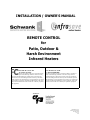
INSTALLATION / OWNER’S MANUAL
REMOTE CONTROL
for
Patio, Outdoor &
Harsh Environment
Infrared Heaters
FCC ID: PUC YCT-107
IC: 4163A-YCT107
This device complies with part 15 of the FCC Rules.
Operation is subject to the following conditions: This device may
not cause harmful interference, and this device must accept any
interference received including interference that may cause undesired operation. The manufacturer is not responsible for any radio or
TV interference caused by unauthorized modification to this equipment. Such modifications could void the user’s authority to operate
the equipment.
FCC ID: PUC YCT-107
IC: 4163A-CMR-1000
This device complies with part 15 of the FCC Rules. Operation is
subject to the following conditions: This device may not cause
harmful interference, and this device must accept any interference
received including interference that may cause undesired operation.
The manufacturer is not responsible for any radio or TV interference
caused by unauthorized modification to this equipment. Such modifications could void the user’s authority to operate the equipment.
MEMBER OF
1
GP-MREM-CX-03A
Remote Control Manual
RD: SEPT 2006
RL: 03A
KH
NOTICE:
The Manufacturer reserves the right to make changes to
equipment and specifications without obligation or notification.
This publication, or parts thereof, may not be reproduced in
any form, without prior written consent from The Manufacturer.
Unauthorized use or distribution of this publication is strictly
prohibited.
Schwank Group
5285 Bradco Boulevard
Mississauga, Ontario,
L4W 2A6
Phone: (905) 712-4766
Fax: (905) 712-8336
1-866-361-0417
InfraSave
Mississauga, Ontario,
Waynesboro,Georgia,
Phone: 1-866-INFRASV (463-7278)
Fax: 1-866-724-9265
http://www.infrasave.com
e-mail: [email protected]
PO Box 988, 2 Schwank Way
Waynesboro, Georgia,
USA 30830
Phone: (706) 554-6191
Fax: (706) 554 9390
1-877-446-3727
e-mail: [email protected]
http://www.schwankgroup.com
2
GP-MREM-CX-03A
Remote Control Manual
RD: SEPT 2006
RL: 03A
KH
REMOTE CONTROL
for
Patio, Outdoor & Harsh Environment
Infrared Heaters
Table of Contents
Features and Specifications …………………………………………
Operation of Remote Controls: Overview ………………………….
Programming / Setup of Receivers & Hand Set Transmitters ………
House Code Set-up …………………………………………...
Unit Code Set-up ……………………………………………..
Graphic: Setup of Receivers & Hand Set Transmitters ………
Sample Patio Control System ……………………………………….
Part Numbers: Remote control Systems …………………………...
Receiver Kit Installation in Heater:
JP-1234-RK: patioSchwank 2300 & IO-210 Series .…………
JP-1234-TK: STW / IW & SPW / IWP Tube Heater Series
Wiring Diagrams:
patioSchwank 2300 & IO-210 Series …………………………
STW / IW & SPW / IWP Tube Heater Series ………………
Patio Sketch & Control Programming Aid …………………………..
3
3
4
4
4
4
5
6
6
7
9
8
11
12
GP-MREM-CX-03A
Remote Control Manual
RD: SEPT 2006
RL: 03A
KH
FEATURES AND SPECIFICATIONS
Receiver - (Model CMR-1000-24V)
Kits: JP-1234-RK: 2300/IO-210 & JP-1234-TK: Tube Heaters
FEATURES:
• ‘House Code’ setting allows unique system “address” - avoids interference with neighboring systems
• Works with Hand Set Transmitter YCT-107
• Easily installed in heater
CONNECTION: (Wiring Diagrams Pages 8 and 11)
• Connect 24V AC Line source to “ L ”
• Connect 24V AC Neutral source to “ N ”
• Connect heater 24V AC Load to “
”
• Connect heater 24V AC Neutral Load to “ N ”
L
N N
IN
IN
OUT OUT
CODE SWITCHES: Adjustable with ‘slot’ type screw driver
• House Code: A to P: Allows interference-free programming unique
from that of a neighboring system; allows use of separate transmitter
hand sets to control different patio areas at the same site
• Unit Code: 1 to 16: Unit Code matches to individual ’On-Off’ buttons
and Group Selection switch on hand set transmitter; Individual code for
each receiver (or zones of heaters / receivers)
House
Code
Unit
Code
Hand Set Transmitter - (Model YCT-107)
JP-1234-HS
OPERATION:
• 4 ‘Groups’ of 4 button sets = 16 On-Off functions
• House Code dial switch = 16 position - located on
reverse side
• Battery: 12V (type 23A) one included
SPECIFICATIONS:
Receiver
Hand Set Transmitter
Frequency
433.92 MHz
433.92 MHz
Power
12/24V +/- 10%; AC 50/60Hz.; or DC
< 26μW
Max. Rating: 7 Amps
Battery: 12V (type 23A)
CAUTION:
For safety, switch off main power before connecting, disconnecting or servicing.
DO NOT OVERLOAD
FCC ID: PUC YCT-107
IC: 4163A-YCT107
This device complies with part 15 of the FCC Rules.
Operation is subject to the following conditions: This device may not
cause harmful interference, and this device must accept any interference received including interference that may cause undesired operation. The manufacturer is not responsible for any radio or TV interference caused by unauthorized modification to this equipment. Such
modifications could void the user’s authority to operate the equipment.
4
FCC ID: CMR-100
IC: 4163A-CMR1000
This device complies with part 15 of the FCC Rules. Operation is
subject to the following conditions: This device may not cause harmful
interference, and this device must accept any interference received
including interference that may cause undesired operation. The manufacturer is not responsible for any radio or TV interference caused by
unauthorized modification to this equipment. Such modifications
could void the user’s authority to operate the equipment.
GP-MREM-CX-03A
Remote Control Manual
RD: SEPT 2006
RL: 03A
KH
OVERVIEW
The remote control hand set is used to turn patio heaters ON and OFF from a distance of up to 25 feet.
Heaters must have a 24V Direct Spark Ignition system designed for automatic control.
One Transmitter Hand Set can control up to 16 individual heaters (receivers) or 16 zones of heaters.
An ‘On-Off’ button must be pressed and held for 2 (two) seconds to activate the heaters/receivers.
There is a ‘purge cycle’ time delay of up to 30 seconds before the heater will ignite.
We recommend that any patio site have at least two Transmitter Hand Sets regardless of the number of heaters – one hand set is a secure back-up if the other is misplaced or malfunctions.
PROGRAMMING / SET UP (Read this section prior to installation of receivers).
•
•
•
Follow the instructions below to set each receiver to the correct House & Unit Codes.
Complete the “Patio Floor Plan sketch and Settings Table” on the last page of this manual to assist you
in the set up process.
Refer to the wiring diagrams in this manual for electrical connection of the receiver to the heater ignition system.
NOTE: THE LETTERS OR NUMERALS ON THE HOUSE CODE AND UNIT CODE ‘DIAL FACES’ INDICATE ONLY EVERY OTHER
OR ‘ODD’ SETTING POSITION. THE IN-BETWEEN ‘EVEN’ POSITIONS ARE REPRESENTED BY A DOT (B,D,F,..) (2,4,6,…).
Setting the House Code – Adjust with slot screw driver
Set the same “house code” on the transmitter and any/all receivers that it is intended to control (16 codes
available A to P). e.g.: If a hand set transmitter is set to house code “B”, all receivers set to house code “B” will be
controlled by that transmitter.
The ‘house Code’ ensures that there will be no interference with any neighboring remote controlled appliances.
This would include the setting of unique House Codes on multiple Transmitter Hand Sets that are used to control
Setting the Unit Code – Adjust with slot screw driver
CORRESPONDING SETTINGS
The Transmitter Hand Set has a ‘Group Selection’ slide switch with 4
settings (I, II, III, IV) and 4 sets ‘On-Off’ buttons (1, 2, 3, 4).
Hence there are four ‘On-Off’ buttons for each Group Setting and a
total of 16 ‘On-Off’ functions on the Hand Set. (see table —>)
RECEIVER
Each receiver has 16 unique ‘Unit Codes’ (numerals 1 to 16). The
“Corresponding Settings” table (to the right —>) indicates the receiver
setting that corresponds to each combination of Group switch and OnOff button on the Transmitter Hand Set.
Set a different ‘Unit Code’ on each receiver so that the Transmitter
Hand Set can control up to individual 16 heaters.
NOTE: Within any zone of a patio best comfort is provided by the operation of two (or more) opposing heaters. All receivers (heaters) located in in the same ‘comfort zone’ can be set to the same ‘Unit Code’.
All heaters in a common ‘comfort zone’ are thereby activated simultaneously by one common ‘On-Off’ switch. (There is no limit to the
number of receivers that can be set to the same Unit Code.)
UNIT
CODE
TRANSMITTER
GROUP
SELECTION
1
2
3
4
5
6
7
8
9
10
11
12
13
14
15
16
I
II
III
IV
ON-OFF
BUTTON
1
2
3
4
1
2
3
4
1
2
3
4
1
2
3
4
Also see next page for a description of setting codes in graphic format.
Complete the “Patio Floor Plan sketch and Settings Table” on the
last page of this manual to assist you in the set up process.
5
GP-MREM-CX-03A
Remote Control Manual
RD: SEPT 2006
RL: 03A
KH
SETTING UNIT CODES AND HOUSE CODES
Transmitter
Front
Unit Codes (16 Positions):
On/Off Switch:
selects Channels
Group I
Group II selects Channels
Group III selects Channels
Group IV selects Channels
1
1
5
9
13
2
2
6
10
14
3
3
7
11
15
4
4
8
12
16
Select a unique unit code for each receiver or zone of
receivers. The combination of
Group & On-Off button selection matches to each unit code
on each receiver.
Transmitter
Back
House
Code
ON
1
ON
2
ON
3
ON
4
I
II
III
Unit
Code
Adjust Code dial
switches with a slot
screwdriver
Front of Transmitter
House Codes (16 Positions):
For each area you wish to control with a separate transmitter, select a unique code from A to P. This avoids interference with neighboring control systems.
Set the same ‘House Code’ on all
Receivers & Transmitter(s) located in the same area.
A
M
E
I
House
Code
Back of Transmitter
Unit
Code
As a secure storage option for the Hand Set Transmitter, a set of Velcro
strips is provided to fasten the Transmitter in a convenient site location.
One Battery: 12V (type 23A) is included with the Hand Set Transmitter.
Replace the battery in the Hand Set each year at the start of the heating season .
6
GP-MREM-CX-03A
Remote Control Manual
RD: SEPT 2006
RL: 03A
KH
Sample Patio Set-up:
Dining patio with 3 zones. Each zone
has 2 opposing heaters that provide best
comfort when operating simultaneously
as a pair. The entire patio area will be
controlled by one Hand Set Transmitter.
H-1
Set all ‘House Codes’ to the same Letter
Code on one Hand Set Transmitter and
six receivers (one in each heater). Heaters H-1 & H-2: Set receiver Unit
Codes to “1” - the hand set transmitter
will activate both heaters in Zone 1 with
Group I / Button 1.
H-3
H-5
ZONE
11
ZONE
22
ZONE
33
H-2
H-4
H-6
Similarly, set receivers in heaters H-3 & H-4 to “2” and H-5 & H-6 to “3”. Both Zone 2 heaters
turn On/Off with button set “2” and both heaters in Zone 3 with button set “3”.
Alternately, for individual control of heaters, set each receiver Unit Code to a unique number
(H-1 to “1”, H-2 to “2”, etc.). Heaters H-1 to H-4 will be controlled by hand set transmitter
Group I - Buttons 1 to 4 and heaters H-5 and H-6 will be controlled by Group 2 - Buttons 1 and 2.
Kits / Part Numbers for Remote Control systems:
NOTE: Items are ordered separately
•
•
•
•
JP-1234-HS REMOTE CONTROL HAND SET – Accessory; single item with Velcro fastener
JP-1234-RK REMOTE CONTROL RECEIVER – LUMINOUS HEATER– Accessory Kit;
Includes: receiver JP- 1234-RC, wires, Velcro Fastener, instructions
JP-1234-TK REMOTE CONTROL RECEIVER – TUBE HEATER – Accessory Kit;
Includes: receiver JP- 1234-RC, 24V Relay JS-0568-KT, wires, Velcro Fastener, instructions
JP-1234- RC REMOTE CONTROL RECEIVER – Part; single item with Velcro fastener
Refer to the enclosed wiring diagrams:
•
•
2300 series Patio Heaters- Luminous Heater
STW / IW & SPW / IWP Patio Heaters – Tube Heater
7
Page 8
Page 10
GP-MREM-CX-03A
Remote Control Manual
RD: SEPT 2006
RL: 03A
KH
RECEIVER KIT INSTALLATION - JP-1234-RK
patioSchwank 2300 / IO-210 Series
•
•
Read the Programming / Setup section (pages 4 & 5) prior to installation of the receiver into a heater.
Complete the “Patio Floor Plan sketch and Settings Table” on the last page of this manual to assist you
in the installation & programming process.
Refer to the wiring diagrams (next page) in this manual for electrical connection of the receiver to the heater
ignition system.
•
NOTE: We recommend the installation of an External Manual Over-ride Switch to allow temporary operation of
the heater(s) if the Hand Set Transmitter is misplaced or malfunctions. (Refer to Wiring Diagram)
The Manual Over-ride Switch must be in the ‘Off” position for the remote control system to operate.
FIGURE 1
1. Remove Control Access Door
4.
5.
Insert/fasten wires into receiver (see Wiring Diagram - next page)
3.
Connect wires from the receiver to the heater (see Wiring Diagram next page)
FIGURE 2
Remove the protective backing from one set of the Velcro strips
Attach one Velcro strip to the inside surface of the Heater - Press
Velcro firmly in place
•
6.
2.
NOTE: Locate Velcro so that the mounted receiver will
not come into contact with existing burner components
Attach the mating Velcro strip to the back side of the Receiver press Velcro firmly in place
FIGURE 3
7. Program the receiver by setting the ‘House Code’ and ‘Group Code’ dial
switches to the correct setting for that particular heater or zone (see pages
4, 5)
8.
Attach the Receiver to the Velcro strip on the inside surface of the heater
9.
Reinstall the Component Access Door on the heater
10. OPTIONAL: For secure storage of the Transmitter, attach second set of Velcro strips to the back of the Hand Set Transmitter
and at a convenient site location.
8
GP-MREM-CX-03A
Remote Control Manual
RD: SEPT 2006
RL: 03A
KH
Wiring Diagram: 2300 / IO-210 series Patio Heaters.
Remote Control Kit: JP-1234-RK
NOTE: Recommended: Installation of an External Manual Over-ride Switch to allow temporary operation of the heater(s) if the Hand Set Transmitter is misplaced or malfunctions.
The switch must be in the ‘Off” position for operation of the remote control system.
9
GP-MREM-CX-03A
Remote Control Manual
RD: SEPT 2006
RL: 03A
KH
RECEIVER KIT INSTALLATION - JP-1234-TK
SPW / IWP Tube Heater Series
(Model STW / IW is shown below—follow the same instructions for SPW / IWP)
•
•
•
Read the Programming / Setup section (pages 4 & 5) prior to installing the receiver into a heater.
Complete the “Patio Floor Plan sketch and Settings Table” on the last page of this manual to assist
you in the installation & programming process.
Refer to the wiring diagram (following these pages) in this manual for electrical connection of the 24V Relay
and receiver to the heater ignition system.
NOTE: We recommend the installation of an External Manual Over-ride Switch to allow temporary operation of
the heater(s) if the Hand Set Transmitter is misplaced or malfunctions. (Refer to Wiring Diagram)
The Manual Over-ride Switch must be in the ‘Off” position for the remote control system to operate.
FIGURE 1
1. Remove burner side panel (electrical cord side) by
removing all fastening screws
2. Remove 2 screws in the end of the housing that
secure the component plate inside the housing
•
3.
NOTE: Retain all screws for reattachment of
component plate & side panel
FIGURE 2
Slide component plate out of
burner housing
FIGURE 3
4. Install the 120V/24V Relay Switch on to the
component plate; align to the predrilled holes
in the plate and fasten with bolts/nuts provided.
5.
10
Connect wiring as indicated in the Wiring Diagram (page 11).
GP-MREM-CX-03A
Remote Control Manual
RD: SEPT 2006
RL: 03A
KH
SPW / IWP Tube Heater Series
RECEIVER INSTALLATION (Continued)
6.
FIGURE 4
Insert the wires provided into the Receiver unit
as per Wiring Diagram (next page).
7.
Remove (snip off) any female spade connectors
from wires from the receiver
8.
Connect wires to the terminal block on the component plate as indicated in the Wiring Diagram
(next page)
9.
Replace component plate in the burner housing,
align with holes in the end of the housing
10. Fasten component plate in place with two screws
at the end of the housing
FIGURE 5
10. Remove the protective backing from one set of the
Velcro strips provided to reveal the adhesive
11. Attach one Velcro strip to the inside surface of the
burner housing side panel—Press firmly in place
•
NOTE: Locate Velcro so that the mounted receiver
will not come into contact with existing burner
components when the side panel is reattached
12. Attach the mating Velcro strip to the back side of
the Receiver—press Velcro firmly in place
FIGURE 6
13. Program the receiver by setting the ‘House Code’ and
‘Group Code’ dial switches to the correct setting for that
particular heater or zone (see pages 4, 5)
14. Attach the Receiver to the Velcro strip on the inside surface
of the housing side panel
15. Reattach the side panel to the burner housing
16. OPTIONAL: For secure storage of the Transmitter,
attach second set of Velcro strips to the back of the
Hand Set Transmitter and at a convenient site location.
11
GP-MREM-CX-03A
Remote Control Manual
RD: SEPT 2006
RL: 03A
KH
Wiring Diagram: SPW / IWP
Tube Heater series Patio Heaters
Remote Control Kit: JP-1234-TK
NOTE: Recommended: Installation of an External Manual Over-ride Switch to allow temporary operation of the heater(s) if the Hand Set Transmitter is misplaced or malfunctions.
The switch must be in the ‘Off” position for operation of the remote control system.
12
GP-MREM-CX-03A
Remote Control Manual
RD: SEPT 2006
RL: 03A
KH
13
GP-MREM-CX-03A
Remote Control Manual
RD: SEPT 2006
RL: 03A
KH
HEATER
‘TAG’
1
2
3
4
5
6
7
8
9
10
11
12
13
14
15
16
RECEIVER
SET UNIT
CODE TO
IV
III
II
I
1
2
3
4
1
2
3
4
1
2
3
4
1
2
3
4
TRANSMITTER
GROUP
ON-OFF
SELECTION
BUTTON
CORRESPONDING SETTINGS
Complete this “Settings Table” to assist in
the set up of receivers and assignment of
Hand Set control buttons to heaters.
2. It is recommended that any patio site have a
spare or back-up Hand Set Transmitter that can
be put into service if a first Hand set malfunctions or is misplaced. Set up any spare or backup hand set(s) to the same ‘House Code’ as the
first hand set.
1. Set the ‘House Code’ of any receiver to the
same ‘House Code’ setting on the hand set that
will control it.
NOTE:
LEAVE A COPY OF THIS SHEET WITH THE END-USER
Use this area to sketch a ‘Floor Plan’ of the patio and heater layout. Assign a number
or letter ‘tag’ to each heater (or pair of heaters) to assist in the set up of receivers.