1
Miter Saw
255 mm (10”)
MODEL LS1020
Equipped with Electrical Blade Brake
INSTRUCTION MANUAL
DOUBLE
INSUL ATlON
SPEC IFICAT IONS
‘
Manufdcturer reserves the right to chdnye specifications w i t h o u t notice
4
Note Specifications m a y differ from country to country
For Your Own Safety Read Instruction
Manual Before Operating Miter Saw
GENERAL SAFETY PRECAUTIONS
(For All Tools)
1. KNOW YOUR POWER TOOL. Read the owner’s manual carefully. Learn the
tools applications and limitations, as well as the specific potential hazards
peculiar t o it.
2. KEEP GUARDS IN PLACE and in working order.
3. REMOVE ADJUSTING KEYS AND WRENCHES. Form habit of checking t o
see that keys and adjusting wrenches are removed f r o m tool before turning
it on.
4. KEEP WORK AREA CLEAN. Cluttered areas and benches invite accidents.
5. DON’T USE IN DANGEROUS ENVIRONMENT. Don‘t use power tools in damp
or wet locations, or expose t h e m t o rain. Keep work area well lighted.
6. KEEP CHILDREN AWAY. All visitors should be kept safe distance from work
area.
7. MAKE WORKSHOP KID PROOF with padlocks, master switches, or by
removing starter keys.
8. DON’T FORCE TOOL. It will do the job better and safer at the rate for which
it was designed.
9. USE RIGHT TOOL. Don’t force tool or attachment t o do a job for which
it
was not designed.
IO. WEAR
PROPER APPAREL. Wear n o loose clothing, gloves, neckties, rings,
bracelets, or other jewelry w h i c h may get caught in moving parts. Nonslip
footwear is recommended. Wear protective hair covering t o contain long hair.
11. ALWAYS USE SAFETY GLASSES. Also use face or dust mask if cutting operation is dusty. Everyday eyeglasses only have impact resistant lenses, they
are NOT safety glasses.
12. SECURE WORK. Use clamps or a vise t o hold work when practical. It’s safer
than using your hand and it frees b o t h hands t o operate tool.
13. DON’T OVERREACH. Keep proper footing and balance at all times.
14.MAINTAIN TOOLS WITH CARE. Keep tools sharp and clean for best and
safest performance. Follow instructions for lubricating and changing accessories.
15. DISCONNECT TOOLS before servicing; when changing accessories such as
blades, bits, cutters, and the like.
16. REDUCE THE RISK OF UNINTENTIONAL STARTING. Make sure s w i t c h is
in o f f position before plugging in.
2
17. USE RECOMMENDED ACCESSORIES. Consult the owner's manual for
recommended accessories. The use of improper accessories may cause risk
of injury t o persons.
18. NEVER STAND ON TOOL. Serious injury could occur if the tool is tipped or
if the cutting tool is accidentally contacted.
19. CHECK DAMAGED PARTS. Before further use of the tool, a guard or other
part that is damaged should be carefully checked t o determine that it will
operate properly and perform its intended function - check for alignment
of moving parts, binding of moving parts, breakage of parts, mounting, and
any other conditions that may affect its operation. A guard or other part
that is damaged should be properly repaired or replaced.
20. DIRECTION OF FEED. Feed work into a blade or cutter against the direction
of rotation of the blade or cutter only.
21. NEVER LEAVE TOOL RUNNING UNATTENDED. TURN POWER OFF. Don't
leave tool until it comes t o a complete stop.
22. When servicing use only identical replacement parts.
VOLTAGE WARNING: Before connecting the tool t o a power source (receptacle,
outlet, etc.) be sure the voltage supplied is the same as that specified o n the
nameplate of the tool. A power source w i t h voltage greater than that specified
for the tool can result in SERIOUS INJURY t o the user - as well as damage t o
the tool. If in doubt, DO NOT PLUG IN THE TOOL. Using a power source w i t h
voltage less than the nameplate rating is harmful t o the motor.
3
ADDITIONAL SAFETY RULES
1 . Wear eye protection.
2. D o not operate saw w i t h o u t guards in place.
3. Don’t use the tool in the presence of flammable liquids or gases.
4.Check the blade carefully for cracks or damage before operation. Replace
cracked or damaged blade immediately.
5. Use only flanges specified for this tool.
6. Be careful not t o damage the arbor, flanges (especially the installing surface) or bolt. Damage t o these parts could result in blade breakage.
7. Make sure that the turn base is properly secured so it will not move during
operation.
8. For your safety, remove the chips, small pieces, etc. from the table t o p before operation.
9. Avoid cutting nails. Inspect for and remove all nails from the workpiece before operation.
IO. Make sure the shaft lock is released before the s w i t c h is turned on.
1 1 . Be sure that the blade does n o t contact the turn base in the lowest position.
12. Hold the handle firmly.
13. Do not perform any operation freehand.
14.Keep hands out of path of saw blade.
15. Never reach around saw blade.
16. Make sure the blade is not contacting the workpiece before the s w i t c h is
turned on.
17. Before using the tool o n an actual workpiece, let it run for a while. Watch
for vibration or wobbling that could indicate poor installation or a poorly
balanced blade.
18. Wait until the blade attains full speed before cutting.
19. Stop operation immediately if you notice anything abnormal.
20. Do not attempt t o lock the trigger in the o n position.
21. Shut o f f power and wait for saw blade t o stop before servicing or adjusting
tool.
22. Don’t abuse cord. Never yank cord t o disconnect it from the receptacle. Keep
cord away f r o m heat, oil, water and sharp edges.
SAVE THESE INSTRUCTIONS.
4
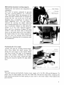
Handle latch
This tool i s equipped with a handle latch
which is used to lock the handle in the
lowered .position. To release from the
lowered position, lower the handle slightly
and turn the handle latch to the released
position. To lock the handle in the lowered
position, lower the handle fully and turn
the handle latch to the locked position.
When carrying the tool, lock the handle in
the lowered position and secure the turn
base by means of the grip.
Bench mounting miter saw
This tool should be bolted with two bolts
to a level and stable surface using the bolt
holes provided in the tool's base.
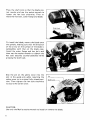
Removing or installing saw blade
CAUTION :
Always be sure that the tool i s switched off and unplugged before removing or installing
the blade.
To remove the blade, use the socket wrench
to loosen the hex bolt holding the center
cover by turning it more than three turns
counterclockwise. Raise the safety cover
and center cover.
5
Press the shaft lock so that the blade cannot revolve and use the socket wrench to
loosen the hex bolt clockwise. Then remove the hex bolt, outer flange and blade.
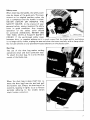
To install the blade, mount the blade onto
the spindle, making sure that the direction
of the arrow on the surface of the blade i s
compatible with that on the blade case.
Install the outer flange and hex bolt, and
then use the socket wrench to tighten the
hex bolt securely counterclockwise while
pressing the shaft lock.
Slip the pin on the safety cover into the
slot in the guide arm while returning the
safety cover to i t s original fully closed position. Then tighten the hex bolt clockwise
to secure the center cover.
I
Pin
CAUTION :
Use only the Makita socket wrench to install or remove the blade.
6
Safety cover
When lowering the handle, the safety cover
rises by means of the guide arm. The cover
returns to i t s original position when the
cut i s completed and the handle is raised.
NEVER DEFEAT OR REMOVE THE
SAFETY COVER. In the interest of your
personal safety, always maintain the safety
cover in good condition. Any irregular
operation of the safety cover should
be corrected immediately. N E V E R USE
THE TOOL WITH A FAULTY SAFETY
COVER. If the see-through safety cover
becomes dirty, or sawdust adheres to it in such a way that the blade and/or workpiece
i s no longer easily visible, unplug the saw and clean the cover carefully with a damp cloth.
Do not use solvents or any petroleum-based cleaners on the plastic cover.
Dust bag
The use of the dust bag makes cutting
operations clean and dust collection easy.
T o attach the dust bag, fit it onto the dust
nozzle of the blade case.
When the dust bas is about half full, re-
1
I
I
I
Fastener
7
Switch action
To prevent the trigger from being accidentally pulled, a lock-off button is provided
as a safety feature.
To start the tool, press in the lock-off
button and pull the trigger. Release the
trigger to stop.
CAUTION :
0
Before plugging in the tool, always check to see that the trigger switch actuates properly
and returns to the "OFF" position when released.
When not using the tool, remove the lock-off button. This prevents unauthorized operation.
Kerf board
This tool i s provided with the kerf board
in the turn base. I f the kerf groove has not
yet been cut in the kerf board by the
factory, you should cut the groove before
actually using the tool to cut a workpiece.
Switch on the tool and lower the blade
gently to cut a groove in the kerf board.
8
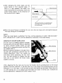
Maintaining maximum cutting capacity
Unplug the tool before any adjustment i s
attempted.
This tool i s factory adjusted to provide
the max. cutting capacity for a 255 mm
( I O ” ) saw blade. When the diameter of the
blade has been reduced due to sharpening,
loosen the hex nut a t the rear of the gear
housing. Use a screwdriver to adjust the
depth adjusting bolt. The saw blade i s
lowered by turning the depth adjusting
bolt counterclockwise and raised by turning it clockwise. Adjust so that when the
handle is in the fully lowered position,
there will be a distance of about 122 mm
(4-3/4”) from the front face of the guide
fence to the point where the front edge of
the blade enters the kerf. Now tighten the
hex nut with the wrench while carefully
holding the adjusting bolt in position with
the screwdriver.
Positioning for miter angle
Loosen the grip by turning counterclockwise. Press down the latch spring. This
allows the turn base to turn freely. When
you have moved the grip to the position
where the pointer indicates the desired
angle on the miter scale, release the latch
spring and securely tighten the grip clockwise.
GI in
NOTE :
The latch spring automatically locates miter angles of 0, 15, 22.5, 30 and 45 degrees. To
select one of these angles, turn the turn base near the desired angle while releasing the
latch spring and allow the latch spring to seat itself in the miter notch. Then tighten the
grip securely.
9
Securing workpiece
By turning the knob on the vise counterclockwise, the screw i s released and the vise shaft
can be moved rapidly in and out. By turning the knob clockwise, the screw remains
secured. To grip workpieces, turn the knob gently clockwise, until the projection reaches
i t s topmost position, then fasten securely. If the knob is forced in or pulled out while
being turned clockwise, the projection may stop a t an angle. In this case, turn the knob
back counterclockwise until the screw i s released, before turning again gently clockwise.
I
Clockwise
I
CAUTION :
Grip workpieces only when the projection
is a t the topmost position. Otherwise the
workpiece cannot be properly gripped and
might pop out or damage the blade.
(Dangerous way to grip workpiece)
When making miter cuts of 30 degrees or more to the side that the vise i s mounted, the
safety cover movement may be slightly obstructed by the vise. I f this situation occurs,
re-mount the vise on the other side of the tool’s base.
10
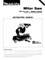
Operation
When cutting with this tool, the thickness
of the blade is cut as well. Therefore, your
cutting line should be on either the left or
right side of the groove in the kerf board.
Switch on the tool and wait until the blade
attains full speed before lowering gently
into the cut. When the blade contacts the
workpiece, gradually bear down on the
handle to perform the cut. When the cut i s
completed, switch off the tool and WAIT
UNTIL THE BLADE HAS COME TO A
COMPLETE STOP before returning the
balde to i t s fully elevated position. A thincut piece could otherwise contact the
coasting blade and be thrown around dangerously.
Fence plate
The fence plate is designed to prevent smaller cutting scraps from jamming inside the
blade case. The fence plate moves right or left automatically as the turn base i s rotated.
Wood facing
Use of wood facing helps to assure splinterfree cuts in workpieces. Attach a wood
facing to the guide fence using the holes in
the guide fence.
CAUTION :
Use straight wood of even thickness as the wood facing.
*See the fiqure below concerning the dimensions of a suggested wood facing.
Over
10 mm+
'3'8"'
11
;
I
I
I
I
450 mm (17-3/4")-
le- -Over
-f
- - - -70 mm
0-
mm+
k 1 0 2 mm-102
I
(4")
,
(4")
-35-mm (2-3/4")
- -(1-3/8")
- - - - -4-
- -- - --
I
Use screws to attach the wood facing to the guide fence. The screws should be installed
so that the screw heads are below the surface of the wood facing.
11
.After changing the miter angle, cut the
wood facing a t that selected angle. I f
there is a gap between the blade, the
wood facing and the workpiece, move the
wood facing slightly in the direction of
the arrow and cut it again.
I
Blade
-\
Wood facing
Wood facing
iJ---
Workpiece
\ \
There should be no gap between
the blade, the wood facing and
the workpiece.
When the wood facing i s attached, do not turn the turn base with the handle lowered.
The wood facing will be damaged.
NOTE :
When the wood facing i s attached, the max. cutting capacities in width (122 mm/4-3/4”
a t 0”, 90 mm/3-1/2” a t 45”) will be reduced by thickness of the wood facing.
Adjusting for smooth handle action
The hex lock nut holding together the gear
housing and arm has been factory adjusted
to assure smooth handle action up and
down and to guarantee precise cutting. Do
not tamper with it.
Should looseness develop a t the gear housing and arm connection, perform the following adjustment. Work the handle up
and down while tightening the hex lock
nut; the best position to tighten the hex
lock nut is just before the motor body
weight i s obvious.
After adjusting the hex lock nut, be sure the handle returns automatically to the initial
position from any position. I f the hex lock nut is too loose, the cutting accuracy will be
affected; if it i s too tight, it will be hard to work the handle up and down. Note that this
i s a self locking nut; it i s a special type that does not loose in normal use. It should not
be overtightened or replaced with other types of nuts.
12
Alignment for squareness
This tool was carefully adjusted and aligned for squareness of cut a t the factory, but
rough handling may have affected the alignment. I f your tool is not aligned properly,
perform the following.
Loosen the grip and set the turn base a t
zero degree by turning the turn base and
allowing the latch spring to seat itself in
the miter notch.
I f the pointer on the indication plate i s not
a t zero on the miter scale, gently tighten
the grip and then loosen the screws on
the indication plate. Adjust the indication
plate so that the pointer will be a t zero on
the miter scale. Then tighten the screws
on the indication plate. Tighten the grip
securely and loosen the hex bolts on the
guide fence. Square the side of the blade
with the side of the guide fence using a
triangular rule; try-square, etc. Then securely tighten the hex bolts on the guide fence.
Installing holders and set plate
The holders can be installed on either side
as convenient means to hold long workpieces or workpieces to be cut continuously into fixed lengths. Fit the set plate on
the holder so that the flat side of the plate
is on the inside, with the curved portion
of the holder pointing up. Then slip the
holder rods into the holes in the base.
Tighten securely with the wing bolt.
-
Wing bolt
13
Cutting fixed lengths
When cutting several pieces of stock to the same length, ranging between 250 - 400 mm
(10" - 15-3/4"), use of the set plate will facilitate operation. Align the cutting line on
your workpiece with either the left or right side of the groove in the kerf board, then
move the set plate flush against the end of the workpiece and secure the set plate with the
screw.
When cutting 2 x 4 (1-5/8" x 3-1/2")
Cuts of 45 degrees can be done as usual as
long as the workpiece is not positioned vertically. To cut vertically positioned workpiece, insert a space block or scrap of wood
measuring 1/2" (12 mm) in thickness between the workpiece and the guide fence.
Carrying tool
When carrying the tool, lower the handle
fully and turn the handle latch to the
locked position. Also secure the turn base
by means of the grip. The tool can then be
conveniently carried by the carrying handle.
14
Guide fence
MAINTENANCE
CAUTION :
Always be sure that the tool is switched off and unplugged before attempting to perform
inspection or maintenance.
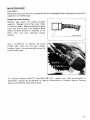
Replacing carbon brushes
Remove and check the carbon brushes
regularly. Replace when they wear down
to the limit mark. Keep the carbon brushes
cl ean and free t o slip in the holders. Both
carbon brushes should be replaced a t the
same time. Use only identical carbon
brushes.
/
Limit mark
Use a screwdriver to remove the brush
holder caps. Take out the worn carbon
brushes, insert the new ones and secure the
brush holder caps.
To maintain product SAFETY and RELIABILITY, repairs, any other maintenance or
adjustment should be performed by Makita Authorized or Factory Service Centers,
always using Makita replacement parts.
15
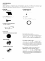
ACCESS0 R I ES
CAUTION :
These accessories or attachments are recommended for use with your Makita tool specified in this
manual. The use of any other accessories or attachments might present a risk of injury t o persons. The
accessories or attachments should be used only in the proper and intended manner.
Dust bag
0
Part No. 12231 9 - 8
Lock-off button (2 pes.)
Part No. 782212-4
0
Part N O ,41 1478-6
0
Socket wrench 13
Ring (16)
Part No. 257022-3
For a 25 m m (31/32") arbor hole
Holder set (with wing bolts)
Part No. 191550-7
0
Saw blades
Chisel tooth combination saw blade
For r i p and cross-cut work.
Most frequently used for general carpentry
Part No
NO
D la
("1
Holedla
lmml
No
teeth
Miter saw blade
For smooth cutting of wood
~
Part No
792078-4
*
NO
D,a
Holedia
No
lmml
lmml
teeth
I ' 2 5 5 - 4 A I 255 110") 1 25 131132"l I 100
When cutting a l u m i n u m , use a cutting lubricant
Carbide-tipped saw blade
Fast, smoother, longer sawing without blade
sharpening. Cuts wood, dry wall, plastics.
Part No
NO
Holedla.
In"
No.
teeth
792200-3
255-11D
255 11O"l
15.88 1518")
50
792303 3
* 255 11C
255 11O"l
15.88 1518")
70
. For alumtnum cutting
16
D la
lmml
Juri
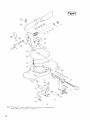
11
RIUS
255 mm (IO”)
MITER SAW
Model LS1020
17
18
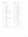
ITEM
NO
NO
USED
DESCRIPTION
.
19
MAKITA LIMITED ONE YEAR WARRANTY
Warranty Policy
I.very Xlakita tool I* thoroughly inspected and tested before leaving the factory. I t is warranted to
be free of defects from worknunship and materials for the period o f ONI, Y t A R froin the date of
original purchase. Should any trouble develop during this one-year period, return the COMPLITF.
tool. freight prepaid, to one of Makita’s P‘actory or Authorized Service Centers. If inspection shows
the trouble is caused by defective workmanship or material, Makita will repair (or at our option,
replace) without charge.
This Warranty does not apply whcre:
repairs have been made or attempted by others:
repairs are required because of nonnal wear and tear
T h e tool has been abused, misused or improperly maintained,
:iltcrations have been made t o the tool.
IN NO 1:VINT SHALL MAKITA Bt. LIABLI FOR ANY INDIRICT, INCIDENTAL OR CONS I Q r l I N T l A L D A M A G I 3 kKOM THI’ SALI: OR USk 01. THI PRODUCT. THIS DISCLAIM1 K
A P P L l t S BOTH DURING AND ATT1:R T H h TI-RM O F THIS WARRANTY.
MAKITA DISCLAIMS LIABILITY I;OK A N Y IMPLIID WARKANTII.S, INCLUDING IMPLIID
WARRANTII-S 01. “MIRCHANTABILITY” A N D “FITNESS I:OR A SPI.CII:IC PIIRPOSI.,”
A1.TI.R Tilt' O N I - Y I A R TFRM 01’ THIS WARRANTY.
i
Tlu\ Warranty gves you specitic l e ~ a lrlyht3, and you may also llavc other rights which vary froni
state to state Some states d o not allow the exclusion or limitation of incidental or consequential
damages. so the above Iimitatiorl or exclusion may not apply to you Sonic states d o not allow
limitation on tiow long a n implied warranty lasts, so the above limitation may not apply to you.
--f-Q---_P--*P-*O-PIP-9
Makita Corporation
3-11-8, Sumiyoshi-cho,
Anjo, Aichi 446 Japan
8835898063
PRINTED IN JAPAN
1991 - 6 - N