1
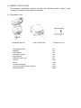
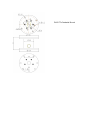
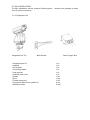
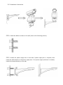
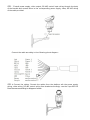
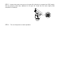
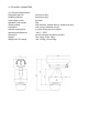
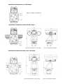
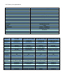
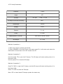
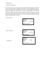
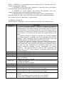
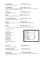
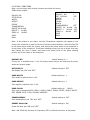
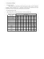
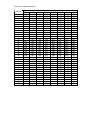
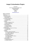
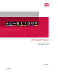
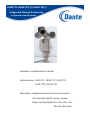
DLM1771-DLM1772(Y)-DLM1775(Y)
Integrated Camera Positioning
w/Optional Dual IR Lamps
Installation and Operations Manual
Model Number: DLM1771, DLM1772, DLM1775,
DLM1772Y, DLM1775Y
Description: Integrated Camera Positioning System
with optional dual IR Lamps, Heater,
Wiper and Day/Night 18x, 23x, 26x, 30x,
35x and 36x Zoom
Table of Contents DLM1771-DLM1772_DLM1775 and
DLM1772Y-DLM1775Y with optional dual IR Lamps
page
1. Installation
3
1.1 Foreword
3
1.2 Outline
3
1.3 Safeguards and Warnings
3
1.3.1 Functions and Features
3
1.3.2 Function Descriptions
4
2. Preparation for Installation
7
3. Installation Warnings
3
3.1 Pedestal Installation
8
3.1.1 Equipment List
8
3.1.2 Installation Instructions
9
Wiring Diagram
10
3.2 Wall Installation
13
3.2.1 Equipment List
13
3.2.2 Installation Instructions
14
Wiring Diagram
15
4. Technical Parameters
17
4.1 Structure
Mechanical Diagram
17
18
4.2 Rotating parameters
19
4.3 Electrical parameters
19
4.4 Camera parameters
19
4.5 IR Lamp Parameters
20
5. Operation
22
5.1 Basic Descriptions
22
5.2 Operation Procedures
23
5.3 Preset Functions
24
5.4 Screen Character Display
24
5.5 PTZ Functions
25
5.6 Function Descriptions
25
6. Menu Operations
25
6.1 Menu Operation Instructions
26
6.4 Camera Menu
28
6.6 Pan/Tilt Menu
30
6.7 Initialization (Powering Up)
31
6.8 Privacy Zone
32
6.9 Alarms
34
6.10 Auxiliary (Wiper and IR Lamp)
34
6.11 Reset Camera
34
6.12 Washer/Wiper Function and Wiper Controls
34
6.13 Menu for DLM1771 with Hitachi 1/3” CCD 18x D/N Camera
35
7. Dip Switch Settings
36
7.1 Pan Tilt Controls
36
7.2 Switch SW1 Protocols, Camera Modules, Baud Rate Settings
36
7.3 Switch SW2 Receiver/Driver Settings (P and D Protocols)
37
Appendix A Troubleshooting
39
A.1 Video Image
39
A.2 PTZ Controls
39
A.3 Installation
40
1. INSTALLATION MANUAL
1.1 FOREWORD
This manual introduces the function, installation and operation of the integrated high
speed pan tilt camera in details. Please thoroughly familiarize yourself with the
information in this manual prior to installation.
This series pan tilt camera is specially designed for airports, homeland security,
customs, highway etc. It has many features: reliable, stable, airproof, waterproof, acid
water proof, able to withstand high temperature, aging, strong wind and so on. It adapt
to the following harsh conditions, such as high wind power, wide changing temperature
conditions, high electromagnetism and lightning and continuous operating conditions.
This series integrated positioning system includes high speed decoder, pan tilt, shield,
heater, defroster, wiper and integrated DSP ((digital signal processing) camera module
day/night 23x, 26x, 36x optical and 12x digital zoom.
Protocol P/D is employed in the received driver of the integrated positioning system. It
may support standard system platforms such as keyboards and matrix switchers. This
manual will not explain the operation of other devices if connecting with system, please
read the manual of the interfacing product or device.
1.2 OUTLINE
1.3 SAFEGUARD AND WARNINGS
Prior to installation and use of this product, please note the following WARNING. This
product may be only used in specified range in order to avoid any damage or danger.
Installation and servicing should only be done by qualified service personnel;
It may not be used in temperature range, humidity and power supply outside
the specifications.
Only use replacement parts recommended by factory.
Please use soft cloth to clean the glass. Use neutral cleaner if smear is present
on the glass. No use of strong or corrosive cleanser to avoiding scuffing.
Be cautious when moving P/T unit, never press the drive parts heavily to avoid
pan tilt camera troubles.
The installation bracket should be capable of supporting four times the total
weight of the integrated camera.
Please thoroughly read this manual prior to installation and operation.
1.3.1 FUNCTIONS AND FEATURES:
Pan tilt camera is made of high strength all-alloy material, waterproof, and able to
withstand high temperature, aging, and corrosion.
Accurate motor driving, stable operation, sensitive reaction and accurate
orientation
Includes built-in function menu, to set camera and pan/tilt parameters.
Features video freeze, back light compensation function
Pattern track memory function, may record the preset transfer and all standard
P/T/Z track
Change speed proportionally - Pan/tilt speed and the depth of zoom lens decline
proportionally
128 preset position, with accuracy error less than 0.10
Preset target speed: 1500 /sec for pan, 800 /sec for tilt
Manual control speed: 0.1~1000/sec for pan control, 0.1~800/sec for tilt
Alterable auto scan speed: 10~400 /sec may be set by the in-built menu
8 preset tour functions, dwell time may be set to 2- 60sec
Pan rotation: 3600 continuously rotating
Tilt rotation: -85~ +350 rotation, with auto flip function
Manual control speed for pan: 0.10 ~1000/sec
Manual control speed for tilt: 0.10 ~800/sec
Video output: PAL/ NTSC format, composite video: 1V p-p
Baud rate: 1200/2400/4800/9600 Baud
RS-485 communication for control of pan tilt
IR Illuminator for night vision to 100 meters
Built-in wiper, heater, fans, defrost module
Washer Wiper Preset Linkage
Embedded surge and lightning circuitry
Complies with CE, FCC and IP66 standards,
Working temperature: -40 °C ~ +50 °C
1.3.2 FUNCTION DESCRIPTIONS
Screen menu function (OSD)
It has screen menu function. All information of camera and pan& tilt may be displayed
by menu and to set the function and parameter
Multi-camera control function
Select different camera only by mending dial switch setting, no any hardware or
software needed. It supports SONY, HITACHI cameras and so on.
Proportional pan
Horizontal and tilt speed change automatically with the zoom changes. When zooming
wide, the camera speeds down; then zooming narrow, the camera speeds up to catch
better tracing effect.
Auto scan
Auto scan refers to the function of 3600 continuous scan the images at certain speed
on the horizontal lever when keeping the pitching angle unchanged. The left and right
limits may be set for continuous scan at certain speed on the horizontal lever.
Auto Flip
When the camera tilts downward and goes just beyond the vertical poison, the dome
rotates 180°. When the dome rotates, the camera starts moving upward as you
continue to hold the joystick in the down position. Once you let go of the joystick
after the dome rotates, joystick control returns to normal operation. The auto flip
function is useful for following a person who passes directly beneath the camera.
Preset
Any position of dome camera PTZ may be conserved. We call it preset
(pre-established position). The preset may be transferred and cleaned.
Preset Tour
The dome camera will transfer pre- established preset 1-8 every 10 second. It will
leap over to next preset position if position in not among 1-8.
Pattern
The PTZ orientation move track of the camera may be stored, we call it pattern. The
pan & tilts UP, DOWN, LEFT, RIGHT and the lens FAR, NEAR may be stored. Also we
may call the presetting. This function may be used to record and simulate the
operator’s operation process.
Zero Test
The camera will turn to horizontal and tilt zero by preset 34 when the inevitable
desynchronizing appears or the operator wants to find zero position during working
process. It may reset the orientation and is convenient for operator
Low LUX (colors/ black & white swift) function
The camera automatically changes CCD LUX according to surrounding light. Color
image changes to black& white one in low LUX; black & white image changes to color
one in high LUX (related to camera)
Auto focus
The camera automatically adjusts lens focus to keep clear image if auto focus mode.
Manually operate FAR or NEAR focus adjustment may also adjust focus. The dome
camera will recover auto focus adjustment function if operate horizontal, vertical
rotation or control lens zoom.
Auto iris function
The camera automatically adjusts iris to keep normal brightness in auto iris mode.
Manually operate OPEN or CLOSE iris adjustment button may also adjust iris. The
dome camera will recover auto adjustment function if operate horizontal, vertical
rotation or control lens zoom.
Backlight compensation
The object will become black as the shadow if strong light appears in background.
Backlight compensation function may compensate the brightness automatically to
dark objects in bright light background and adjust the brightness background to avoid
the image full of brightness and get clear image. Too strong backlight may make the
object illegibility.
WDR (Wide Dynamic Range)
If there is quite dark and quite bright in the image, on Hitachi 30x and 35x, Sony 36x,
WDR may make the darkest and brightest balance to keep clear image
Privacy masking function:
The user may set the region which may not be seen by the operator. The region which
has been covered will move together with the pan tilt direction, change together with
the size of the image, and cover the region which need to be invisible always.
Options for wiper control:
:
By OSD menu, the wiper may be controlled by three ways: (1)single-control mode:
The wiper will stop after 15 sec when receiving the control instruction. (2)Circle
startup mode: When receiving the control instruction, the wiper will run for 5 sec,
then stop for 15 sec. And it will not stop until it receives the control instruction for
stop.(3)Linkage mode: when receiving the control instruction, there will be a linkage
with the AUX switch, and the function of 65 preset will be carried on.
2.2. PREPARATION FOR INSTALLATION
1) All electric working must be accorded to latest electric, fire proof and related
specifications
2) Be sure all accessories are included as packing list and application and installation
requirements. If not, please contact with supplier.
3) Be sure the product is suitable for the working environment.
4) Check installation space.
Make sure there is enough space for the product and accessory.
Make sure the wall may afford 4 times of the speed dome camera and accessories.
5) Preparation of cable
Use video cable according to transmitting distance. Specification of video coaxial
cable features:
a) 75 ohm resistance
b) copper core cable
c) 95% copper shield.
2.3 INSTALLATION WARNINGS
1) Prior installation, read the instruction carefully.
2) To use the power supply and voltage as the label instruction of cable, standard
voltage is 18VAC, 24VDC, 230VAC are available versions.
Long time excess high or low voltage will cause damage of speed dome camera.
Electric power must be kept over 50W (3.5A with IR Lamps), otherwise abnormal
reset and erratic movement may result.
3) Don’t aim the lens at high light object, otherwise CCD will abate and no image or
image fuzzy.
3.1 PEDESTAL INSTALLATION
The pedestal installation camera includes the following parts. Inspect each
package to make sure all parts are present.
3.1.1 Equipment List
Integrated pan tilt
Power Supply Box
Integrated pan tilt
pedestal
wall bracket
connecting cables
fixed spanner
pedestal water joint
manual
Glove
Thread compound
Fixed screw Φ5X10mm (platform)
Φ8X38mm bolts
Pedestal mount
1
1
1
1
1
1
1
1
1
4
4
pc
pc
pc
pc
pc
pc
set
pair
roll
pcs
sets
3.1.2 INSTALLATION INSTRUCTIONS
STEP 1 Locate the floor or impending base level that may support 4 times the weight of
pan tilt. Fix the screws provided on the floor or firm surface.
STEP 2 fix the pedestal on the floor or impending base level:
STEP 3 Install power supply, video output, RS-485 control input wiring through waterproof
connector plugs, and connect them to the corresponding power supply, video, RS-485
wiring of the cable provided.
Connect the cable according to the following pinout diagram:
STEP 4
Fix the four Φ5x10 fixed screws on the pedestal, then install the connecting cable
into the pedestal and screw it with waterproof BNC plugs.
STEP 5 Loosen the screw nut cover on the pan tilt’s left side, to expose the 8 DIP dial
switch. Set the protocol, baud rate, address for the pan tilt. Screw the nut cover tightly
after completion of settings.
STEP 6
Turn on the power to check operation.
DLM177x Pedestal Mount
1
* Inverted View of mount
* Maximum Bearing Weight 100Kg
* Aluminum alloy material
1. Rubber Gasket for top of pole
2. Cable Gland cover
3. Top of mount for installing
DLM177x Integrated camera system
3
2
Dimensional Drawing: (unit: MM)
DLM177x Pedestal Mount
3.2 WALL INSTALLATION
The wall installation camera contains following parts. Inspect each package to make
sure all parts are present.
3.2.1 Equipment List
Integrated Pan Tilt
Wall Bracket
Integrated pan tilt
pedestal
wall bracket
connecting cables
fixed spanner
pedestal water joint
manual
Glove
Thread compound
Fixed screw Φ5X10mm (platform)
Φ8X38mm bolts
Power Supply Box
1
1
1
1
1
1
1
1
1
4
4
pc
pc
pc
pc
pc
pc
set
pair
roll
pcs
sets
3.2.2 Installation Instructions
STEP 1 Install the Φ8mm screws on the wall (refer to the following picture)
STEP 2 Install the power supply box on the wall if power supply box is required, then
install the wall bracket on the power supply box. If no power supply enclosure is needed,
install the bracket directly on the wall.
STEP 3 Install power supply, video output, RS-485 control input wiring through the body
of the bracket and connect them to the corresponding power supply, video, RS-485 wiring
of the cable provided.
Connect the cable according to the following pinout diagram:
STEP 4 Connect the cables. Connect the cables from the platform wih the power supply
wiring, video wiring, RS-485 control wiring from bracket accordingly- use the 4 pcs Φ5×10
fixed screws according to diagram below.
STEP 5 Loosen the screw nut cover on the pan tilt’s left side, to expose the 8 DIP switch.
Set the protocol, baud rate, address for the pan tilt. Screw the nut cover tightly after
completion of settings.
STEP 6
Turn on the power to check operation
4. TECHNICAL PARAMETERS
4.1 Structure parameters:
Integrated pan tilt
Rotating platform
Load weight mode
standard Load weight
Shield module
installation
bracket requirement
operating temperature
Dimension
Weight
Weight with IR Lamps
Aluminum alloy
Aluminum alloy
top bear
5Kg
with housing, defrost device, heater and fans
wall mount, pedestal mount
4 times of the pan tilt’s weight
-40ºC ~ 50ºC
as the following dimension picture
Net 14Kg; Gross 18Kg
Net 16.5Kg; Gross 19Kg
Installation dimensions (no IR Lamps):
DLM1771-DLM1772-DLM1775
Installation dimensions with LED IR Lamps
front view dimensions w/ IR (LED)
side view dimension diagram
Installation dimensions with Laser IR Lamps
front view dimensions w/ IR (Laser)
side view dimension diagram
4.2 Rotating parameters:
Pan rotation
Tilt rotation
Manual control speed
Pan
Tilt
Preset speed
Pan
Tilt
4.3 Electrical parameters
Input voltage
Input power
Coaxial cable requirement:
Heater, defroster, fan, wiper
360ºcontinuous rotation
+35º ~ -85º unobstructed rotation
0.1º ~ 100º/Second manual operation
0.1º ~ 80º/Second manual operation
80º/ Second
40º/Second
18VAC, 24VDC, 230VAC, 50/60Hz
50W; 70W with IR Lamp
75 ohms resistant; complete copper core conductor;
complete copper shield layer, shield cover range 95%
4.4 Camera, lens parameters
DLM1771 - 18X Day/Night
Camera Specifications
Image Sensor
1/3” Hitachi CCD
Resolution
540 TVL
TotalPixels
NTSC 380k / PAL 470k
Signal Format
NTSC/PAL
Video Output
1V p-p (sync negative)
Lens
18X optical
Focal Length
f=4.7mm(Wide)~84.6mm(Tele)
Aperture
F1.6~F2.8
Digital Zoom
12X
Min. Working Distance
54.7mm(Wide)~310mm(Tele)
Sync System
internal/external (V-lock)
S/N Ratio
>50dB
Min. Illumination
0.25Color / 0.025BW/LUX
IRIS
Auto/Manual (with Priority)
Focus
Auto/Manual
White Balance
Auto
Gain
Auto
BLC
ON/OFF
Camera
Parameters
DLC1982-26X
Day/Night
DLC1985–30X Day/Night
DLC1985-35X Day/Night
DLC1985-36X Day/Night
Image Sensor
¼” Sony CCD
¼ Hitachi CCD
¼” Hitachi CCD
¼” SONY EXview HAD
480/570BW TVL
540/650BW TVL
540/650BW TVL
540/650BW TVL
Effective Pixels
NTSC 380k / PAL 440k
NTSC 410k / PAL 470k
NTSC 380k / PAL 410k
NTSC 380k / PAL 440k
Signal Format
NTSC/PAL
NTSC/PAL
NTSC/PAL
NTSC/PAL
Video Output
1V p-p (sync negative)
1V p-p (sync negative)
35X Hitachi WDR /
Image Stabilizer
1V p-p (sync negative)
26X SONY
1V p-p (sync negative)
30X Hitachi WDR /
Image Stabilizer
36X SONY Image Stabilizer
f=3.5mm(W)~91mm(T)
f=3.4mm(W)~102mm(T)
f=3.4mm(W)~119mm(T)
f=3.4mm(W)~122.4mm(T)
Resolution
Lens
Focal Length
Aperture
F1.6~F3.8
F1.4~F3.6
F1.4~F4.2
F1.6~F4.5
Digital Zoom
12X
12X
12X
12X
Min. Distance
320mm(W)~1500mm(T)
55.8° (Wide) to 2° (Tele)
55.8° (Wide) to 1.7° (Tele)
320mm(W)~1500mm(T)
Sync System
internal/external (V-lock)
internal/Line-lock
internal/external (V-lock)
internal/external (V-lock)
S/N Ratio
Min.
Illumination
>50dB
>50dB with WDR
>50dB with WDR
>50dB
1.0/0.15BW/LUX 50IRE
0.1/0.01BW/LUX 50IRE
0.05/0.01BW/LUX 50IRE
0.1/0.01BW/LUX 50IRE
IRIS
Auto/Manual
Auto/(offset software)
Auto/(offset software)
Auto/Manual
Focus
Auto/Manual
Auto/Manual
Auto/Manual
Auto/Manual
White Balance
Auto/Manual
Auto/Manual
Auto/Manual
Auto/Manual
Gain
Auto/Manual
0-30dB via software
0-30dB via software
Auto/Manual
BLC
Auto/Manual
In WDR OFF mode ON/OFF
ON/OFF
Auto/Manual
4.5 IR Lamp Parameters
Distance
>100m
Angle
45º
IR Lens
two pair
7x1W,6 x Φ8
IR lamps conversion efficiency
90%
wavelength
850nm
Voltage
12VDC
Current
2 x 1A
Power
2 x 12W
Measurement(L×W×H)
two units of Φ108× 85mm
Net Weight
2 x 0.5kg
Method of operation 1:
1. Enter into menu by pressing preset 95
2. Enter INFRARED in the AUX menu. ON means open IR; it will start work when the
illumination is lower than 1LUX. OFF means close IR.
Method of operation 2:
Use the preset 75 to open the IR lamps. The IR lamps will start working when it is
less than 1LUX.
Use the preset 76 to close the IR lamps
Method of operation 3:
Press“2”+“ON” to open the IR lamps, and the IR lamps will start working when it is
less than 1LUX.
Press “2”+“OFF”to close the IR lamps
Note: LED or Laser based IR Lamps operate the same way.
5. OPERATIONS
5.1 BASIC DESCRIPTIONS
After connecting wires as per instructions in previous section and turning on power, the
pan tilt camera will display its configured information. And after initialization, the menu
will show “configure OK” information. If the user sets the POWER UP DONE, the
camera will execute this movement and the initial screen disappears; if the user does
not set the POWER UP DONE, the initial screen information will be seen until the
camera receives the control command, then the initial screen will disappear and show
the system communication control is normal. If there is no control command, the initial
screen will disappear after 3 minutes.
Power up display:
VERSION
PROTOCOL
ADDRESS
COMM
1.9
P
1
2400.N.8.1
POWER UP DONE
When configuring:
VERSION
PROTOCOL
ADDRESS
COMM
1.9
D
1
2400. N.8.1
CONFIGURING
Configure OK:
VERSION
PROTOCOL
ADDRESS
COMM
N.8.1
1.9
P
1
9600.
CONFIGURE OK
P:000/T:00
NOTE: 1. VERSION 1.8 is the software version number of the P/T camera, and it will
change as the product’s upgrade.
2. PROTOCOL is PTZ control type - supports P, D protocols, and it will change
as the dip switch chooses different protocol.
3. ADDRESS 1 is control address, may support 256 addresses, and it will
change as the dial switch chooses different address number.
4. COMM 2400.N.8.1 is communication information, 2400 is communication
baud rate, there are 1200, 2400, 4800, 9600 four baud rate for different dip switch.
N.8.1 means no verify, 8 data bytes, 1 dwell position.
5.2 Operation Procedures
Upon successful configuration, user may operate the camera as the following way:
OPERATION
Pan/Tilt
STOP SCAN
PRESET TOUR
AUTO SCAN
ZOOM WIDE
ZOOM TELE
IRIS OPEN
IRIS CLOSE
FOCUS NEAR
FOCUS FAR
PRESETS
PROCEDURE
1. To move via control keyboard, camera will rotate to the operation
direction if the joystick leans to one direction of up/down/left/right. The
speed depends on the distance between joystick and center. The camera
will move slowly to the operation direction if move the joystick lightly in
one direction. The camera will speed to maximum if the joystick moves
in one direction. The camera will stop when the joystick returns to the
center.
2. To control the DLM1772-DLM1775, use either the DLI6335 Keyboard
or if a Matrix Switcher is installed, unit will be controlled with DLH6330
Keyboard. Matrix Switchers series box type DLH4200B or bay type
DLH4400E features RS-422/RS-485 Data PTZ control ports.
3. To control via computer software, press the direction key of control,
the camera will rotate to the operating direction. The speed depends on
current speed code. Some software may implement continuous rotation
and some only may implement dot movement. Please refer to the
software instruction provided by the manufacture for detailed
operations.
The DLM1772-DLM1775 may do 3600 continuous pan
rotation and +20~-920 vertical rotations. It will stop rotating when the
tilt limit is reached.
Preset 96 (hit“9”+“6”+ “Preset”)
Preset 98 (hit“9”+“8”+ “Preset”)
Preset 99 (hit“9”+“9”+ “Preset”)
1. Press the ZOOM WIDE button or turn the joystick clockwise until the
image is acceptable
2. Release the button or joystick
1. Press the ZOOM TELE button or turn the joystick anti-clockwise until
the image is acceptable
2. Release the button or joystick
Continuously press key OPEN to open iris and increase brightness gain
Continuously press key CLOSE to close iris and increase brightness gain
Continuously press key NEAR, focus become near from far, the image
becomes foggy from clear or becomes clear from foggy.
Continuously press key FAR, focus become far from near, the image
becomes foggy from clear or becomes clear from foggy.
1. When set presetting, press “preset No.”+ key ”PRESET”(about for 3
seconds)
2. When use presetting, press “preset No.”+ key ”PRESET”
3. Please refer to operation instruction book for controller.
PATTERN
a)
b)
c)
d)
press pattern scan setting to start
run the camera as the designed route
press pattern scan setting to stop
run the pattern scan, the camera will run the recorded route
5.3 Preset Functions
The following stipulations are for presetting,
Preset()
function
1 to 8
Park position
1 to 2
Alarm input
33
180º flip
34
lever home place
65
Start Washer/Wiper
75
Open the IR lamps
76
Close the IR lamps
77
Open wiper function
78
Close wiper function
79
Open Digital zoom
80
Close Digital zoom
81
Auto low lux shift
82
Open law lux shift (B&W menu)
83
Close law lux shift (color menu)
84
Open wide dynamic
85
Close wide dynamic
86
Open Backlight Compensation
87
Close Backlight Compensation
88
Open video freeze
89
Close video freeze
92-93
Scan control limit
94
Exit menu
95
Enter menu
96
Scan stop
98
Preset tour
99
Auto scan
5.4 Screen Character Display
The speed dome has series of screen character display for easy operation. The
characters include the lens zoon, orientation, preset setting.
Lens zoon display: the form is X100, 100 mean the current zoom.
Orientation display:N. S. W. E. NW. NE. SW. SE means North, South, West, East,
North-west, North-east, Southwest, Southeast.
Preset setting display: PRESET 01 SET. It means the preset position 01 has been
successfully set.
5.5 PTZ FUNCTIONS
This series high-speed P/T camera manual pan speed 0.1 º -100 º/second, manual tilt
speed 0.1º ~ 80º/second.
Pan/tilt speed and lens zoom is proportional, darker the lens
zoom, slower the speed is!
The current position of P, T, Z three orientations (presetting positions) may be stored
and repeat use.
5.6 FUNCTION DESCRIPTIONS
5.6.1 Screen menu function (OSD)
Camera and pan & tilt may be parameters are displayed by OSD menu
5.6.2 Proportional pan
Horizontal and tilt speed change automatically with the zoom changes. When wide
zooming, the camera speeds down. When narrow zooming, the camera speeds up to allow
better tracking effect.
5.6.3 Auto scan
Auto scan refers to the function of 3600 continuous scan the images at certain speed on
the horizontal lever when keeping the pitch angle unchanged. The left and right limits may
be set for continuous scan at certain speed on the horizontal lever.
5.6.4 Installation mode
The camera may be installed upwards or upside down according to requirements. The
image will always be showed positive on the monitor no matter the installed position.
5.6.5 Preset
Any position of P/T camera PTZ may be stored. We call it preset (pre-established
position). The preset may be transferred and deleted.
5.6.6 Preset tour
The P/T camera will transfer pre-established preset 1-8 every 10 second. It will leap
over to next preset position if position in not any of the 1-8.
5.6.7 Pattern
The PTZ orientation and specific tracking pattern may be stored. The pan & tilt UP,
DOWN, LEFT, RIGHT and the lens’ FAR, NEAR parameters may be stored. Also we may call
the presetting. This function may be used to record and simulate the operator’s operation
process.
5.6.8 Position Zero
The camera will turn to horizontal and tilt zero by preset 34 when accidental
desynchronizing appears or the operator wants to find zero position during working
process. It may reset the orientation as a convenience for the operator
5.6.9 Low lux (color / black & white) function
The camera automatically changes CCD lux according to surrounding light. Color image
changes to black & white in low lux; black & white image changes to color in high lux
(camera dependent)
5.6.10 Auto focus
The camera automatically adjusts lens focus to keep clear image if auto focus mode.
Manually operate FAR or NEAR focus adjustment may also adjust focus. The P/T camera
will recover auto focus adjustment function if operate horizontal, vertical rotation or
control lens zoom.
5.6.11 Auto iris function
The camera automatically adjusts iris to keep normal brightness in auto iris mode.
Manually operate OPEN or CLOSE iris adjustment button may also adjust iris. The P/T
camera will recover auto adjustment function if operate horizontal, vertical rotation or
control lens zoom.
5.6.12 Backlight compensation
The object will become black as the shadow if strong light appears in background.
Backlight compensation function may compensate the brightness automatically to dark
objects in bright light background and adjust the brightness background to avoid the
image full of brightness and get clear image. Too strong backlight may make the object
illegibility.
6. MENU OPERATION
This series camera has in-built menu to setup to camera and lens’ parameter. In this
chapter, you will get a whole knowledge of the camera, and get some useful operation
skills.
The basic operation of the menu includes: move menu bar, enter next menu, turn back to
previous menu, change setting value, confirm change and cancel change.
This P/T camera opens menu by preset 95 and exit by preset 94 according to P control
protocol. Please refer to controller instruction book for other control equipments.
Press “9”+”5”+”PRESET”
Press key 95+ PRESET to enter pan tilt camera menu
Press “9”+”4”+”PRESET”
Press key 94+ PRESET to exit pan tilt camera menu
6.1 MENU OPERATIOS INSTRUCTIONS
The DLM1771-DLM1772-DLM1775 series P/T camera system is set by default to P/D
protocol. Use preset position No.95 to open the main menu. For other protocols, please
refer to protocol instruction.
The basic operation of the menu includes: move menu bar, enter next menu, turn back to
previous menu, change setting value, confirm change and cancel change.
Control up and down command: move menu bar and change setting.
Iris open command: enter camera menu or select menu to verify change
Iris closed command: return former menu and cancel change
Please open menu by preset 95 and exit by preset 94 according to P/D control protocol.
Please refer to controller instruction book for other control equipments.
Press
Press
Press
Press
“9”+”5”+”PRESET”
key 95+ PRESET to enter pan tilt camera menu
“9”+”4”+”PRESET”
key 94+ PRESET to exit pan tilt camera menu
NOTE:
1. “< >”symbol means it contains next menu
2.use “up, down” key to move cursor “→”, use “OPEN or CLOSE” key to confirm or exit the
menu
3. When press “OPEN” key, the cursor becomes”★”, then may use “UP or DOWN” key to
amend the parameter; press OPEN key when finish your amendment.
6.2 MAIN NENU
PAN/TILT CAMERA
〈SYSTEM INFORMATION 〉
〈CAMERA 〉
〈PAN/TITL 〉
〈POWER UP〉
〈PRIVACY ZONE〉
〈ALARM〉
〈AUX
RESET CAMERA
〈SYSTEM INFORMATION〉
〈CAMERA 〉
〈PAN/TITL 〉
〈POWER UP〉
〈PRIVACY ZONE〉
〈ALARM〉
〈AUX〉
RESET CAMERA
EXIT
EXIT
6.3 THE SECOND MENU I
6.3.1 System information menu
DOME TYPE
COMM
PROTOCOL
ADDRESS
VERSION
AUTO EXIT TIME
BACK
SYSTEM
INFORMATION
CAMERA TYPE
×26
COMM
2400,N,8,1
PROTOCOL
D
ADDRESS
1
VERSION
1.8
AUTO EXIT TIME
5
, 5,6,7,8,9,10 minutes
BACK
NOTE: Except “AUTO EXIT TIME”, other items may not modify but only display in the
menu.
6.4 CAMERA MENU I
AUTO FOCUS
ZOOM LIMIT
ZOOM SPEED
SHARPNESS LEVEL
BACKLIGHT COMP
VIDEO FREEZE
DAY/NIGHT MODE
〈NEXT〉
BACK
CAMERA
AUTO FOCUS
ZOOM LIMIT
ZOOM SPEED
SHARPNESS LEVEL
BACKLIGHT COMP
VIDEO FREEZE
DAY/NIGHT MODE
〈NEXT〉
BACK
ON
X26
5
AUTO
OFF
OFF
AUTO
NOTE: The function of stabilizer and WDR will depends on the module function, if the
function shows in the menu; it means the function is available.
AUTO FOCUS
FOCUS MODE: ON and OFF
Default Setting: ON
ZOOM LIMIT
Default Setting: X26
Zoom Limit is show different limitation with different camera
ZOOM SPEED
Default Setting: 5
Range of zoom speed is between 0~7, different camera shows different zoom
SHARPNESS LEVEL
Default Setting: 10
Sharpness lever is between 0~15 and AUTO
BACKLIGHT COMP
Backlight COMP: ON and OFF
Default Setting: OFF
VIDEO FREEZE
Video Freeze Mode: ON and OFF
Default Setting: OFF
DAY/NIGHT
Default Setting: AUTO
Day/Night Mode: Auto-change, Day pure color, Night pure black/white
6.5 CAMERA MENU II
AUTO IRIS
AUTO IRIS LEVEL
AUTO IRIS PEAK
SHUTTER MODE
SHUTTER SPEED
AGC MODE
GAIN
AUTO WHITE BALANCE
R GAIN
B GAIN
BACK
AUTO IRIS
Auto Iris: AUTO and MAN
<NEXT>
AUTO IRIS
AUTO IRIS LEVEL
AUTO IRIS PEAK
SHUTTER MODE
SHUTTER SPEED
AGC MODE
GAIN
AUTO WHITE BALANCE
R GAIN
B GAIN
BACK
AUTO
12
10
AUTO
1/50
AUTO
2dB
AUTO
210
157
Default Setting: AUTO
AUTO IRIS LEVEL
Default Setting: 12
When the auto iris is under the circumstances of MAN, 0~17 may be selected.
AUTO IRIS PEAK
Default Setting: 10
When the auto iris is under the circumstances of MAN, 0~10 may be selected
SHUTTER MODE
Shutter Mode: AUTO and MAN
Default Setting: AUTO
SHUTTER SPEED
Default Setting: 1/50
When shutter speed under the circumstances of MAN, 1/1~1/10000 may be selected,
which is according to the camera parameter.
AGC MODE
AGC MODE: Auto and MAN
Default Setting: AUTO
GAIN
Default Setting: 2db
Gain Level may be selected between 0~28
AUTO WHITE BALANCE
Default Setting:
Auto White Balance Mode: AUTO and MAN
AUTO
R GAIN
Default Setting:
21
When auto white balance is under the circumstance of MAN, 0~255 may be
selected.
B GAIN
Defaulting Setting: 157
When auto white balance is under manual control, 0~255 may be selected
6.6 PAN/TILT MENU
AUTO FLIP
PROPORTIONAL PAN
PARK ACTION
PARK TIME
PRESET TOUR TIME
SCAN SPEED
MANUAL STOPS
SCAN STOPS
ANGLE DISPLAY
SET COORDINATES ZERO
BACK
PAN/TILT
AUTO FLIP
ON
PROPORTIONAL PAN
OFF
PARK ACTION
NONE
PARK TIME
30min
PRESET TOUR TIME
5s
SCAN SPEED
10d/s
MANUAL STOPS
OFF
SCAN STOPS
OFF
ANGLE DISPLAY
ON
SET COORDINATES ZERO
BACK
AUTO FLIP
Auto Flip Mode: ON and OFF
Default Setting: ON
PROPORTIONAL PAN
Proportional Pan Mode: ON and OFF
Default Setting: OFF
PARK ACTION
Default Setting: NONE
Park Action Mode: there are 12 modes such as NONE, 1PRESET~8PRESET, SCAN,
PRETOUR, PATTERN and so on
PARK TIME
Park Time: 2~60 min selectable
Default Setting: 30minutes
PRESET TOUR TIME
Preset tour time: 5~60 min selectable
Default Setting:5s
SCAN SPEED
Scan Speed: 1 d/s~40 d/s selectable
Default Setting: 10d/s
MANUAL STOPS
Manual Stops Mode: ON and OFF
Default Setting: OFF
SCAN STOPS
Manual Stops Mode: ON and OFF
Default Setting: OFF
ANGLE DISPLAY
Default Setting: ON
Angle Display Mode: ON and OFF, orientation of P/T and camera zoom may
display when it is ON.
SET COORDINATES ZERO
Turn the camera to the position that would be defined to be COORDINATES zero at
first, then press OPEN key to confirm it.
6.7 INITIALIZATION (powering up)
POWER UP ACTION
POWER UP TIME
POWER UP
POWER UP ACTION
NONE
POWER UP TIME
2 min
BACK
BACK
POWER UP ACTION
Default Setting: NONE
Power Up Action Mode: NONE, 1PRESET~8PRESET, SCAN, PRETOUR, PATTERN
selectable.
POWER UP TIME
Default Setting: 2minutes
Power Up Time may be selected from 2s to 10s
6.8 PRIVACY ZONE MENU
Note: only the items with privacy function may enter this menu.
SONY series module:
PRIVACY NO
SET DISPLAY
WIDTH
HEIGHT
COLOR
TRANSPARENCY
PRESET 64 ALLOW
PRESET 1
ALLOW
ZOOM ×1
ALLOW
SAVE
BACK
PRIVACY ZONE
PRIVACY NO
1
SET DISPLAY
OFF
WIDTH
1
HEIGHT
1
COLOR
BLACK
TRANSPARENCY
OFF
PRESET 64 ALLOW ON
PRESET 1
ALLOW OFF
ZOOM ×1
ALLOW
OFF
SAVE
BACK
Note: In the status of non-menu, use the 63+preset,a centerline will appear in the
screen(the centerline is used for the set of privacy zone accurately).Move the Pan/Tilt
to the place which needs the privacy, and ensure the center point of the centerline is
in the center of the centerline. If the place needing privacy are not so large, user may
also change the zoon if needs, and ensure the center point of the place needing
privacy are in the center of the centerline.
PRIVACY NO
default setting is:1
Privacy No. is available from 1~24, 24 privacy zones may be set and most 8 privacy
zones set at each image.
SET DISPLAY
Set display has “ON” and “OFF”
default setting is:OFF
ZONE WIDTH
Zone width is optional from 1~80.
default setting is:1
ZONE HEIGHT
Zone height is optional from 1~60.
default setting is:1
ZONE COLOR
default setting is: BLACK
Zone color concludes BLACK, GRAY1, GRAY2, GRAY3, GRAY4, GRAY5, GRAY6, WHITE,
RED, GREEN, BLUE, CYAN, YELLOW, MAGENTA
TRANSPARENCY
Zone transparency has “ON” and “OFF”
default setting is:OFF
PRESET 64 ALLOW
Preset 64 allow has “ON” and “OFF”
default setting is:ON
Note:ON: allow the function of 64 presets; OFF: prohibit the function of 64 preset.
When it is ON, and it is in the status of non-menu, the all privacy zone will be open
when setting 64 preset; and closed when using 64 preset. This kind of function is for
the open and close of the whole privacy.
PRESET 1 ALLOW
PRESET 1 ALLOW has “ON” and “OFF”
default setting is:OFF
Note:ON: allow the special function of the 1 preset; OFF: prohibit the special function
of 1 preset.
When it is ON and it is in the status of non-menu, use the 1 preset, then the
Pan/Tilt and camera will run to the position of 1 preset, and close the all
privacy; and the privacy will appear when moving the Pan/Tilt or changing the
zoom of the camera.
ZOOM ×1 ALLOW
ZOOM ×1 ALLOW has “ON” and “OFF”
default setting is:OFF
Note:ON: allow the special function of camera 1x limit. OFF: close the special function
of camera 1x limit.
When it is ON, and the camera is in 1x optical zoom, the privacy zone will not be
shown. All will appear when the camera is above 1x optical zoom.
When it is OFF, all the privacy will be shown no matter what optical zoom the camera
is in.
Special:
When the <ZOOM X1 ALLOW> and <PRESET 1 ALLOW> are both in ON, the all
privacy will close by transferring the preset 1.when moving the Pan/Tilt or zooming
the camera in the place of preset 1, there will be 2 kind of situation: 1> if the optical
zoom of the camera is above 1x, the privacy will appearance immediately; 2> if the
zoom is less than 1x, the privacy will not appear. By transferring other presets, there
will be also two kinds of situations: if the optical zoom recorded in this preset is less
than 1x, the privacy will not appear; if it is above 1x, the privacy will appear
immediately.
SAVE
Save the privacy data which has been successfully set.
Note: If the SAVE command is not executed and exit directly, all the data which have
been set will be invalid.
ALARM
ALARM
NONE
ALARM
NONE
6.9 ALARM INPUT
ALARM 1
ALARM 2
1
2
BACK
BACK
ALARM 1(ALARM INPUT 1)
default setting is :NONE
ALARM INPUT 1 may choose NONE, 1PRESET~8PRESET, SCAN, PRETOUR, PATTERN
ALARM 2 (ALARM INPUT 2)
default setting is:NONE
ALARM INPUT 2 may choose NONE, 1PRESET~8PRESET, SCAN, PRETOUR, PATTERN
AUX
6.10 AUX CONTROL
WIPER
INFRARED
AUX3
BACK
WIPER
INFRARED
AUX3
LINKAGE TIME
(washer/Wiper)
SINGLE
OFF
OFF
5sec
BACK
WIPER (Wiper Control)
See 6.12
INFRARED (IR lamps control)
IR lamp controls may be chosen by ON, OFF
default setting is:OFF
AUX3(
(External Relay Control)
)
Standby AUX control may be chosen by ON, OFF
default setting is:OFF
default setting is:OFF
WIPER CONTROL, IR LAMPS CONTROL, AUX CONTROL may be opened by using
“1+ON”, “2+ON”, “3+ON”, and closed by using “1+OFF”, “2+OFF”, “3+OFF”.
LINKAGE TIME (Washer/Wiper)
default setting is: 5sec
5s, 10s, 15s, 20s, 25s, 30s are selectable. The wiper will run another 5s based on the
selected time. LINKAGE TIME should be selected before exiting OSD and using
preset 65 to get washer/wiper combined function to operate. Read 6.12 below.
6.11 RESET CAMERA
If you choose the RESET CAMERA, all will return to default setting.
6.12 Washer/Wiper Combined functions, FIRST enter OSD Menu in the AUX
sub-menu and under Linkage Time choose correct setting of time required.
Washer/Wiper time:5s, 10s, 15s, 20s, 25s, 30s are selectable choices. The wiper will
run another 5s based on the selected time.
EXIT OSD MENU, then use PRESET 65. The Pan/Tilt will first rotate to the preset 65
position. The preset 65 function is to first position the washer to face the camera
housing glass (lens) to ensure the washer sprays water on to the housing glass cover.
The command Preset 65 will then start Washer/Wiper function to run the wiper
and washer simultaneously. The washer will stop spraying after the wiper rotates for
one complete cycle.
Each time user wishes to operate Washer/Wiper, user must choose Preset 65 to start
the function for one complete washer/wiper cycle.
WIPER CONTROLS - in OSD the wiper control output has two setting options:
Single-Control mode and Cycle-startup mode.
Single-control mode: use PRESET 77 or press “1+ON” or set in the AUX menu and
choose single-control mode function – it only controls WIPER. The wiper will run
for 15 min and stop after that or by using 78 preset or by press “1+OFF”.
Cycle startup mode: use PRESET 77 or press “1+ON” or set in the AUX menu and
choose cycle startup mode function – it only controls WIPER. The wiper will run
for 5 sec, then stop for 15 sec. It will not stop until it receives the control instruction
for stop (using 78 preset or by press “1+OFF”).
6.13 DLM1771 Integrated PTZ Menu for HITACHI 18x Day/Night 1/3” CCD camera
<CAMERA II>
FNR
LEVEL
Slight
FIX
LEVEL
0
SLOW AE RESPONSE
1
PICTURE MODE
Balance
BACK
FNR
LEVEL(Frame Noise Reduce)defaulted setting:Slight
There are total 6 FNR modes: Slight, Weak, Medium, Strong, Fix, OFF
FIX LEVEL
defaulted setting:0
When choose FIX under FNR LEVEL menu, can make Fix level setting, range: 0~15
SLOW AE RESPONSE (slow shutter)
default setting:1
Range: 1~255;
PICTURE MODE
defaulted setting:Balance
2 mode:Balance and VIVID
Adjustment of IRIS Set points
Enter <CAMERA>, enter <NEXT>, set AUTO IRIS to MAN (manual), then set AUTO
IRIS LEVEL and AUTO IRIS PEAK parameters accordingly
7. DIP SWITCH SETTING
7.1 Pan/tilt Controls
Note: When one control bus controls several (more than 2) Pan/Tilt cameras,
it needs a 120ohm resistance at +/- terminals Com RS-485 in the farthest end of pan
tilt camera in order to ensure the normal work of control signal.
7.2 Switch setting for SW1
Note: Switch SW1 is used to set protocol, camera and baud rate
Protocol, camera,
baud rate
SW1 setting
1
2
3
4
5
6
7
8
PELCO-P Protocol
ON
OFF
--
--
--
--
--
--
PELCO-D Protocol
OF
ON
--
--
--
--
--
--
SONY camera
--
--
ON
OFF
ON
OFF
--
--
HITACHI camera
--
--
OFF
ON
ON
OFF
--
1200
--
--
--
--
--
--
OFF
OFF
2400
--
--
--
--
--
--
ON
OFF
4800
--
--
--
--
--
--
OFF
ON
9600
--
--
--
--
--
--
ON
ON
7.3 Switch setting for SW2
Note: Switch SW2 is used to set receiving address.
Protocol P addresses setting:
Address
Switch setting
SW2SW2SW24
5
6
OFF
OFF
OFF
SW21
OFF
SW22
OFF
SW23
OFF
SW27
OFF
SW28
OFF
ON
OFF
ON
OFF
ON
OFF
ON
OFF
ON
OFF
OFF
ON
ON
OFF
OFF
ON
ON
OFF
OFF
ON
OFF
OFF
OFF
ON
ON
ON
ON
OFF
OFF
OFF
OFF
OFF
OFF
OFF
OFF
OFF
OFF
ON
ON
ON
OFF
OFF
OFF
OFF
OFF
OFF
OFF
OFF
OFF
OFF
OFF
OFF
OFF
OFF
OFF
OFF
OFF
OFF
OFF
OFF
OFF
OFF
OFF
OFF
OFF
OFF
OFF
OFF
OFF
OFF
OFF
OFF
OFF
OFF
OFF
OFF
OFF
OFF
OFF
OFF
12
ON
ON
OFF
ON
OFF
OFF
OFF
OFF
13
OFF
OFF
ON
ON
OFF
OFF
OFF
OFF
14
15
16
ON
OFF
ON
OFF
ON
ON
ON
ON
ON
ON
ON
ON
OFF
OFF
OFF
OFF
OFF
OFF
OFF
OFF
OFF
OFF
OFF
OFF
17
18
OFF
ON
OFF
OFF
OFF
OFF
OFF
OFF
ON
ON
OFF
OFF
OFF
OFF
OFF
OFF
19
OFF
ON
OFF
OFF
ON
OFF
OFF
OFF
20
ON
ON
OFF
OFF
ON
OFF
OFF
OFF
21
OFF
OFF
ON
OFF
ON
OFF
OFF
OFF
22
23
ON
OFF
OFF
ON
ON
ON
OFF
OFF
ON
ON
OFF
OFF
OFF
OFF
OFF
OFF
24
ON
ON
ON
OFF
ON
OFF
OFF
OFF
25
OFF
OFF
OFF
ON
ON
OFF
OFF
OFF
26
ON
OFF
OFF
ON
ON
OFF
OFF
OFF
27
OFF
ON
OFF
ON
ON
OFF
OFF
OFF
28
ON
ON
OFF
ON
ON
OFF
OFF
OFF
29
30
OFF
ON
OFF
OFF
ON
ON
ON
ON
ON
ON
OFF
OFF
OFF
OFF
OFF
OFF
31
OFF
ON
ON
ON
ON
OFF
OFF
OFF
32
----255
ON
---OFF
ON
---ON
ON
---ON
ON
----ON
ON
---ON
OFF
---ON
OFF
---ON
OFF
---ON
256
ON
ON
ON
ON
ON
ON
ON
ON
1
2
3
4
5
6
7
8
9
10
11
Protocols D address setting:
Address
1
2
3
4
5
6
7
8
9
10
11
12
13
14
15
16
17
18
19
20
21
22
23
24
25
26
27
28
29
30
31
32
---254
255
SW2-1
ON
OFF
ON
OFF
ON
OFF
ON
OFF
ON
OFF
ON
OFF
ON
OFF
ON
OFF
ON
OFF
ON
OFF
ON
OFF
ON
OFF
ON
OFF
ON
OFF
ON
OFF
ON
OFF
---OFF
ON
SW2-2
OFF
ON
ON
OFF
OFF
ON
ON
OFF
OFF
ON
ON
OFF
OFF
ON
ON
OFF
OFF
ON
ON
OFF
OFF
ON
ON
OFF
OFF
ON
ON
OFF
OFF
ON
ON
OFF
---ON
ON
SW2-3
OFF
OFF
OFF
ON
ON
ON
ON
OFF
OFF
OFF
OFF
ON
ON
ON
ON
OFF
OFF
OFF
OFF
ON
ON
ON
ON
OFF
OFF
OFF
OFF
ON
ON
ON
ON
OFF
---ON
ON
Switch setting
SW2-4 SW2-5 SW2-6
OFF
OFF
OFF
OFF
OFF
OFF
OFF
OFF
OFF
OFF
OFF
OFF
OFF
OFF
OFF
OFF
OFF
OFF
OFF
OFF
OFF
ON
OFF
OFF
ON
OFF
OFF
ON
OFF
OFF
ON
OFF
OFF
ON
OFF
OFF
ON
OFF
OFF
ON
OFF
OFF
ON
OFF
OFF
OFF
ON
OFF
OFF
ON
OFF
OFF
ON
OFF
OFF
ON
OFF
OFF
ON
OFF
OFF
ON
OFF
OFF
ON
OFF
OFF
ON
OFF
ON
ON
OFF
ON
ON
OFF
ON
ON
OFF
ON
ON
OFF
ON
ON
OFF
ON
ON
OFF
ON
ON
OFF
ON
ON
OFF
OFF
OFF
ON
--------ON
ON
ON
ON
ON
ON
SW2-7
OFF
OFF
OFF
OFF
OFF
OFF
OFF
OFF
OFF
OFF
OFF
OFF
OFF
OFF
OFF
OFF
OFF
OFF
OFF
OFF
OFF
OFF
OFF
OFF
OFF
OFF
OFF
OFF
OFF
OFF
OFF
OFF
---ON
ON
SW2-8
OFF
OFF
OFF
OFF
OFF
OFF
OFF
OFF
OFF
OFF
OFF
OFF
OFF
OFF
OFF
OFF
OFF
OFF
OFF
OFF
OFF
OFF
OFF
OFF
OFF
OFF
OFF
OFF
OFF
OFF
OFF
OFF
---ON
ON
Appendix A TROUBLESHOOTING
1. Image
Problem: No image displayed on monitor?
→First check if the power supply wire connection, voltage, indicator and P/T
camera work well, and then check the video wires, or it may be a problem with
the cam module.
Problem: Image becomes black after self check, but may be controlled
→Control system may have changed the camera iris parameters. Enter the
camera menu then reset camera.
Problem: Image becomes foggy when P/T camera connects with hard disk video
recorder.
→Maybe it is related with the compressed card of hard disk video recorder.
Problem: abnormal display of image
→Check the video connecting wires, connecting sockets and camera flat wires.
Problem: Iris is small with many snowflakes after connection
→The camera parameter has changed. Please enter the menu to reset the
camera.
Problem: The camera may only focus in one position, other positions do not focus.
→Change the position of P/T and see if condition persists. If yes, it may be
caused by camera control drive focus system.
Problem: image may not be clearly seen even at MAX. Zoom
→Maybe electronic zoom open or the observed object is too close for imaging.
Problem: the image is reddish or greenish. Does the WB parameter change?
→The camera parameter changed. Enter the menu to reset the camera.
Problem: the color - to black & white function in camera does not change
→Rotate control to other angle and see if condition changes. If not, reset camera
parameter.
2. PTZ Controls
Problem: the single pan tilt camera may not be controlled by keyboard or other
control equipment?
→First check if control line RS-485 is well connected to designed position with
right direction. Then check the control equipment and P/T control protocol, baud
rate and address. If it still may not be controlled, use elimination to check
whether the control equipments or camera has troubles.
Problem: single pan tilt may be controlled but multi-cameras may not be controlled
→It may be caused by reflection of signal RS-485. Merge a 120 ohm resistance to
the RS-485 terminal control wires of the farthest camera.
Problem: other controls are normal except it may not rotate at a direction.
→First check if any mechanical troubles without powering unit. If it may run well,
check if the belt broke or is loose. If yes, it is caused by the control decoder
board troubles.
Problem: the pan tilt automatically rotates after power on.
→First check if the power on mode is auto scan mode; if not, firstly cut RS-485
control lines to see if it persists. If it stopped, it may be caused by the scrambled
code from controller or interference to RS-485 lines.
Problem: the provided keyboard software may control, but the DVR may not control
or only may control some?
→DVR control protocol is not compatible with the product or the function is not
complete.
Problem: why does the same pan tilt have different control speeds at different hard
disk video recorder?
→Speed command codes in control software of DVR are different.
Problem: DVR may not control speed of pan tilt
→Control command code of control software in DVR only has a fixed speed.
Problem: the camera rotates disorderly. The image is blackish or whitish.
→There is interference with the RS-485 lines, check the equipment in the lines
such as optical transmitter and receiver.
Problem: the pan tilt camera may be controlled normally in the morning and evening,
but it may not be controlled at the noon of summer.
→High temperature may cause lower down of control line anti-jamming or change
to control equipment and CMOS chips parameters to create problems. Check if the
temperature is over than the specified limit and if fan is functioning.
Problem: pan tilt camera continuously does self-check up after power on
→The supply voltage is too low or the power is not enough. The matching
transformer of 3.5A 24VDC (if VDC was specified) is recommended. The
installation distance should be no more than 30m.
3. Installation
Problem: what is the maximum distance of video wire and what requirements does it
have to wire materials?
→The video wire also has inner loss as the power wire. The more the wire is and
the small the specification is, the worse loss it will be. The high the signal
frequency is, the obvious the loss is. The normal video wires models and the MAX.
Transmission distance is listed in following table:
Video
model
75-2
75-3
75-4
wire Max. distance
About 150m
About 200m
About 270m
Video wire model
Max. distance
75-5
75-7
75-9
About 370m
About 500m
About 680m
Problem: what wire and transmission distance should RS-485 control line take?
→Transmission distance of RS-485 is related to wire diameter and transmission
speed. Max. Transmission distance for RS-485 is 1200m according to the specified
9600b/s transmission speed for 1.0mm 2 UTP.
Remarks: the same model wires may be different for produced by different
manufacturers. Above data is the normal wire transmission
reference distance.