1
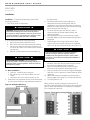
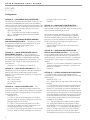
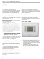
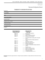
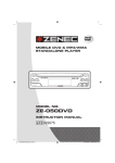
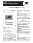
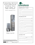
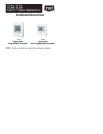
Table of Contents ATA11U03 Safety Considerations 3 General3 Package Contents 3 Installation Considerations 3 Power3 Wiring3 Thermostat Location 3 Installation4 Configuration Non-Programmable Heat Pump Thermostat 5-8 Entering and Exiting Configuration Mode 5 Configuration Options 5 Exiting Configuration Mode 8 System Start-Up and Checkout 8 Installer Test Mode 8 Terminating Installer Test 8 Checklist 8 Operation 9 Mode Selection 9 Fan Selection 9 Fan Display 9 Set Temperature Selection 9 Display Lighting 9 Remote Sensor Temperature Display 9 Timers10 Installation Manual 97B0082N06 Revised: 16 September, 2013 FOR INSTALLER AND OWNER ONLY Five-Minute Compressor Timeguard 10 Minimum On Timer 10 Cycle Timer 10 Troubleshooting 10 Space Temperature Sensor Failure 10 Memory Failure 10 Equipment Outputs 10 Wiring Diagrams 10 Thermostat Configuration Record 11 Revision History 12 WATER-SOURCE HEAT PUMPS ATA11U03 R e v. : 0 9 / 1 6 / 1 3 This Page Intentionally Left Blank 2 THE SMART SOLUTION FOR ENERGY EFFICIENCY ATA11U03 R e v. : 0 9 / 1 6 / 1 3 General Safety Considerations Read and follow manufacturer instructions carefully. Follow all local electrical codes during installation. All wiring must conform to local and national electrical codes. Improper wiring or installation may damage thermostat. This Installation Instruction covers installation, configuration, and startup of the non-programmable heat pump thermostat. This manual is intended for installer and owner only. Package Contents Recognize safety information. This is the safety alert symbol . When the safety alert symbol is present on equipment or in the instruction manual, be alert to the potential for personal injury. 1 - Thermostat 1 - Backplate (mounting base with terminal strips) 2 - Screws and anchors 3 - User Operating Manual (review with end user) Understand the signal words DANGER, WARNING, and CAUTION. These words are used with the safety alert symbol. DANGER identifies the most serious hazards which will result in severe personal injury or death. WARNING signifies a hazard which could result in personal injury or death. CAUTION is used to identify unsafe practices which would result in minor personal injury or property damage. Installation Considerations General Non-programmable heat pump thermostats are wallmounted, low-voltage thermostats that maintain room temperature by controlling the operation of heat pump systems. A variety of features are provided including separate heating and cooling set points, auto changeover, keypad lockout, backlighting, and built-in installer test. Figure 1: Non-Programmable Heat Pump Thermostat Power - 24 volt AC (50/60 Hz) power via the Rc/Rh and C terminals. Rc and Rh terminals are connected via factoryinstalled jumper wire. Wiring - Requires 6 conductor thermostat cable for 2 fan speed units. The wire length should be no more than 250 ft (76 m). Use 22 AWG (American Wire Gage) for normal wiring applications. Continuous wire lengths over 100 ft (30.5 m) should use 20 AWG or larger. Reconfigure if unit is only 1 fan speed, see option 40. Note: This thermostat has battery compartment but is non-operational and must be wired. Thermostat Location — The thermostat should be mounted: • approximately 5 ft (1.5 m) from the floor • in the conditioned space, preferably on an inside wall on a section of wall without pipes or ductwork The thermostat should NOT be mounted: • close to a window, on an outside wall, or next to a door leading to the outside • where exposed to direct light and heat or any other temperature-radiating object which may cause a false reading • close to or in direct airflow from supply registers or return air grille in areas with poor air circulation. 3 WATER-SOURCE HEAT PUMPS ATA11U03 R e v. : 0 9 / 1 6 / 1 3 Installation Installation - To install the thermostat, perform the following procedure: 1. Turn off all power to equipment. � WARNING! � WARNING! Electrical shock can cause personal injury and death. Before installing thermostat, shut off all power to this equipment during installation. There may be more than one power disconnect. Tag all disconnect locations to alert others not to restore power until work is completed. 2. If an existing thermostat is being replaced: a. Remove existing thermostat from wall. b. Record the wire color and old terminal marking. c. Disconnect wires from existing thermostat, one at a time. Be careful not to allow wires to fall back into the wall. d. Recycle old thermostats that contain Mercury. � CAUTION! � ENVIRONMENTAL HAZARD! Failure to follow this caution may result in environmental damage. Mercury is a hazardous waste. Federal regulations require that mercury be disposed of properly. the thermostat. 4. Pull thermostat wires through large hole in backplate. Level back-plate against wall (for appearance only, the thermostat does not need be leveled for proper operation) and mark wall through two mounting holes. See Fig. 2. 5. For direct mounting to wall, drill two 3/16-in. mounting holes in the wall where marked, use anchors provided. 6. Secure backplate to box or wall with two screws provided. Make sure all wires extend through hole in backplate. 7. Adjust length and routing of each wire to reach proper connector block and terminal on backplate with 1/4-in. (6 mm) of extra wire. Strip only 1/4-in. of � CAUTION! � Failure to follow this caution may result in equipment damage or improper operation. Improper wiring or installation may damage the thermostat. Check to make sure wiring is correct before proceeding with installation or turning on unit. 8. insulation from each wire to prevent adjacent wires from shorting together when connected. Match and connect equipment wires to proper terminals of the connector blocks (see Fig. 3). Push any excess wire into wall and against backplate. Seal hole in wall to prevent air leaks. Leaks can affect operation. Attach thermostat to backplate by inserting tab on bottom edge and hinging up until top snap secures. Turn ON power to unit. 2.A New Installation - a. Optional - install 2x4 box horizontal. b. Run new wiring, must meet all NEC and local codes. c. Note each wire color and connection at unit. 3. Press the thumb release at the top of the thermostat and pull apart carefully to separate back-plate from 9. Figure 2: Backplate Mounting When power is applied, all display icons are lit for 2 seconds to test the display. Following this, the equipment type for which the thermostat is configured is displayed for an additional 2 seconds. 10. 11. Figure 3: Terminal Strip (wiring diagram - see figure 7) 4 THE SMART SOLUTION FOR ENERGY EFFICIENCY ATA11U03 R e v. : 0 9 / 1 6 / 1 3 Configuration Configuration Configuration options enable the installer to configure the thermostat for a particular installation. These configuration options are stored to the internal memory so they are retained through a power outage. The availability of some configuration options will be dependent upon other conditions in the thermostat. � NOTICE � Wall thermostat requires configurating for on board sensing. Installer must configure 05 to L unless remote sensor is used. WARNING! User should not reconfigure installer set up. Equipment damage could occur. Table 1: Configuration Options Summary Configuration All changes to the installer configuration are saved as they are made. There is no provision to exit the installer configuration and cancel the change. The installer will have to manually change a configuration back to its original value to “undo” a change. Configuration Options � WARNING! � Option Number to select a new value. The mode button can be used to toggle/move the selection between the configuration option number and the configuration value. To exit the installer configuration screen, press the fan button. If no button is pressed for three minutes, the installer configuration screen will time out and the thermostat will return to normal operation. Default 02 Remote Sensor Selection rS 03 English/Metric F 05 Space Temperature Sensing r 07 Equipment DDC Controller 11 Deadband between Heating and Cooling Set Points 5 13 Space Temperature Display Adjustment (Offset) 0 15 Auto Mode Availability 16 Maximum Cycles Per Hour 18 Backlight Configuration 20 Outdoor Air Temperature Adjustment (Offset) 21 Keypad Lockout OF 26 Minimum Cooling Set Point 60 27 Maximum Heating Set Point 85 39 Temperature Display St 40 Fan Speeds Selection 2 OF ON 4 OF 0 Entering and Exiting Configuration Mode - Press and hold the fan button for about 10 seconds. After the 10 second period the Option number “02” will appear flashing in the space temperature location. The value of the configuration setting will be displayed in the set point location. The parameter that is changeable will be determined by the flashing area. The up or down buttons can be used OPTION 02 — REMOTE SENSOR SELECTION — A remote sensor 17B0008N05 (for inside duet), or ASW06 (for wall) can be connected to the S1 and S2 screw terminals to sense either remote space, return air, outdoor air, or supply air temperature. Selection: rA, Od, SA, rS rA* — Sense return air temperature * Display only, not used for temperature control. Od*— Sense outdoor air temperature SA*— Sense supply air temperature rS — Sense remote space temperature Default: rS Note: Option 02 cannot be changed from the rS setting if Option 05 is set to either r or Lr. OPTION 03 — ENGLISH/METRIC — This configuration selects be-tween Fahrenheit (F) and Celsius (C) operation. Selection: F, C Default: F OPTION 05 — SPACE TEMPERATURE SENSING — This selection determines which sensor the control will use for measuring space temperature. Space temperature can be sensed in one of three ways: the local sensor (L) located on the thermostat, the remote sensor (r), or the average of local and remote sensors (Lr). Selection: L, r, Lr (Do not use) L — Local sensor: The onboard thermistor is the control point for the temperature control algorithm. r — Remote space sensor: The remote space temperature is the control point for the temperature control algorithm. NOTE: This selection is only available if Option 02 indicates that the S1, S2 terminals are sensing a remote space temperature. Default: r 5 WATER-SOURCE HEAT PUMPS ATA11U03 R e v. : 0 9 / 1 6 / 1 3 Configuration OPTION 07 — EQUIPMENT DDC CONTROLLER — This selection should be set to ON when control is to be used with ClimateMaster heat pump units, the DXM or CXM will take care of the timeguard and cycle timers. The minimum on time is still controlled by the thermostat. Off setting could delay compressor start by 12 minutes. Selection: OF(F), ON OF — Timeguard and cycle timers are enabled ON — Timeguard and cycle timers are disabled Default: OF (off) OPTION 11 — DEADBAND BETWEEN HEATING AND COOLING SET POINTS — This selection allows the installer to choose how much differential will exist between the heating and cooling set points. Selection: 1 to 10 (F or C) Default: 5 OPTION 13 — SPACE TEMPERATURE DISPLAY ADJUSTMENT (OFFSET) — This configuration is the number of degrees to be added to the displayed temperature to calibrate or deliberately miscalibrate the measured space temperature. This selection is not available to the installer if Option 39 is set to SP (set point display). Selection: –5 to 5 F (always in F) Default: 0 OPTION 15 — AUTO MODE AVAILABILITY — The ON selection will allow automatic changeover between heating and cooling as demand requires a mode selection. OF maintains either heating or cooling mode selection only. Selection: ON, OF(F) ON — Auto mode OF — Manual mode Default: ON OPTION 16 — MAX CYCLES PER HOUR — The maximum cycle rate is limited by internal timers to the selected number of cycles per hour. Selection of a higher number causes faster cycling resulting in more constant room temperature. Selection: 4, 6, 8 4 — The Y1 output will be energized at most twice per hour. When an output is energized, it will not be energized again for 15 minutes. 6 — The Y1 output will be energized at most four times per hour. When an output is energized, it will not be energized again for 10 minutes. 8 — The Y1 output will be energized at most six times per hour. When an output is energized, it will not be 6 energized again for 8 minutes. Default: 4 OPTION 18 — BACKLIGHT CONFIGURATION — When set to OF (off), the backlight will be lit for 10 seconds after a button is pressed. After 10 seconds of no button presses, the backlight turns off. When ON is enabled, the backlight will normally be on and dim in appearance. The backlight brightness becomes brighter when a button is pressed. After 10 seconds of no button presses, the backlight will return to the dimmer level until another button press occurs. Selection: OF(F), ON Default: ON with 24 vac power; for batteries only, default is OFF. OPTION 20 — OUTDOOR AIR TEMPERATURE DISPLAY ADJUSTMENT (OFFSET) — This selection is not available unless Option 02 is set to Od (outdoor air temperature) and a valid sensor is connected to S1 and S2 terminals. It allows the calibration, or deliberate mis-calibration of the outdoor air temperature sensor reading. Selection: –5 to 5 (number of degrees F added to the outdoor air temperature reading to “calibrate” the temperature sensor) Default: 0 OPTION 21 — KEYPAD LOCKOUT WITH PASSCODE — The thermostat is shipped with the keypad fully accessible. This option allows the installer to limit access to the keypad. Selection: OF(F), 1, cd OF — When set to OF, the user has full access to the keypad 1 — The user will only have access to modify the set points (within the set point limits of Option 26 and Option 27). The padlock icon will be displayed until the user presses and holds the up and down buttons simultaneously for five seconds to unlock the keypad. Once the keypad is unlocked, the user has full access to the thermostat functionality. The keypad returns to the locked condition after no buttons have been pressed for two minutes. cd — The entire keypad is locked and the padlock icon is displayed. When the user presses a button the backlight turns on to maximum brightness for 10 seconds and a “--” is displayed in the temperature setting. The user must enter the unlock code and press the mode button to unlock the thermostat. The padlock icon will then turn off and the user will THE SMART SOLUTION FOR ENERGY EFFICIENCY ATA11U03 R e v. : 0 9 / 1 6 / 1 3 Configuration have full access to the thermostat functionality. The thermostat will lock after no buttons have been pressed for two minutes. If the option value is set to “cd”, the mode, up and down buttons will work as follows: 1. Pressing the mode button once will display the flashing Option number (21). 2. Pressing the mode button again and the option value will flash OF, 1 or cd. 3. Pressing the mode button a third time will display the keypad lock icon and the code entry values (see Fig. 4). The up and down buttons will allow the selection of a code value between 00 to 199. 4. Pressing the mode key again will return the focus to the Option number (21) . type allows both heating and cooling operations, so the minimum is 50 F plus Option 11 (deadband) and the maximum is 90 F. Selection: minimum = 50 F, maximum = 90 F – deadband Default: 85 F (based on adjustable deadband default = 5) OPTION 39 — TEMPERATURE DISPLAY — This configuration allows the installer to select either the set point temperature or the space temperature to be displayed on the large temperature display digits. When the option St is chosen, the space temperature, as defined by Option 05, is displayed using the traditional space temperature digits on the LCD display. The current set temperature is displayed using the normal set-point display digits. Default: OF (off) OPTION 26 — MINIMUM COOLING SET POINT — This parameter establishes the minimum cooling set point that the user is allowed to set. Otherwise, the equipment type allows both heating and cooling operation, so the minimum is 60 F plus Option 11 (deadband) and the maximum is 90 F. Selection: minimum = 60 F + deadband, maximum = 90 F Default: 60 F (based on the adjustable deadband default = 5) OPTION 27 — MAXIMUM HEATING SET POINT — This parameter establishes the maximum heating set point that the user is allowed to set. The equipment Figure 4: Selection of Code Value When SP is chosen, the current set point temperature is displayed using the traditional space temperature digits on the LCD display. The normal set point display digits remain blank. Space temperature is not be displayed, but if a problem occurs with the actual space temperature sensor, the characters “- -” will be displayed instead of the set temperature to indicate that the temperature sensor has an error. NOTE: The “Actual Temp” icon is not to be displayed when the sensor type is set to Set Point display (SP). Selection: St, SP Default: St (Space Temperature) OPTION 40 — FAN SPEEDS — This configuration allows the installer to select the number of fan speeds the system with operate with. When set to 1, the single speed fan only will be available (LO). When set to 2, both fan speeds will be available (LO & HI). Selection: 1, 2 Default: 2 Check unit submittal for fan speeds available. Set accordingly. OPTION 99 — RESET TO FACTORY DEFAULTS — This configuration allows the installer to return the thermostat to its “out of the box” settings. Not recommended to use. IMPORTANT: All configuration settings, mode, fan and set point settings which have been manually entered will be lost and will require resetting. When this setting is first selected, 99 will be displayed in the space temperature location and an initial value of 10 7 WATER-SOURCE HEAT PUMPS ATA11U03 R e v. : 0 9 / 1 6 / 1 3 will be displayed in the set-point location. To initiate factory defaults, the installer then presses the mode button until the 10 is flashing. The installer then presses and holds the down button. While the down button is held, the 10 will count down from 10 to zero at a rate of 2 counts per second (5 seconds total). When the value reaches zero, all display segments are turned on for five seconds and the factory defaults are restored. If at any time during the countdown the installer releases the down button, the countdown terminates and the display returns to the starting value of 10. Exiting Configuration Mode - To exit the configuration mode, press the fan button. Pressing the fan button alternates the fan selection between fan auto and fan on and the fan output follows accordingly. There is no timer associated with the installer testing of the fan operation. Terminating Installer Test — After 15 minutes of no button presses by the installer, installer test is terminated. Pressing the up button, down button, or cycling thermostat power at any time during installer test terminates the installer test and returns the thermostat to normal operation. Figure 5: Installer Test Mode SYSTEM START-UP AND CHECKOUT Installer Test Mode — This thermostat has a builtin installer test capability. It allows easy operation of equipment without delays or set point adjustments to force heating or cooling. To enter installer test mode, press and hold the fan button for 15 seconds (after 10 seconds installer configuration is entered; a continuous 15 seconds and installer test is entered). At the start of installer test, the mode is Off, the fan is “fan auto” and the set point display displays “InS.” NOTE: Unit must be powered up and CXM/DXM in test mode to disable unit timers or compressor not energized for more than 5 minutes. The mode button is used to change the system operating mode to test the heating and cooling equipment. Auto mode is not available during installer test. When the mode is set to heat, “H” is displayed, heating is energized for 180 seconds. During the installer test operation, the “on” icon is displayed. At the end of the equipment test cycle the mode returns to OFF. The LCD display counts down the time remaining (in seconds, from 180 to 0) for each stage when the equipment is energized. See Fig. 5. The same procedure is repeated for the cool mode. “C” is displayed when cooling is active. The test of a heating or cooling cycle can be terminated before the timer counts down to zero by pressing the mode button. 8 Checklist — The following installer checklist should be performed after completing installation: 1. Run equipment through several heating and cooling cycles to ensure proper operation. To operate the thermostat in its normal operating mode, consult the User Operating Manual. 2. If the equipment is to be left in operation, the set points and operating mode must be properly selected. 3. Put away tools and instruments and clean up debris. 4. Review and leave this manual and User Operating Manual with owner. THE SMART SOLUTION FOR ENERGY EFFICIENCY ATA11U03 R e v. : 0 9 / 1 6 / 1 3 OPERATION Mode Selection — The mode button allows the user to display the off, heat, cool, auto icons. Pressing the mode button cycles through the available modes based on the equipment selection from Option 15. Available choices are listed in Table 2. Table 2: Mode Selection OPTION 15 AVAILABLE MODES On Off, Heat Cool, Auto Off Off, Heat, Cool Fan Selection — The thermostat offers two continuous (ON) or two cycling (AUTO) and two fan speeds high (HI) or low (LO). Pressing the fan button cycles through the following displays fan on LO, fan on HI, auto fan LO, auto fan HI. Fan Display — If Option 39 is set to display set point (SP), then the two-speed fan setting remains on the display. If the current fan speed is not shown on the display, the first press of the fan button will display the current selection. The fan selection can only be changed by a fan button press when the current selection is shown on the display. See Fig. 6. If Option 39 is set to display the space temperature (St), then the two-speed fan setting (LO or HI) remains on the display for three seconds after the last press of the fan button. Figure 6: Current Fan Selection Display Set Temperature Selection — If auto mode is not active and off mode is not active, pressing the up or down button causes the set point corresponding to the current system mode to be updated. If the up or down button is held, the set point value will be scrolled. The set point change also takes into account that Option 11 (deadband) is preserved along with ensuring that Option 26 (minimum cooling set point) and Option 27 (maximum heating set point) are taken into account to enforce set point limits. If auto mode is active, pressing the up or down button causes the set point corresponding to the current operating mode to be updated. To move between the heat and cool set points, press the mode button to toggle between set points. Once the desired set point has been adjusted, press the mode button to return to auto mode. If off mode is active, the up and down buttons are ignored for changing set point(s). When changing the set points, the following restrictions are in place. The cool set point cannot be increased above 90 degrees F (32 C) or decreased below Option 26, the minimum cooling set point. The heat set point cannot be decreased below 50 F (10 C) or increased above Option 27, the maximum heating set point. When Option 39 is set to SP (set point), the set point adjustment is displayed in the large space temperature digits. Display Lighting — The display has two levels of lighting, high level and low level. High level lighting comes on for 10 seconds when buttons are being pressed. The low level can be selected (see Option 18) for continuous backlight. Remote Sensor Temperature Display — Pressing the up and down buttons simultaneously displays the temperature of the sensor connected to the S1 and S2 terminals for five seconds, then the thermostat returns to normal operation. If the sensor is invalid, then the display shows “--” in the large temperature display digits. 9 WATER-SOURCE HEAT PUMPS ATA11U03 R e v. : 0 9 / 1 6 / 1 3 Timers — There are several timers which influence the thermostat’s operation that are listed below. If any of the timers is preventing the equipment from turning on, the “on” icon will flash. Five-Minute Compressor Timeguard — This timer prevents the Y1 output from turning on unless it has been off for 5 minutes. (Option 07 set to OF) After a power cycle, a randomized delay will be added to end of the timeguard timer to prevent multiple units from hitting the power grid all at the same time. The randomization timer will be between zero and five minutes. If a demand exists, compressor outputs will energize between 5 and 10 minutes after the power cycle. It can be defeated by simultaneously pressing the fan and up keys. Minimum On Timer — Once the equipment has been turned on, it must remain on for 3 minutes. A change in mode or set point will cancel this timer. Cycle Timer — The number of equipment cycles per hour is determined by configuration Option 16. Based on the selection of 4, 6 or 8 cycles per hour, this timer is set to 15, 10 or 8 minutes. This much time must elapse from the start of one cycle before another cycle can start, imposing the cycles per hour limits. It can be defeated for one cycle by simultaneously pressing the fan and up keys. TROUBLESHOOTING There are three system error messages that may appear on the thermostat screen indicating a problem with the thermostat’s operation. See text below for possible system error messages and their meaning. Space Temperature Sensor Failure — If the room temperature sensor fails, the temperature display will show “--” (two dashes). If the space temperature is the average of both the local and remote sensors (as configured in Option 5), and one of the sensors fails, the thermostat provides control to the valid sensor only. The display will alternate every 10 seconds between “--” for the invalid sensor and the reading from the valid sensor. Memory Failure — If there is an internal memory failure, the temperature display will show “E4,” the thermostat needs to be replaced. 10 WIRING DIAGRAMS System wiring diagram is shown for typical ClimateMaster heat pump unit. See Fig. 7. Figure 7: Typical Wiring Diagram - Heat Pump HEAT PUMP HEAT PUMP CXM/DXM THERMOSTAT Rc R Rh W W OR W1 C C G G2 S2 S1 G NOTE 1 H (DXM ONLY) REMOTE SENSOR NOTE 2 (Optional) O Y1 O is Energized for cooling G is low speed fan G2 is hi speed fan O Y or Y1 THE SMART SOLUTION FOR ENERGY EFFICIENCY ATA11U03 R e v. : 0 9 / 1 6 / 1 3 Thermostat Configuration Record THERMOSTAT CONFIGURATION RECORD INSTALLER: PART NUMBER: DATE: HOLE IN WALL SEALED: MODE SETTINGS: MODE (Off, Heat, Cool, Auto): HEATING SET POINT: COOLING SET POINT: Manufacturer reserves the right to discontinue, or change at any time, specifications or designs without notice and without incurring obligations. CONFIGURATIONDESCRIPTION USER OPTIONS SETTING Option 02 _____ Option 03 _____ Option 05 _____ Option 07 _____ _____ Option 11 _____ Option 13 Option 15 _____ Option 16 _____ Option 18 _____ _____ Option 20 Option 21 _____ Option 26 _____ Option 27 _____ Option 39 _____ Option 40 _____ Remote Sensor Selection English/Metric Space Temperature Sensing Equipment DDC Controller Deadband between Heating and Cooling Set Points Space Temperature Display Adjustment (Offset) Auto Mode Availability Maximum Cycles Per Hour Backlight Configuration Outdoor Air Temperature Display Adjustment (Offset) Keypad Lockout Minimum Cooling Set Point Maximum Heating Set Point Temperature Display Fan Speeds Available (1 or 2) Manufacturer reserves the right to discontinue, or change at any time, specifications or designs without notice and without incurring obligations. 11 WATER-SOURCE HEAT PUMPS ATA11U03 R e v. : 0 9 / 1 6 / 1 3 Revision History Date: Item: 09/16/13 Warning and Table, page 5 08/27/13 First Published Action: Updated *97B0082N06* 97B0082N06 We work continually to improve our products. As a result, the design and specifications of each product at the time of order may be changed without notice and may not be as described herein. Please contact our Customer Service Department at 1-405-745-6000 for specific information on the current design and specifications. Statements and other information contained herein are not express warranties and do not form the basis of any bargain between the parties, but are merely our opinion or commendation of its products. We are a proud supporter of the Geothermal Exchange Organization - GEO. For more information visit geoexchange.org 12 © LSB, Inc. 2013 Rev.: 16 September, 2013