1
Direct Connection Rearview Camera
HCE-C117D
• OWNER'S MANUAL
Please read before using this equipment.
• MODE D,EMPLOI
Veuillez lire avant d,utiliser cet appareil.
• MANUAL DE OPERACION
Lealo antes de utilizar este equipo.
ALPINE ELECTRONICS MARKETING, INC.
1-1-8 Nishi Gotanda,
Shinagawa-ku,
Tokyo 141-0031, Japan
Phone 03-5496-8231
ALPINE ELECTRONICS OF AMERICA, INC.
19145 Gramercy Place, Torrance,
California 90501, U.S.A.
Phone 1-800-ALPINE-1 (1-800-257-4631)
ALPINE ELECTRONICS OF CANADA, INC.
777 Supertest Road, Toronto,
Ontario M3J 2M9, Canada
Phone 1-800-ALPINE-1 (1-800-257-4631)
YAMAGATA Co., Ltd.
2-6-34, Takashima, Nishi-ku, Yokohama-shi,
Kanagawa, 220-8515 Japan
ALPINE ELECTRONICS OF AUSTRALIA PTY. LTD.
161-165 Princes Highway, Hallam
Victoria 3803, Australia
Phone 03-8787-1200
ALPINE ITALIA S.p.A.
Vi ale C. Colombo 8, 20090 Trezza no
Sui Naviglio (MI), Italy
Phone 02-484781
ALPINE ELECTRONICS GmbH
Frankfurter Ring 117, 80807 Munchen, Germany
Phone 089-32 42 640
ALPINE ELECTRONICS DE ESPANA, S.A.
Portal de Gamarra 36, Pabell6n, 32
01013 Vitoria (Aiava)-APDO 133, Spain
Phone 945-283588
ALPINE ELECTRONICS OF U.K. LTD.
Alpine House
Fletchamstead Highway, Coventry CV4 9TW, U.K.
Phone 0870-33 33 763
ALPINE ELECTRONICS FRANCE S.A.R.L.
(RCS PONTOISE B 338 101 280)
98, Rue de Ia Belle Etoile, Z.l. Paris Nord II,
B.P. 50016,95945 Roissy Charles de Gaulle
Cedex, France
Phone 01-48638989
ALPINE ELECTRONICS (BENELUX) GmbH
Leuvensesteenweg 51 O-B6,
1930 Zaventem, Belgium
Phone 02-725-13 15
Designed by ALPINE Japan
Printed in Japan (Y)
68-13530Z84-A
Operating Instructions
English
it wARNING
This symbol means important
instructions. Failure to heed them can
result in serious injury or death.
WHEN USING A CAMERA SYSTEM, THE DRIVER MUST
VISUALLY CHECK ACTUAL CONDITIONS AROUND
THE VEHICLE. MAKE SURE THERE ARE NO PERSONS
OR ANIMALS IN THE AREA IN WHICH YOU ARE
MANEUVERING OTHERWISE YOU COULD INJURE
THEM.
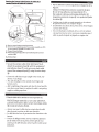
A camera assists the driver by sending images to the screen
showing conditions in view of the camera. The camera
uses a wide-angle lens, therefore, there is a difference in
distance perspective between what is normally seen and
what appears on the screen. Also, the images shown by the
rearview camera are reversed, so as to appear the same as
what is seen through the rearview mirror.
The camera may not perform to full capability due to
variables such as:
•
•
•
•
•
•
•
•
•
•
•
weather conditions such as hard rain, snow, fog or mud
extremely high or low temperatures near camera
slope of vehicle and/ or roadway
direct exposure to very bright light such as headlamp or bright
sunlight
moving from very dark to very bright light and vice versa such
as in parking garages or tunnels
extremely low light areas
walls or objects that are located diagonally in relation to the
camera
retracted mirrors that change camera viewing angle
open doors or trunks
changes to height of vehicle due to loading capacity or hydraulic
suspensions
obstacles located at the corner of the vehicle
DO NOT DISASSEMBLE OR ALTER.
Doing so may result in an accident, fire or electric shock.
KEEP SMALL OBJECTS SUCH AS BOLTS OR SCREWS
OUT OF THE REACH OF CHILDREN.
Swallowing them may result in serious injury. If swallowed,
consult a physician immediately.
USE THE CORRECT AMPERE RATING WHEN
REPLACING FUSES.
Failure to do so may result in fire or electric shock.
USE ONLY IN CARS WITH A 12 VOLT NEGATIVE
GROUND.
(Check with your dealer if you are not sure.) Failure to do
so may result in fire, etc.
BEFORE WIRING, DISCONNECT THE CABLE FROM THE
NEGATIVE BATTERY TERMINAL.
Failure to do so may result in electric shock or injury due
to electrical shorts.
DO NOT USE BOLTS OR NUTS IN THE BRAKE
OR STEERING SYSTEMS TO MAKE GROUND
CONNECTIONS.
Bolts or nuts used for the brake or steering systems (or any
other safety-related system), or tanks should NEVER be
used for installations or ground connections. Using such
parts could disable control of the vehicle and cause fire etc.
DO NOT DAMAGE PIPE OR WIRING WHEN DRILLING
HOLES.
When drilling holes in the chassis for installation, take
precautions so as not to contact, damage or obstruct pipes,
fuel lines, tanks or electrical wiring. Failure to take such
precautions may result in fire.
MINIMIZE DISPLAY VIEWING WHILE DRIVING.
Viewing the display may distract the driver from looking
ahead of the vehicle and cause an accident.
DO NOT SPLICE INTO ELECTRICAL CABLES.
Never cut away cable insulation to supply power to other
equipment. Doing so will exceed the current carrying
capacity of the wire and result in fire or electric shock.
DO NOT INSTALL IN LOCATIONS WHICH MIGHT
HINDER VEHICLE OPERATION, SUCH AS THE
STEERING WHEEL OR GEARSHIFT.
Doing so may obstruct forward vision or hamper
movement etc. and results in serious accident.
DO NOT ALLOW CABLES TO BECOME ENTANGLED IN
SURROUNDING OBJECTS.
Arrange wiring and cables in compliance with the manual
to prevent obstructions when driving. Cables or wiring that
obstruct or hang up on places such as the steering wheel,
gear lever, brake pedals, etc. can be extremely hazardous.
DO NOT ROUTE ELECTRICAL CABLES NEAR HOT OR
MOVING PARTS
Route the cables and wiring away from hot or moving
parts, and fix them securely to avoid heat/mechanical
damage to the cable insulation, which may result in
shortcircuit, fire or electric shock.
MAKE THE CORRECT CONNECTIONS.
When making connections to the vehicle's electrical
system, be aware of the factory installed components (e.g.
on-board computer). Do not tap into these leads to provide
power for this unit. When connecting the device to the
fuse box, make sure the fuse for the intended circuit of
the device has the appropriate amperage. Failure to do so
may result in fire or damage to the unit and/ or the vehicle.
When in doubt, consult your Alpine dealer.
USE THIS PRODUCT FOR MOBILE 12 VOLT
APPLICATIONS.
Use for other than its designed application may result in
fire, electric shock or other injury.
CHECK THAT THE CAMERA MOUNTINGS IS ATTACHED
SECURELY, AND THAT THE SCREWS ARE TIGHT
BEFORE DRIVING.
Failure to do so may result in an accident.
WHEN INSTALLING OR CHECKING A CAMERA, DO SO
AFTER PARKING THE CAR IN A LEVEL, SAFE PLACE,
TURNING OFF THE ENGINE, AND APPLYING THE
HAND BRAKE.
Failure to do so may result in an accident.
WHEN USING A DRILL TO MAKE A HOLE, TAKE
PRECAUTIONS SUCH AS WEARING GOGGLES SO
FRAGMENTS DO NOT GET INTO THE EYES.
Failure to do so may result in injury.
~CAUTION
This symbol means important
instructions. Failure to heed them can
result in injury or material property
damage.
HAVE THE WIRING AND INSTALLATION DONE BY
EXPERTS.
The wiring and installation of this unit requires special
technical skill and experience. To ensure safety, always
contact the dealer where you purchased this product to
have the work done.
ARRANGE THE WIRING SO IT IS NOT CRIMPED OR
PINCHED BY A SHARP METAL EDGE.
Route the cables and wiring away from moving parts (like
the seat rails) or sharp or pointed edges. This will prevent
crimping and damage to the wiring.
USE SPECIFIED ACCESSORY PARTS AND INSTALL
THEM SECURELY.
Be sure to use only the specified accessory parts. Use
of other than designated parts may damage this unit
internally or may not securely install the unit in place. This
may cause parts to become loose resulting in hazards or
product failure.
CONNECT LEADS PROPERLY
Be sure to connect the color coded leads according to
the diagram. Incorrect connections may cause the unit
to malfunction or cause damage to the vehicle's electrical
system.
HALT USE IMMEDIATELY IF A PROBLEM APPEARS.
Failure to do so may cause personal injury or damage to
the product. Return it to your authorized Alpine dealer or
the nearest Alpine Service Center for repairing.
EXCEPT FOR THE CAMERA, DO NOT ATTACH ANY
PARTS TO AREAS WHICH WILL GET WET, OR WHERE
THERE IS A LOT OF HUMIDITY OR DUST.
Failure to do so may result in fire or damage.
DO NOT ATTACH THE CAMERA MOUNTING TO
FLUOROCARBON RESIN FINISHED CAR BODIES OR
GLASS.
Doing so could cause the strength of the camera mounting
to weaken, which could cause it to fall of and cause
accidents, injury, or damage to the car body.
DO NOT ATTACH THE CAMERA MOUNTING TO ANY
SURFACE WHERE THE ENTIRE ADHESIVE SURFACE
CANNOT BE APPLIED.
Doing so could cause the strength of the camera mounting
to weaken, which could cause it to fall of and cause
accidents, injury, or damage to the car body.
NOTICE
• About Care of Device
Do not assert any excess pressure to the camera or the
mounting, as this could cause the camera direction to shift, or
the camera mounting bracket to come off.
• To prevent the camera lens, mounting and cords from changing
color or shape, or from deteriorating, wipe with a chemical-free,
damp cloth.
• When washing the car, do not using an automatic car washer, or
high-pressure washer. Doing so could cause the camera to come
off, damage to the device cord, or may allow water to enter the
camera or the inside of the car.
• In some cases, to attach the device, a hole must be drilled in the
car body, requiring use of touch-up paint (retail product) for
rust-prevention, and should be prepared beforehand.
• Be sure to disconnect the cable from the (-) battery post before
installing your HCE-Cll7D. This will reduce any chance of
damage to the unit in case of a short -circuit.
• Be sure to connect the color coded leads according to the
diagram. Incorrect connections may cause the unit to
malfunction or damage to the vehicle's electrical system.
• When making connections to the vehicle's electrical system,
be aware of the factory installed components (e.g. on-board
computer). Do not tap into these leads to provide power for this
unit. When connecting the HCE-Cll7D to the fuse box, make
sure the fuse for the intended circuit of the HCE-Cll7D has the
appropriate amperage. Failure to do so may result in damage to
the unit and/ or the vehicle. When in doubt, consult your Alpine
dealer.
• About Rear Camera
The rear camera of this camera system is a dedicated product.
Do not connect it to other cameras.
• About Power Connection
Connect a reverse input cable (orange/white) to the power cable
of the rear lamp. For details, consult a dealer purchased camera,
or car dealer. Connect this to a power cable of the rear lamp, but
not to the positive of the rear lamp signal cable.
• Do not use mobile phones and wireless devices near the
camera.
• Doing so may result in noise on the screen or malfunction. It is
recommended to use mobile phones or wireless devices away
from the camera.
• About Camera Installation Location
Before installing, make sure there is a enough space to be able
to install the camera. If possible, install the camera in the center
of the bumper or other fitting. If the camera is installed at a
distance left or right of center, the image may differ from the
real view.
• Confirming the Display Function
To connect the unit, confirm that the monitor will require a
compatible RCA pin jack.
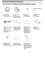
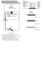
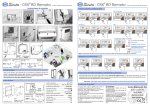
lnstallation/lnstallation/lnstalacion
x2
G) Rearview Camera
G) Camera de recul
G) Camara de marcha atras
®
®
®
Camera mounting
bracket
Support de fixation
Soporte de Ia camara
QD Hexagonalwrench
QD Cle6pans
QD Llave hexagonal
@ Hexscrew
@ Vis hexagonale
@ Tornillo hexagonal
\
I
xS
® Camera extension cable
(10.5m}
@ Rallonge cable camera
(10,5m}
® Cable de extension de Ia
camera (1 O,Sm}
® Waterproofing pad
@ Protege cable etanche
® Dispositivo protector
resistente al agua
0
0
0
Waterproofing pad
adhesive sheet
Adhesif pour protege
cable etanche
Hoja adhesiva para el
dispositivo protector
resistente al agua
x4
®Self-tapping screw
® Vis autotaraudeuse
® Tornillo macho roscador
@) Heat-shrink Tube
@) Tube thermoretractable
@) Tubo termorretractil
@ Camera mounting
bracket for KTX-C1 OLP
@ Support de fixation de Ia
camera pour KTX-C1 OLP
@ Soporte de montaje
de Ia camara para KTXC10LP
®Wire clamp
® Attache fils
® Fijador de cables
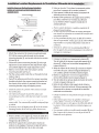
Install the Camera on the Rear Bumper{lnstallez Ia
camera sur Ia carrosserje arrji:reflnstaladOn en el
acabado trasero
3 Faites un trou de 13 mm dans Ia carrosserie arriere
pour fixer le support de Ia camera (schema 3).
4 Faites passer le cable de Ia camera al'interieur du
vehicule par le trou fait al'etape 3.
5 Retirez le film protecteur du support de Ia camera,
puis fixez ce dernier sur le chassis du vehicule.
Le cas echeant, fixez le support al'aide des vis
autotaraudeuses.
Fig.l!Schema 1/Fig.l
Fig.2/Schema 2/Fig.2
Fig.3/Schema 3/Fig.3
English
2
3
4
5
Attach the camera to the camera mounting bracket
®.Pull the camera cable through to the camera
mounting bracket@, and secure with the hex screws
@ (see Fig. 2).
Loosen the camera mounting bracket® and angle
adjustment screw. Determine the attachment angle,
and carefully tighten the angle adjustment screw.
Make a 13 mm hole in the rear bumper camera
mounting bracket (see Fig. 3).
Pull the camera cable inside the car through the hole
made in step 3.
Peel off the adhesive seal from the camera mounting
bracket and attach the camera mounting bracket on
the chassis of the vehicle. If required, fix the camera
mounting bracket using self-tapping screws.
• Attach the camera in a position where it does not touch
the number plate.
• Use retail touch-up paint to paint the surface and
surrounding area when a hole has been made in a metal
surface.
• Make sure water cannot enter the hole made for the
camera cable. Use commercially available waterproof tape
or sealant.
• If necessary, use a self-tapping screw® to fix the camera
mounting bracket (In the case of a plastic mount area).
Fran~ais
Fixez Ia camera sur le support@. Passez le cable de Ia
camera dans le support@, puis fixez-le a!'aide des vis
hexagonaux@ (schema 2).
2 Deserrez le support de Ia camera® et inserez en
angle Ia vis de reglage. Choisissez I'angle de fixation,
puis reserrez delicatement Ia vis dans cet angle.
• Fixez la camera de fa~on ace qu 'elle ne touche pas la
plaque d'immatriculation.
• Si vous avez perce un trou dans une surface metallique,
une retouche est necessaire sur et autour de la surface avec
une peinture speciale.
Le trou permettant de faire passer le cable de la camera
do it etre impermeable. Utilisez pour cela du ruban adhesif
impermeable ou un produit detancheite vendu dans le
commerce.
• Si besoin est, utilisez une vis autotaraudeuse ® pour
fixer le support de la camera (notamment si la surface de
montage est en plastique).
Espanol
2
3
4
5
Coloque Ia camara en el soporte de Ia camara ®.
Tire del cable de Ia camara a traves del soporte de Ia
camara ® y ffjelo con los tornillos hexagonales@
(vease Ia figura 2).
Afloje el soporte de Ia camara ® e inserte en angulo
el tornillo de ajuste. Calcule el angulo de fijaci6n y,
con cuidado, apriete el tornillo en dicho angulo.
Real ice un agujero de 13 mm en el soporte de Ia
camara del acabado trasero (vease Ia figura 3).
Tire del cable de Ia camara desde el interior del coche
a traves el agujero del paso 3.
Retire el sello adhesivo del soporte de Ia camara y
ffjelo en el chasis del vehfculo. Si fuera necesario, fije
el soporte de Ia camera con ayuda de los tornillos
embriados suministrados.
• Coloque la camara en una posicion en la que no toque la
matricula.
• Utilice pintura para retocar la superficie y el area que
rodea el agujero realizado en la superficie de metal.
• Es importante que no entre agua en el orificio del cable de
la camara. Utilice cinta adhesiva resistente al agua o un
sellador.
• Si es necesario, utilice un tornillo macho roscador ® para
fijar el soporte de la camara (en caso de que el area de
instalaci6n sea de plastico ).
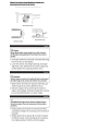
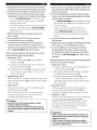
Conpectjops/Raccordemepts/Copexjopes
Espanol
• Para obtener mas informacion acerca de la conexion,
consulte el manual de instalacion del producto compatible
con el HCE-C117D. Conecte unicamente el conector de
entrada de la camara de vision trasera.
HCE-C117D-compatible Alpine AV Head Unit*/
Unite principale AV Alpine compatible avec
HCE-C117D*/
Unidad principal AV de Alpine compatible con
el HCE-C117D*
*
i
Camera extension cable (supplied)/
Rallonge cable camera (fournie)/
Cable de extensi6n de Ia camera (suministrada)
Rearview Camera/
Camera de recul/
L ~~
Camara de marcha atras
Fig.4/Schema 4/Fig.4
English
• For details on connection, refer to the installation manual
of the HCE-C117D-compatible product. Connect the rear
camera input connector only.
*
This product can only connect to Alpine Mobile Media
Stations with the dedicated Alpine camera input. For
information on HCE-C1170-compatible products,
contact your local authorized Alpine dealer or visit the
Alpine America home page (http://www.alpine-usa.
com).
Fran~ais
• Pour plus de details sur la connexion, consultez le guide
d'installation du produit compatible avec HCE-C117D.
Raccordez uniquement la borne d'entree de la camera
arriere.
*
Cet appareil ne peut etre raccorde qu'a une station
multimedia portable Alpine via Ia borne d'entree de
Ia camera Alpine. Pour plus d'informations sur les
produits compatibles avec HCE-C1170, contactez votre
revendeur Alpine ou visitez Ia page d'accueil du site Web
Alpine America (http://www.alpine-usa.com).
Este producto solo puede conectarse a equipos Mobile
Media de Alpine con una entrada exclusiva de c3mara
de Alpine. Para obtener mas informacion acerca de los
productos compatibles con el HCE-C1170, pongase en
contacto con su distribuidor Alpine autorizado o visite
Ia pagina principal de Alpine America (http://www.
alpineusa. com).
Adjustjnq the Camera Anqle/R@qlaqe de I'angle de Ia
cam@ra/Ajyste del lnqylo de Ia c;imara
II
Fig.5/Schema 5/Fig.S
Fig. 7 /Schema 7/Fig. 7
Fig.6/Schema 6/Fig.6
English
&caution
When adjusting the camera angle, do so after turning
off the engine and applying the hand brake to avoid an
accident.
Put the gear shift into reverse (R), and check the image
from the camera on the display.
2 Loosen the camera mounting bracket® and angle
adjustment screw. Determine the camera angle, and
carefully tighten the angle adjustment screw.
Fran~ais
&Attention
Veillez a COUper le moteur eta mettre le frein a main avant
de regler I'angle de Ia camera afin d'eviter tout accident.
Mettez le levier de vitesse en marche arriere (R), puis
verifiez l'image de Ia camera affichee al'ecran.
2 Deserrez le support de Ia camera® et inserez en
angle Ia vis de reglage. Choisissez l'angle de Ia camera,
puis reserrez delicatement Ia vis dans l'angle.
Espariol
& Precaucion
Cuando ajuste el lngulo de Ia clmara, apague primero
el motor y ponga el freno de mano para evitar posibles
accidentes.
Ponga Ia palanca de marchas en marcha atras (R) y
compruebe Ia imagen de Ia camara que se muestra en
Ia pantalla.
2 Afloje el soporte de Ia camara ® e inserte en angulo
el tornillo de ajuste. Calcule el angulo de Ia camara y,
con cuidado, apriete el tornillo en dicho angulo.
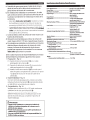
Securjna the Camera Cable/Fjxatjon du cible de Ia
camera/Fjjad6n del cable de Ia clmara
Espanol
Fije el cable de Ia camara siguiendo el diagrama de Ia
figura 8.
Coloque el dispositive protector resistente al agua
® con Ia hoja adhesiva correspondiente (J) y
fije cualquier cable que sobresalga alrededor del
dispositivo resistente al agua ® con ayuda del fijador
de cables@.
• Verifique que el cable no queda atrapado en el maletero,
las puertas traseras o en cualquier bisagra.
• El cable debe estar fuera de las protecciones de las bisagras
y arneses del vehiculo.
Una vez finalizado el cableado, abra y cierre el maletero
y las puertas traseras varias veces para compro bar que el
cable no queda atrapado ni plegado en ningun sitio.
(A) Rearview camera/Camera arriere/Camera trasera
(B) To HCE-Cll7D-compatible product/Vers le produit compatible avec HCECI17D/ AI producto compatible con el HCE-Cll7D
(C) Clam per/ Attache-fils/Fijador
(D) Waterproofing pad/Protege-cables impermeable/Dispositivo protector
resistente al agua
Fig. 8/Schema 8/Fig. 8
English
Secure the camera cable while referring to Fig. 8.
Attach the waterproof pad ® with the waterproof
pad adhesive sheet (J), and secure any slack cable
around the waterproof pad® using the wire clamp
@.
• Ensure the cable does not get caught in the trunk, rear
door(s) or any hinges.
• The cable should go on the outside of car hinges and
harness covers.
• After completing wiring, open and close the trunk and the
rear doors several times to confirm the cable is not getting
caught or rubbing anywhere.
Francrais
Fixez le cable de Ia camera en vous reportant au
schema 8.
Fixez le protege-cables® sur son ruban adhesif (J),
puis fixez et tendez le cable sortant du protege-cables
®
l'aide de !'attache-fils@.
a
• Assurez-vous que le cable n'est pas coince dans la malle,
dans les partes arrieres ou dans une charniere.
• Le cable doit etre hors des protections des charnieres et des
harnais.
• Une fois le cablage termine, ouvrez et refermez plusieurs
fois la malle arriere et les partes arrieres afin de vous
assurez que le cable n'est pas coince et qu'il ne subit aucun
frottement.
When usjnq KJX-Cl OLP (License plate Moyntjnq Kjt for
Rearyjew Cameral CSold seoaratelyl for jnstallatjon/Sj ytiliza
el modelo KTX-Cl OLP Ckjt de montaje de matricyla para
cimara traseral Cse yende por separadol para Ia jnstalad6n/
Lors de l'ytilisatjon dy kjt KTX-Cl OLP Ckjt d'jnstallatjon de
Ia plaqye d'jmmatrjcylatjon poyr Ia camera de recull Cyendu
separement) pour l'jnstallatjon
English
Install the camera on the License plate frame with the
camera bracket@ (included) and *A, B (included with
KTX-Cl OLP). (Fig.9/Fig.1 0)
• For details on how to install the camera on the License
plate frame, refer to the KTX-ClOLP Installation Manual.
~Caution
• Be sure to install the camera on the License plate frame
with its ALPINE logo up.
Fran-;:ais
J
*A
Fig.9/Schema 9/Fig.9
lnstallez Ia camera sur le cadre de Ia plaque
d'immatriculation avec le support de Ia camera@
(fourni) et *A, B (fournis avec le KTX-Cl OLP). (Fig.9/Fig.1 0)
• Pour plus de details sur !'installation de la camera sur le
cadre de la plaque d'immatriculation, consultez le guide
d'installation du KTX-ClOLP.
!
~Attention
• Veillez a installer Ia camera sur le cadre de Ia plaque
b
d'immatriculation en dirigeant le logo ALPINE vers le
haut.
r
Espanol
*A
*B
Fig.lO/Schema 10/Fig.lO
@ Camera bracket (included}/
@ Support de Ia camera (fourni}/
@ Soporte de cimara (incluido)
*A Screw with spring washer (included with KTX-Cl OLP) x4/
*A Vis avec rondelle (fourni avec le KTX-Cl OLP) x4/
*A Tornillo con arandela (incluido con el KTX-C10LP) x4
*B Base bracket (included with KTX-C1 OLP}/
*B Support de base (fourni avec le KTX-C10LP}/
*B Soporte de base (incluido con el KTX-C1 OLP)
lnstale Ia camara en el bastidor de Ia matrfcula con el
soporte de camara@ (incluido) y *A, B (incluido con el
KTX-Cl OLP). (Fig. 9/Fig. 10)
• Para obtener mas informacion sabre la instalaci6n de la
camara en el bastidor de la matricula, consulte al manual
de instalaci6n del KTX-ClOLP.
~ Precaucion
• Es muy importante instalar Ia cimara en el bastidor de
Ia matricula con ellogotipo de ALPINE hacia arriba.
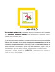
Spedallnstructjons for Pjckup Jruck lnstallatjons/
lnstryctjons spt!dales poyr jnstallatjon syr yo pjckyp/
lnstrycdones espedales para las jpstaladones ep camjopetas
t
Front of pickup truck*/
Avant du pickup* I
Parte delantera de Ia camioneta*
®Camera
extension cable/
@ Rallonge cable
@ Heat-shrink Tube/
camera/
@Tube
thermoretractable/
®Cable de
extension de Ia @Tubo
camera
termorretractil
CD Camera
CD
CD
cable/
Cable de
Camera I
Cable de
Camara
About 1 inch/
Environ 1 pouce/
Aprox. 1 pulgada
HCE-C1170-compatible Alpine AV Head Unit/
Unite principale AV Alpine compatible avec
HCE-C1170/
Unidad pricipal AV Alpine compatible con
el HCE-C1170
Fig.l2/Schema 12/Fig.l2
a
b
~ - - - - - - - - - - - - - (B)
Fig.l3/Schema 13/Fig.l3
'-
/
Fig.l4/Schema 14/Fig.l4
d
Fig.ll/Schema 11/Fig.ll
*
*
*
Any type of vehicle, including pickup trucks, where the
connector is installed outside of the cabin.!
Tout type de vehicule, notamment des camionnettes, ou le
connecteur est installe hors de la cabine.!
Cualquier tipo de vehiculo, incluidas las camionetas,
donde el conector se debe instalar fuera de la cabina.
_
English
a: Rubber grommet to pass camera wire from inside of
pickup truck cab to underside of pickup truck chassis.
b: In pickup truck* installations, the wire that connects
between the camera and the camera power supply
typically gets installed under the pickup truck chassis.
- This wire must be protected from damage using
split-loom tubing in any areas where it is installed
under the pickup chassis.
- The rubber grommet where the wire passes from the
cab to the underside of the truck must be sealed
with silicone to prevent moisture intrusion into the
pickup truck cab.
c: White connector between rearview camera and
power supply.
d: Recommended HCE-C117D rearview camera
mounting location (on rear bumper).
e: In pickup truck installations, the white electrical
connector between the rearview camera and the
camera's power supply may be exposed to moisture.
If so, it must be sealed to prevent corrosion.
Perform waterproofing with the provided heat-shrink
tube by following the procedure below:
1 Preparation -Fig.12
(1) Insert the heat-shrink tube@) over the camera
extension cable@.
(2) Connect the camera cable G) to the connector of
the camera extension cable@.
(3) Install the heat-shrink tube@) so tube (A) is entirely
covered (with an excess of approx. 1 inch) on the
camera cable G) side.
2 Waterproofing -Fig.13
When preparation is complete, straighten the cable, and
shrink the heat-shrink tube@) by heating it from side (B)
with a heat gun.
3 Check -Fig.14
Ensure that connectors (A) and (C) is entirely covered
with the heat-shrink tube@).
When the heat-shrink tube is at its smallest, epoxy
or caulk should be flowed onto the (D) sections to
complete the waterproofing process.
&caution
• Be careful not to melt the camera cable or camera
extension cable by the heat gun.
• Be careful not to burn yourself during this procedure.
• After waterproofing is complete, do not bend the cord
forcibly.
Fran~ais
a: Passe-cloison en caoutchouc pour fa ire transiter le fil
de Ia camera de l'interieur de Ia cabine du pickup vers
le dessous du chassis.
b: En cas d'installation sur un pickup*, le fil qui relie Ia
camera son alimentation est generalement installe
sous le chassis du vehicule.
- Le fil doit etre protege contre les degats au moyen
d'un tubage pour cablage, Ia ou il est installe sous le
chassis du pickup.
- Le passe -cloison en caoutchouc, utilise pour
acheminer le fil de Ia cabine vers le dessous du
pickup, doit etre protege avec du silicone pour
eviter toute intrusion d'humidite dans Ia cabine du
vehicule.
c: Connecteur blanc entre Ia camera de recul et
!'alimentation.
d: Emplacement de montage recommande de Ia camera
de recul HCE-C117D (sur le parechocs arriere).
e: En cas d'installation sur un pickup, le connecteur
electrique blanc situe entre Ia camera de recul et
son alimentation risque d'etre expose al'humidite.
Si c'est le cas, il doit etre protege afin d'eviter toute
corrosion.
a
Verifiez l'etancheite aI'aide du tube thermoretrecissable
en suivant Ia procedure ci-dessous:
1 Preparation - Fig.12
(1) lnserez le cable d'extension de Ia camera@ dans le
tube thermoretrecissable @.
(2) Raccordez le cable de Ia camera G) au connecteur
du cable d'extension de Ia camera@.
(3) lnstallez le tube thermoretrecissable@) afin que
le tube (A) soit entierement couvert (avec un
debordement d'environ 1 pouce) du cote du cable
de Ia camera G).
2 Etancheite- Fig.13
Une fois Ia preparation terminee, tendez le cable
et retrecissez le tube thermoretrecissable@) en le
chauffant du cote (B) I' aide d'un pistolet air chaud.
3 Verification - Fig.14
Verifiez que les connecteurs (A) et (C) sont entierement
couverts par le tube thermoretrecissable @.
Lorsque le tube thermoretrecissable atteint sa taille
mini male, vous devez inserer de Ia resine epoxy ou
une resine de colmatage dans les sections (D) pour
completer le processus d'etancheite.
a
Lt Attention
a
• Veillez a ne pas faire fondre le cable de Ia camera ou le
cable d'extension de Ia camera lorsque vous utilisez le
pistolet a air chaud.
• Veillez a ne pas vous bruler lors de cette procedure.
• Une fois le processus d'etancheite termine, veillez ane
pas tordre le cable de force.
Espanol
a: Arandela de goma para pasar el cable de Ia camara
desde el interior de Ia cabina de Ia camioneta a Ia
parte inferior del chasis de Ia camioneta.
b: En instalaciones realizadas en camionetas*, el cable
que conecta Ia camara y Ia fuente de alimentaci6n de
Ia camara normal mente se instala bajo el chasis de Ia
camioneta.
- Este cable debe estar protegido mediante un tuba
de hendidura en espiral en las zonas en las que se
encuentre instalado bajo el chasis de Ia camioneta.
- La arandela de goma par el que pasa el cable desde Ia
cabina hasta Ia parte inferior de Ia camioneta se debe
sellar con silicona para evitar Ia entrada de humedad
en Ia cabina de Ia camioneta.
c: Conector blanco entre Ia camara de vision trasera y Ia
fuente de alimentacion.
d: Ubicacion recomendada para colocar Ia camara de
vision trasera HCE-C117D (en el parachoques trasero).
e: En instalaciones realizadas en camionetas, el conector
electrico blanco situ ado entre Ia camara de vision
trasera y Ia fuente de alimentaci6n de Ia camara
podrfa estar expuesto a Ia humedad. En ese caso se
debe sellar para evitar Ia corrosion.
Lleve a cabo el proceso de impermeabilidad con el tubo
termorretractil suministrado siguiendo estos pasos:
1 Preparacion- Fig. 12
(1) lnserte el tuba termorretractil@) en el cable
prolongador de Ia camara @.
(2) Conecte el cable de Ia camara CD al conector del
cable prolongador de Ia camara @.
(3) lnstale el tuba termorretractil@) de modo que el
tuba (A) quede completamente cubierto (con aprox.
1 pulgada de exceso) en ellado del cable de Ia
camara G).
2 lmpermeabilidad- Fig. 13
Una vez concluida Ia preparaci6n, enderece el cable y
reduzca el tuba termorretractil@) calentandolo desde
un lado (B) con una pistola de aire caliente.
3 Comprobaci6n - Fig. 14
Verifique que el conector (A) y el (C) estan total mente
cubiertos con el tuba termorretractil @).
Cuando el tuba termorretractil este recogido,
debera introducirse epoxi o masilla para que circule
por las secciones (D) para completar el proceso de
impermeabilidad.
~ Precauci6n
• Tenga mucho cuidado de no derretir el cable de Ia
camara o el cable prolongador de Ia camara con Ia
pistola de aire caliente.
• Preste mucha atencion para no sufrir quemaduras al
realizar este procedimiento.
• Una vez concluido el proceso de impermeabilidad, no
doble el cable con fuerza.
Specifjcatjons/Splcjfjcatjons/Especifjcacjopes
English
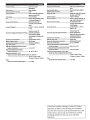
Power Requirements ............................................ 6.0V DC (5.5 to 6.5V allowable)
Ground Type .......................................................... Negative ground type
Max Power Consumption ..................................... 0.9W
Output Image ........................................................ Mirror image, VBS (NTSC Color
signal system)
Image Output ........................................................ 1 Vp-p (75 ohms)
Image Sensor ........................................................ 1/4 type color CMOS image
sensor, aspect ratio 4 : 3
Effective Number of Pixels ................................... 640 (horizontal) x 480 (vertical)
approximately 300,000 pixels
Lens Section .......................................................... Focal length: f=1.16mm,
brightness: F=2.8
Angle of field ......................................................... Horizontal: Approx 127°,
Vertical: Approx 101 o
Automatic Image Adjusting Function ................. Automatic exposure
adjustment, Automatic white
balance adjustment
Synchro-System .................................................... Internal synchronization
S/N ratio ................................................................. 40dB or more
Resolution (horizontal, center area) ................... 300 TV lines
Illumination Range ............................................... 1.5 lx or more (SO IRE or more)
Operating Temperature Range
• Camera section ............................................... -30°C to +70°C
Storage Temperature Range
• Camera section ............................................... -40°C to +85°C
External Dimensions (W x H x D)
• Camera section (except projection on the rear)
.......................................................................... 1S/16" X 15/16" X 25/32"
(23.4mm x 23.4mm x 19.3mm)
Weight
• Camera section (including cable) .................. 1 oz. (35g)
Espanol
Fran~ais
Puissance requise ................................................. 6,0 V CC (5,5 a6,5 V
admissibles)
Type de masse ....................................................... Masse negative
Puissance de sortie maxi male ............................. 0.9 W
Image reproduite .................................................. Image miroir, VBS (systeme de
signaux couleur NTSC)
Sortie image .......................................................... 1 Vp-p (75 ohms)
CCD ........................................................................ Capteur d'image CMOS couleur
1/4'~ format d'image 4 : 3
Nombre effectif de pixels ..................................... 640 (horizontal) x 480
(vertical), environ 300.000
pixels
Section de l'objectif .............................................. Focale: f = 1,16 mm, luminosite:
F=2,8
Angle de champ .................................................... Horizontal: environ 127°,
Vertical: environ 101°
Fonction de reglage automatique de I'image .... Controle automatique
de !'exposition, reglage
automatique de Ia balance des
blancs
Systeme de synchronization ................................ Synchronisation interne
Rapport signal sur bruit ....................................... 40 dB et plus
Resolution (horizontale,zone centrale) .............. 300 lines de Television
Plage d'illumination ............................................. 1,51x et plus
Plage de temperatures de fonctionnement
• Section de Ia camera ...................................... -30 a+70 oc
Plage de temperature de stockage
• Section de Ia camera ...................................... de -40 oc a+85 oc
Dimensions externes (I x H x P)
• Section de Ia camera (partie saillante arriere non comprise)
.......................................................................... 15/16" X 15/16" X 25/32"
(23.4mm x 23.4mm x 19.3mm)
Poids
• Section de Ia camera (cable compris) ........... 1 oz. (35g)
Requisitos de alimentaci6n ................................. 6,0V CC (se permite desde 5,5 a
6,5V)
Tipo de toma de tierra .......................................... Tipo toma de tierra negativa
Salida de potencia maxima .................................. 0,9 W
Imagen de salida ................................................... Imagen en espejo, VBS (sistema
de senal a color NTSC)
Salida de imagen .................................................. 1 Vp-p (75 ohmios)
Sensor de imagen ................................................. Sensor de imagen CMOS de 1/4
pulg., relaci6n de aspecto 4 : 3
Numero efectivo de pixels ................................... 510 (horizontal) x 492
(vertical), aproximadamente
250.000 pixeles
Secci6n de Ia lente ................................................ Longitud focal: f = 1,16 mm,
brillo:F=2,8
Angulo de campo .................................................. Horizontal: Aprox 127°,
Vertical: Aprox 101 o
Funci6n de ajuste de imagen automatico .......... Ajuste automatico de
exposici6n; Ajuste automatico
de balance de blancos
Sistema de sincronizaci6n ................................... Sincronizaci6n interna
Relaci6n senal-ruido............................................. 40 dB o mas
Resoluci6n (horizontal, area central) .................. 300 lineas de televisor
Alcance de Ia iluminaci6n .................................... de 1,5 a 100.000 lx
lntervalo de temperatura de funcionamiento
• Secci6n de camara .......................................... entre -30 y +70°C
lntervalo de temperatura de almacenamiento
• Secci6n de camara .......................................... entre -40 y +85°C
Dimensiones externas (ancho x alto x largo)
• Secci6n de camara (excepto proyecci6n trasera)
.......................................................................... 15/16" X 15/16" X 25/32"
(23.4mm x 23.4mm x 19.3mm)
Peso
• Secci6n de camara (incluido cable) ............... 1 oz. (35g)
This device complies with part 15 of the FCC Rules.
Operation is subject to the following two conditions.
( 1) This device may not cause harmful interference, and
(2) this device must accept any interference received,
including interference that may cause undesired
operation.
.$H/ILPINE®
LIMITED WARRANTY
ALPINE ELECTRONICS OF AMERICA, INC. AND ALPINE OF CANADA INC. ("Alpine"), are dedicated to quality craftsmanship and are pleased to offer this
Warranty. We suggest that you read it thoroughly. Should you have any questions, please contact your Dealer or contact Alpine at one of the telephone
numbers listed below.
e PRODUCTS COVERED:
e HOW WE LIMIT IMPLIED WARRANTIES:
This Warranty covers Car Audio Products and Related Accessories ("the
product"). Products purchased in the Canada are covered only in the
ANY IMPLIED WARRANTIES INCLUDING FITNESS FOR USE AND
MERCHANTABILITY ARE LIMITED IN DURATION TO THE PERIOD OF THE
Canada. Products purchased in the U.S.A. are covered only in the U.S.A.
EXPRESS WARRANTY SET FORTH ABOVE AND NO PERSON IS AUTHORIZED
TO ASSUME FOR ALPINE ANY OTHER LIABILITY IN CONNECTION WITH THE
e LENGTH OF WARRANTY:
SALE OF THE PRODUCT.
This Warranty is in effect for one year from the date of the first consumer
purchase.
e WHO IS COVERED:
This Warranty only covers the original purchaser of the product, who must
reside in the United States, Puerto Rico or Canada.
e WHAT IS COVERED:
This Warranty covers defects in materials or workmanship (parts and labor)
in the product.
e WHAT IS NOT COVERED:
This Warranty does not cover the following:
Damage occurring during shipment of the product to Alpine for repair
CD
®
(claims must be presented to the carrier).
Damage caused by accident or abuse, including burned voice coils
caused by over-driving the speaker (amplifier level is turned up and
driven into distortion or clipping). Speaker mechanical failure (e.g.
punctures, tears or rips). Cracked or damaged LCD panels. Dropped or
damaged hard drives.
@ Damage caused by negligence, misuse, improper operation or failure
@
to follow instructions contained in the Owner's manual.
Damage caused by act of God, including without limitation,
earthquake, fire, flood, storms or other acts of nature.
e HOW STATE/PROVINCIAL LAW RELATES TO THE
WARRANTY:
This Warranty gives you specific legal rights, and you may also have other
rights which vary from state to state and province to province. In addition,
some states/provinces do not allow limitations on how long an implied
warranty lasts, and some do not allow the exclusion or limitation of
incidental or consequential damages. Accordingly, limitations as to these
matters contained herein may not apply to you.
eiN CANADA ONLY:
warranty stamped upon installation by the installation center.
Any product which has the serial number defaced, altered or removed.
e HOW TO CONTACT CUSTOMER SERVICE:
Should the product require service, please call the following number for
your nearest Authorized Alpine Service Center.
Any product not distributed by Alpine within the United States, Puerto
Rico or Canada.
CAR AUDIO
1-800-ALPINE-1 (1-800-257-4631)
Any product not purchased from an Authorized Alpine Dealer.
NAVIGATION
1-888-NAV-HELP (1-888-628-4357)
e HOW TO OBTAIN WARRANTY SERVICE:
CD
REPAIRING OR REPLACING OTHER PROPERTY WHICH IS DAMAGED WHEN
THIS PRODUCT DOES NOT WORK PROPERLY. THE REMEDIES PROVIDED
UNDER THIS WARRANTY ARE EXCLUSIVE AND IN LIEU OF ALL OTHERS.
product.
Alpine's consent.
®
RENTALS OR OTHERS COSTS RELATING TO THE CARE AND CUSTODY OF THE
PRODUCT. THE TERM "CONSEQUENTIAL DAMAGES" REFERS TO THE COST OF
Any cost or expense related to the removal or reinstallation of the
(j) Any product which has been adjusted, altered or modified without
@
ALPINE EXPRESSLY DISCLAIMS LIABILITY FOR INCIDENTAL AND
CONSEQUENTIAL DAMAGES CAUSED BY THE PRODUCT. THE TERM
"INCIDENTAL DAMAGES" REFERS TO EXPENSES OF TRANSPORTING THE
PRODUCTTOTHE ALPINE SERVICE CENTER, LOSS OF THE ORIGINAL
PURCHASER'S TIME, LOSS OF THE USE OF THE PRODUCT, BUS FARES, CAR
This Warranty is not valid unless your Alpine car audio product has been
installed in your vehicle by an Authorized Installation Center, and this
@ Service performed by an unauthorized person, company or association.
®
e HOW WE EXCLUDE CERTAIN DAMAGES:
Or visit our website at; http://www.alpine-usa.com
You are responsible for delivery of the product to an Authorized
Alpine Service Center or Alpine for repair and for payment of any initial
shipping charges. Alpine will, at its option, repair or replace the product
with a new or reconditioned product without charge. If the repairs
are covered by the warranty, and if the product was shipped to an
Authorized Alpine Service Center or Alpine, Alpine will pay the return
®
shipping charges.
You should provide a detailed description of the problem(s) for which
service is required.
You must supply proof of your purchase of the product.
@
@ You must package the product securely to avoid damage during
shipment. To prevent lost packages it is recommended to use a carrier
that provides a tracking service.
ALPINE ELECTRONICS OF AMERICA, INC., 19145 Gramercy Place, Torrance, California 90501, U.S.A.
ALPINE ELECTRONICS OF CANADA, INC., 777 Supertest Road, Toronto, Ontario M3J 2M9, Canada
Do not send products to these addresses.
Call the toll free telephone number or visit the website to locate a service center.
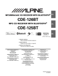
HCE-C117D
D IRECT CONNEC TION REAR VIEW CAMERA
CAMERA DE RECUL AVEC CONNEX ION DIRECTE
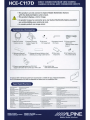
• High visibility in day and night
• Wide viewing angle
• Easy install (small size W23.4xH 23.4xD 19.3mm, Mounting bracket included)
• Excellente vision de jour comme de nuit
• Large ang le de vue
• Parfaite integratio n (taille reduite L:23 .4xH:23.4 xP: 19.3mm, support compris)
Day Image
Vision de jour
Image
ALPINE ELECTRONICS, INC.
www.alpin e.com
HCE-C117D
DIRECT CONNECTION REAR VIEW CAMERA
CAMERA DE RECUL AVEC CONNEXION DIRECTE
• This product can only connect to Alpine Mobile Multimedia Stations
with the dedicated Alpine camera input.
• This product displays a mirror image.
• Ce produit ne peut se connecter qu' a une Station Multimedia Alpine possedant
une entree dediee pour camera de recul.
• La camera produit une image miroir.
Accessories I Accessoi res
x2
CD Rearview camera
I Camera de recul
® Camera mounting
bracket I Support de
fixation
@ Hex screw
I Vis hexagonale
@ Hexagonal wrench
I Cle 6 pans
@ Camera extension
cable(1 O.Sm)
I Rallonge cable camera
(1 O.Sm)
~
@ Waterproofing pad
I Protege cable etanche
(J) Waterproofing pad adhesive sheet
I Adhesif pou r protege cable etanche
@ Camera mounting bracket for KTX-C10LP
I Support de fixation de Ia camera pour KTX-C10LP
e
e
@ Wire clamp
I Attache fils
x4
® Self-tapping screw
I Vis autotaraudeuse
@ Heat shrink tube
I Tube thermoretractable
Optional KTX-C10LP license plate frame mounting kit is available for easy, integrated installation.
Le kit d'adaptation KTX-C10LP est disponible en option pour une installation facile.
KTX-C10LP
Spec/Specifications
Automatic exposure control, Automatic white balance asjustment
Power Requirements
6.0V DC(S.S to 6.5V allowable)
Automatic Image Adjusting Function
Ground Type
Negative ground type
Synchro-System
Internal synchronization
Max. Power Consumption
0.9W
Luminance SIN
40dB or more
300 TV lines or more(center area)
Output Image
Mirror image, NTSC Video signal
Resolution(horizontal)
Image Output impedance
1Vp-p(750)
Illumination Range
Image Sensor
114 Type Color CMOS Image sensor,aspect ratio 4:3
Operating Temperature Range
Camera Section -22 to+ 1S8F(·30 to +70"C)
Storage Temperature Range
-40 to +18SF(-40 to +85'C)
1.51x or more(SO IRE or more)
Effective Number of Pixels
640(horizontai)X 480(vertical) app roximately 0.3 Mega pixels
Lens Section
Focal length f•1.16mm Brightness F:2 .8
External Dimensions(W x H X D)
camera Section 23.4 X 23.4 X 19.3mm{except projection on the rear)
Angle of Field
Horizontal: approximately 12T Vertical: approximately 101 '
Weight
camera Section 3Sg{induding the cable without the brackett and Screw)
Alimentation N cessaire
6.0V continu{S.S a 6.5V acceptable)
Fonction ajustement automatique de !'image
Contr61e automatique de !'exposition, r~lage automatique de Ia balance dH blancs
l)lpe de Masse
Masse degative
Systeme de synchronisation
Synchronisation interne
Consommation maximale
0.9W
Rapport Signal/Bruit
40d8 et plus
Sortie Video
Image miroir,VBCS(Standard NTSO
Resolution(horizontale)
300 !ignes de Ulevision(centrale)
Sortie Image
1Vp-p(7Sn)
Plage d 'illumination
1.5 he et plus
Image senseur
Capteur CMOS couleur type 1/4,ratio 4:3
Tem~rature
de fonctionnement
Camera ·30 a +70' C
Nombre de pixels
640(horizontai)X480(vertical) approximativement 0.3 Mega pixels
Tem~rature
de stockage
-40 a +8S'C
Lentille
Distance focale fz 1.16mm luminosite F•2 .8
Dimensions externes(l X H x P)
camera 23.4 x 23.4 x 19.3mm(sauf partie arriere de Ia camera)
Champ de vision
Horizontal: approximativement 127' Vertical: approximativement 101 '
Poids
Camera 35g(y compris le dble)
NE PAS AFFRANCHIR
IBID
'-
mmm
IBRS/CCRI No. 320
NO POSTAGE
NECESSARY
IF MAILED
TO THE
UNITED STATES
INTERNATIONAL BUSINESS REPLY MAIL/REPONSE PAYEE
TORRANCECA
PERMIT HO. 320
POSTAGE WILL BE PAID BY ADDRESSEE
ALPINE ELECTRONICS
19145 GRAMERCY PL
TORRANCE CA 90501-9876
UNITED STATES OF AMERICA
11.1 •• II, 1.1.11.
I II
i
II I II
111.1,,1 1.1 ... 1.11 .1.1.1
II
II
FOR USE IN CANADA, PLEASE FOLD HERE AND ENSURE THAT
CANADIAN ADDRESS FACES UP.
·dn S3JV.:l SS3CIOOV NVJICI3111N
.lVH.l3CinSN3 ONV 3CI3H OlO.:l 3SV3ld 'VSn Nl 3Sn CIO.:l
l
11 1"1'1'11'"'1'1 1'1 1'1 '11'1'1' '11"1'11
111
11
11
11
II
6£66-60906 VJ 3 JNVCICIO.l
6S8l X08 Od
JNI VJICI311\1V .::10 SJINOCI.lJ3l3 3NidlV
S3JI/\CI3S 8NI.l3>tCIVII\I NOI.lN3.l.lV
33SS3Cl OO'v' A8 Ol'v'd 3 8 111M 38'v'lSOd
'v':::l 3 8 N'v'ClCl01
OZ£ "ON li~Cl 3d
1 1'v' ~
SS'v'1:::>-1SCl l:l
liVV\1 A ld 3 ~ SS3 NISn8
S31'v'1 S 0311 Nn
3 Hl Nl
0311VV.J :II
ACl'v'SS383 N
38'v'l SOd ON
'
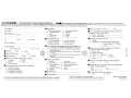
//7#'/ILPINE. Customer Care Registration
• • • • For easy on line registration, go to"w ww alpine-usa . com / registrat io n"
Thank you for choosing Alpine! Register your product to protect your investment and receive up-to-date product in f ormation.
First name:
•
Last name: ____________
Home address :
Street address
State/ P rov.
City
Z ip/POStal Code
•
Phone number: (
E-mail Address :
May we contact you?
•
Gender
•
Date of Birth Month:
•
1. D Male
Marital Status
1. D Yes 2. D No
2. D Female
Year:
1. D Single
-----
2. D Married
•Which ethnicity best describes yourself:
1. lJ Caucasian
4. D Asian
2. :J Hispanic
5. D Other ______
3. D African-American
•Your highest level of education completed:
1. D High School Student
2. D High School Graduate
3. D 2 Yr. Degree/Some College
4. D Completed 4 Yr. College
5. D Completed Graduate School
6. [ ]
7. D
8. 0
9. 0
10. D
Household Income
1. D Less than $30,000
2. 0 $30,000 - $50,000
3.
$5o.ooo - $7o,ooo
4. D $7o,ooo - $9o,ooo
5. D $9o,ooo - $11o,ooo
6. D Over $110,000
n
n
~--~---------------------
. Date of Pu rc h ase:
Occupation
1.
Executive/Managerial
2. L Secretarial/Clerical
3. 0 Sales
4. D General Labor
5. 0 Professional
EngineeringfTechnical
Agriculture
Retired
Student
Other ___________
•Which of the following statements best describes you?
1. D I usually have more electronic equipment than my friends
2. 0 I am usually one of the first of my friends to buy the newest
electronic equipment
3. D I usually wait until a product has been out for a while before
_ I purchase it
4. 0 I am usually one of the first of my friends to know about the
newest car
5. 0 I usually know more about cars than my friends
•
Product purchased
7. :=J Subwoofer
1. D Head unit
8. D Multi-Channel Solution
2. LJ AN Head unit
9. D Rear Seat Entertainment
3. 0 Factory Integration
Technology
10. D iPod Solutions
4. U Installed Navigation 11. D Marine
12. 0 Other _______________
5. D Amplifier
6. 0 Speaker
•
Model Number: ----- - - -- -- -- -- - - -- - - - - - -
•
Serial Number: ______________________
I Thank you for your cooperation! We value your privacy. This information will remain confidential with Alpine and its affiliates.
Month : ______ Year: _ __
• I f you purchased a navigation s y stem, which A/V
Head unit d id you purchase ?
1. 0 Alpine -+ (Model No.)
2. D Other -+ (Brand Name.,..)_______________________
.Purpose of buying th is unit:
1. D Addition
2. D Replacement • Previous b rand replaced?
1. D Factory installed 2. D Alpine
3. O Other _ _ _ _ _ _ ___
•when you purchased th i s Alp ine unit, did you
c ompare it with other brands?
1.0 Yes 2. U No.
If yes, select all that apply.
1. Pioneer 2. D Kenwood 3. D Sony
4. U JVC
5. 0 JL
6. D Rockford
7. D Other: _______
n
•
Have you purchased Alpine prod ucts before?
1. D Yes
2. [_I No
•
Please te ll us the type of veh icle y ou installed t he
Alpine component(s) into:
Make: ___________
Model: ___________
(/)
m
)>
r
I
m
:II
m
Model Year: _____
•How was t h is vehicle purchased ?
1. D Buy
2. [J Lease
Customer Care Registration is for Product registration.
Failure to complete and return this card does not diminish your warranty rights.
PART NO. 68-1 0872Z58-A
M3544125010