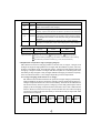
1
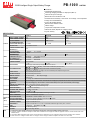
PB-1000
1000W Intelligent Single Output Battery Charger
series
Features :
Controlled by microprocessor
2/3/8 stage charging selectable on output panel (Note 4)
Universal AC input / Full range
Built-in active PFC function PF>0.95
Protection: Reverse Polarity / Short circuit / Over voltage / Over temperature
Charger for lead-acid batteries
3 color LED loading indicator
Built-in remote ON-OFF control
2-Bank charger
Temperature compensation function
FAN on/off control (depends on charging current)
3 years warranty
..
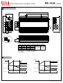
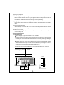
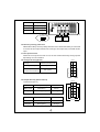
SPECIFICATION
MODEL
OUTPUT
PB-1000-12
PB-1000-24
PB-1000-48
BOOST CHARGE VOLTAGE
14.4V
28.8V
57.6V
FLOAT CHARGE VOLTAGE
13.8V
27.6V
55.2V
OUTPUT CURRENT
60A
34.7A
17.4A
200 ~ 600Ah
120 ~ 350Ah
60 ~ 175Ah
88%
89%
RECOMMENDED BATTERY
CAPACITY(AMP HOURS)(Note 3)
BATTERY TYPE
LEAKAGE CURRENT FROM
BATTERY (Typ.)
INPUT
Open & Sealed Lead Acid
<1mA
VOLTAGE RANGE
90 ~ 264VAC
FREQUENCY RANGE
47 ~ 63Hz
EFFICIENCY (Typ.)
85%
POWER FACTOR (Typ.)
0.95/230VAC
AC CURRENT (Typ.)
INRUSH CURRENT (Typ.)
12A/115VAC
25A/115VAC
LEAKAGE CURRENT
<3.5mA / 240VAC
OVER VOLTAGE
16 ~ 18V
32 ~ 35V
Protection type : Shut down o/p voltage, re-power on to recover
PROTECTION
OVER TEMPERATURE
127 ~ 370VDC
0.98/115VAC at full load
5.2A/230VAC
50A/230VAC
80
5
(12V), 85
5
(24V,48V) (TSW1: detect on heatsink of power transistor)
85
5
(12V),75
5
(24V,48V) (TSW2 : detect on heatsink of o/p diode)
64.5 ~ 69.5V
Protection type : Shut down o/p voltage, recovers automatically after temperature goes down
SHORT CIRCUIT
FUNCTION
YES, protected by internal circuit
REVERSE POLARITY
YES, protected by internal circuit
REMOTE CONTROL
Open: Normal work
BATTER BANKS
2 banks (A & B)
FAST CHARGE
2 / 3 / 8 stage selectable
Short: Stop Charging
CHARGER OK
Relay contact rating(max.): 30V/1A resistive ; "Short" when the unit is working properly, "Open"when the unit is failure or the protection function is activating
OUTPUT OK
Relay contact rating(max.): 30V/1A resistive ; "Short" when the battery is full, "Open" when the battery is still charging
TEMPERATURE COMPENSATION By NTC, compensate both banks at the same time
WORKING TEMP.
-20 ~ +60 (Refer to output load derating curve)
20 ~ 90% RH non-condensing
WORKING HUMIDITY
ENVIRONMENT STORAGE TEMP., HUMIDITY -40 ~ +85 , 10 ~ 95% RH
TEMP. COEFFICIENT
0.05%/ (0 ~ 50 )
VIBRATION
10 ~ 500Hz, 2G 10min./1cycle, 60min. each along X, Y, Z axes
UL60950-1, TUV EN60950-1 approved
SAFETY STANDARDS
SAFETY &
EMC
(Note 2)
OTHERS
WITHSTAND VOLTAGE
I/P-FG:1.5KVAC
O/P-FG:0.5KVAC
I/P-O/P, I/P-FG, O/P-FG:100M Ohms / 500VDC / 25
EMI CONDUCTION & RADIATION Compliance to EN55022 (CISPR22)
/ 70% RH
HARMONIC CURRENT
EMS IMMUNITY
Compliance to EN61000-3-2,-3
Compliance to EN61000-4-2,3,4,5,6,8,11; ENV50204, EN55024, light industry level, criteria A
MTBF
DIMENSION
127.4Khrs min.
PACKING
NOTE
I/P-O/P:3KVAC
ISOLATION RESISTANCE
MIL-HDBK-217F (25
)
300*184*70mm(L*W*H)
3.5Kg; 4pcs/15Kg/1.83CUFT
1. All parameters NOT specially mentioned are measured at 230VAC input, rated load and 25 of ambient temperature.
2. The power supply is considered a component which will be installed into a final equipment. The final equipment must be re-confirmed that it still meets
EMC directives.
3. This is Mean Well's suggested range. Please consult your battery manufacturer for their suggestions about maximum charging current limitation.
4. Please choose the "3 stage" selection when the charger is used to charge the batteries and power the loads in the same time.
File Name:PB-1000-SPEC 2011-01-18
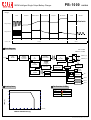
PB-1000
1000W Intelligent Single Output Battery Charger
Mechanical Specification
Case No. 804B
series
Unit:mm
300
70
155
72.6
7
OFF
AC INPUT
ON/OFF
SWITCH
22
B
INLET
B
A
Stage 8/3/2
1 2
3 4
5 6
7 8
9 10
ON
10
A
22
184
A
Air flow
direction
70
48
26.5
A
Stage 8/3/2
9 7 5 3 1
10 8 6 4 2
Control Pin No. Assignment(CN100) : HRS DF11-10DP-2DS or equivalent
Pin No.
1,2
3,4
5,6
7
Assignment
RY13
RY14
RY15
GND
RY13 : Bank A OK
RY14 : Bank B OK
RY15 : Charger OK
Pin No.
8
9
10
Terminal
Assignment Mating Housing
NTC(5K )
RCHRS DF11-10DS HRS DF11-**SC
or equivalent or equivalent
RC+
NTC / GND : Temperature sense
RC+ / RC-: Remote ON/OFF
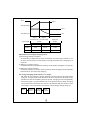
Charging Curve
2 Stage
3 Stage
Start
Start
V boost
V boost
V float
Charge Voltage
Charge Voltage
100%
Charge Current
stage 1
Color of LED
10%
Constant Current Constant Voltage
stage 2
Orange
100%
Charge Current
Battery Full
Green
Constant Current Constant Voltage
stage 1
Color of LED
stage 2
Orange
Float
10%
stage 3
Green
File Name:PB-1000-SPEC 2011-01-18
PB-1000
1000W Intelligent Single Output Battery Charger
series
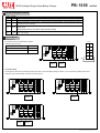
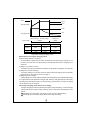
8 Stage
Pulse
Soft Start
Constant Current
Constant Voltage
Analysis
Recondition
Float
Maintain
stage 1
stage 2
stage 3
stage 4
stage 5
stage 6
stage 7
stage 8
Charge Voltage
Charge Current
Orange
Color of LED
Green
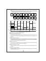
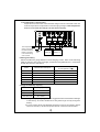
Block Diagram
PFC : 95KHz
PWM fosc : 60KHz
ACTIVE
INRUSH
CURRENT
LIMITING
EMI
FILTER
I/P
RECTIFIER
&
PFC
POWER
SWITCHING
BANK A (+V)
RECTIFIER
&
FILTER
BANK B (+V)
PFC
CONTROL
PWM
CONTROL
AUX
POWER
CURRENT
DETECTION
MCU
2/8
STAGE
SELECT
FAN
OTP
Derating Curve
REVERSE
DETECTION
REMOTE
CONTROL
RC
Bank A OK
RY13
Bank B OK
RY14
Charger OK
RY15
The Function of LEDs
Battery
Fail
Charging
Battery Full
100
80
Color of LED
Red
Orange
Green
LOAD (%)
60
40
20
-20
0
10
20
30
40
50
60
70 (HORIZONTAL)
AMBIENT TEMPERATURE ( )
File Name:PB-1000-SPEC 2011-01-18
PB-1000
1000W Intelligent Single Output Battery Charger
series
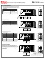
Function Description of CN100
Pin No. Function Description
1,2
RY13 Relay contact rating(max.) : 30V/1A resistive. ; "Short" when the battery A is full, "Open" when the battery A is still charging.
3,4
RY14 Relay contact rating(max.) : 30V/1A resistive. ; "Short" when the battery B is full, "Open" when the battery B is still charging.
Relay contact rating(max.) : 30V/1A resistive. ; "Short" when the unit is working properly, "Open" when the unit is failure or
5,6
RY15
the protection function is activating.
7,8
Temperature sensor comes along with the charger can be connected to the unit to allow temperature compensation of the
GND / RTH charging voltage.
If the temperature sensor is not used, the charger still works normally.
9,10
RC- / RC+
Turn the output on and off by electrical or dry contact between pin 10 (RC+) and pin 9(RC-), "Open" : Normal work ,
"Short" : Stop charging
Function Manual
1.Remote Control
The charger can be turned ON/OFF by using the
"Remote Control" function.
Between RC+(pin10) and RC-(pin9)
CN100
1 RY13 RY13 2
Charger
A
SW Open
ON
SW Short
OFF
RY14 RY14
B
B
A
RY15 RY15
Stage 8/3/2
1
3
5
7
9
GND RTH
2
4
6
8
10
9
RC- RC+
10
SW
+
+
-
Battery B
-
Battery A
2.Two Battery Banks
The charger may be hooked up two battery banks (A and/or B). Connect the battery bank(s) as below. If you are connecting 2 battery banks in the
same time, keep in mind that they must share a common ground.
A
A
B
B
A
B
Stage 8/3/2
1
3
5
7
9
B
A
Stage 8/3/2
2
4
6
8
10
1
3
5
7
9
+
-
Battery A
2
4
6
8
10
+
-
Battery B
A
B
B
A
Stage 8/3/2
1
3
5
7
9
2
4
6
8
10
+
-
Battery B
+
-
Battery A
File Name:PB-1000-SPEC 2011-01-18
PB-1000
1000W Intelligent Single Output Battery Charger
series
3. 2,3, or 8 stage Charging Select
(1)The charger features user selectable 2,3, or 8 stage charging.
The charging profile is selected by moving the slide switch on
the back panel.
CN100
1 RY13 RY13 2
Switch
Charging mode
Right
2 stage charging
Middle
3 stage charging
A
Left
B
B
RY14 RY14
A
RY15 RY15
Stage 8/3/2
1
3
5
7
9
8 stage charging
2
4
6
8
10
GND RTH
(2)Please choose the "3 stage" selection when the charger
is used to charge the batteries and power the loads in the
same time.
9
-
+
Stage 8/3/2
-
+
Battery B
Battery A
4.Charger OK Relay(RY15)
Charger
RC- RC+ 10
CN100
Between pin5 and pin6(RY15)
1 RY13 RY13 2
A
Normal work
ON (Short)
B
B
Failure or the protection
function is activating
OFF (Open)
A
RY14 RY14
Stage 8/3/2
1
3
5
7
9
RY15 RY15
2
4
6
8
10
GND RTH
9
+
-
+
Battery B
RC- RC+ 10
RY15
-
Battery A
5.Output OK Relay(RY13 & RY14)
CN100
1.Bank A OK (RY13)
Bank A
Between pin1 and pin2(RY13)
1
Color of LED A
RY13 RY13
2
A
Battery A Full
ON (Short)
Green
Charging
OFF (Open)
Orange
B
B
2.Bank B OK (RY14)
Bank B
Between pin3 and pin4(RY14) Color of LED B
Battery B Full
ON (Short)
Green
Charging
OFF (Open)
Orange
A
RY14 RY14
Stage 8/3/2
1
3
5
7
9
RY15 RY15
2
4
6
8
10
GND RTH
9
+
-
+
Battery B
RY14
-
RY13
Battery A
6.Temperature Compensation
Temperature sensor comes along with the charger can
be connected to the unit to allow temperature compensation
of the charging voltage.
If the temperature sensor is not used, the charger still
works normally.
RC- RC+ 10
CN100
1 RY13 RY13 2
A
B
B
A
RY14 RY14
Stage 8/3/2
1
3
5
7
9
RY15 RY15
2
4
6
8
10
GND RTH
9
+
-
Battery B
+
RC- RC+ 10
-
Battery A
NTC
The temperature sensor can either be attached to the
battery or placed in its surrounding environment.
File Name:PB-1000-SPEC 2011-01-18
PB-1000
Instruction Manual
PB-1000 Instruction Manual
Index
0.Product description................................................................................. 1
1.Notes on operation ................................................................................. 1
2.Front and back panel .............................................................................. 1
3.Derating curve ........................................................................................ 2
3.1 Charging current VS temperature ...................................................... 2
4.Function description for CN100 ............................................................... 2
5.LED Indication ........................................................................................ 3
6.Explanation of operation logic (charging stages)...................................... 3
6.1 2 stage charging (flick switch to "2" stage) ......................................... 3
6.2 3 stage charging (flick switch to "3" stage) ......................................... 4
6.3 8 stage charging (flick switch to "8" stage) ......................................... 5
7.Function description ............................................................................... 7
7.1 Input voltage .................................................................................... 7
7.2 PFC ................................................................................................. 7
7.3 Remote control ................................................................................. 7
7.4 Two battery banks ............................................................................ 8
7.5 2, 3, or 8 stage charging mode selection ........................................... 8
7.6 Reverse polarity protection ............................................................... 9
7.7 Fan speed control ............................................................................. 9
7.8 Charger OK relay (RY15) .................................................................. 9
7.9 Output OK relay (RY13 & RY14) ....................................................... 9
7.10 Temperature compensation ............................................................ 10
8.Temperature compensation .................................................................... 10
9.Suggested battery capacity ..................................................................... 10
10.Series and parallel connection of batteries ............................................ 11
11.Failure correction notes ........................................................................ 11
Jan. 2011 Version 6
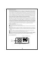
0.Product description
PB-1000 is MW's next generation smart charger. It has many of the protective features
that consumers would like to have in a charger including battery misconnection
(wrong voltage), reverse polarity, battery disconnection or not connected, and battery
failure analysis. The latest high efficiency switching topology plus microcontroller
power management are utilized in its design. Three types of charging curves are
offered for lead acid battery charging, 2 stages for quick charging, 3 stages (quick +
float), and 8 stages for optimized charging. Charging stage selection can be easily
made by the user through the selection switch on the front panel.
Depending on battery brand and type (lead acid, gel, lithium iron, and lithium manganese);
the battery may require special charging curves and adjustment to the protective
functions which differs from the standard settings. The charging curves and protective
functions can be customized by reprogramming its firmware. Basically, you can change
the voltage/current settings of each individual stage plus adjust or cancel the protective
functions. Please note, the factory charging curve is for charging lead-acid battery.
Please contact MW regarding other types of battery charging requirements.
1.Notes on operation:
Designed for charging lead acid battery.
Must be installed in a dry and well ventilated area. It should not be exposed to rain
or snow.
The cables between charger and battery should be kept as short as possible to
prevent excessive voltage drop. Too much voltage drop will lead to longer charging
period.
Please make sure charging voltage and current meets battery specification.
Refrain from connecting new and old batteries in series.
Charger should be in the OFF mode before making battery connection or disconnection.
Three years warranty is provided under normal operating conditions. Failure
resulting from improper operation will result in cancellation of warranty.
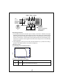
2.Front and back panel
AC INLET ON/OFF SWITCH
ON
Fan
Ventilation
Hole
OFF
AC INPUT
Figure 2.1 Front Panel
1
Battery B Battery A Common
Positive
Positive Negative
LED
Indicator
2/3/8 stage
selection switch
Function
Connector
1
3
5
7
9
A
{
B
B
A
Stage 8/3/2
1
3
5
7
9
2
4
6
8
10
2
4
6
8
10
+
-
Battery B
+
-
Battery A
Figure 2.2 Back Panel
WARNING :
Please check battery
polarity before
connection
Assembly guidelines:
1.The charger should be turned OFF prior to battery connection. Suitable wire gauge
should be chosen based on rated charging current of the charger unit. Double-check
battery polarity before making the battery connection. Positive terminal of the charger
must be connected to + of the battery and negative terminal to of the battery. Also,
make sure the positive and negative terminals of the charger are not accidentally
shorted together.
2. After plugging in the AC power cable, flick the ON/OFF (0/-) switch to the ON(-)
position. The LED indicator on the switch will light up.
3.Derating curve
3.1 Charging current VS temperature
100
80
LOAD (%)
60
40
20
-20
0
10
20
30
40
50
60
70 (HORIZONTAL)
AMBIENT TEMPERATURE ( )
4.Function description for CN100
Pin No.
1,2
Function Description
RY13
Relay contact rating (max.): 30V/1A. "Short" when bank A is full.
"Open" when bank A is still charging.
2
Pin No.
Function Description
3,4
RY14
5,6
RY15
Relay contact rating (max.): 30V/1A. "Short" when bank B is full.
"Open" when bank B is still charging.
Relay contact rating (max.): 30V/1A. "Short" when the unit is working
properly. "Open" when the unit has failed or protection has activated.
7,8
Temperature sensor which comes with the charger can be connected
to the unit to allow temperature compensation of the charging voltage.
GND/RTH
If the temperature sensor is not used, the charger can still work
normally.
9,10
RC-/RC+
Turn the output ON and OFF by electrical or dry contact between
pin10 (RC+) and pin9 (RC-). Open: start charging. Short: stop charging.
5.LED Indication
Color of LED
Orange
Green
Red
Battery status
Charging
Battery full
Fail
Types of failure: 1 Battery disconnected 2 Damaged battery
3 Reverse polarity
4 Incorrect battery voltage (e.g. PB-1000-12 connected to 24V battery)
5 Activation of protection function (e.g. OTP, OVP, and Short)
6.Explanation of operation logic (charging stages):
PB-1000 has a total of 3 charging modes to choose from, 2 stages, 3 stages, and
8 stages. 8 stages charging differ from 2 stages with the addition of pulse, soft start,
analysis, recondition, float, and maintain stages. 2 stages provide simple and quick
charging. 3 stages is similar to 2 stages with the exception of not shutting OFF after
the battery is fully charged. Lastly, 8 stages will allow charging to maximum capacity.
User can select between 2,3 or 8 stages depending on their requirement.
6.1 2 stage charging (flick switch to "2" stage)
PB-1000 has channels A & B which can perform 2 stages charging individually.
Channel A will be the first to commence charging. During initial charge (stage 1),
charger will provide maximum current to the battery. The built-in fan will also turn
ON. As the battery starts to get full, charging current will gradually decrease
(stage 2). When charging current decrease to less than 10% of max. LED indicator
will turn Green to show a full charge. Channel A will turn OFF while charging
commence at Channel B. After the battery at channel B is fully charged, PB-1000
will turn OFF its outputs.
Start
Bank A
Constant
Current
Bank A
Constant
Voltage
Bank A
Charging
Ends
3
Bank B
Constant
Current
Bank B
Constant
Voltage
Bank B
Charging
Ends
Start
V boost
Charge Voltage
100%
10%
Charge Current
stage 1
stage 2
Constant Current
Constant Voltage
Orange
Color of LED
Battery Full
Green
State
PB-1000-12
PB-1000-24
PB-1000-48
Constant
Current
60A
34.7A
17.4A
V boost
14.4V
28.8V
57.6V
Figure 6.1 2 stage charging curve
Explanation for 2 stages charging curve
(0)Initial stage (battery analysis):
Check battery voltage level to see if it is within the normal range, whether or not
a battery is connected, or if the battery is already full and further charging is not
required.
(1)Stage 1 (constant current):
A constant current is provided so the battery can be quickly charged to 2.4V per cell.
(2)Stage 2 (constant voltage):
A constant voltage of 2.4V per cell is provided until the charging current naturally
tapers down to 10% then stop charging.
6.2 3 stage charging (flick switch to "3" stage)
PB-1000 can only perform 3 stages charging to Channel A. During initial charge
(stage 1), charger will provide maximum current to the battery. The built-in fan
will also turn ON. As the battery starts to get full, charging current will gradually
decrease (stage 2: programmed to last no longer than 24hrs). When charging
current decrease to less than 10% of max. LED indicator will turn Green to show
a full charge. The charger will now maintain a float charge voltage (stage 3).
Start
Bank A
Constant
Current
Bank A
Constant
Voltage
Bank A
Float
Charge
4
Start
V boost
V float
Charge Voltage
100%
10%
Charge Current
stage 1
Constant Current
stage 2
stage 3
Constant Voltage
Battery Full
Orange
Color of LED
Green
State
PB-1000-12
PB-1000-24
PB-1000-48
Constant
Current
60A
34.7A
17.4A
V boost
V float
14.4V
13.8V
28.8V
27.6V
57.6V
55.2V
Figure 6.2 3 stage charging curve
Explanation for 3 stages charging curve
(0)Initial stage (battery analysis):
Check battery voltage level to see if it is within the normal range, whether or not
a battery is connected, or if the battery is already full and further charging is not
required.
(1)Stage 1 (constant current):
A constant current is provided so the battery can be quickly charged to 2.4V per cell.
(2)Stage 2 (constant voltage):
A constant voltage of 2.4V per cell is provided until the charging current naturally
tapers down to 10% then move on to stage 3.
(3)Stage 3 (Float voltage):
A float voltage of 2.3V per cell is provided so that the battery can maintain full charge.
*For applications that utilize the charger (PB-1000) to charge batteries and supply.
System power simultaneously(e.g. UPS system), please select "3 stage" charging
for the best use of the charger.
6.3 8 stage charging (flick switch to "8" stage)
8 stage charging provides optimized charge to lead acid battery. It also prolongs
battery life and increase storage capacity. Some of the main advantages are as
below:
Advantage of pulse stage: Use pulse current to revive aged battery.
Advantage of recondition stage: Allow full charge of battery.
5
Advantage of float and maintain stage: After LED turns green, maintenance
charge is provided so the battery is always in a full state. User will have access
to a full battery whenever it is disconnected from the charger.
Start
Bank A
Pulse
Charge
Bank A
Soft
Start
Bank A
Constant
Current
Bank A
Constant
Voltage
Bank A
Analysis
Bank A
Recondition
Bank A
Float
Charge
Bank A
Maintain
Bank B
Pulse
Charge
Bank B
Soft
Start
Bank B
Constant
Current
Bank B
Constant
Voltage
Bank B
Analysis
Bank B
Recondition
Bank B
Float
Charge
Bank B
Maintain
A/B maintain charge cycle
Pulse
Soft
Start
Constant
Current
Constant
Voltage
Analysis
Recond
Float
stage 1
stage 2
stage 3
stage 4
stage 5
stage 6
stage 7
Maintain
Charge
Voltage
Charge
Current
Color of
LED
Orange
stage 8
Green
Figure 6.3 8 stage charging curve
Explanation for 8 stages charging curve
(0)Initial stage (battery analysis):
Check battery voltage level to see if it is within the normal range, whether or not
a battery is connected, or if the battery is already full and further charging is not
required.
(1)Stage 1 (pulse charging):
Pulse charging is used to revive tired lead acid battery which is either improperly
charged/discharged or allowed to self-discharge as occurs during non-use. Basically,
help to restore its normal chemical properties.
(2)Stage 2 (soft start):
Use low charge voltage and current to prepare the battery to accept upcoming
bulk charging, so a better charge can be applied.
(3)Stage 3 (constant current):
A high constant current is provided so the battery can be quickly charged to 2.4V
per cell.
(4)Stage 4 (constant voltage):
A constant voltage of 2.4V per cell is provided until the charging current naturally
tapers down to a low level.
6
(5)Stage 5 (analysis):
The charger will stop charging for 2 minutes to determine battery status. If the
battery voltage is higher than 2.1V per cell, the battery is determined as OK and
will move on to stage 6. If the battery voltage is lower than 2.1V per cell, the battery
fail indication will come ON and the charger will stop charging.
(6)Stage 6 (recondition boost charge):
Boost voltage is provided to recondition the battery storage capacity to its original
state.
(7)Stage 7 (float charge):
A float voltage of 2.3V per cell is provided for extended period of time so that the
battery can maintain full charge.
(8) Stage 8 (maintain):
Maintenance charge is provided to compensate for battery self-discharge and
extend battery life.
7.Function description
7 .1 Input voltage
Input voltage range is 90~264Vac or 127~370Vdc.
The provided input voltage must fall within the specified range otherwise the
unit may be non-functional also the active PFC circuit may fail or get damaged.
7.2 PFC
Built-in active PFC circuit: PF>0.95 when input voltage is between 90~230Vac
with full load at the output. On the other hand, if the input voltage is >230V or
output is not at full load, the PF will drop below 0.95.
7.3 Remote control
The charger can be turned ON/OFF by using the "remote control" function.
Between RC+ (pin10)
and RC- (pin9)
Charger
SW open
ON
SW closed
OFF
CN100
1 RY13 RY13 2
A
A
B
B
RY14 RY14
Stage 8/3/2
RY15 RY15
1 2
3 4
5 6
7 8
9 10
GND RTH
9
+
-
Battery B
+
SW
Battery A
7
RC- RC+
10
7.4 Two battery banks
The charger can be hooked up to two battery banks (A and/or B). Connect the
battery bank(s) as below. If you are connecting 2 battery banks at the same time,
keep in mind that it must share a common ground.
A
A
B
B
Stage 8/3/2
1
3
5
7
9
2
4
6
8
10
+
-
Battery A
A
A
B
B
Stage 8/3/2
1 2
3 4
5 6
7 8
9 10
+
-
Battery B
A
A
B
B
Stage 8/3/2
1
3
5
7
9
2
4
6
8
10
+
-
Battery B
+
-
Battery A
7.5 2, 3, or 8 stage charging mode selection
The charger features user selectable 2, 3, or 8 stage charging. The charging
profile is selected by moving the slide switch on the back panel.
8
Switch
Slide right
Charging mode
A
2 stage charging
Middle
3 stage charging
Slide left
8 stage charging
A
B
B
Stage 8/3/2
1 2
3 4
5 6
7 8
9 10
Stage 8/3/2
+
-
Battery B
+
-
Battery A
7.6 Reverse polarity protection
With built-in battery reverse polarity detection circuit. When the battery is connected
in reverse at the output terminal of the charger, the output relay circuit will remain
open.
7.7 Fan speed control
With built-in fan speed control circuit, the fan will automatically change speed
depending on load condition.
7.8 Charger OK relay (RY15)
Charger
CN100
Between pin5 and pin6
Working normally
ON (short)
Failure or protection
function has activated
OFF (open)
1 RY13 RY13 2
RY14 RY14
RY15 RY15
GND RTH
9
RC- RC+ 10
RY15
7.9 Output OK relay (RY13 & RY14)
1.Bank A OK (RY13)
Bank A
CN100
1
Between pin1 and pin2 Color of LED A
Bank A full
ON (short)
Green
Charging
OFF (open)
Orange
2.Bank B OK (RY14)
Bank B
Bank B full
ON (short)
Green
Charging
OFF (open)
Orange
9
2
RY14 RY14
RY15 RY15
GND RTH
9
Between pin3 and pin4 Color of LED B
RY13 RY13
RC- RC+ 10
RY14
RY13
7. 10 Temperature compensation
Temperature sensor which comes with the charger can be connected to the unit
to allow temperature compensation of the charging voltage. If the temperature
sensor is not used, the charger can still work normally.
A
B
B
A
Stage 8/3/2
1
3
5
7
9
The temperature
sensor can either
be attached to the
battery or placed
in its surrounding
environment.
2
4
6
8
10
+
-
Battery B
NTC
+
-
Battery A
8.Wiring for battery
Select suitable wire guage based on rated charging current. Refer to the following
table for minimum wire gauge. We highly recommend using RED wire for + connection
and BLACK wire for-connection:
AWG
CROSS SECTION(mm 2)
Max. Current(A)
UL1015(600V 105 )
14
2.1
12
12
3.3
22
10
5.3
35
7
10
46
6
16
60
4
25
80
9.Suggested battery capacity
Model
Battery capacity
PB-1000-12
200-600AH
PB-1000-24
120-350AH
PB-1000-48
60-175AH
Note: 1.Using battery capacity larger than the suggested value will not lead to damage
of the battery. The main drawback is it may take longer to fully charge the
battery.
2.If you're unsure about max allowable charging current of your battery, please
refer to the battery's technical specification or consult its manufacturer.
10
10.Series and parallel connection of batteries
1.Batteries in series
Voltage can be doubled when 2 batteries are connected in series. However, the
capacity (Ah) will remain the same. For example, 2 x 12V 100Ah batteries connected
in series = 24V 100Ah.
+
+
-
-
Battery
Battery
2.Batteries in parallel
Wh e n 2 b a tte r i e s a r e c o n n e c te d i n p a r a l l e l , vo l ta g e r e m a i n s th e s a m e a n d th e
capacity (Ah) doubles. For example, 2 x 12V 100Ah batteries connected in parallel
= 12V 200Ah.
+
-
Battery
+
-
Battery
11.Failure correction notes
Status
Unable to
charge
the battery
LED indicator
does not turn
Green after a
long charging
period
Possible reasons
Solutions
ON/OFF switch in the OFF position
Switch to the ON position
Battery reverse polarity
Reconnect using the
right polarity
Battery with higher voltage is
connected
Use battery with the
correct voltage
Input AC voltage is too low
Make sure input source
is between 90~264VAC
Battery exceeded lifespan or
damaged
Replace with a new
battery
Output cables are too thin
Replace with suitable
wire gauge
If you are not able to clear the failure condition, please contact Mean Well or
any of our distributors for repair service.
WARNING : This is a class A product. In a domestic environment this product
may cause radio interference in which case the user may be
required to take adequate measures.
11