1
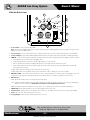
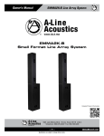
Owner’s Manual
ELI2K-B Line Array System
ELI2K-B
Small Format Line Array System
Detailed Product Information
1601 Jack McKay Blvd. • Ennis, Texas 75119 U.S.A.
Telephone: 800.876.3333 • Fax: 800.765.3435
– 1 –
Specifications are subject to change without notice.
AtlasSound.com
ELI2K-B Line Array System
Owner’s Manual
Table of Contents
Important Safety Instructions .................................................................................................................. 3
Applications............................................................................................................................................. 5
Key Features .......................................................................................................................................... 5
Rear Panel ............................................................................................................................................... 6
Installation................................................................................................................................................ 7
Troubleshooting........................................................................................................................................ 8
Specifications........................................................................................................................................... 9
Warranty................................................................................................................................................. 12
1601 Jack McKay Blvd. • Ennis, Texas 75119 U.S.A.
Telephone: 800.876.3333 • Fax: 800.765.3435
AtlasSound.com
– 2 –
Specifications are subject to change without notice.
Owner’s Manual
ELI2K-B Line Array System
Important Safety Instructions
The lightning flash with arrowhead symbol within an
equilateral triangle, is intended to alert the user to the
presence of uninsulated “dangerous voltage “ within the
product’s enclosure that may be of sufficient magnitude
to constitute a risk of electric shock to persons.
The exclamation point within an equilateral triangle is
intended to alert the user to the presence of important
operating and maintenance (servicing) instructions in the
literature accompanying the product.
1. Read these instructions.
2. Keep these instructions.
3. Heed all warnings.
4. Follow all instructions.
5. Do not use this device near water.
6. Clean only with dry cloth.
7. Do not block any ventilation openings. Install in accordance with the manufacturer’s instructions.
8. Do not install near any heat sources such as radiators, heat registers, stoves, or other device that produce heat.
9. Do not defeat the safety purpose of the polarized or grounding-type plug. A polarized plug has two blades with one wider than the
other. A grounding type plug has two blades and a third grounding prong. The wide blade or the third prong are provided for your safety. If the provided plug does not fit into your outlet, consult an electrician for replacement of the obsolete outlet.
10.Protect the power cord from being walked on or pinched particularly at plugs, convenience receptacles, and the point where they exit from the device.
11.Only use attachments/accessories specified by the manufacturer.
12 This product is equipped with a three-wire grounding-type plug, a plug having a third (grounding) pin. This plug will only fit into a grounding-type power outlet. This is a safety feature. If you are unable to insert the plug into the outlet, contact your electrician to replace your obsolete outlet. Do not defeat the safety purpose of the grounding-type plug.
13.Unplug this device during lightning storms or when unused for long periods of time.
14.Refer all servicing to qualified service personnel. Servicing is required when the device has been damaged in any way, such as power-supply cord or plug is damaged, liquid has been spilled, or objects have fallen into the device, the device has been exposed to rain or moisture, does not operate normally, or has been dropped.
15.WARNING: To reduce the risk of fire or electric shock, this device should not be exposed to rain or moisture and objects filled with liquids, such as a vase, should not be placed on this device.
1601 Jack McKay Blvd. • Ennis, Texas 75119 U.S.A.
Telephone: 800.876.3333 • Fax: 800.765.3435
– 3 –
Specifications are subject to change without notice.
AtlasSound.com
ELI2K-B Line Array System
•
•
•
•
•
•
•
•
•
Owner’s Manual
WARNING When The Device Is In Use
To prevent electric shock, do not remove the product cover as there are high voltage components inside. Refer all servicing to
Atlas Sound.
Should any of the following irregularities occur during use, immediately switch off the power, disconnect the power cord from the AC outlet and contact Atlas Sound. Do not to attempt to continue operation with the product as this may cause fire or electric shock:
• Smoke or strange smell coming from the unit.
• If the product falls or the case is damaged.
• If water or any metallic objects falls into the product.
• If the power supply cord is damaged in any way.
• If the unit is malfunctioning.
Do not insert or drop metallic objects or flammable materials into the ventilation holes of the product's cover, as this may result in electric shock or fire.
Never operate this product or touch the power supply cord during an electrical storm, electric shock may result.
Never exceed the power rating on the product when connecting equipment. Fire and/or property damage may result.
Operate the product only with the voltage specified on the unit. Fire and/or electric shock may result if a higher voltage is used.
Do not modify, kink, or cut the power cord. Do not place the power cord in close proximity to heaters and do not place heavy objects on the power cord, including the product itself, doing so may result in fire or electrical shock.
Ensure that the safety ground terminal is connected to a proper ground. Never connect the ground to a gas pipe as a catastrophic disaster may result.
Be sure the installation of the product is stable, avoid slanted surfaces as the product may fall and cause injury or property damage.
CAUTION When Installing The Product
•
Always make sure your system is set up on a level suface and will not fall over.
•
Always assure power is Off to amplifiers before making any connections. Assure that all electrical equipment is properly grounded.
• Suspension or “flying” speaker systems requires training and expertise. Improper rigging of a flying speaker may result in injury,
death, equipment damage, and legal liability. Installation must be carried out by fully qualified installers, in accordance with all
required safety codes and standards at the place of installation.
A 5:1 design factor is a generally accepted minimum standard. However, legal requirements for overhead suspension vary by
municipality, please consult your local safety standards office before installing any product. We also recommend that you
thoroughly check any laws and bylaws prior to installation.
Loudspeakers flown in theaters, nightclubs, conference centers, or other places of work and entertainment must be provided with
an independent, correctly rated and securely attached secondary safety, in addition to the principle suspension point(s).
If you lack the skills, training, and proper ancillary equipment to fly a speaker system, do not attempt to do so.
For additional information regarding the suspension of loudspeakers or to purchase rigging materials, please contact our friends at
Adaptive Technologies Group,1635 E. Burnett St. Signal Hills, CA 90755 • www.adapttechgroup.com • Telephone (562) 424-1100
•
•
•
•
CAUTION When The Product Is In Use
Never place heavy objects on the product, causing it to fall and/or break, resulting in personal injury and property damage. In addition, the product itself may fall and cause injury and property damage.
All professional loudspeaker systems are capable of generating very high sound pressure levels. Use care with placement and operation to avoid exposure to excessive levels that can cause permanent hearing damage.
Ensure that the power supply plug is securely plugged into the wall outlet. Never allow dust to accumulate on the power plug or inside the wall outlet.
When cleaning the unit or the unit is not to be operated for an extended period, unplug the power cord from the wall.
1601 Jack McKay Blvd. • Ennis, Texas 75119 U.S.A.
Telephone: 800.876.3333 • Fax: 800.765.3435
AtlasSound.com
– 4 –
Specifications are subject to change without notice.
Owner’s Manual
ELI2K-B Line Array System
Applications
The ELI small format Line Array system is desinged for professional audio where clarity of speech and music is most important. This
system is designed for quick and easy set up from truck to stage and back again. It has a very small footprint that can be ready to go
within aproximately 10 minutes. The system will provide audio sound coverage for a space approximately 30' x 65'. Common uses
include:
• Corporate Speaking Events
• Acoustic Performances
• Pre-Recorded Music
• Small Indoor or Outdoor Gatherings
• Ballrooms, Auditoriums, Worship Space, Schools, Boardrooms
Key Features
• Onboard Internal Amplification Modules with On Board DSP
• Fifteen (15) Full Range 3” Proprietary Speakers per EL1503-B Array
•NL4 (Speakon Speaker Connectors)
•Baltic Birch Plywood Construction with Duratex™ Painted Cabinet
• Two DSP Program Settings
ELI2K-B Kit Includes
Qty 2 EL1503-B Line Arrays with Necessary Wiring
Qty 1 ELW110A-B Woofer Cabinet and Power Cable
Qty 1 ELW110X-B Woofer Cabinet and 25' NL4 Speaker Cable
Qty 2 POLE45
Each Atlas A-Line Acoustics speaker system has been built to the highest standard and thoroughly inspected before leaving our
factories. Carefully inspect the shipping carton, then examine and test your new speaker system. If you find any damage, immeddiately
notify the shipping company. Only the consignee may institute a claim procedure.
1601 Jack McKay Blvd. • Ennis, Texas 75119 U.S.A.
Telephone: 800.876.3333 • Fax: 800.765.3435
– 5 –
Specifications are subject to change without notice.
AtlasSound.com
Owner’s Manual
ELI2K-B Line Array System
ELW110A-B Rear Panel
4
5
9
PGM SEL
6
MUTE
CH 1 CH 2
MUTE ON
Pin 1 Array
Pin 2 Subwoofer
PWR
CLIP
PROT
10
SIGNAL
7
VOLUME
LOOPING
OUTPUT
INPUT
ON
8
2
POWERCON
NEUTRIK NAC3FCA
POWER OUTLET
12A MAXIMUM
POWER
1
3
1.
Power Switch– Turns unit power ON or OFF.
Note: There are two programs loaded into the DSP at the factory: When switching between the two programs the power on the
amplifier must be in the OFF positon.
2.
Powercon Input – Connect included Powercon to 3 prong plug to this port in order to deliver electrical power to the amplifier.
3. Powercon Output – Daisy chain multiple amplified speaker systems using this output reducing number of wall plugs required.
4. PGM SEL– There are two programs loaded into the DSP at the factory. When switching between programs, follow these steps:
• The amplifier power switch must be in the OFF positon
• Using the PGM SEL button, press it to the IN or OUT position to make selection.
• Turn the power button switch to the ON position and the new program selection will now be stored.
• When switching between the two programs, repeat the previous steps. If trying to change program with the power ON, the program will not change.
Program button IN mode is typically used for speech and acoustic music.
Program button OUT mode is typically used for prerecorded music, with a + 4db boost on the woofer cabinet.
5. MUTE CH1 & CH2 - There are two mute switches on the unit. When depressed, the channel is active and will play sound. CH1 controls the woofer and CH2 controls the line array. Press either button a second time to activate the mute function.
6. LED Indicators
PWR - Green LED indicates unit is receiving power from wall outlet.
CLIP - Yellow LED indicates that the unit is operating outside its normal range. Reduce output of source unit to avoid damaging speakers or other components. NOTE: This unit can flash occassionally during normal use.
PROT - Red LED indicates the amplifier is in Protect mode. Do not operate the unit when the red LED is illuminated.
7. SIGNAL LED - Green LED indicates the unit is receiving signal from the source unit.
8. Volume Control - Adjusts volume of the speaker unit in reference to the master volume set at the source/mixer, 0 to -36dB.
9. Input - XLR connection delivers signal from source unit.
10.Looping Output - XLR connection delivers signal from source unit.
1601 Jack McKay Blvd. • Ennis, Texas 75119 U.S.A.
Telephone: 800.876.3333 • Fax: 800.765.3435
AtlasSound.com
– 6 –
Specifications are subject to change without notice.
Owner’s Manual
ELI2K-B Line Array System
11.Speakon Output 1 - Connect to Line Array Speakon input to deliver signal to line array speaker.
12.Speakon Output 2- Connect to Speakon input of ELW110X-B unit to transmit signal to second ELI unit.
11
Pin 1 Array
Pin 2 Subwoofer
PGM SEL
MUTE
CH 1 CH 2
MUTE ON
PWR
CLIP
PROT
12
SIGNAL
VOLUME
LOOPING
OUTPUT
POWERCON
NEUTRIK NAC3FCA
INPUT
POWER OUTLET
12A MAXIMUM
ON
POWER
2
EL1503-B Rear Panel
1. Speakon Input 1 - Connect to Subwoofer Speakon output to deliver signal to line array speaker.
2. Speakon Output 1 - Connect to auxiliary line array or to other speaker if necessary.
1
Installation Instructions
1.
Position all speakers in the area in which they need to be set-up. Place both of the subwoofer cabinets (ELW110A-B &
ELW110X-B) upright with the hole for the mounting pole facing up. Locate their positions in the venue making sure they are
on a level surface for the best support for the arrays. Note: The system can be set up slightly behind the performer so that the
performer is hearing the same mix as the audience.
2.
Insert the included 45" pole into the pole mount hole on the subwoofer cabinet. Position the EL1503-B array on top of the pole
making sure the complete system is level. NOTE: The vertical coverage of the EL1503-B is +/- 5° off of the top and bottom of the
cabinet. A shorter mounting pole may be necessary to keep the array energy aimed to cover audience. This shorter pole is optional
and available from Atlas A-Line Acoustics.
3.
Repeat these two steps with the 2nd pair of cabinets.
4.
First, connect the included long NL4 speaker cable between the two subwoofer cabinets. Second, connect the short NL4 cables
from the subwoofer cabinet to the 1503 arrays (it does not matter which NL4 female output is used). Connect your signal male XLR
cable to the input of the amp.
5.
Turn on the unit power and adjust volume as needed.
6.
The system can be dismantled follwing the previous steps in reverse order to ensure proper disconnection and future functionality.
1601 Jack McKay Blvd. • Ennis, Texas 75119 U.S.A.
Telephone: 800.876.3333 • Fax: 800.765.3435
– 7 –
Specifications are subject to change without notice.
AtlasSound.com
ELI2K-B Line Array System
Owner’s Manual
Troubleshooting
Issue 1 - Green Signal light on but there is no sound
Possible Cause - Speaker wiring
Action Needed - Connect cable and make sure NL4 is locked in place (¼ turn clockwise).
Possible Cause - Mute switch is engaged
Action Needed - Disengage the Mute switch.
Issue 2 - Low sound or audio output.
Possible Cause - Input cable may have a short or the cable may be bad.
Action Needed - Cable must be balanced, 3 pin connection.
Possible Cause - Check input cable to be sure it is a balanced 3 pin XLR.
Action Needed - Replace cable as need making sure there is continuty on all 3 pins.
Possible Cause - Check input in is connect to the input not loop out.
Action Needed - Reconnect cable to correct input.
Issue 3 - Sound is intermittent
Possible Cause - Check cable integrity.
Action Needed - Replace damaged or crimped cables as needed.
Possible Cause - Amplifier operating outside normal performance range.
Action Needed - Decrease source output level.
Issue 4 - No Low end to system, woofer not working
Possible Cause - M
ute switch for Channel #1 is engaged.
Action Needed - Disengage mute switch.
Issue 5 - No top end to system, arrays not working.
Possible Cause - Mute switch for Channel #2 is engaged.
Action Needed - Disengage mute switch.
Possible Cause - Speaker cables not conneted from woofer cabinet.
Action Needed - Connect speaker cables and make sure NL4 is locked in place (¼ turn clockwise)
1601 Jack McKay Blvd. • Ennis, Texas 75119 U.S.A.
Telephone: 800.876.3333 • Fax: 800.765.3435
AtlasSound.com
– 8 –
Specifications are subject to change without notice.
Owner’s Manual
ELI2K-B Line Array System
Specifications
Line Array
EL1503-B
RMS Power (Watts)
200
Impedance 8Ω per Cabinet
MAX SPL
107dB
Drivers
Fifteen (15) 3"
Frequency Response
175Hz - 16kHz
Connectors
2 x NL4
Height
49" (124.46cm)
Width
4.25" (10.8cm)
Depth
6.375" (16.2cm)
Weight
29 lbs. (10.4kg)
Subwoofer
ELW110A-B
ELW110X-B
Amplifier Power (Watts)
200
NA
Impedance 8Ω
8Ω
Driver
1 x 10"
1 x 10"
Frequency Response
40Hz - 125Hz
40Hz - 125Hz
Connectors
2 x NL4
2 x NL4
I/O Powercon
NA
M&F XLR
NA
Height
17.5" (44.45cm)
17.5" (44.45cm
Width
13.0" (33.02cm)
13.0" (33.02cm)
Depth
17.5" (44.45cm)
17.5" (44.45cm)
Weight
33 lbs. (15.0kg)
30 lbs. (13.6kg)
1601 Jack McKay Blvd. • Ennis, Texas 75119 U.S.A.
Telephone: 800.876.3333 • Fax: 800.765.3435
– 9 –
Specifications are subject to change without notice.
AtlasSound.com
ELI2K-B Line Array System
Owner’s Manual
Notes:
1601 Jack McKay Blvd. • Ennis, Texas 75119 U.S.A.
Telephone: 800.876.3333 • Fax: 800.765.3435
AtlasSound.com
– 10 –
Specifications are subject to change without notice.
Owner’s Manual
ELI2K-B Line Array System
Notes:
1601 Jack McKay Blvd. • Ennis, Texas 75119 U.S.A.
Telephone: 800.876.3333 • Fax: 800.765.3435
– 11 –AtlasSound.com
Specifications are subject to change without notice.
ELI2K-B Line Array System
Owner’s Manual
Limited Warranty
All products manufactured by Atlas A-Line Acoustics are warranted to the original dealer/installer, industrial or commercial purchaser
to be free from defects in material and workmanship and to be in compliance with our published specifications, if any. This warranty
shall extend from the date of purchase for a period of three years on all Atlas Sound products, including SOUNDOLIER brand, and
ATLAS SOUND brand products except as follows: one year on electronics and control systems; one year on replacement parts;
and one year on Musician Series stands and related accessories. Additionally, fuses and lamps carry no warranty. Atlas Sound will
solely at its discretion, replace at no charge or repair free of charge defective parts or products when the product has been applied
and used in accordance with our published operation and installation instructions. We will not be responsible for defects caused by
improper storage, misuse (including failure to provide reasonable and necessary maintenance), accident, abnormal atmospheres, water
immersion, lightning discharge, or malfunctions when products have been modified or operated in excess of rated power, altered,
serviced or installed in other than a workman like manner. The original sales invoice should be retained as evidence of purchase under
the terms of this warranty. All warranty returns must comply with our returns policy set forth below. When products returned to Atlas
Sound do not qualify for repair or replacement under our warranty, repairs may be performed at prevailing costs for material and labor
unless there is included with the returned product(s) a written request for an estimate of repair costs before any nonwarranty work is
performed. In the event of replacement or upon completion of repairs, return shipment will be made with the transportation charges
collect.
EXCEPT TO THE EXTENT THAT APPLICABLE LAW PREVENTS THE LIMITATION OF CONSEQUENTIAL DAMAGES FOR PERSONAL
INJURY, ATLAS SOUND SHALL NOT BE LIABLE IN TORT OR CONTRACT FOR ANY DIRECT, CONSEQUENTIAL OR INCIDENTAL
LOSS OR DAMAGE ARISING OUT OF THE INSTALLATION, USE OR INABILITY TO USE THE PRODUCTS. THE ABOVE WARRANTY IS
IN LIEU OF ALL OTHER WARRANTIES INCLUDING BUT NOT LIMITED TO WARRANTIES OF MERCHANTABILITY AND FITNESS FOR
A PARTICULAR PURPOSE.
Atlas Sound does not assume, or does it authorize any other person to assume or extend on its behalf, any other warranty, obligation,
or liability. This warranty gives you specific legal rights and you may have other rights which vary from state to state.
Service
Should your ELIJAH2K-B require service, please contact the Atlas A-Line Acoustics warranty department at
1-877-689-8055, ext. 277 to obtain an RA number.
Atlas A-Line AcousticsTech Support can be reached at 1-800-876-3333.
Visit our website at www.al4.me to see other Atlas A-Line Acoustics products.
©2012 Atlas Sound L.P. All rights reserved. Atlas Sound and Atlas A-Line Acoustics are trademarks of Atlas Sound L.P.
All other trademarks are the property of their respective owners. ALA004557 RevA 12/12
1601 Jack McKay Blvd. • Ennis, Texas 75119 U.S.A.
Telephone: 800.876.3333 • Fax: 800.765.3435
AtlasSound.com
– 12 –
Specifications are subject to change without notice.