1
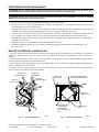
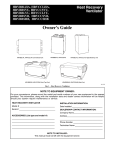
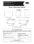
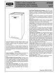
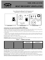
VA3B, VA5B, and VC5B
HEAT RECOVERY VENTILATOR
User’s Information Manual for the Operation and
Maintenance of Heat Recovery Ventilators
70
80
MODE
60
AIR EXCHANGE
´
ECHANGE
D´AIR
ON
MARCHE
50
OFF LOW HIGH
40
AIR EXCHANGE
´
ECHANGE
D´AIR
30
20
25
´ RELATIVE HUMIDITY
% D´ HUMIDITE
ARRET
50
OFF
LOW
ARRET
BASSE
INTERMITTENT
BASSE HAUTE
60
70
% HUM. RELATIVE HUM.
55%
45%
35%
30%
EXT. TEMP. EXT.
10°C/50°F
0°C/32°F
–10°C/14°F
–20°C/–4°F
80
MAINTENANCE
% HUM. RELATIVE HUM.
55%
45%
35%
30
30%
40
EXT. TEMP. EXT.
10°C/50°F
0°C/32°F
–10°C/14°F
–20°C/–4°F
25
20
´ RELATIVE HUMIDITY
% D´HUMIDITE
Basic Control
Standard Control
Automatic Control
Fig. 1 — Controls
A94244
OPERATING YOUR HEAT RECOVERY VENTILATOR (HRV)
Your HRV is designed to operate as an integral part of your total heating and cooling system. With the exception of high capacity
models, which are available with standard controls only, all HRVs offer 3 control options (See Fig. 1.):
• Basic Controls: Allow the user to manually set the unit to low- or high-fan speed as required to maximize comfort. Controls may
be unit mounted.
• Standard Controls: Offer automatic dehumidistat control and the option to select low speed or intermittent fan during heating season.
• Automatic Controls: In addition to the operational features found with standard controls, automatic controls feature a recirculation mode. Not for use with forced-air HVAC systems.
Fan Speed Control—Enables user to modulate fan speed from low to high.
Dehumidistat Control—Allows the user to select the relative humidity level at which the unit would change fan speed to avoid
condensation problems while heating during the winter months.
TABLE 1 — HUMIDITY SETTINGS
OUTSIDE TEMPERATURE
°C
°F
DOUBLE-PANE WINDOWS
TRIPLE-PANE WINDOWS
(PERCENTAGE)
(PERCENTAGE)
10
50
55
65
0
32
45
55
–10
14
35
45
–20
–24
30
40
–30
–22
25
35
Continuous Mode—If the relative humidity inside the building is lower than selected, air exchange would occur with the outside
at low speed. If the relative humidity level inside the building is higher than selected, air exchange would occur outside at high
speed. This ensures continuous air exchange for constant air quality.
Intermittent Mode—If the relative humidity inside the building is lower than selected, no air exchange would occur, and the system would turn off. If the relative humidity inside the building is higher than selected, air exchange would occur with outside at
high speed. This ensures minimum air exchange level when the building is unoccupied to minimize operating cost.
Recirculation Mode—If the relative humidity inside the building is lower than selected, indoor air would be circulated and filtered
at high speed. If the relative humidity inside the house is higher than selected, air exchange would occur with outside at high speed.
This ensures continuous movement and filtration of air for maximum comfort.
PERFORMING ROUTINE MAINTENANCE
! WARNING: Before servicing system, always turn off main power to system. There may be more than 1 disconnect switch.
Turn off accessory heater power if applicable. Electrical shock can cause personal injury or death.
! CAUTION: Although special care has been taken to minimize sharp edges in the construction of your unit, be extremely
careful when handling parts or reaching into the unit.
1. The motors are factory lubricated. Lubricating the bearings is not recommended.
2. The heat recovery core must be handled with care. To ensure maximum efficiency of the plastic partitions wash core once a
year following the season of most intense use.
Allow the heat recovery core to soak for 3 hr in a solution of warm water and mild soap. Rinse under a heavy stream of warm
water. Hot water and strong detergent should NOT be used, as it will damage the heat recovery core.
3. A dirty air filter will cause excessive strain on the blower motor. The filters in your HRV are washable, and should be cleaned
every 3 months. Use a vacuum cleaner to remove the heaviest portion of accumulated dust, then wash in warm water.
The maintenance light on the auto control will indicate when filters should be cleaned. The light will stay on until the door is
opened to service the unit.
4. Regularly check the screen on the exterior intake hood and clean as necessary.
5. Examine the condensate drain pan to ensure drains are functioning properly. Gently clean tray with mild soapy water.
(See Fig. 2 and 3.)
BEFORE YOU REQUEST A SERVICE CALL
• Check the main power disconnect switch. Verify that the circuit breakers are ON or that fuses have not blown. If you must reset
breakers or replace fuses, do so only once. Contact your servicing dealer for assistance if the breakers trip or the fuses blow a second time.
• Check for sufficient airflow. Check air filters for accumulations of large particles. Check for blocked exhaust-air grilles or ductwork. Keep grilles and ductwork open and unobstructed.
• If the condensate fails to drain properly, check the grommet and drain tube for obstructions. Make sure that the condensate drain
tube has a slight slope and is not kinked.
If your HRV still fails to operate properly, contact your servicing dealer. Give him your model and serial number. With this information, the dealer will be able to correct any problems.
FRESH AIR
FROM OUTSIDE
STALE AIR
TO OUTSIDE
FRESH AIR
TO BUILDING
STALE AIR
FROM BUILDING
FILTERS ARE REMOVABLE
BY PULLING STRAIGHT OUT
BRIEF CASE
TYPE LATCH
DOOR IS
DETACHABLE
HEAT RECOVERY
CORE CAN BE
REMOVED BY
PULLING STRAIGHT
OUT
CONDENSATE
DRAIN
A94263
A92382
Fig. 2 — Vertical Application
Copyright 1998 CARRIER Corp. • 7310 W. Morris St. • Indianapolis, IN 6231
Form: OMVA3B-1
Cancels: OG-VA3B-01
Printed in U.S.A.
Fig. 3 — Horizontal Application
7-98
Catalog No. 01VA-3B2