1
CCD Inspector and FWHM Monitor
Copyright © 2005-2007 by Paul Kanevsky
All Rights Reserved. Published by CCDWare under an exclusive license.
http://pk.darkhorizons.org
http://www.CCDWare.com
To purchase CCD Inspector: http://www.ccdware.com/buy
Check for product updates: http://www.ccdware.com/downloads/updates.cfm
CCD Inspector
Dramatically Improve quality of your images: increase sharpness and resolution
Automatically sort many images at once by evaluating star sharpness and tracking quality
Pick the best sub-frames for stacking, or for deciding which to keep
Compare images by many objective criteria, plot the results for a better visual impact
Measure and plot focus variations due to tilt or field curvature
Determine how flat the image plane is. Compare performance of field flatteners and focal reducers
Collimate your telescope in-focus with your CCD camera or DSLR!
Now works with CCDSoft, MaxIm DL, and all other camera control software in real-time mode
Focus and collimate your telescope using your favorite DSLR and DSLR control software!
Create running charts to monitor seeing conditions, focus shift, tracking problems with your CCD or DSLR in real-time
Astrophotograpers, CCD and digital camera users often take many shorter images to later process and stack to simulate one long
exposure. To produce the highest quality image, it is important to eliminate from the stack sub-frames that are of lower quality than
the rest. Sub-frames can be inferior due to changing focus, dew, tracking errors, flexure, mirror flop, wind, vibration, clouds, and
many other things.
With CCDInspector, you'll be able to quickly select the best frames of the batch by measuring the quality of each of the images.
The chosen images can be quickly moved or copied to a subfolder for stacking or further processing. CCDInspector works with
your camera acquisition software to allow real-time evaluation of images to determine collimation, image tilt, focus, etc.
CCDInspector can also be used independently of any capturing or processing software with all SBIG, FITS, TIFF, or DSLR
Raw formatted images on your computer. If your images are recorded with focal length information in the header, then multiple
images, even acquired with different focal length and aperture, can be compared by computing the FWHM value in arcseconds.
Release History
Version 1.3.2
Addresses variability in measurement results due to the use of DirectX3D. DirectX3D sets floating point calculation
accuracy to low for better performance, but this results in less precision in all calculations by CCDInspector. This has been
fixed.
Version 1.3.1
Fixed curvature display on the 3-D plot
Added automatic software update with periodic checks
Version 1.3.0
Full support of Windows Vista
Converted to .NET 2.0
Rewrite of the FWHM measurement algorithm to improve accuracy for undersampled images
Added Ignore button to warning messages
Added support for drag-and-drop of image lists to and from CCDStack
Added support for single-shot Bayer matrix CCD sensors
Added support for setting a custom saturation value
Fix for curvature % display: was incorrectly adjusted by image scale when displayed in arcseconds
Fix for X and Y tilt values in the Charts dialog (only Y was shown)
Fixed OK button placement in warning messages
Version 1.2.0
Fixed star selection algorithm that sometimes caused noise to be treated as stars
Added three Noise Threshold settings to improve star selection with noisy sensors (e.g., CMOS). The default, Low setting
should work well for most cooled CCD sensors.
Added "Measure selected images only" feature: if one or more images are selected in the list, only these will be measured
when Measure button is pressed. If none are selected, only new images in the list that have not been measured yet will be
measured.
Added Exposure, Bin Mode, and Temperature columns to the main image display and charts
Files that are loaded via AutoOpen option that are not in a recognizable format will now be quietly skipped and not
measured: no error message will be displayed
Version 1.1.10
Fixed TIFF file processing in FWHM Monitor
Improved filtered RGB image processing when most of the information is contained in one of the three channels
Added image date/time display for images that don't contain this information in the header (file creation date/time is now
shown)
Fixed the Measure All function bug that on occasion would still process some images that have already been measured
Version 1.1.9
Added support for ImagesPlus color FITS format (16-bit)
Measure All now measures only images that haven't been measured yet
Added AutoOpen feature to automatically measure any new image saved into specified folder
Version 1.1.7
Fixed: various errors and failures to measure with certain size images
Fixed: chart tilt X/Y were shown as the same value, and only in arcseconds
Improved star extraction algorithm: more stars are detected resulting in more accurate measurement
Improved algorithm for measuring undersampled stars: gives accurate result down to approximately 1.5 pixel FWHM
Version 1.1.3
Fixed failure to measure a large image or an image with a large number of stars
Collimation Viewer display no longer shows recommended correction to avoid setup confusion
Fixed the Curvature display in the main CCDInspector window column: the value originally displayed was incorrectly
adjusted by the image scale, and resulted in a number different from the one on the Curvature Map display
Version 1.1.1
Added user adjustable Top of Chip display to the Collimation Viewer to accommodate all camera positions on the back of
the telescope
Changed Collimation Viewer display to select only two of the three knobs for collimation to reduce risk of loosening the
secondary
Fixed the problem with reading TIFF files that was introduced with the addition of the RAW file support
Version 1.1.0
Intuitive Collimation Viewer added for fast and precise real-time collimation
Generic support for all image capture software, including AstroArt, MaxDSLR, etc., capable of writing FITS, TIFF, SBIG, or most native DSLR Raw file formats:
- For real-time curvature display and collimation, and
- For FWHM Monitor for focusing, focus monitoring, and running charts
Native support for over 100 DSLR RAW file formats - no conversion is needed into any other format
Support for color (RGB) FITS files in 16- and 8- bit formats as created by MaxIm DL
Added FITS header viewer
Air Mass index added to the calculated values
Stars Used is now displayed in the 2-D map viewer
Fixed a bug that caused problems copying and displaying large images
Star extraction algorithm tuned to find and use many more stars
Significantly improved collimation error computation improves stability and accuracy
Image list now shows Collimation and Tilt values in arcseconds or pixels, based on user selection
Support for OBJCTALT keyword for images captured in MaxIm DL
MaxIm DL image selection was improved for use with FWHM monitor: clicking on an image now activates it
Added Moving Average and Real-Time numeric display options to FWHM monitor to display the values from the current
running chart
Added the list of most-recently loaded images to the file menu
Version 1.0.0
Initial public release
Using CCDInspector
Start CCDInspector by double-clicking on the CCDInspector Panel icon on the desktop:
CCDInspector
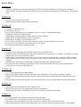
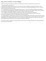
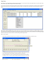
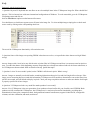
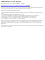
CCDInspector window will come up. The window is resizable, so you can expand it or collapse it to see more or less of the image data:
The display is designed to be as simple to use as possible. Here's a typical session with CCDInspector:
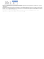
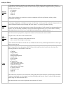
1. Click on the Open... button. A windows explorer will come up giving you the ability to select one or more images you'd like to measure:
Note that only files with Extensions of FIT, FTS, FITS, .S*, and .TIF* will be listed, as these are all the supported image types
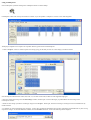
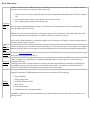
2. Select any number of the images from the Select Images window, and click Open. You'll see the images you picked added to the list of images in the
CCDInspector window:
3. If there are more images you'd like to sort through, simply click on the Open... button again, and select more images. The images list can be assembled from any
number of folders.
4. To measure raw, unprocessed images more accurately, you may chose to subtract a dark frame from each. This is particularly recommended with very faint or long
exposure raw images. To chose the dark frame reduction, click on the Reduce check box. You'll see the following window displayed:
Click on the Dark Frame button to browse for the appropriate dark frame file. Note that if you are measuring multiple exposures that of different exposure length, a
single dark frame will not work on all of them. In this case, it is better to not use image reduction.
Also, if the images you are measuring have already been dark-subtracted in another software package, uncheck the Reduce check box, as a second dark-subtraction
will be counter-productive.
5. Once you pick all the images, click on Measure All button and CCDInspector will go through the list of newly added images and measure each in turn. When
done, you'll see the results of the measurement next to each image name.
Any images that do not contain enough stars (or are too noisy to measure) will be listed with "N/A" in the FWHM and Aspect ratio columns. All other images will have
a number assigned to them representing their average FWHM and Aspect Ratio. If the images contain focal length information in their header, you can click the In
Arcseconds check box on, and the FWHM values will be shown in arcseconds, otherwise FWHM will be given in pixels.
6. Once measured, you can sort the images by any of the columns in the CCDInspector window, including FWHM and Aspect ratio, by simply clicking on the label in
the appropriate column. An up or down arrow will indicate what column is being sorted, and the direction of the sort (up means increasing values from top to bottom,
down means decreasing).
Note: there are many values that CCDInspector collects and measures for each image. You can chose to display all of them, or only the ones of interest to you by going
to the File/Settings/Display Columns menu, and then picking the columns you'd like to see.
7. At this point it is easy to see what images are better (for example, the ones with lower FWHM values, lower Aspect Ratio, and highest Contrast Ratio). You can
select a number of images to preview them before deciding to use them or not to use them. Simply highlight multiple images you want to see, and click on the Open
Selected button. The chosen images will come up in a number of Image Viewer windows floating above CCDInspector.
You can scroll around the image, and zoom in or zoom out by clicking anywhere in the image and picking the zoom level. As a shortcut, you can simply double-click on
any of the image names in the CCDInspector window to open it in the Image Viewer.
It is very easy to see the FWHM and Aspect Ratio values for any of the stars in the image: simply move the mouse pointer to point to the desired star, and a tool-tip
window will pop-up with the measured statistics for this star. If there's no star or the star cannot be properly measured (for example if it's too dim or oversaturated, or
bloomed), the tool-tip will display "N/A". Note that Image Viewer does not filter out hot pixels, as is done in the overall image Measurement step. This may result in
some hot pixels displaying an FWHM and Aspect value -- you should be able to tell where the real stars are. Hot pixels are ignored when determining the overall image
statistics.
8. When you decide on the set of images you'd like to use for stacking, you can select them in the CCDInspector window, and then click on Move To Folder or Copy
to Folder from the Images menu.
Move To Folder will physically move the images from their original folder to the folder of your choice. Copy To Folder will create a copy of all the chosen images,
keeping the originals intact.
9. You can also drag-and-drop files between CCDInspector and Windows Explorer or other applications. Files can be added by dragging them into CCDInspector.
Once measured and sorted, files can be moved or copied to the folder open in Windows Explorer by selecting and dragging them from CCDInspector to the Explorer
or other application window. Note that if you use just the mouse button to drag images, they will be moved (equivalent to Move Selected). If you'd like to copy the
files, leaving original images in the original folder, hold down the Ctrl key on the keyboard as you star the drag. This is the same way drag-and-drop works in
Windows Explorer to move files between folders.
HINT: Sometimes, you may want to move several files at once. If this is the case, hold down CTRL when you click on the file names. Each name will stay
highlighted as you select the next file. If all the files you wish to move are listed sequentially in a group, you can click on the first file, hold down the Shift
key and click on the last file. To move the selected documents, hold down the mouse button and drag to the desired destination. To copy, hold down the Ctrl
key as you start to drag. If you are having problems selecting multiple, please see FAQ item #1 below for a work-around.
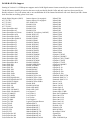
10. Once images are measured, it is easy to create a full report of the image names and their corresponding FWHM and Aspect Ratio values by clicking on the
File/Copy Report To Clipboard menu. The resulting report will be placed on the Windows Clipboard, and can be pasted into a text document, spreadsheet, e-mail,
etc. Here is an example of the report after being pasted into Microsoft Word:
File Path FWHM Aspect Ratio
C:\images\2005-08-24\VDB142_HA_20m.00000188.FIT N/A N/A%
C:\images\2005-08-24\VDB142_HA_20m.00000185.FIT 2.86 " 16%
C:\images\2005-08-24\VDB142_HA_20m.00000184.FIT 2.93 " 13%
C:\images\2005-08-24\VDB142_HA_20m.00000186.FIT 3.01 " 15%
C:\images\2005-08-24\VDB142_HA_20m.00000181.FIT 3.08 " 11%
C:\images\2005-08-24\VDB142_HA_20m.00000182.FIT 3.08 " 17%
C:\images\2005-08-24\VDB142_HA_20m.00000183.FIT 3.08 " 13%
C:\images\2005-08-24\VDB142_HA_20m.00000175.FIT 4.94 " 18%
C:\images\2005-08-24\VDB142_HA_20m.00000176.FIT 5.80 " 17%
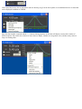
11. As a shortcut, you can do most of the operations listed above by simply clicking the right mouse button on the image list:
View will open all the selected images in Image Viewer
Remove will remove all the selected images from CCDInspector list
Add More Images... will allow to select more images for measurement
Move To Folder... will allow you to pick a folder to move the selected images to
Copy To Folder... will allow you to pick a folder to move the selected images to
Measure All will measure all the images in the list
Check All will select all items in the list
Uncheck All will unselect all items in the list
Curvature Map... will determine field curvature from selected images and display the map
3-D Curvature Plot... will use selected images to display the curvature in three dimensions
Charts... will allow you to see any of the measured values for all the images plotted against time, or any other image value
Installing CCD Inspector
To install CCD Inspector,
1. Download the installation file
2. Extract the files from the zip archive into a temporary folder
3. Double-click on the Setup.exe file to start the installation.
4. Follow prompts to select folders CCD Inspector. In most cases, accepting the default values will be sufficient.
5. On completing the install, double-click the CCD Inspector Panel icon on your desktop.
How does it work?
CCD Inspector employs a proprietary algorithm for star filtering and extraction. For each image, it will extract up to a few
thousand stars from the entire image, ignoring hot pixels and other non-stellar structures. As part of the analysis, CCD Inspector
will throw out stars that are bloomed or saturated, and any stars with too low a signal-to-noise ratio that may yield an inaccurate
measurement. It will then pick the median FWHM value, and the median Aspect Ratio value of all the stars remaining in the list.
These will be the values displayed next to the image name.
By its nature, the FWHM and Aspect Ratio displayed represent an "average" value for the image. There will be some stars with
higher and some with lower FWHM in the image. The same applies to aspect ratio value. The values chosen are meant to
quantify the image for a meaningful comparison between similar images, such as multiple sub-frames of the same field of view.
For images that contain some field curvature at the edges, the resulting measurement will not be skewed by such curvature, as long
as the majority of the stars are not on the periphery of the image.
What's in CCD Inspector?
CCDInspector is a collection of tools to help you get the best quality images from whatever optics and mount you currently use.
The two major tools are CCDInspector itself and a real-time FWHM Monitor utility. Both tools are integrated, but can be used
independently of each other.
The basic functions of each tool are as follows:
CCDInspector
1.
2.
3.
4.
5.
6.
7.
Measure and compare any number of saved images
Chose the best images by any measured criteria, move, copy, or drag selected images to other folders or applications
Plot values for all the images against any other value for a direct comparison
Preview any of the images, and determine FWHM and Aspect ratio of any star in the image by pointing to it
Analyze 2-D and 3-D curvature plots, determine image plane tilt, distance from perfect collimation, etc.
Monitor 2-D or 3-D curvature plots of images captured by the camera in real-time
Collimate your optics in real-time, in-focus, and with your CCD camera attached to the telescope FWHM Monitor
1.
2.
3.
4.
5.
6.
Focus your telescope by monitoring FWHM, HFD, Peak Value, or a number of other variable in real-time
Measure FWHM value for images as they are downloaded from the camera
Monitor focus over time by measuring FWHM of the autoguider star image
Monitor guiding or tracking accuracy by measuring star centroid wander
Monitor seeing conditions by measuring FWHM variations of a star in the focus window
Plot, on real time running chart, all the variables, such as FWHM, HFD, Peak Value, Aspect Ratio, Star Profile, Centroid
wander.
7. Select real-time or a moving average (or both) for the display, and choose how many points to keep on the running chart
Software Requirements
Operating systems currently supported are: Windows XP, Windows 2000, Windows 98.
Microsoft Direct X version 8.0 or later is necessary for 3-D graphics support
http://www.microsoft.com/directx/homeuser/downloads
Visual Basic 6.0 run-time environment is necessary to support real-time monitors when using CCDSoft:
http://www.microsoft.com/downloads/details.aspx?familyid=7b9ba261-7a9c-43e7-9117-f673077ffb3c&displaylang=en
Microsoft .NET Framework environment 2.0:
Microsoft .NET Framework runtime
Setting Image Scale
CCDInspector derives the information about image scale from the image header. The software used to acquire the image needs
to be set to record this information in the header, or it will not be available to CCDInspector.
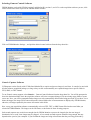
Setting up CCDSoft to record the focal length information in the image header:
In order to display information in arcseconds, you will also need to ensure that CCDSoft knows the focal length of your imaging
setup. For use with CCDInspector, this should be expressed in units of mm. This can be entered in CCDSoft in the Camera Setup
screen by pressing the File Defaults button:
Please make sure that the focal length is set in mm, and not inches, otherwise the arcseconds calculation will be incorrect.
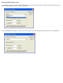
Setting up MaxIm DL to record the focal length information in the image header:
Click on File/Settings menu, and select Site and Optics tab, and enter the focal length and aperture parameters:
Note: If you select display in Arcseconds, but the focal length or pixel size parameters are not available from the image,
CCDInspector will display measurements in pixels by default.
CCD Inspector Display Elementsx
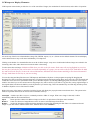
CCD Inspector main window provides the view of the sorted list of images, the mechanism for their selection, and a choice of operation:.
Across the top of the list are column headers (Image File, FWHM, Aspect (%), etc.). Shown are the default columns. The actual display
can be tailored to show any or all values calculated by CCD Inspector.
Clicking on the header of a column defines the sort order of all the images. An up arrow in the header indicates images are ordered in the
increasing value order, and a down arrow means the order is decreasing.
To select more than one image: hold down CTRL when you click on the file names. Each name will stay highlighted as you select
the next file. If all the files you wish to move are listed sequentially in a group, you can click on the first file, hold down the Shift
key and click on the last file. To move the selected documents, hold down the mouse button and drag to the desired destination. To copy, hold down the Ctrl key as you start to drag.
You can also drag-and-drop files between CCD Inspector and Windows Explorer or other programs accepting file dragging and
dropping. Files can be opened by dragging them into CCD Inspector and releasing (dropping) them on top of the list. Once measured and
sorted, files can be moved or copied to the folder open in Windows Explorer by selecting and dragging them from the list to the explorer
window. Note that if you use the mouse button to drag images, they will be moved. If you'd like to copy the files, leaving original images in
the original folder, hold down the Ctrl key on the keyboard as you star the drag. This is the standard way in which drag-and-drop works
in Windows Explorer to move files between folders.
Right click on any of the images or anywhere inside the list area will display the pop-up shortcuts menu shown above. The options in the
menu are equivalent shortcuts to the various menu commands at the top.
AutoOpen checkbox provides a way to to continually monitor a folder of images. When a new image is detected, it will be
automatically added to the list and measured
Open button provides a shortcut to add new images to the list. It is equivalent to File/Open menu command
Remove button is a shortcut to Images/Remove menu. It removes selected images from the list.
Reduce invokes the dark frame subtraction dialog that defines an image file containing the dark frame to be subtracted from all
images. If you don't want to subtract a dark frame, uncheck the box next to Reduce...
Note that if you are measuring multiple exposures that of different exposure length, a single dark frame will not work on all of them. In this
case, it is better to not use image reduction. Also, if the images you are measuring have already been dark-subtracted in another software
package, uncheck the Reduce check box, as a second dark-subtraction will be counter-productive.
In Arcsecs tells CCD Inspector that whenever possible the display should be in arcseconds instead of pixels. If image scale is not
available from the image, CCD Inspector will use the default image scale defined through Settings/Default Image Scale dialog. If that's also
not set, the values will be displayed in pixels.
Measure All will measure and display all the appropriate statistics for all the images in the list. You can interrupt the measurement
process by pressing and holding the Esc key until it stops. This option is available when no images are highlighted in the list.
Measure will measure only the selected images in the list. The selected images will be measured whether or not they have already been
measured previously.
Selected: the box below this label shows how many images are currently selected, and out of how many total images in the list.
View : shortcut to Images/View menu command: open selected images in the image viewer
Curvature shortcut to Analysis/Curvature Map menu command. Displays 2-D Curvature Map for all selected images
3-D Plot shortcut to Analysis/3-D Plot menu command
Charts shortcut to Analysis/Charts menu command
Using Image Viewer
Image Viewer (available from Images/View menu ) provides a quick preview of the image. This can be useful to confirm the measurements or to
verify that the image.
When an image is displayed in the Viewer, moving the mouse over any of the stars in the image will display the measurements associated with that
star in a pop-up window above the mouse cursor. Information displayed will contain the FWHM value, Aspect Ratio, and peak ADU value. N/A
will be displayed for any stars that CCD Inspector fails to measure (either because they are too large, distorted, too dim, not a stellar object, or
multiple stars too close to each other to distinguish). Note that Image Viewer does not filter out hot pixels, as is done during image measurement.
This may result in some hot pixels displaying an FWHM and Aspect value -- you should be able to tell where the real stars are. Hot pixels are
ignored when determining the overall image statistics.
You can scroll around the image, and zoom in or zoom out by clicking anywhere in the image and picking the zoom level. The following options are
available by clicking the right mouse button anywhere in the viewer window:
Use Zoom level to select the magnification level for the image display
Use Copy to Clipboard to place a copy of the image onto the Windows Clipboard. It can then be pasted into a document or into any image
editing software.
Display Range can be used to adjust the brightness levels for the image display, so as to show off more of the stars, or the object in the image
Use Next Image to display the next image in the list (in the order that they appear in the main CCD Inspector window)
Use Previous image to go back one image in the list
Start Animation will start an automatic display of all the images in sequence, in the order they appear in the main window
Stop Animation will stop the automatic display at the currently displayed image
Image Selection for Better Curvature Mapping
Ideally, the following criteria should be applied to the multiple image selection to produce an accurate curvature map:
1. All images must be of the same size
2. Images should be acquired during the same session with the same optical configuration, preferably with little or no focus
variations between the frames. The images do not have to be of the same area of the sky, but should be close-by to avoid the
effects of mirror-flop and flexure on focus.
3. Use CCDInspector to measure images, and pick only ones that are very close to each other in FWHM and Aspect Ratio.
4. Use images with a good sprinkling of unsaturated stars throughout the image frame. For example, a globular cluster would not
be a good image, as all the bright and bloated stars will be concentrated at the center of the glob.
5. Use CCDInspector dark frame reduction, or images that are already reduced by dark frame subtraction.
6. Use 3 or more consecutive images for building a more accurate curvature map. This increases signal-to-noise of the
measurement and produces a more accurate representation of the field curvature.
7. Use good sampling: if FWHM values are well below 2 pixels, the FWHM measurement will not be performed accurately, and
the resulting curvature map may appear distorted due to uncertainty in determining the correct stellar profile. One way to deal with
undersampled, short focal length configurations is to defocus the telescope slightly before taking a test image. This will result in
greater FWHM values that can then be more accurately measured by CCDInspector.
If you'd like to measure a single image, it should contain an evenly spread-out star field of unsaturated stars, and should be darkframe subtracted for best results.
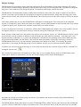
Using Curvature Map Viewer
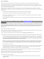
Curvature Map Viewer (available from Analysis/Curvature Map menu ) provides a topographic map of the image surface. Different colors are
assigned to various levels of focus: the darkest colors are best focus, the brightest colors -- the worst focus.
CCDInspector extracts thousands of stars from each image and computes their FWHM. Then, a polynomial function is fitted to the distribution of
FWHM values. This is then plotted using varying colors, as follows:
Black: lowest FWHM
Blue: slightly defocused
Green: more defocused
Red: highest defocus
Moving the mouse over any portion of the curvature map will display FWHM measurement associated with the stars in this area in a pop-up
window above the mouse cursor.
The top left corner contains a number of valuable statistics derived from the measured image:
Min FWHM: lowest FWHM value in the curvature map
Max FWHM: maximum FWHM value
Curvature: percent defocus between lowest and highest defocus points on the map
Tilt in X, Y: defocus from left to right, and from top to bottom of the image, expressed in arcseconds or pixels
Collimation: the distance between physical and optical centers in the image, shown in arcseconds or pixels. Assuming a small optical tilt, this
is how far the optics are from perfect collimation.
The two sets of crosshair in the middle of the image mark the physical (large circle) and optical (small circle) centers of the image. In a perfectly
collimated telescope, these will coincide. As much as a few arcseconds mis-collimation can affect image quality.
You can zoom in or zoom out by clicking anywhere in the image and picking the zoom level. The following options are also available by clicking the
right mouse button anywhere in the viewer window:
Use Zoom level to select the magnification level for the image display
Use Copy to Clipboard to place a copy of the map onto the Windows Clipboard. It can then be pasted into a document or into any image
editing software.
Display Range can be used to adjust the color assignment from lowest to highest FWHM values (the values in the range are always in pixels).
Use Next Image to compute and display the map for next image in the list (in the order that they appear in the main CCD Inspector window)
Use Previous image to go back one image in the list
Start Animation will start an automatic display of maps of all the images in sequence, in the order they appear in the main window
Stop Animation will stop the automatic display at the currently displayed image
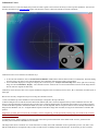
Using 3-D Curvature Plot Viewer
Just like the Curvature Map, the 3-D Curvature Plot provides a map of the image surface. The plot is shown in 3-Dimensions, with different colors
assigned to various levels of focus: the darkest colors are best focus, the brightest colors -- the worst focus.
CCDInspector extracts thousands of stars from each image and computes their FWHM. Then, a polynomial function is fitted to the distribution of
FWHM values. This is then plotted on a 3-D surface, with varying colors, as follows:
Black: lowest FWHM
Blue: slightly defocused
Green: more defocused
Red: highest defocus
Moving the mouse over any portion of the 3-D plot will display FWHM measurement associated with the stars in this area in a pop-up window
above the mouse cursor.
You can rotate, tilt and zoom in and out using the mouse in the 3-D view. To do this, click down on the left button anywhere in the 3-D view and:
Move mouse up and down to tilt back and forward
Move mouse left and right to rotate the image
Use the mouse track-wheel to zoom in and out, or hold down the Ctrl key on the keyboard and move the mouse up or down to zoom in or out.
The top left corner contains a number of valuable statistics derived from the measured image:
Min FWHM: lowest FWHM value in the curvature map
Max FWHM: maximum FWHM value
Curvature: percent defocus between lowest and highest defocus points on the map
The two axis are labeled X and Y near the bottom right corner of the image. X is the horizontal axis of the image.
You can zoom in or zoom out by clicking anywhere in the image and picking the zoom level. The following options are also available by clicking the
right mouse button anywhere in the viewer window:
Use Zoom level to select the magnification level for the image display
Use Copy to Clipboard to place a copy of the map onto the Windows Clipboard. It can then be pasted into a document or into any image
editing software.
Display Range can be used to adjust the color assignment from lowest to highest FWHM values (the values in the range are always in pixels).
Use Next Image to compute and display the map for next image in the list (in the order that they appear in the main CCD Inspector window)
Use Previous image to go back one image in the list
Start Animation will start an automatic display of maps of all the images in sequence, in the order they appear in the main window
Stop Animation will stop the automatic display at the currently displayed image
FITS Header Viewer
FITS Header Viewer is useful for verifying that the right image scale, focal length, camera settings, altitude, etc. are in the image
header. To display the viewer, select a single image from the list of all images, and click on the Images/View Image Header...
menu. This option is also available from the pop-up menu when right-clicking on any of the images in the list.
If any of the values are incorrect, you can use CCDSoft or MaxIm DL among other tools to correct them.
Precise Collimation
Unlike collimation procedures of the past, CCD Inspector provides a revolutionary new way to collimate a compound-optics telescope.
Collimation makes a huge difference in the quality of image and resolution that can be achieved. With CCDInspector, a collimation error of 10
arcseconds can produce as much as 1 arcseconds increase in FWHM of a star. This means that a good 3.0 arcsecond FWHM image can become
a 2.0 arcsecond image with proper collimation! By measuring the exact displacement of the optical center from the physical center of the imaging configuration, CCDInspector is capable of
detecting the smallest collimation errors with your CCD still attached to the telescope, and with telescope well focused! This is the best possible way
to collimate, since:
The optical train is not disturbed by removing an eyepiece and replacing the camera after collimation
Focus position will need only minor adjustments to get to best focus after collimation is completed
What's more, the collimation can occur right on, or very near-by to the field you will be imaging. This may be the best way to collimate a
telescopes with significant mirror flop
Since collimation is done on hundreds of stars, there's no need to re-center anything after adjusting collimation: just take the next image, and
keep adjusting.
[NOTE: Starting with Version 1.1.0 CCDInspector provides a simplified Collimation Viewer display that is even easier to use for realtime collimation]
To facilitate achieving perfect collimation, CCD Inspector provides two sets of crosshair on the screen: the larger one marking the physical center of
the chip, and the smaller one marking the current optical center of collimation. By making collimation adjustments to move the small crosshair to the
physical center of the chip, the best collimation is achieved. To help, CCD Inspector also provides a numeric reading at the top left of the Curvature
Map Viewer window that shows the distance between the two crosshair in arcseconds or pixels (based on the choice made in the main CCD
Inspector window).
The procedure to adjust collimation is fairly simple:
1. Find a reasonably crowded star field of reasonably evenly-spread stars, with no extremely bright stars in the field of view. Just point somewhere
near the Milky Way and you'll likely see many hundreds of stars in one shot.
2. Start CCD Inspector, and open the Real-Time Curvature Map window from Real-Time/Curvature Map... menu.
3. Start taking exposures using the camera's main chip. The following are some guidelines, actual settings will be different for each individual setup:
30 to 60 seconds exposure should be sufficient for best S/N and for collecting enough stars to measure field curvature. A longer exposure
may be necessary with really long focal length telescopes, or if a well-populated star field is not available. The goal is to see at least 100 or
more reasonably bright, but not saturated or bloomed, stars in the shot. More stars are better. A large concentrated star collection anywhere
in the image will distort the measurement (such as a globular cluster, for example).
Bin the chip 1x1 for best results with shorter focal length systems. FWHM of an average star in the field should be around 2 pixels or more.
If it's less, the FWHM measurement will not be as precise, resulting in a less sensitive curvature computation. If the seeing is exceptionally
good or the image is really undersampled, it would be desirable to defocus the image a bit to achieve the minimum of 2 pixels FWHM.
If your image scale is 0.6 arcsecs/pix
CCD Inspector will detect conditions when there aren't enough stars in the field of view, or they are not evenly spread out, and will display a
message indicating this may not result in an accurate measurement. If you receive this message, it's usually best to stop, and adjust the
parameters to get more stars in the field of view (increase exposure, or move the telescope).
4. After each exposure, check the curvature map to see how much, and in what direction to adjust collimation. Just like in standard collimation
techniques, the closer you get to perfect, the smaller the adjustments needed.
5. Make an adjustment, take the next image, and repeat with step 4. Keep doing this until the crosshair at the center overlap, and the error is
indicated as only a few arcseconds. At this point, you're in excellent collimation!
Some additional hints to help with collimation:
To help see the direction and distance of the collimation error, right click on the field curvature map. From the pop-up menu , select
Magnify Crosshair
You can also zoom-in further from the pop-up menu to see the error magnified. You may need to scroll the image to the center to see
the crosshair, if the zoomed-in image does not fit completely on the screen.
Remove as much tilt from the camera as possible to achieve best collimation. Use screw-in connectors exclusively, and if your focuser has
collimation adjustments, use them to square the camera to the optical train. You can use the CCD Inspector Tilt measurements in the realtime curvature map view to help with doing this.
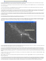
Make sure the telescope is cooled down and equalized with ambient air: if not, you will see strange artifacts in the curvature maps that are
due to air currents as the OTA cools, such as this:
Collimation Viewer
Collimation Viewer is a real-time display that provides an intuitive guide to the corrections necessary to achieve perfect collimation. This tool uses
the same calculation as the Curvature Map display, but shows the result in a form more suitable to real-time collimation:
Collimation Viewer can be started in two different ways:
To do real-time collimation, click on the Real-Time/Collimation Viewer menu from the main window in CCDInspector. Then start taking
exposures using your camera, and it will automatically show collimation from the most recently acquired image.
To see collimation display for an image, first display the curvature map for it: Analysis/Curvature Map menu. Then, right click on the map
image, and select Collimation Display... The Collimation Viewer will show the error and recommended correction for the image that was
used to create the original curvature map.
Collimation viewer shows the three-screw, tip-tilt collimation arrangement that is commonly used on SCT's, RC's, Newtonians, and other styles of
telescopes.
Here are the necessary configuration steps to start using the Collimation Viewer:
1. First, note that the top of the collimation viewer must always correspond to the top of the OTA
2. When looking at an SCT from the front, the three knobs, labeled A,B, and C need to be aligned to the top of the Collimation Viewer in the
same way the physical knobs are aligned to the top of the OTA. To align the display knobs, click the left mouse button on one of them, and drag
to rotate to the desired position. Note that the labels A, B, and C are not important, and are used just to make it easier to identify which button is
being selected. Whether A, B, or C is aligned with the top side in the above image does not matter, as long as one of the knobs is located in this
position.
Important: In order not to loosen the secondary mirror completely, avoid repeatedly turning any one knob in the counterclock-wise direction.
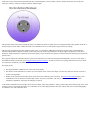
To collimate an SCT, start by looking at it from the front of the telescope towards the back. In the middle of the corrector, you'll find a the
secondary mirror with three collimation screws or knobs.
The image below shows a schematic view of the front of the secondary mirror with collimation screws represented by circles A, B, and C (note
that the actual labels are not important. They are there to make it easier to identify a knob on the telescope. If convenient, you can even add a
sticker next to each of the knobs to label them with the corresponding letter. This will make it easier to identify which knob to turn when the
telescope is rotated or when you are facing it from an difficult angle):
The top of the image will coincide with the top of the OTA and the top of the secondary mirror. To match the knobs to their position on the SCT ,
click and drag any of the A/B/C collimation knobs in the Collimation Viewer to rotate them to align with the top of image.
The same type of alignment procedure applies to an RC, MCT, or a Newtonian, although Newtonian may require a little experimentation to
determine which knob corresponds to the top of the image, since the camera is positioned at a 90 degree angle to the primary. For the RC or
Newtonian, simply imagine the Collimation Viewer knob display to show the back of the primary, with the three knobs controlling the tip-tilt of the
primary mirror.
Once properly aligned, the Collimation Viewer will show the collimation error direction and magnitude automatically, as soon as a new image is
downloaded from the camera using your configured image acquisition software. To make a correction, try turning each knob in turn to see which
one reduces the collimation error number displayed in the middle.
The display shows:
The magnitude of the collimation error in the center of the display
The direction of the collimation error shown by a line from the center of the viewer display. The line only shows the direction of the error,
not the error magnitude. Number of stars detected in the image (shown in the title of the Collimation Viewer window). The same recommendations apply to the
Collimation Viewer as do for the Curvature Map Viewer: 50 stars is a minimum, 100+ stars is recommended for a more accurate
collimation computation, and proper star sampling is required.
Note that the Collimation Viewer window can be sized to be better visible from a distance: simply click and drag on the bottom-right corner of the
window to increase or decrease the display size. Collimation viewer can be displayed at the same time with the real-time Curvature Map display
for a different view of the collimation error.
Using Charts
Charts feature is a powerful analytical tool that allows direct comparison of various measured values from multiple images. Any of the numeric values
can be used in a chart, whether computed or derived from the image.
To invoke charts, the images in the list must be measured, and CCD Inspector will prompt if this not already done. All images in the list are plotted on
the chart. Charts feature can be invoked through the Analysis/Charts menu or by clicking on the Charts button on the lower left panel of the main
window.
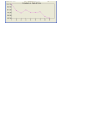
Charts default to displaying FWHM values over time. In this way, one can see the change in focus or tracking over a number of images. Any of the
numeric values can be selected for the horizontal axis, and any for the vertical. In this way, it's easy to find a correlation between different variables in
your system. Each point on the chart represents a single image and is marked by a small rectanle. If you move the mouse over the rectangle, a popup
window will show both, the values for X and Y axis for that image, and the image file name.
Here are some examples:
Aspect Ratio plotted against Altitude can give an indication of how the mount tracks depending on position in the sky:
Collimation plotted against altitude or time can give an indication of mirror flop in the system
X or Y tilt over time can be an indicator of focuser sag, flexure, or mirror flop
Background brightness over time can indicate the time of the night when the sky is darkest
Changing curvature over time also implies changing collimation due to flexure or mirror flop:
Using Generic Camera Control Software
CCDInspector works directly with CCDSoft and MaxIm DL to acquire and process images in real-time. Starting with version 1.1
it can also be used with all other software acquisition packages, as long as they are able to automatically save captured images
into a specific folder in FITS, SBIG, TIFF, or DSLR RAW formats.
To use the Generic camera support:
Select Settings/Camera Control Software/Generic... menu command. You will be prompted to chose the destination
folder where the acquisition software will write out captured images. Pick an existing empty folder or create a new one.
Select Real Time/Curvature Map... or Real Time/3D Curvature Plot menu to bring up the real-time viewer. You'll be
asked if you want to delete the images from the specified folder after measuring. Select Yes if you are not going to need the
images: CCDInspector will delete them automatically. Select No if you want to keep the images after they have been
measured by CCDInspector. CCDInspector will only inspect new files written to the folder, so you can keep older images
in the same folder.
Now, start the acquisition software, connect to the camera, point the telescope into a star-rich portion of the sky not far
from zenith, and set it to automatically save all the exposures to the same folder selected for CCDInspector Generic
analysis.
Next, start taking 10-30 second exposures. After each exposure is downloaded from the camera and saved into the
chosen folder, CCDInspector will pick it up, load and measure it, and display the corresponding curvature map.
If you chose Yes to delete the images, the image will be removed from this folder after the map is generated, otherwise, all images
captured by the camera will remain in this folder.
Do not use too short of an exposure. A short exposure is not very good for curvature analysis, and CCDInspector may not have
enough time to process the first image before the second one is downloaded. As a result, some images may be skipped. 10-30
seconds exposure should be long enough, but may depend on the speed of your computer.
.
DSLR RAW File Support
Starting in Version 1.0.1 CCDInspector supports native RAW digital camera formats created by the cameras shown below.
The RAW format capability is based on the source code provided by David Coffin, and only some have been tested by us.
David's software is very well written, and we are confident that all of the formats listed below will work. Should you find a format
that's listed but not working, please let us know.
Adobe Digital Negative (DNG)
AVT F-145C
AVT F-201C
AVT F-510C
AVT F-810C
Canon PowerShot 600
Canon PowerShot A5
Canon PowerShot A5 Zoom
Canon PowerShot A50
Canon PowerShot Pro70
Canon PowerShot Pro90 IS
Canon PowerShot G1
Canon PowerShot G2
Canon PowerShot G3
Canon PowerShot G5
Canon PowerShot G6
Canon PowerShot S30
Canon PowerShot S40
Canon PowerShot S45
Canon PowerShot S50
Canon PowerShot S60
Canon PowerShot S70
Canon PowerShot Pro1
Canon EOS D30
Canon EOS D60
Canon EOS 5D
Canon EOS 10D
Canon EOS 20D
Canon EOS 300D
Canon EOS 350D
Canon EOS Digital Rebel
Canon EOS Digital Rebel XT
Canon EOS Kiss Digital
Canon EOS D2000C
Canon EOS-1D
Canon EOS-1DS
Canon EOS-1D Mark II
Canon EOS-1Ds Mark II
Casio QV-2000UX
Casio QV-3000EX
Casio QV-3500EX
Casio QV-4000
Casio QV-5700
Casio QV-R51
Casio QV-R61
Casio EX-S100
Casio EX-Z50
Casio EX-Z55
Casio Exlim Pro 505
Casio Exlim Pro 600
Casio Exlim Pro 700
Imacon Ixpress 16-megapixel
Imacon Ixpress 22-megapixel
ISG 2020x1520
Kodak DC20
Kodak DC25
Kodak DC40
Kodak DC50
Kodak DC120 (also try kdc2tiff)
Kodak DCS315C
Kodak DCS330C
Kodak DCS420
Kodak DCS460
Kodak DCS460A
Kodak DCS520C
Kodak DCS560C
Kodak DCS620C
Kodak DCS620X
Kodak DCS660C
Kodak DCS660M
Kodak DCS720X
Kodak DCS760C
Kodak DCS760M
Kodak EOSDCS1
Kodak EOSDCS3B
Kodak NC2000F
Kodak ProBack
Kodak PB645C
Kodak PB645H
Kodak PB645M
Kodak DCS Pro 14n
Kodak DCS Pro 14nx
Kodak DCS Pro SLR/c
Kodak DCS Pro SLR/n
Kodak P850
Kodak KAI-0340
Konica KD-400Z
Konica KD-510Z
Leaf Aptus 17
Leaf Valeo 11
Leaf Valeo 22
Leaf Volare
Leica Digilux 2
Logitech Fotoman Pixtura
Minolta RD175
Minolta DiMAGE 5
Minolta DiMAGE 7
Minolta DiMAGE 7i
Minolta DiMAGE 7Hi
Minolta DiMAGE A1
Minolta DiMAGE A2
Minolta DiMAGE A200
Nikon E700
Nikon E800
Nikon E880
Nikon E900
Nikon E950
Nikon E990
Nikon E995
Nikon E2100
Nikon E2500
Nikon E3700
Nikon E4300
Nikon E4500
Nikon E5000
Nikon E5400
Nikon E5700
Nikon E8400
Nikon E8700
Nikon E8800
Olympus C5050Z
Olympus C5060WZ
Olympus C70Z,C7000Z
Olympus C740UZ
Olympus C770UZ
Olympus C8080WZ
Olympus E-1
Olympus E-10
Olympus E-20
Olympus E-300
Olympus E-500
Panasonic DMC-FZ30
Panasonic DMC-LC1
Panasonic DMC-LX1
Pentax *ist D
Pentax *ist DL
Pentax *ist DS
Pentax Optio S
Pentax Optio S4
Pentax Optio 33WR
Phase One LightPhase
Phase One H 10
Phase One H 20
Phase One H 25
Phase One P 20
Phase One P 25
Pixelink A782
Polaroid x530
Rollei d530flex
RoverShot 3320af
Sigma SD9
Sigma SD10
Sinar 12582980-byte
Contax N Digital
Creative PC-CAM 600
Epson R-D1
Foculus 531C
Fuji FinePix E550
Fuji FinePix F700
Fuji FinePix F710
Fuji FinePix F800
Fuji FinePix F810
Fuji FinePix S2Pro
Fuji FinePix S3Pro
Fuji FinePix S20Pro
Fuji FinePix S5000
Fuji FinePix S5100/S5500
Fuji FinePix S5200
Fuji FinePix S7000
Fuji FinePix S9000/S9500
Minolta DiMAGE G400
Minolta DiMAGE G500
Minolta DiMAGE G600
Minolta DiMAGE Z2
Minolta Alpha/Dynax/Maxxum 5D
Minolta Alpha/Dynax/Maxxum 7D
Nikon D1
Nikon D1H
Nikon D1X
Nikon D100
Nikon D2H
Nikon D2Hs
Nikon D2X
Nikon D50
Nikon D70
Nikon D70s
Sinar STI format
SMaL Ultra-Pocket 3
SMaL Ultra-Pocket 4
SMaL Ultra-Pocket 5
Sony DSC-F828
Sony DSC-R1
Sony DSC-V3
STV680 VGA
Definitions
A point source of light, such a star illuminates a number of pixels surrounding the center of the star. The center pixel is usually the
brightest, with the intensity of the pixels falling off rather rapidly the further away one looks from the center pixel. The faster the
light falls, the better the quality and sharpness of the star. The slower it falls, the more pixels the star occupies, the more bloated it
is, and therefore less focused. To come up with a standardized way to measure star quality, independent of the brightness and
magnitude of the star, the FWHM measure is used. FWHM stands for Full-Width at Half-Maximum and is simply the width (or
the diameter) of the circle surrounding the star where the intensity has fallen off by 50% from the peak value (half-maximum).
FWHM can be measured in pixels, or in arcseconds. Pixels is the default in CCDInspector if the focal length and the pixel size of
the camera cannot be determined. If these are known and specified in CCDSoft, CCDInspector can be used to automatically
convert pixels to arcseconds. The value in pixels is dependent on both, focal length and pixel size, and so cannot be used to
directly compare two images from different cameras, or from different telescopes. On the other hand, measurement in arcseconds
is independent from telescope focal length or the camera pixel size, and can be used for direct comparison between different
instruments.
Lower FWHM values are better -- means the star brightness falls off faster. There are many factors that limit just how low an
FWHM value one can get. Some of these are:
1. Focus: telescope must be well focused to produced lowest possible FWHM.
2..Collimation: poor collimation will lead to more bloated stars with higher FWHM
3. Seeing conditions: atmosphere is one of the major limiting factors even for professional astronomers. On a good day, an
average amateur with excellent optics and collimation can hope for FWHM of 2"-2.5". On rare occasions or at really great
locations, the seeing can dip to as low as 1.6" but not much below. More often than not, you're likely to see FWHM in the 3" to
4" range. Anything much above 4" is usually a signal to go inside and watch some TV -- the seeing is really poor.
4. Tracking and guiding: FWHM of a star in a long exposure can be much greater than FWHM of the same star in a really short
exposure. This happens because the air masses keep moving causing seeing fluctuations during long exposures, and guiders and
mounts usually have small errors that add up over a long period to smear the star a bit more.
Aspect Ratio: Aspect ratio represents how much out-of-round the star image is. It is the ratio of the longest axis to the shortest
axis of the star profile, expressed in percent. A number below 20-30% represents a pretty round star. A number of 0%
represents perfectly round star, but you will most likely not see this in real images due to noise and measurement uncertainty.
Image Header Keywords Used by CCDInspector
Keyword
Used In
Used For
FOCALLEN
CCDInspector, FWHM Monitor
Image scale determination
XPIXSZ
YPIXSZ
CCDInspector, FWHM Monitor
Image scale determination
PEDESTAL
CCDInspector, FWHM Monitor
To remove fixed pedestal from the image
EGAIN
E-GAIN
CCDInspector, FWHM Monitor
For reporting purposes
E_GAIN
DATE-OBS
CENTALT
OBJCTALT
CCD-TEMP
TEMPERAT
TEMPERATURE
EXPTIME
EXPOSURE
XBINNING
CCDXBIN
CCDInspector
Date and time of the exposure
CCDInspector
Altitude of the exposure
CCDInspector
Temperature of the sensor
CCDInspector
Image exposure length
CCDInspector
Image binning mode
FAQ
Frequently Asked Question (FAQ):
1. Question: My non-US keyboard does not allow me to select multiple items in the CCDInspector image list. What should I do?
Answer: This is a known issue with some international configurations of Windows. To work around this, go to the CCDInspector
File/Settings menu and click on the Use Checkboxes option near the bottom of the menu.
You should now see checkboxes appear next to all items in the image list. To select multiple images simply place a check mark
next to each by clicking on the corresponding check box:
The rest of the CCDInspector functionality will remain the same.
2. Question: Some of the images are reporting FWHM values that are too low, or Aspect Ratio values that are too high. What's
wrong?
Answer: Images with a lot of noise may fool the noise rejection filter in CCDInspector and force it to measure some hot pixels as
stars. To reduce the chance of this happening, measure images that have already been reduced with a d ark-frame subtraction, or let CCDInspector subtract a dark frame as described in step Quick Start topic..
3. Question: I select "In Arcseconds" option, but the FWHM is still shown in pixels. What's wrong?
Answer: Images are normally saved with headers containing information about pixel size and focal length of the telescope. If the
image you are measuring does not contain this information, CCDInspector will be unable to determine the conversion factor from
pixels to arcseconds, and will default to display in pixels. Check your image acquisition software to make sure that the focal length
is properly specified for all new images.
4. Question: "CCDInspector looks very much like another product I saw recently"
Answer: Yes! CCDInspector is the next generation of two products released earlier this year: StarSieve and CFWHM. Both
products are fully contained in CCDInspector, but CCDInspector is a major step forward in functionality, providing threedimensional curvature plots, comparison charts, background and contrast measurement, support for MaxIm DL, configurable
columns, real-time collimation, and much, much more!
File Menu
Select images for analysis and charting. Use the Files Type drop-down to select the type of images you are looking
for. SBIG, FITS, and TIFF format files are supported by CCDInspector. Multiple images can be selected at once.
Open
If you'd like to pick images from multiple folders, select images from first folder first and click Open. Then, click on
Open... menu again, change directory, and pick more files to add.
Select a folder of images to be measured and monitored in real-time. CCDInspector will load and measure all
existing images in the folder. What's more, it will continually monitor the folder for any new images. As soon as new
image(s) are added to the folder, these will automatically be added to the list and measured as well. This allows one
AutoOpen to monitor all downloads from a camera, and have them automatically measured as soon as they are saved by the
image capture software. The images can be in any of the formats supported by CCDI, including RAW.
To stop the automatic monitoring, click on AutoOpen again to uncheck it.
To pick a different folder, uncheck AutoOpen first, then check it again. When prompted, pick the new folder.
Copy
Measures the images, if they are not measured, and copies the result into a tabulated format onto Windows
Report to
Clipboard. This report can then be pasted into a document, spreadsheet, or a text file.
Clipboard
Exit
Quit CCD Inspector
Images Menu
View
View
Stars
Displays one or more selected images in their own Viewer windows.
Displays one or more selected images, placing circles around all the stars that were picked for FWHM measurement
and curvature analysis. These may not be all the stars in the image, as CCD Inspector rejects stars based on multiple
criteria: saturation, aspect ratio distortion, S/N, etc.
View
Image
Header
Displays a viewer with the list of all the keywords and values from the image header.
Remove
Remove selected images from CCD Inspector window. The actual image files are not affected by this operation.
Move to
Allows selected images to be moved to another folder. Image files will be physically moved from one folder to the
Folder
one specified.
Copy to
Folder
Allows selected images to be copied to another folder. Image files will remain in the original folder, and their copies
will be created in the one specified.
Check All Select all image files
Uncheck
All
Unselect all image files
Analysis Menu
CCD Inspector attempts to measure every image in the list. FWHM, Aspect ratio, and many other values are
computed. If any of the following columns are selected in the display, additional computation will be performed to
determine image curvature:
Measure
All
Curvature
Map
3-D
Curvature
Plot
Collimation
Curvature
Tilt in X
Tilt in Y
If none of these columns are selected, the curvature computation will not be performed, resulting in faster
measurement of all images.
Compute and display curvature map for the selected images. If more than one image is selected, all will be used in
the curvature computation, resulting in an average curvature map. In order to get best results, the images must be of
similar FWHM and similar exposure length, and of the same (or very near-by) portion of the sky.
For a proper curvature map, the image(s) must contain sufficient number of well-exposed, but not saturated stars to
measure. The stars should be reasonably evenly spread out through the field of view. For best results, avoid any
really bright objects in the field of view, such as galaxies, bright nebulae, or globular clusters.
Show the same information as presented in the Curvature Map, but in a 3 dimensional display. The 3-D Viewer
shows the curvature in perspective, and provides controls to rotate, tilt, and zoom in and out.
Using the mouse, click down on the left button and:
Move mouse up and down to tilt back and forward
Move mouse left and right to rotate image
Use the mouse track-wheel to zoom in and out, or hold down the Ctrl key on the keyboard and move mouse up or
down to zoom in or out.
Provides an analytical too to measure image quality based on a large number of measured values. Charts window
uses all images in the list as data points to plot. You have full control over the X and Y axis of the chart. The
following variables can be selected for either axis:
Charts
FWHM
Aspect Ratio
Air Mass Index
Background Brightness
Image Scale
Focal Length
Pixel Size
Camera Gain
Contrast to Noise Ratio
Total stars used in analysis
Altitude of the image
Date and time of the image
Curvature amount
Collimation error
Tilt in X
Tilt in Y
Chart window can be resized to see more details. Each point plotted on the chart has a small rectangle surround it.
If a mouse is positioned over the rectangle, a tool tip will display with both, the X and Y values for the data point,
and the image file name associated with it.
More than one chart viewer can be displayed at the same time, if desired..
Real-Time Menu
Creates a real-time viewer window to measure and display the curvature of every image as it is acquired from the
camera. To start real-time measurement, follow these steps:
Choose the correct camera acquisition software for you setup under the Settings menu (CCDSoft or MaxIm
DL)
If the camera control software is not already started, start it as usual
Start acquiring images using the main imager chip.
Curvature
Map
As each image is downloaded from the camera, CCD Inspector will automatically measure it and display the
curvature map based on its content.
With the cross-hair showing the difference between the optical center and physical center of the image, Real-Time
Curvature Map makes it easy and precise to collimate a telescope, without an eyepiece.
If the star field being imaged does not contain enough stars, CCD Inspector will display a warning message that the
curvature map may not be accurate.
3-D
Creates a real-time viewer window to measure and display 3-D plot of the curvature of every image as it is acquired
Curvature
from the camera. Follow the same steps to start the acquisition process as in the Curvature Map description above.
Map
Collimation Displays the Collimation Viewer window for real-time collimation. Follow the same directions to start collimating as
Viewer
in the section on Curvature Map above.
Select how many real-time images will be used to create each curvature or 3-D map. CCDInspector will wait for this
number of images to be captured before computing and displaying the curvature map. If 1 is selected, then no
Images to averaging will be done.
Average Averaging process allows a more accurate assessment of curvature and collimation to be made by including stars
from multiple exposures. Stars do not have to be aligned between frames: some shift is even desirable between
frames, as it will yield more information about the curvature of the entire image.
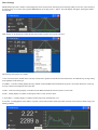
Displays the FWHM Monitor tool. This tool can also be invoked directly from the Desktop icon, or from the CCD
Inspector Start menu. FWHM Monitor provides real-time measurement of the following:
FWHM
Inspector
Image FWHM
Image Aspect ratio
Half-Flux Diameter (HFD)
Peak Value
Star Centroid Error
FWHM error due to seeing fluctuations
In addition, a number of real-time running charts are provided for display of all of these values in real-time or as a
moving average.
Settings
Set the default image scale, saturation level and monochrome/color options for all images where it cannot be
determined.
Default
Image
Properties
The image scale will be used in all cases where the arcseconds units are used for display, and the image
header does not contain either the focal length or pixel size keywords.
Saturation level sets the cut-off level, in ADU, beyond which a star will be considered saturated. Saturated
stars have distorted shapes, and their FWHM and star profiles cannot be accurately determined. For most
raw images from 16-bit CCD sensors, the default value of 45000 is a reasonable cut-off level and should
not need to be changed.
Sensor Type defaults to Monochrome. If you are using a single-shot color sensor with a Bayer matrix, select
Bayer Matrix instead. This will help CCDInspector to remove the effects of the Bayer filter matrix to more
accurately compute star profiles.
Chose the columns displayed in the main window of CCD Inspector. Once selected, any of the displayed columns
can be used to sort the image list in ascending or descending order of values for that column. The available choices
are shown below.
To select columns for display, highlight one or more column names in the list on the left (All Available Columns) and
click the >> button. To unselect a column, highlight it in the list on the right, and click << button. To rearrange the
order of columns, highlight a column in the Displayed Columns list, and use Move Up or Move Dn buttons to
reposition it. To restore the columns to default CCD Inspector settings, click the Default button.
Display
Columns
Air Mass index: specifies the amount of air the shot was made through, as compared to the amount of air
when shooting starlight at zenith. At zenith, the value for Air Mass is 1.0, and at Altitude 0 it is 40. Greater
value of Air Mass index indicates greater atmospheric distortion due to scatter, refraction, and seeing effects.
Altitude: this is the Alt coordinate of where the image was acquired, in degrees. This value is derived from
the image header
Bin Mode: binning mode of the detector that was used for this image
Aspect Ratio (%): the aspect ratio of an average star in the image. Aspect ratio number is a good
indication of how far out of round the stars are, possibly due to tracking errors or other distortions
Background (adu): Background brightness, in adu units. This represents an average background of the
image. This can be a good indication of how bright the sky was during the exposure
Collimation: error in collimation, expressed in arcseconds or pixels. Distance between optical and physical
centers at the image plane.
Contrast Ratio: actually, Contrast-to-Noise ratio. This is a good indicator of signal quality in the images
being compared. For example, amount of signal can be directly compared between images acquired through
different color filters. The higher the CNR, the more signal, and less noise and the darker the background in
the image.
Curvature: expressed in %: the amount of defocus between center and edge of the image, normalized to a
value that is independent of the actual FWHM values in the image. A good indication of how defocused the
stars are at the edge of the field compared to the center due to coma, spherical aberration, etc.
Date & Time: date and time of the exposure, as reported in the header of the image. This value is
converted to the local timezone configured on the computer.
Exposure: exposure length, in seconds
Focal Length (mm): focal length of the instrument used to acquire the image. This is derived from the image
header.
Folder: folder where the image file resides
Full Path: full path to the image, including the file name
FWHM: expressed in arcseconds or pixels. Average FWHM value derived from the image.
Gain (e-/adu): gain of the camera. Derived from image header.
Image File: name of the image file, without the folder
Pixel Size (um): pixel size of the camera, in microns. Derived from image header.
Scale ("/pix): image scale in arcseconds per pixel. Derived from image header focal length and pixel size
parameters, or, if not present, from the default image scale setting for CCD Inspector.
Stars Used: number of stars CCD Inspector used in measuring FWHM, Aspect Ratio, Curvature, etc. This
is not the actual number of stars in the image, as CCD Inspector can reject stars as unsuitable for
measurement due to saturation, low signal-to-noise ratio, or other distortions.
Temperature: sensor temperature used for this image
Tilt in X: the amount of defocus, in arcseconds or pixels, from left to right side of the image.
Tilt in Y: the amount of defocus, in arcseconds or pixels, from top to bottom of the image.
Chose the camera acquisition software that CCD Inspector will use with all the Real-Time monitors. The supported
software packages are:
Camera
Control
Software
CCDSoft from Software Bisque
MaxIm DL from Diffraction Limited
Generic image acquisition software
If you are not going to use real-time features of CCD Inspector, use the default setting of CCDSoft.
Generic support provides real-time support for any camera and acquisition software that allows FITS, SBIG, or
TIFF formatted images to be automatically written to a specified folder on the hard disk. As soon as an image is
captured, and saved to the selected folder, CCDInspector will automatically retrieve and analyze this image. You'll
have a choice of selecting whether the measured image is kept in the folder, or deleted after measurement.
Changes the main CCD Inspector window list to display check boxes next to each of the images. To select images
Use
for any operation will then require placing a check mark next to the desired image(s). This is necessary in some
Checkboxes
international versions of Windows, where the list control used in CCD Inspector does not allow multiple selection.
Sets the direction that the collimation screws move the mirror surface. Used by Collimation Viewer. The options
are:
Collimation
Screw
Direction
The default setting is appropriate for most commercial SCT's, RC's and Newtonian telescopes when collimating the
primary or the secondary mirrors. Changing this selection reverses the recommended direction to turn the
collimation screw in the Collimation Viewer.
Sets the noise threshold to use when selecting stars for measurement. The options are:
Noise
Threshold
Clock-Wise = Pull (Default)
Clock-Wise = Push
Low (default)
Medium
High
This setting allows for better star selection in some noisy sensors, such as CMOS-based, uncooled detectors. To
allow better discrimination between noise and stars for such sensors, set the Noise Threshold to Medium. If noise
is still selected as stars, increase the threshold to High.
For most CCD-based cooled sensors, the setting should be left at the default Low.
Help Menu
CCD
Inspector Displays this help file
Help
Set up automatic check for new software updates, or check for new updates right now. When a new update is
available, CCDInspector will inform you of this fact, and allow you to download and install the new version. Note
that if CCDInspector is already running, it will be closed before installation will begin:
Check for
Updates
Now! -- check if new updates are available right now. If they are, you'll be prompted to see if you want to
download and install them
Never -- disable automatic checks for new software releases
Every Time -- automatically check for new software releases every time CCDInspector is started
Once a Day -- automatically check for new software releases only the first time each day that CCDInspector
is started
Every 5 Days -- automatically check for new software releases every five days
Every 10 Days -- automatically check for new software releases every ten days
Every 30 Days -- automatically check for new software releases every thirty days
About
CCD
Inspector
Display the About box, with software version number and copyright notice.
FWHM Monitor for CCD Inspector Measure and Plot In Real-Time Any Star, Any Sub-Frame, Any Image:
FWHM, HFD, ASPECT RATIO, FLUX, CENTROID, PEAK VALUE and MORE!
FWHM Monitor is designed to work seamlessly with CCDSoft and MaxIm DL to provide these functions, along with a number
of other useful tools to estimate seeing, image quality, and tracking, and guiding performance.
FWHM Monitor can help perform the following functions:
1. Real-time focusing using Full-Width-at-Half-Maximum (FWHM), Peak Value, Half-Flux Diameter (HFD), and other display
statistics
2. Seeing conditions estimation by measuring FWHM or HFD of a star
3. Focus quality monitoring during a long exposure by measuring the quality of the star image on the autoguider chip
4. Fast and easy way to evaluate the quality of a long exposure containing multiple stars and extended objects
5. Measure FWHM or a number of other statistics of a specific star in the image by selecting it in CCDSoft
6. An easy and objective way to sort a number of exposures by sharpness.
There are many other uses. For example, the eccentricity measurement allows one to evaluate the coma distortion of a star near
the edge of the chip compared to the one in the center. The star profile plot allows one to see at a glance whether the star is
saturated, or has reached the non-linear region of the CCD chip, or has been distorted in some way by poor guiding or poorly
adjusted optics.
FWHM Monitor contains some very sophisticated algorithms to provide the most accurate measurement possible, while ignoring
spurious data, noise, and artifacts.
Using FWHM Monitor
FWHM Monitor application can be started or closed as needed. You don't have to shut down and restart CCDSoft or MaxIm
DL -- FWHM Monitor will automatically connect to the running instance of the configured application. The panel position, size
and selected options are remembered between sessions. If two instances of the Panel are started, only one will receive real-time
updates from the camera.
Double-click on the FWHM Monitor icon on the desktop to launch:
FWHM Monitor
The panel will float on top of your image acquisition software. If you will be focusing and standing far away from the monitor,
simply drag the bottom right corner of the panel window to increase its size. The text size will increase in proportion to the size of
the window. If desired, the panel can be stretched to occupy the size of the full screen.
The display panel is designed to be as simple to use as possible, and as easy to see in the dark and from a distance. If you would
like to see the profile plot of the star or a running real-time chart, click the expand button ">>" at the right :
There are some additional statistics shown below the profile plot: FWHM value, Aspect ratio, Peak value, and centroid
coordinates. Aspect ratio indicates how far out-of-round the star image is. For example, a star that's elongated due to tracking
error, or coma, will exhibit much higher aspect ratio. The ratio is expressed in %. A 9% out of round means that the longer axis of
the star is 1.09 times longer than the short axis. Usually a value below 30% or so is nearly invisible, but the elongation becomes
more obvious as the ratio increases.
The vertical line in the middle of the plot points to the location of the centroid. The coordinates of the center of the star, expressed
in CCD pixels, are shown in parenthesis at the right as (x,y).
You have a choice of display unit in FWHM Monitor: the values can be displayed in arcseconds or pixels. Simply place a check
mark next to In Arcsecs option if you'd like to see the display in arcseconds, and uncheck it to see it in pixels:
Click on the label next to the second number (the one showing Avg(3) in the above photo) to see additional choices of values that
can be displayed in addition to FWHM:
Once the chart window is opened with the ">>" button, clicking anywhere on the chart will display a menu with a number of
different options. These allow the selection of what values to display, whether to average them or not, and how many values to
keep on a running chart:
Selecting Camera Control Software
FWHM Monitor works with CCDSoft version 5 and MaxIm DL versions 3, and 4. To set the acquisition software you use, click
on the control menu at the top left of the FWHM monitor window:
Click on FWHM Monitor Settings..., and pick the desired control software from the drop-down list::
Generic Capture Software
CCDInspector works directly with CCDSoft and MaxIm DL to acquire and process images in real-time. It can also be used with
all other software acquisition packages, as long as they are able to automatically save captured images into a specific folder in
FITS, SBIG, or TIFF formats.
To use Generic camera support, select Generic... Camera Control Software from the drop-down list.. You will be prompted to
chose the destination folder where the acquisition software will write out captured images. Pick an existing empty folder or create
a new one. Next, you will be prompted whether images are to be automatically deleted after being processed. If you chose Yes to
delete the images, the image will be removed from the selected folder after its measurements are displayed by FWHM Montior,
otherwise, all images captured by the camera will remain in this folder.
Now, set up your acquisition software to automatically write out FITS, TIFF, or SBIG format files into the same folder you
selected in FWHM Monitor. The images can be full-frame, or sub-frame for faster focusing purposes.
Sub-second exposure may result in not enough time for FWHM Montior to process the image before the next image is
downloaded. As a result, some images may be skipped. A few seconds seconds exposure should be long enough, but may
depend on the speed of your computer. If you find that the images are being written faster than they are being processed by
FWHM Monitor, simply increase the exposure time, or add a small delay between the exposures in your capture software.
.
Selecting Default Image Scale
To set the default image scale to be used by FWHM monitor if the scale is not provded by the camera acquisition software, click
on the FWHM control menu at the top left of the window:
Click on FWHM Monitor Settings..., and enter the actual image scale for main imager and/or autoguider for your configuration:
Display Settings
FWHM Monitor has an automatic display mode that will measure the star immediately from an image captured by the camera.
You can choose to monitor images captured by either the main camera chip, or by the autoguider chip. To monitor the autoguider
chip, place a check mark next to the Autoguider option. To monitor the main imager, uncheck this option.
FWHM Monitor will automatically refresh its display and recalculate the values when a new image is captured. If you'd like to
measure a star from a specific image after it's already been captured (or loaded from disk), simply make this image active in the
camera control software, and click on the Get FWHM button. This will measure the currently active image in CCDSoft or MaxIm
DL.
If the image contains only one star, then FWHM Monitor will display its measurements. This works great for the autoguider
window, or in rapid focus mode with the sub-frame set to display one star. FWHM Monitor is smart, and will make every attempt
to ignore hot pixels, noise, airplane tracks, and other artifacts that are not stellar in nature.
In case of an image that is too noisy, or contains no valid star data, FWHM Monitor may display N/A or Not Available. This can
also happen if the star is very unfocused or extremely saturated, causing the FWHM value to exceed 30 pixels.
When an image contains many stars, and possibly other objects, such as nebulae, galaxies, etc., FWHM Monitor will pick a single
star to measure, based on a number of attributes. It will first isolate up to 1000 stars from the image. From these stars, it will
discard stars that are saturated, or very close to the background. It will then sort the remaining stars by their FWHM value and
will pick the median (middle) star from the list. This star will be most representative of the quality of the image. In this way,
FWHM Monitor allows a very easy and automatic measurement of the quality of any image. You can judge the guiding
performance of your mount, the changing seeing or focus conditions, and also sort your exposures based on sharpness.
In addition, you can select an area of the image, or even a single star that you'd like to measure using CCDSoft's or MaxIm DL's
rectangular selection tool: Once selected (the selected area can include one or many stars, or even extended objects), press Get FWHM button on the
display panel, and the best representative star from the selected rectangle will be measured and displayed.
Note that you can load a saved image at any time after it's been captured, and measure its quality using FWHM Monitor by
clicking on the Get FWHM button.
The FWHM Monitor display panel shows two values: FWHM and HFD by default. The top value will always show FWHM, but
you have a choice of what metric to display in the bottom value. Click your mouse directly on the label next to the lower number
display that contains the word HFD. You will see a pop-up menu with the following choices:
Click on the value you'd like to see displayed below the FWHM. See the Definition section for explanation of what each one of
these values measure. For example, here is a display with peak value option selected:
Note that the Peak Value display in FWHM Monitor is not exactly the same as the image maximum value: the peak value is the
maximum value of the selected star, not the whole image.
Chart Settings
FWHM Monitor provides a number of chart displays that can be useful in both, monitoring focus and image quality in real-time, and in measuring
an existing image. To view the chart, expand FWHM Monitor by clicking on the >> button. The Chart display will appear, showing the default
selected chart.
Chart settings can be changed by clicking the left mouse button anywhere on top of the chart area:
The following chart options are available:
1. Star X-Y Profile chart (default) shows currently measured star's profile in horizontal and vertical directions. Note that Moving Average setting
is not applicable to this chart type.
2. FWHM - a real-time running display showing a number of latest FWHM value measurements in pixels or arcseconds. Real-time, or Moving
Average or both can be displayed at the same time.
3. HFD - a real-time running display of a number of latest HFD measurements. Shown in pixels or arcseconds.
4. Peak - running display of a number of latest peak values of a star. Shown in ADU.
5. Aspect Ratio - a running display of a number of latest aspect ratio measurements, in %.
6. Centroid - a running display of the distance, in pixels or arcseconds, from the initial star position centroid. Can be used to evaluate seeing, and
tracking problems.
7. Seeing - is an RMS value of the FWHM variation. If taking really short exposures, this approximates the blurring effect of seeing, and can be
used to judge how good or bad the current atmospheric conditions are. Note that this does not measure the centroid wander resulting from bad
seeing, and so will usually underestimate the true FWHM value of seeing.
All charts except for the X-Y Profile can be used to display Real-time measurement, a Moving Average, or both by placing a checkmark next to
the appropriate menu selections.
For moving average selection, you have a choice of 2 points, 3, 4, 5, 6, 7, 8, 9, 10, or 20 points moving average.
The chart can also be set to display more or less points, as desired. To pick the number of points to keep on the chart, select Points on the
Chart menu, and pick the desired number (50,100,200,500, or 1000).
To restart the chart, and to reset the chart scale choose Clear Chart option. This will erase all historical data and will start measurements from
scratch.
If you'd like to pause the automatic chart refresh, click on the Pause Chart Updates option. The chart will not be updated until the check next to
the Pause Chart Updates option is removed.
FWHM Monitor will always show units next to the value. The following abbreviations are used: "
pix
a
a/p
%
(double quotation mark) stands for
arcseconds
stands for pixels
stands for ADU or analog to digital
units
stands for ADU/pixel and is used for
the average flux display
is used for the aspect ratio display
FWHM Monitor FAQ
Here are some common questions and answers:
1. "I selected display In Arcseconds option, but the display still shows values in pixels?"
Solution: Make sure you set the focal length in CCDSoft Camera File Defaults dialog or MaxIm DL Main Telescope Optical
Settings dialog.
2. "The FWHM or HFD display in arcseconds appears to be incorrect?"
Solution: Make sure to set the correct focal length (see #2 above) . If you are trying to measure an existing image, then you may
need to edit image header in CCDSoft or MaxIm DL, and verify that the FOCALLEN keyword is set to the correct focal length
in mm. To display image header information, select View\File Information... menu and click on the Edit Header tab in CCDSoft,
or View\Fits Header Window in MaxIm DL.
3. "It takes too long to display FWHM for a new image"
Solution: This may happen when trying to measure a large image with a lot of stars, or a lot of hot pixels. You can either use the
camera control software to select a small portion of the image with some representative stars to measure, use a sub-frame to
reduce image size, and/or use auto-dark frame subtraction to reduce noise.
4. "The display does not update when a new image is downloaded from the camera"
Solution #1: Check that the "Autoguider" option is set appropriately. If it's checked, and the camera is exposing images using the
main imager, no updates will be calculated since FWHM Monitor is waiting for an image from the autoguider.
Solution #2: If using CCDSoft, verify that the plugin is properly installed and enabled in CCDSoft. From the Camera Setup
screen, press Events Plug Ins button. If you don't see the "CCD Monitor Relay" event plug in, then it wasn't installed properly.
Try uninstalling FWHM Monitor from the Windows control panel Add/Remove software screen. Then, re-install FWHM
Monitor, making sure to provide the correct path to the CCDSoft folder.
5. I did a plate solve to get the exact image scale, but I don't know my effective focal length. What do I do?
FWHM Monitor will use image scale as computed by a plate solution, if available. Focal length doesn't need to be set in this case.
But, if you want to compute the focal length from a "solved" image scale, here is the formula you can use:
FocalLength = pixelsize * 206.2648 / imagescale
where FocalLength is the effective focal length expressed in millimeters, pixelsize is the size of the CCD pixel in microns, and
imagescale is the image scale as computed by the astrometric solution, in arcseconds/pixel.
7. What are the upper and lower limits on star size and image scale?
FWHM Monitor uses advanced interpolation and curve fitting techniques to measure star FWHM, even for very tiny stars. There
is a limit, though, to how small a star image can be before it becomes impossible to measure. For FWHM Monitor that limit is 1.3
pixels FWHM. In other words, if the star size is at or below 1.3 pixels, FWHM Monitor will be unable to measure it. This is
because the star spans a radius of less than two pixels, and therefore, there is just not enough information in the image to properly
measure its size.
At the other extreme, if FWHM value of an object exceeds 30 pixels, FWHM Monitor will give up on trying to measure it. This is
an arbitrary choice, made mostly to help FWHM Monitor not get bogged down in trying to measure large objects that are not
stellar in nature (such as the core of a galaxy, for example, or an extremely bloated and saturated star).