1
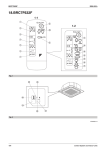
00_CV_3P107422-10S_1.fm Page 1 Thursday, June 5, 2008 2:23 PM OPERATION MANUAL Wireless Remote Controller Kit MODELS: BRC7E618 BRC7EA618 BRC7E619 BRC7EA619 English Deutsch Thank you for purchasing this Daikin air conditioner. Carefully read this operation manual before using the air conditioner. It will tell you how to use the unit properly and help you if any trouble occurs. After reading the manual, file it away for future reference. Vielen Dank für den Kauf einer Klimaanlage von Daikin. Bitte lesen Sie diese Bedienungsanleitung vor der Inbetriebnahme des Gerätes gründlich durch. Hier wird erklärt, wie das Gerät richtig eingesetzt wird und was bei Störungen zu tun ist. In dieser Anleitung wird nur das Innenaggregat beschrieben. Verwenden Sie diese Anleitung zusammen mit der Bedienungsanleitung des Außenaggregats. Nach dem Lesen der Anleitung legen Sie diese griffbereit zum Nachschlagen auf. Nous vous remercions pour votre acquisition de ce climatiseur Daikin. Lisez attentivement ce manuel avant d’utiliser le climatiseur. Il vous expliquera comment vous servir correctement de l’appareil et vous guidera en cas de problème. Lorsque vous aurez lu le manuel, rangez-le afin de pouvoir vous y référer ultérieurement. Le agradecemos la compra de este acondicionador de aire Daikin. Lea cuidadosamente el manual de funcionamiento antes de utilizar el acondicionador de aire. Dicho manual le indicará cómo utilizar adecuadamente la máquina y le ayudará en caso de avería. Después de leer el manual, consérvelo para consultas futuras. Français Español Italiano ÅëëçíéêÜ Nederlands Portugues Ðóññêèé 00_CV_3P107422-10S_2.fm Page 1 Thursday, May 29, 2008 7:14 PM La ringraziamo di aver acquistato questo condizionatore d’aria Daikin. Leggere attentamente questo manuale prima di avviare il condizionatore. Ciò permetterà di usare correttamente l’unità e di ottenere un aiuto in caso di anomalia di funzionamento. Dopo aver letto il manuale, conservarlo in un luogo accessibile per una futura necessità. Σαò εuχαριστοýìε που αγορÜσατε τη συσκευÞ κλιìατισìοý. ÄιαβÜστε προσεκτικÜ αυτÝò τιò οδηγßεò χρÞσηò πριν να χρησιìοποιÞσετε τη συσκευÞ κλιìατισìοý. Θα σαò πουν πωò θα χρησιìοποιÞσετε σωστÜ τη ìονÜδα και θα σαò βοηθÞσουν αν εìφανιστοýν προβλÞìατα. Αφοý διαβÜσετε τιò οδηγßεò, ΒÜλτε τιò στσ αρχεßο σαò για ìελλοντικÞ αναφορÜ. Wij danken u voor de aankoop van deze Daikin airconditioner. Lees deze bedrijfshandleiding aandachtig door voordat u de airconditioner gebruikt. Het omvat uitleg over het correcte gebruik van de unit en biedt hulp in geval een storing mocht optreden. Gebruik deze handleding voor verdere raadpleging. Obrigado pela sua compra deste aparelho de ar condicionado Daikin. Leia com atenção este manual de operação antes de proceder à utilização do aparelho de ar condicionado. Este indicar-lhe-á como deverá utilizar a unidade correctamente e ajudá-lo-á no caso de surgir qualquer problema. Depois de ler o manual, guarde-o num local seguro a fim de o poder consultar caso venha a ser preciso. Спасибо за поêóпêó данноãо êондиционера фирмы Daikin. До начала работы с êондиционером внимательно изóчите данное рóêоводство по эêсплóатации. В нем излаãаются правила надлежащеãо пользования óстройством и приводятся реêомендации пользователю по поисêó и óстранению неисправностей. После изóчения рóêоводства сохраните еãо для обращений в бóдóщем. 00_CV_3P107422-10S_2.fm Page 2 Thursday, May 29, 2008 7:14 PM 1-1 1 ON OFF 8 1-2 3 H M L DOWN 10 C ON OFF UP 6 TEMP FAN H 4 M L TIME C hr. UP 9 2 11 FAN hr. DOWN 13 RESERVE CANCEL hr. 5 TIMER 12 MODE 15 hr. TEST 7 SWING 14 16 TEST TEST 17 1 COOL/HEAT CHANGEOVER REMOTE CONTROL SWITCH 20 21 24 19 25 18 23 1-3 [1] 2 22 00_CV_3P107422-10S_3.fm Page 13 Thursday, May 29, 2008 7:14 PM PRIOR TO USE This operation manual is exclusively for instructions on how to use the wireless remote controller. Read also the operation manual attached to the indoor unit for safe usage of the system and maintenance. VOR DER INBETRIEBNAHME Diese Betriebsanleitung enthält ausschließlich Anweisungen über den Gebrauch der drahtlosen Fernbedienung. Über die sichere Anwendung und Wartung des Systems, lesen Sie auch die dem lnnenaggregat beiliegende Bedienungsanleitung. AVANT LA MISE EN SERVICE Ce mode d’emploi ne concerne que les instructions d’utilisation de la télécommande sans câble. Lire également le mode d’emploi joint à l’unité intérieure pour une utilisation et un entretien du système en toute sécurité. ANTES DE LA UTILIZACIÓN Este manual de instrucciones contiene sólo las instrucciones para el uso del control remoto sin cables. Lea también el manual de instrucciones que viene con la unidad interior para un uso seguro del sistema y para su mantenimiento. PRIMA DELL’USO Il presente manuale d’uso fornisce esclusivamente istruzioni per l’uso del telecomando via radio. Per un uso sicuro del sistema e per la sua manutenzione leggere inoltre il manuale d’uso in dotazione all’unità interna. ΠΡΙΝ ΑΠΟ ΤΗ ΧΡΗΣΗ Αυτü το εγχειρßδιο λειτουργßαò περιÝχει ìüνο οδηγßεò για τη χρÞση του ασýρìατου τηλεχειριστηρßου. ÄιαβÜστε επßσηò το εγχειρßδιο λειτουργßαò που συνοδεýει την εσωτερικÞ ìονÜδα για την ασφαλÞ χρÞση του συστÞìατοò και για τη συντÞρηση. VOOR GEBRUIK Deze bedieningshandleiding is uitsluitend bedoeld voor gebruik tijdens de instructie over de werking van de afstandsbediening. Lees ook de bedieningshandleiding die werd meegeleverd bij de binnenunit voor een veilig gebruik van het systeem en het onderhoud ervan. ANTES DE UTILIZAR O presente manual de funcionamento destina-se exclusivamente para explicar o modo de utilização do controlo remoto sem fio. Leia igualmente o manual de funcionamento fornecido com a unidade interior para uma utilização e manutenção segura do sistema. ПОДГОТОВКА К ИСПОЛЬЗОВАНИЮ Данное рóêоводство по эêсплóатации посвящено исêлючительно инстрóêтированию работе с беспроводным óдаленным êонтроллером. Для безопасноãо использования и техничесêоãо обслóживания системы ознаêомьтесь таêже с рóêоводством по эêсплóатации, прилаãаемом ê êомнатномó блоêó. [2] 00_CV_3P107422-10S_4.fm Page 1 Friday, May 30, 2008 9:51 AM GB Disposal requirements Batteries supplied with the remote controller are marked with this symbol. This means that the batteries shall not be mixed with unsorted household waste. If a chemical symbol is printed beneath the symbol, this chemical symbol means that the battery contains a heavy metal above a certain concentration. Possible chemical symbols are: Pb: lead (>0.004%) Waste batteries must be treated at a specialized treatment facility for re-use. By ensuring waste batteries are disposed of correctly, you will help to prevent potential negative consequences for the environment and human health. D Vorschriften zur Entsorgung Die mit dem Remote Controller mitgelieferten Batterien tragen dieses Symbol. Das bedeutet, dass Batterien nicht mit unsortiertem Hausmüll entsorgt werden dürfen. Wenn unterhalb des Symbols ein Symbol für eine chemische Substanz aufgedruckt ist, weist dieses chemische Symbol darauf hin, dass die Batterie ein Schwermetall enthält in einer Konzentration, die über einem bestimmten Grenzwert liegt. Mögliche Chemikalien-Symbole: Pb: Blei (>0,004%) Leere Batterien müssen bei einer Recycling-Einrichtung einer besonderen Behandlung unterzogen werden. Indem Sie dafür sorgen, dass leere Batterien einer ordnungsgemäßen Entsorgung zugeführt werden, helfen Sie, potenzielle negative Folgen für die Umwelt und die Gesundheit von Menschen zu vermeiden. F Instructions d’élimination Les piles fournies avec le dispositif de régulation à distance sont marquées de ce symbole. Cela signifie que les piles ne seront pas mélangées à des ordures ménagères non triées. Si un symbole chimique est imprimé sous le symbole, cela signifie que les piles contiennent un métal lourd au-delà d’une certaine concentration. Symboles chimiques possibles Pb: plomb (>0,004%) Les piles à jeter doivent être traitées dans des installations de traitement spécifiques pour être recyclées. En s’assurant que les piles à jeter sont éliminées correctement, on contribue à éviter les conséquences potentiellement néfastes sur l’environnement et la santé. E Requisitos para la eliminación Las pilas suministradas con el control remoto vienen marcadas con este símbolo. Esto significa que las pilas no deben mezclarse con el resto de residuos domésticos no clasificados. Si las pilas presentan un símbolo químico impreso bajo el símbolo, este símbolo químico significa que las pilas contienen un metal pesado que se encuentra por encima de una determinada concentración. Estos son los posibles símbolos quimicos: Pb: plomo (>0,004%) Las pilas gastadas deben ser tratados en instalaciones especializadas para su reutilización. Al asegurarse de desechar las pilas de la forma correcta, está contribuyendo a evitar posibles consecuencias negativas para el entorno y para la salud de las personas. I Istruzioni per lo smaltimento Le batterie fornite con il telecomando sono contrassegnate da questo simbolo. Ciò significa che non possono essere smaltite insieme ai rifiuti domestici non differenziati. Se sotto il simbolo è stampato un simbolo chimico, ciò significa che la batteria contiene un metallo pesante superiore a una data concentrazione. I simboli chimici possibili sono: Pb: piombo (>0,004%) La batterie esaurite devono essere trattate presso un impianto di trattamento specializzato per il riutilizzo. Il corretto smaltimento delle batterie esaurite eviterà le possibili conseguenze negative all’ambiente e alla salute dell’uomo. GR ΠροϋποθÝσειò απüρριψηò Οι ìπαταρßεò που παρÝχονται ìε το τηλεχειριστÞριο φÝρουν αυτü το σýìβολο. Αυτü σηìαßνει üτι οι ìπαταρßεò πρÝπει να απορρßπτονται χωριστÜ απü τα οικιακÜ απορρßììατα. Αv κÜτω απü αυτü το σýìβολο αvαγρÜφεται Ývα χηìικü σýìβολο, αυτü σηìαßvει üτι η ìπαταρßα περιÝχει συγκÝντρωση κÜποιου βαρÝοò ìετÜλλου παραπÜνω απü ìια συγκεκριìÝvη τιìÞ. ΠιθαvÜ χηìικÜ σýìβολα εßναι τα: Pb: ìüλυβδοò (>0,004%) Οι Üδειεò ìπαταρßεò θα πρÝπει να υφßσταvται επεζεργασßα σε ειδικÝò εγκαταστÜσειò για την επανÜχρησÞ τουò. Φροvτßζοvταò για τη σωστÞ απüρριψη τωv ìπαταριþv, θα συìβÜλετε στηv αποφυγÞ τωv πιθαvþv αρvητικþv επιπτþσεωv στο περιβÜλλοv και την αvθρþπιvη υγεßα. NL Vereisten voor het opruimen De bij de afstandsbediening geleverde batterijen dragen dit symbool. Dit betekent dat u geen batterijen mag mengen met niet-gesorteerd huishoudelijk afval. Als onder het symbool een chemisch symbool staat, geeft dit chemische symbool aan dat de batterij meer dan een bepaalde concentratie van een zwaar metaal bevat. Mogelijke chemische symbolen: Pb: lood (>0,004%) Afvalbatterijen moeten bij een gespecialiseerd behandelingsbedrijf worden behandeld voor hergebruik. Door ervoor te zorgen dat afvalbatterijen op de correcte manier worden opgeruimd, helpt u potentiële negatieve gevolgen voor het milieu en de gezondheid te voorkomen. P Requisitos para a eliminação As pilhas fornecidas com o controlo remoto possuem este símbolo. Significa que as pilhas não devem ser misturadas com o lixo doméstico indiferenciado. Se estiver impresso algum símbolo químico sob este, tal significa que a pilha contém um metal pesado com uma concentração acima de um determinado valor. Possíveis símbolos de produtos químicos: Pb: chumbo (>0,004%) As pilhas gastas têm de ser processadas num centro de tratamento especializado, para posterior reutilização. Ao certificar-se de que as pilhas são eliminadas correctamente, está a contribuir para evitar potenciais consequências negativas para o ambiente epara a saúde humana. RUS Утилизация отходов Этим символом помечены батарейêи, входящие в êомплеêтацию пóльта дистанционноãо óправления. Это значит, что данные батарейêи не следóет смешивать с несортированным бытовым мóсором. Если под óêазанным символом нанесен символ химичесêоãо вещества, последний означает, что батарейêа содержит тяжелый метал свыше определенной êонцентрации. Моãóт быть нанесены следóющие символы химичесêих веществ: Pb: свинец (>0,004%) Отработанные батарейêи следóет сдавать на специальнóю перерабатывающóю станцию для óтилизации. Обеспечивая надлежащóю óтилизацию отработанных батарееê, вы способствóете предотвращению неãативных последствий для оêрóжающей среды и здоровья людей. 01_EN_3P107422-10S.fm Page 1 Saturday, May 31, 2008 7:02 PM CONTENTS ILLUSTRATION ...............................[1] PRIOR TO USE ...............................[2] 1 SAFETY PRECAUTIONS..................1 2 NAMES AND FUNCTIONS OF THE OPERATING SECTION ....................4 3 HANDLING FOR WIRELESS REMOTE CONTROLLER..................5 4 OPERATION RANGE........................6 5 OPERATION PROCEDURE .............7 6 NOT MALFUNCTION OF THE AIR CONDITIONER ........................12 7 HOW TO DIAGNOSE TROUBLE SPOTS ..........................12 1. SAFETY PRECAUTIONS To gain full advantage of the air conditioner’s functions and to avoid malfunction due to mishandling, we recommend that you read this instruction manual carefully before use. This air conditioner is classified under “appliances not accessible to the general public”. The precautions described herein are classified as WARNING and CAUTION. They both contain important information regarding safety. Be sure to observe all precautions without fail. WARNING ....... Failure to follow these instructions properly may result in personal injury or loss of life. CAUTION ........ Failure to observe these instructions properly may result in property damage or personal injury, which may be serious depending on the circumstances. 1 After reading, keep this manual in a convenient place so that you can refer to it whenever necessary. If the equipment is transferred to a new user, be sure also to hand over the manual. WARNING Be aware that prolonged, direct exposure to cool or warm air from the air conditioner, or to air that is too cool or too warm can be harmful to your physical condition and health. When the air conditioner is malfunctioning (giving off a burning odor, etc.) turn off power to the unit and contact your local dealer. Continued operation under such circumstances may result in a failure, electric shocks or fire hazards. Consult your local dealer to install your equipment. Doing the work yourself may result in water leakage, electric shocks or fire hazards. Consult your local dealer regarding modification, repair and maintenance of the air conditioner or the remote controller. Improper workmanship may result in water leakage, electric shocks or fire hazards. Do not place objects, including rods, your fingers, etc., in the air inlet or outlet. Injury may result due to contact with the air conditioner’s high-speed fan blades. Beware of fire in case of refrigerant leakage. If the air conditioner is not operating correctly, i.e. not generating cool or warm air, refrigerant leakage could be the cause. Consult your dealer for assistance. The refrigerant within the air conditioner is safe and normally does not leak. However, in the event of a leakage, contact with a naked burner, heater or cooker may result in generation of noxious gas. Do not longer use the air conditioner until a qualified service person confirms that the leakage has been repaired. English 01_EN_3P107422-10S.fm Page 2 Saturday, May 31, 2008 7:02 PM Consult your local dealer regarding what to do in case of refrigerant leakage. When the air conditioner is to be installed in a small room, it is necessary to take proper measures so that the amount of any leaked refrigerant does not exceed the concentration limit in the event of a leakage. Otherwise, this may lead to an accident due to oxygen depletion. Contact professional personnel about attachment of accessories and be sure to use only accessories specified by the manufacturer. If a defect results from your own workmanship, it may result in water leaks, electric shock or fire. Consult your local dealer regarding relocation and reinstallation of the air conditioner. Improper installation work may result in leakage, electric shocks or fire hazards. Be sure to use fuses with the correct ampere reading. Do not use improper fuses, copper or other wires as a substitute, as this may result in electric shock, fire, injury or damage to the unit. Be sure to install an earth leakage breaker. Failure to install an earth leakage breaker may result in electric shocks or fire. Be sure to earth the unit. Do not earth the unit to a utility pipe, lightning conductor or telephone earth lead. Imperfect earthing may result in electric shocks or fire. A high surge current from lightning or other sources may cause damage to the air conditioner. Consult the dealer if the air conditioner submerges owing to a natural disaster, such as a flood or typhoon. Do not operate the air conditioner in that case, or otherwise a malfunction, electric shock, or fire may result. Do not start or stop operating the air conditioner with the power supply breaker turned ON or OFF. Otherwise, fire or water leakage may result. Furthermore, the fan will rotate abruptly if power failure compensation is enabled, which may result in injury. English Do not use the product in the atmosphere contaminated with oil vapor, such as cooking oil or machine oil vapor. Oil vapor may cause crack damage, electric shocks, or fire. Do not use the product in places with excessive oily smoke, such as cooking rooms, or in places with flammable gas, corrosive gas, or metal dust. Using the product in such places may cause fire or product failures. Do not use flammable materials (e.g., hairspray or insecticide) near the product. Do not clean the product with organic solvents such as paint thinner. The use of organic solvents may cause crack damage to the product, electric shocks, or fire. Be sure to use a dedicated power supply for the air conditioner. The use of any other power supply may cause heat generation, fire, or product failures. CAUTION Do not use the air conditioner for purposes other than those for which it is intended. Do not use the air conditioner for cooling precision instruments, food, plants, animals or works of art as this may adversely affect the performance, quality and/or longevity of the object concerned. Do not remove the outdoor unit’s fan guard. The guard protects against the unit’s high speed fan, which may cause injury. Do not place objects that are susceptible to moisture directly beneath the indoor or outdoor units. Under certain conditions, condensation on the main unit or refrigerant pipes, air filter dirt or drain blockage may cause dripping, resulting in fouling or failure of the object concerned. To avoid oxygen depletion, ensure that the room is adequately ventilated if equipment such as a burner is used together with the air conditioner. 2 01_EN_3P107422-10S.fm Page 3 Saturday, May 31, 2008 7:02 PM After prolonged use, check the unit stand and its mounts for damage. If left in a damaged condition, the unit may fall and cause injury. Do not place flammable sprays or operate spray containers near the unit as this may result in fire. Before cleaning, be sure to stop unit operation, turn the breaker off or remove the power cord. Otherwise, an electric shock and injury may result. To avoid electric shocks, do not operate with wet hands. Do not place appliances that produce naked flames in places exposed to the air flow from the unit as this may impair combustion of the burner. Do not place heaters directly below the unit, as resulting heat can cause deformation. Do not allow a child to mount on the outdoor unit or avoid placing any object on it. Falling or tumbling may result in injury. Do not block air inlets nor outlets. Impaired air flow may result in insufficient performance or trouble. Be sure that children, plants or animals are not exposed directly to airflow from the unit, as adverse effects may ensue. Do not wash the air conditioner or the remote controller with water, as this may result in electric shocks or fire. Do not place water containers (flower vases, etc.) on the unit, as this may result in electric shocks or fire. Do not install the air conditioner at any place where there is a danger of flammable gas leakage. In the event of a gas leakage, build-up of gas near the air conditioner may result in fire hazards. Do not put flammable containers, such as spray cans, within 1 m from the blow-off mouth. The containers may explode because the warm air output of the indoor or outdoor unit will affect them. 3 The batteries must be removed from the appliance before it is scrapped and they are disposed of safely. Arrange the drain to ensure complete drainage. If proper drainage from the outdoor drain pipe does not occur during air conditioner operation, there could be a blockage due to dirt and debris build-up in the pipe. This may result in a water leakage from the indoor unit. Under these circumstances, stop air conditioner operation and consult your dealer for assistance. The appliance is not intended for use by unattended young children or infirm persons. Impairment of bodily functions and harm to health may result. Children should be supervised to ensure that they do not play with the unit or its remote controller. Accidental operation by a child may result in impairment of bodily functions and harm health. Do not let children play on or around the outdoor unit. If they touch the unit carelessly, injury may be caused. Consult your dealer regarding cleaning the inside of the air conditioner. Improper cleaning may cause breakage of plastic parts, water leakage and other damage as well as electric shocks. To avoid injury, do not touch the air inlet or aluminum fins of the unit. Do not place objects in direct proximity of the outdoor unit and do not let leaves and other debris accumulate around the unit. Leaves are a hotbed for small animals which can enter the unit. Once in the unit, such animals can cause malfunctions, smoke or fire when making contact with electrical parts. Never touch the internal parts of the controller. Do not remove the front panel. Touching certain internal parts will cause electric shocks and damage to the unit. Please consult your dealer about checking and adjustment of internal parts. English 01_EN_3P107422-10S.fm Page 4 Saturday, May 31, 2008 7:02 PM Do not leave the remote controller wherever there is a risk of wetting. If water gets into the remote controller there is a risk of electrical leakage and damage to electronic components. When using the wireless remote controller, do not put a strong light beam or install an inverter fluorescent lamp near the receiving section on the main unit. A malfunction may occur. Watch your steps at the time of air filter cleaning or inspection. High-place work is required, to which utmost attention must be paid. If the scaffold is unstable, you may fall or topple down, thus causing injury. 7 8 9 10 2. NAMES AND FUNCTIONS OF THE OPERATING SECTION (Fig. 1, 2) DISPLAY “ ” (SIGNAL TRANSMISSION) 1 This lights up when a signal is being transmitted. DISPLAY “ ” “ ” “ ”“ “ ” (OPERATION MODE) DISPLAY “ H M L C 12 13 ” 2 This display shows the current OPERATION MODE. For cooling only type, “ ” (Auto) and “ ” (Heating) are not installed. 3 11 ” (SET TEMPERATURE) 14 15 16 This display shows the set temperature. hr. DISPLAY “ hr. ” 4 (PROGRAMMED TIME) This display shows PROGRAMMED TIME of the system start or stop. 5 DISPLAY “ ” (AIR FLOW FLAP) Refer to page 9. 6 DISPLAY “ ”“ ” (FAN SPEED) The display shows the set fan speed. English 17 18 TEST ” DISPLAY “ (INSPECTION/ TEST OPERATION) When the INSPECTION/TEST OPERATION BUTTON is pressed, the display shows the system mode is in. ON/OFF BUTTON Press the button and the system will start. Press the button again and the system will stop. FAN SPEED CONTROL BUTTON Press this button to select the fan speed, HIGH or LOW, of your choice. TEMPERATURE SETTING BUTTON Use this button for SETTING TEMPERATURE (Operates with the front cover of the remote controller closed.) PROGRAMMING TIMER BUTTON Use this button for programming “START and/or STOP” time. (Operates with the front cover of the remote controller opened.) TIMER MODE START/STOP BUTTON Refer to page 9. TIMER RESERVE/CANCEL BUTTON Refer to page 10. AIR FLOW DIRECTION ADJUST BUTTON Refer to page 8. OPERATION MODE SELECTOR BUTTON Press this button to select OPERATION MODE. FILTER SIGN RESET BUTTON Refer to the section of MAINTENANCE in the operation manual attached to the indoor unit. INSPECTION/TEST OPERATION BUTTON This button is used only by qualified service persons for maintenance purposes. EMERGENCY OPERATION SWITCH This switch is readily used if the remote controller does not work. 4 01_EN_3P107422-10S.fm Page 5 Saturday, May 31, 2008 7:02 PM RECEIVER 19 This receives the signals from the remote controller. OPERATING INDICATOR LAMP (Red) 20 This lamp stays lit while the air conditioner runs. It flashes when the unit is in trouble. TIMER INDICATOR LAMP (Green) 21 This lamp stays lit while the timer is set. AIR FILTER CLEANING TIME INDICATOR LAMP (Red) 22 Lights up when it is time to clean the air filter. DEFROST LAMP (Orange) 23 Lights up when the defrosting operation has started. (For cooling only type this lamp does not turn on.) FAN/AIR CONDITIONING SELECTOR SWITCH 24 Set the switch to “ ” (FAN) for FAN and “ ” (A/C) for HEAT or COOL. COOL/HEAT CHANGEOVER SWITCH 25 Set the switch to “ COOL and “ ” (COOL) for ” (HEAT) for HEAT. NOTES • For the sake of explanation, all indications are shown on the display in Figure 1 contrary to actual running situations. • Fig. 1-2 shows the remote controller with the front cover opened. • Fig. 1-3 shows this remote controller can be used in conjunction with the one provided with the VRV system. • If the air filter cleaning time indicator lamp lights up, clean the air filter as explained in the operation manual provided with the indoor unit. After cleaning and reinstalling the air filter, press the filter sign reset button on the remote controller. The air filter cleaning time indicator lamp on the receiver will go out. • The Defrost Lamp will flash when the power is turned on. This is not a malfunction. 5 3. HANDLING FOR WIRELESS REMOTE CONTROLLER Precautions in handling remote controller Direct the transmitting part of the remote controller to the receiving part of the air conditioner. If something blocks the transmitting and receiving path of the indoor unit and the remote controller as curtains, it will not operate. 2 short beeps from the receiver indicates that the transmission is properly done. Transmitting distance is approximately 7 m. Do not drop or get it wet. It may be damaged. Never press the button of the remote controller with a hard, pointed object. The remote controller may be damaged. Installation site • It is possible that signals will not be received in rooms that have electronic fluorescent lighting. Please consult with the salesman before buying new fluorescent lights. • If the remote controller operated some other electrical apparatus, move that machine away or consult your dealer. Placing the remote controller in the remote controller holder Install the remote controller holder to a wall or a pillar with the attached screw. (Make sure it transmits) English 01_EN_3P107422-10S.fm Page 6 Saturday, May 31, 2008 7:02 PM IN THE CASE OF CENTRALIZED CONTROL SYSTEM Placing the remote controller Removing the remote controller Slide from above Pull it upward If the indoor unit is under centralized control, it is necessary to switch the remote controller’s setting. In this case, contact your DAIKIN dealer. 4. OPERATION RANGE VRV System See the operation manual provided with the air conditioner. Split System Remote controller holder How to put the dry batteries If the temperature or the humidity is beyond the following conditions, safety devices may work and the air conditioner may not operate, or sometimes, water may drop from the indoor unit. COOLING OUTDOOR UNIT (1) Remove the back cover of the remote controller to the direction pointed by the arrow mark. (2) Put the batteries Use two dry cell batteries (AAA.LR03 (alkaline)). Put dry batteries correctly to fit their (+) and (–). COOLING R71 ONLY RP71 TYPE HEAT PUMP TYPE RY71 RYP71 (3) Close the cover [°C] INDOOR TEMPERA- HUMIDTURE ITY D 20 to 35 B 80% or below W 14 to 25 B D 18 to 35 B 80% or below W 12 to 25 B HEATING When to change batteries Under normal use, batteries last about a year. However, change them whenever the indoor unit doesn’t respond or responds slowly to commands, or if the display becomes dark. [CAUTIONS] • Replace all batteries at the same time, do not use new and old batteries intermixed. • In case the remote controller is not used for a long time take out all batteries in order to prevent liquid leak of the battery. English D 21 to 46 B D – 5 to 46 B [°C] OUTDOOR UNIT HEAT PUMP TYPE OUTDOOR TEMPERATURE RY71 RYP71 INDOOR OUTDOOR TEMTEMPERATURE PERATURE D B 15 to 27 D B W B – 9 to 21 – 10 to 15 DB: Dry bulb temperature WB: Wet bulb temperature The setting temperature range of the remote controller is 16°C to 32°C. 6 01_EN_3P107422-10S.fm Page 7 Saturday, May 31, 2008 7:02 PM 5. OPERATION PROCEDURE Refer to figure 1 on page [1] • Operating procedure varies with heat pump type and cooling only type. Contact your Daikin dealer to confirm your system type. • To protect the unit, turn on the main power switch 6 hours before operation. • If the main power supply is turned off during operation, operation will restart automatically after the power turns back on again. COOLING, HEATING, AUTOMATIC, FAN, AND PROGRAM DRY OPERATION Operate in the following order. • AUTOMATIC OPERATION can be selected only by Heat pump split system or Heat recovery VRV system. • For cooling only type, “COOLING”, and “FAN” and “DRY”operation are able to select. 〈〈FOR SYSTEMS WITHOUT COOL/ HEAT CHANGEOVER REMOTE CONTROL SWITCH〉〉 MODE ” ” ” • In this operation mode, COOL/HEAT changeover is automatically conducted. 7 OPERATION lamp lights up or goes off and the system starts or stops OPERATION. NOTE • Do not turn OFF power immediately after the unit stops. Then, wait no less than 5 minutes. Water is leaking or there is something else wrong with the unit. 〈〈FOR SYSTEMS WITH COOL/HEAT CHANGEOVER REMOTE CONTROL SWITCH〉〉 OPERATION MODE SELECTOR (1) Select OPERATION MODE with the COOL/HEAT CHANGEOVER REMOTE CONTROL SWITCH as follows. Press OPERATION MODE SELECTOR button several times and select the OPERATION MODE of your choice as follows. FAN OPERATION.............................. “ DRY OPERATION ............................. “ ON/OFF Press ON/OFF button 1 OPERATION MODE SELECTOR COOLING OPERATION .................... “ HEATING OPERATION ..................... “ AUTOMATIC OPERATION ................ “ 2 ON OFF Refer to figure 1-1,3 on page [1] Refer to figure 1-1, 2 on page [1] 1 • The function of this program is to decrease the humidity in your room with the minimum temperature decrease. • Micro computer automatically determines TEMPERATURE and FAN SPEED. • This system does not go into operation if the room temperature is below 16°C. COOLING OPERATION..............“ ” HEATING OPERATION ...............“ ” FAN OPERATION........................“ ” DRY OPERATION .......................“ ” ” ” • See “FOR SYSTEM WITHOUT COOL/ HEAT CHANGEOVER REMOTE CONTROL SWITCH” for details on dry operation. English 01_EN_3P107422-10S.fm Page 8 Saturday, May 31, 2008 7:02 PM (2) Press OPERATION MODE SELECTOR button several times and select “ ” (This operation is only available during dry operation.) 2 For programming TEMPERATURE, FAN SPEED and AIR FLOW DIRECTION, follow the procedure shown below. DOWN ON OFF TEMPERATURE SETTING ON/OFF Press ON/OFF button OPERATION lamp lights up or goes off and the system starts or stops OPERATION. NOTE • Do not turn OFF power immediately after the unit stops. Then, wait no less than 5 minutes. Water is leaking or there is something else wrong with the unit. [EXPLANATION OF HEATING OPERATION] DEFROST OPERATION • As the frost on the coil of an outdoor unit increase, heating effect decreases and the system goes into DEFROST OPERATION. • The fan operation stops and the DEFROST lamp of the indoor unit goes on. After 6 to 8 minutes (maximum 10 minutes) of DEFROST OPERATION, the system returns to HEATING OPERATION. Heating capacity & Outdoor air temperature • Heating capacity drops as outdoor air temperature lowers. If feeling cold, use another heater at the same time as this air conditioner. • Hot air is circulated to warm the room. It will take some time from when the air conditioner is first started until the entire room becomes warm. The internal fan automatically turns at low speed until the air conditioner reaches a certain temperature on the inside. In this situation, all you can do is wait. • If hot air accumulates on the ceiling and feet are left feeling cold, it is recommended to use a circulator. For details, contact the place of purchase. English ADJUSTMENT UP Press TEMPERATURE SETTING button and program the setting temperature. UP DOWN Each time this button is pressed, setting temperature rises 1°C. Each time this button is pressed, setting temperature lowers 1°C. In case of automatic operation UP DOWN Each time this button is pressed, setting temperature shifts to “H” side. Each time this button is pressed, setting temperature shifts to “L” side. [°C] Setting temperature H M L 25 23 22 21 19 • The setting is impossible for fan operation. NOTE • The setting temperature range of the remote controller is 16°C to 32°C. FAN FAN SPEED CONTROL Press FAN SPEED CONTROL button. High or Low fan speed can be selected. The microchip may sometimes control the fan speed in order to protect the unit. SWING AIR FLOW DIRECTION ADJUST Press the AIR FLOW DIRECTION ADJUST button to select the air direction as shown below. 8 01_EN_3P107422-10S.fm Page 9 Saturday, May 31, 2008 7:02 PM DISPLAY appears and the air flow direction continuously varies. (Automatic swing setting) Press AIR FLOW DIRECTION ADJUST button to select the air direction of your choice. DISPLAY vanishes the air flow direction is fixed (Fixed air flow direction setting). Adjusting left/right air flow direction Angle the flaps to the left/ right from the knob, as wanted or as needed to air condition the room. NOTE • Stop flaps from swinging before trying to angle them. Working while the flaps are moving may get your fingers pinched. MOVEMENT OF THE AIR FLOW FLAP For the following conditions, micro computer controls the air flow direction so it may be different from the display. Operation mode Cooling • When operating continuously at downward air flow direction Operation conditions 9 Heating • When room temperature is higher than the set temperature • At defrost operation (The flaps blow horizontally to avoid blowing cold air directly on the occupants of the room.) NOTE • If you try cooling or programmed drying, while the flaps are facing downward, air flow direction may change unexpectedly. There is nothing wrong with the equipment. This serves to prevent dew formed on parts in the air discharge outlet from dripping. • Operation mode includes automatic operation. PROGRAM TIMER OPERATION Operate in the following order. • The timer is operated in the following two ways. Programming the stop time ( ) .... The system stops operating after the set time has elapsed. Programming the start time ( ) .... The system starts operating after the set time has elapsed. • The timer can be programmed a maximum of 72 hours. • The start and the stop time can be simultaneously programmed. 1 TIMER TIMER MODE START/ STOP Press the TIMER MODE START/STOP button several times and select the mode on the display. The display flashes. For setting the timer stop .... “ For setting the timer start .... “ 2 ” ” PROGRAMMING TIME UP DOWN Press the PROGRAMMING TIME button and set the time for stopping or starting the system. UP DOWN When this button is pressed, the time advances by 1 hour. When this button is pressed, the time goes backward by 1 hour. English 01_EN_3P107422-10S.fm Page 10 Saturday, May 31, 2008 7:02 PM RESERVE 3 TIMER RESERVE Outdoor unit Press the TIMER RESERVE button. The timer setting procedure ends. The display changes from flashing light to a constant light. CANCEL 4 Indoor unit TIMER CANCEL Press the TIMER OFF button to cancel programming. The display vanishes. For example. ON OFF TEMP TIME C UP FAN DOWN RESERVE CANCEL hr. TIMER hr. MODE When the timer is programmed to stop the system after 3 hours and start the system after 4 hours, the system will stop after 3 hours and then 1 hour later the system will start. One of these remote controllers needs to be designated as the master remote controller. For Heat recovery system When one BS unit is connected with several indoor units. Outdoor unit BS unit Indoor unit NOTE • After the timer is programmed, the display shows the remaining time. HOW TO SET MASTER REMOTE CONTROLLER (For VRV system) • When the system is installed as shown below, it is necessary to designate the master remote controller. For Heat pump system When one outdoor unit is connected with several indoor units. English One of these remote controllers needs to be designated as the master remote controller. • Only the master remote controller can select HEATING, COOLING or AUTOMATIC (only Heat recovery system) OPERATION. When the indoor unit with master remote controller is set to “COOL”, you can switch over operation mode between “FAN”, “DRY” and “COOL”. When the indoor unit with master remote controller is set to “HEAT”, you can switch over operation mode between “FAN” and “HEAT”. When the indoor unit with master remote controller is set to “FAN”, you cannot switch operation mode. 10 01_EN_3P107422-10S.fm Page 11 Saturday, May 31, 2008 7:02 PM When attempting settings than that consented above, a “peep” is emitted as a warning. Only with Heat recovery system, you can set the indoor unit to AUTOMATIC. Attempting to do so, a “peep” will be emitted as a warning. How to designate the master remote controller Operate in the following order. 1 MODE Continuously press the OPERATION MODE SELECTOR button for 4 seconds. The displays showing “ ” of all slave indoor unit connected to the same outdoor unit or BS unit flash. 2 MODE Press the OPERATION MODE SELECTOR button to the indoor unit that you wish to designate as the master remote controller. Then designation is completed. This indoor unit is designated as the master remote controller and the display showing “ ” vanishes. • To change settings, repeat steps 1 and 2 . EMERGENCY OPERATION When the remote controller does not work due to battery failure or the absence thereof, use this switch which is located beside the discharge grille on the main unit. When the remote controller does not work, but the battery low indicator on it is not lit, contact your dealer. [START] 1 To press the emergency operation switch. The machine runs in the previous mode. The system operates with the previously set air flow direction. 11 1 2 [STOP] 2 Press the EMERGENCY OPERATION switch again. PRECAUTIONS FOR GROUP CONTROL SYSTEM OR TWO REMOTE CONTROLLER CONTROL SYSTEM This system provides two other control systems beside individual control (one remote controller controls one indoor unit) system. Confirm the following if your unit is of the following control system type. Group control system One remote controller controls up to 16 indoor units. All indoor units are equally set. Two remote controller control system Two remote controllers control one indoor unit. (In case of group control system, one group of indoor units) The unit follows individual operation. NOTES • Cannot have two remote controller control system with only wireless remote controllers. (It will be a two remote controller control system having one wired and one wireless remote controllers.) • Under two remote controller control system, wireless remote controller cannot control timer operation. • Only the operating indicator lamp out of 3 other lamps on the indoor unit display functions. NOTE • Contact your Daikin dealer in case of changing the combination or setting of group control and two remote controller control systems. English 01_EN_3P107422-10S.fm Page 12 Saturday, May 31, 2008 7:02 PM 6. NOT MALFUNCTION OF THE AIR CONDITIONER TEST 1 The following symptoms do not indicate air conditioner malfunction Press the INSPECTION/TEST button to select the inspection mode “ ”. I. THE SYSTEM DOES NOT OPERATE • The system does not restart immediately after the ON/OFF button is pressed. If the OPERATION lamp lights, the system is in normal condition. It does not restart immediately because a safety device operates to prevent overload of the system. After 3 minutes, the system will turn on again automatically. • The system does not restart immediately when TEMPERATURE SETTING button is returned to the former position after pushing the button. It does not restart immediately because a safety device operates to prevent overload of the system. After 3 minutes, the system will turn on again automatically. • If the reception beep is rapidly repeated 3 times (It sounds only twice when operating normally.) Control is set to the optional controller for centralized control. • If the defrost lamp on the indoor unit’s display is lit when heating is started. This indication is to warn against cold air being blown from the unit. There is nothing wrong with the equipment. “ ” appears on display and blinks. “UNIT” lights up. 2 UP DOWN Press PROGRAMMING TIMER BUTTON and change the unit number. Press to change the unit number until the indoor unit beeps and perform the following operation according to the number of beeps. Number of beeps 3 short beeps .... Perform all steps from 3 to 6 . 1 short beep ...... Perform 3 and 6 steps 1 long beep........ Normal state 3 MODE Press OPERATION MODE SELECTOR BUTTON “ ” on the left-hand of the malfunction code blinks. 7. HOW TO DIAGNOSE TROUBLE SPOTS I. EMERGENCY STOP When the air conditioner stops in emergency, the run lamp on the indoor unit starts blinking. Take the following steps yourself to read the malfunction code that appears on the display. Contact your dealer with this code. It will help pinpoint the cause of the trouble, speeding up the repair. English 4 UP DOWN Press PROGRAMMING TIMER BUTTON and change the malfunction code. Press until the indoor unit beeps twice. 12 01_EN_3P107422-10S.fm Page 13 Saturday, May 31, 2008 7:02 PM 5 MODE Press OPERATION MODE SELECTOR BUTTON • Check if there are batteries in the remote controller. Place the batteries. • Check if the indoor unit number and wireless remote controller number are equal. “ ” on the right-hand of the malfunction code blinks. 6 UP DOWN Press PROGRAMMING TIMER BUTTON and change the malfunction code. Press until the indoor unit makes a long beep. The malfunction code is fixed when the indoor unit makes a long beep. 7 MODE Number Number Reset of the display Press OPERATION MODE SELECTOR BUTTON to get the display back to the normal state. ON OFF 24 6 TEMP TIME UP CODE FAN UNIT NO. DOWN 24 6 RESERVE CANCEL TIMER Operate the indoor unit with the remote controller of the same number. Signal transmitted from a remote controller of a different number cannot be accepted. (If the number is not mentioned, it is considered as “1”) 2. The system operates but it does not sufficiently cool or heat. • If the set temperature is not proper. • If the FAN SPEED is set to LOW SPEED. • If the air flow angle is not proper. MODE 35 7 SWING Contact the place of purchase in the following case. /TEST 1 II. IN CASE BESIDES EMERGENCY STOP 1. The unit does not operate at all. • Check if the receiver is exposed of sunlight or strong light. Keep receiver away from light. 13 WARNING When you detect a burning odor, shut OFF power immediately and contact the place of purchase. Using the equipment in anything but proper working condition can result in equipment damage, electric shock and/or fire. English 01_EN_3P107422-10S.fm Page 14 Saturday, May 31, 2008 7:02 PM [Trouble] The RUN lamp of the indoor unit is flashing and the unit does not work at all. Malfunction Code Unit No. which sensed trouble ON OFF TEMP TIME UP CODE FAN UNIT NO. DOWN RESERVE CANCEL TIMER MODE SWING /TEST INSPECTION display [Remedial action] Check the malfunction code (A1 - UF) on the remote controller and contact the place of purchase. (See page 12.) English 14 00_CV_3P107422-10S_1.fm Page 2 Thursday, June 5, 2008 2:23 PM 3P107422-10S EM01A186C (0807) HT FS