1
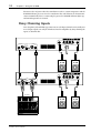
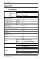
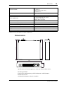
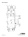
POWER AMPLIFIER
Owner’s Manual
POWER AMPLIFIER
L
20
POWER
TEMP
PROTECTION
POWER
ON
CLIP
R
15
20
25
LEVEL
30
6
3
40
OFF
L
0
Keep This Manual For Future Reference.
15
25
10
10
30
6
3
40
–dB
R
0
E
WARNING: THIS APPARATUS MUST BE EARTHED
IMPORTANT
THE WIRES IN THIS MAINS LEAD ARE COLOURED IN
ACCORDANCE WITH THE FOLLOWING CODE:
GREEN-AND-YELLOW :
EARTH
BLUE :
NEUTRAL
BROWN :
LIVE
As the colours of the wires in the mains lead of this apparatus may
not correspond with the coloured markings identifying the terminals in
your plug, proceed as follows:
The wire which is coloured GREEN and YELLOW must be
connected to the terminal in the plug which is marked by the letter E
or by the safety earth symbol
or coloured GREEN and YELLOW.
The wire which is coloured BLUE must be connected to the terminal
which is marked with the letter N or coloured BLACK.
The wire which is coloured BROWN must be connected to the
terminal which is marked with the letter L or coloured RED.
* This applies only to products distributed by YAMAHA KEMBLE
MUSIC (U.K.) LTD.
Important Information
i
Important Information
Please read the following before using the CP2000
Warnings
• Do not allow water to enter this unit or allow the unit to become wet. Fire or electrical
shock may result.
• Connect this unit’s power cord only to an AC outlet of the type stated in this Owner’s
Manual or as marked on the unit. Failure to do so is a fire and electrical shock hazard.
• Do not scratch, bend, twist, pull, or heat the power cord. A damaged power cord is a
fire and electrical shock hazard.
• Do not place heavy objects, including this unit, on top of the power cord. A damaged
power cord is a fire and electrical shock hazard. In particular, be careful not to place
heavy objects on a power cord covered by a carpet.
• Do not place a container with liquid or small metal objects on top of this unit. Liquid
or metal objects inside this unit are a fire and electrical shock hazard.
• If you notice any abnormality, such as smoke, odor, or noise, or if a foreign object or
liquid gets inside the unit, turn it off immediately. Remove the power cord from the AC
outlet. Consult your dealer for repair. Using the unit in this condition is a fire and electrical shock hazard.
• Should this unit be dropped or the cabinet be damaged, turn the power switch off,
remove the power plug from the AC outlet, and contact your dealer. If you continue
using the unit without heeding this instruction, fire or electrical shock may result.
• If the power cord is damaged (i.e., cut or a bare wire is exposed), ask your dealer for a
replacement. Using the unit with a damaged power cord is a fire and electrical shock hazard.
• Do not remove the unit’s cover. You could receive an electrical shock. If you think internal inspection, maintenance, or repair is necessary, contact your dealer.
• Do not modify the unit. Doing so is a fire and electrical shock hazard.
Cautions
• When rack-mounting the unit, allow enough free space around the unit for normal
ventilation. This should be: 10 cm behind, and 2 cm above.
For normal ventilation during use, remove the rear of the rack or open a ventilation hole.
If the airflow is not adequate, the unit will heat up inside and may cause a fire.
• This unit has ventilation holes at the front and rear to prevent the internal temperature
rising too high. Do not block them. Blocked ventilation holes are a fire hazard.
• Clean the contacts of the phone plug before connecting it to the SPEAKERS jack of this
unit. Dirty contacts may generate heat.
• Use only speaker cables when connecting speakers to amplifier outputs. Using other
types of cables is a fire hazard.
• Hold the power cord plug when disconnecting it from an AC outlet. Never pull the
cord. A damaged power cord is a potential fire and electrical shock hazard.
• Do not touch the power plug with wet hands. Doing so is a potential electrical shock
hazard.
• Do not use this amplifier for any purpose other than driving loudspeakers.
CP2000—Owner’s Manual
ii
Contents
Package Contents
The CP2000 package should contain the following items. Contact your Yamaha dealer
if anything is missing.
• CP2000 Power Amplifier
• This manual
Trademarks
Yamaha is a trademark of Yamaha Corporation. All other trademarks are the property
of their respective holders and are hereby acknowledged.
Copyright
No part of this Owner’s Manual may be reproduced or distributed in any form or by any
means without the prior written authorization of Yamaha Corporation.
© 2000 Yamaha Corporation. All rights reserved.
Contents
1
Introduction . . . . . . . . . . . . . . . . . . . . . . . . . . . . . . . . 1
Welcome . . . . . . . . . . . . . . . . . . . . . . . . . . . . . . . . . . . . . . . . . . . . . . . . . . . . . . . . . . . 1
Front Panel . . . . . . . . . . . . . . . . . . . . . . . . . . . . . . . . . . . . . . . . . . . . . . . . . . . . . . . . . 2
Rear Panel . . . . . . . . . . . . . . . . . . . . . . . . . . . . . . . . . . . . . . . . . . . . . . . . . . . . . . . . . . 3
2
Hookup Examples . . . . . . . . . . . . . . . . . . . . . . . . . . . . 4
Stereo Hookup . . . . . . . . . . . . . . . . . . . . . . . . . . . . . . . . . . . . . . . . . . . . . . . . . . . . . . 4
Parallel Hookup . . . . . . . . . . . . . . . . . . . . . . . . . . . . . . . . . . . . . . . . . . . . . . . . . . . . . 5
Bridge Mode Hookup . . . . . . . . . . . . . . . . . . . . . . . . . . . . . . . . . . . . . . . . . . . . . . . . 6
3
Using the CP2000 . . . . . . . . . . . . . . . . . . . . . . . . . . . . 7
Installation . . . . . . . . . . . . . . . . . . . . . . . . . . . . . . . . . . . . . . . . . . . . . . . . . . . . . . . . . 7
Connecting Inputs . . . . . . . . . . . . . . . . . . . . . . . . . . . . . . . . . . . . . . . . . . . . . . . . . . . 7
Connecting Speakers . . . . . . . . . . . . . . . . . . . . . . . . . . . . . . . . . . . . . . . . . . . . . . . . . 9
Connecting S115 and S112 loudspeakers . . . . . . . . . . . . . . . . . . . . . . . . . . . . . . . . 11
Turning On the Power . . . . . . . . . . . . . . . . . . . . . . . . . . . . . . . . . . . . . . . . . . . . . . . 11
Protection System . . . . . . . . . . . . . . . . . . . . . . . . . . . . . . . . . . . . . . . . . . . . . . . . . . . 11
Daisy Chaining Inputs . . . . . . . . . . . . . . . . . . . . . . . . . . . . . . . . . . . . . . . . . . . . . . . 12
Troubleshooting . . . . . . . . . . . . . . . . . . . . . . . . . . . . . . . . . . . . . . . . . . . . . . . . . . . . 13
Appendix . . . . . . . . . . . . . . . . . . . . . . . . . . . . . . . . . . . 14
Specifications . . . . . . . . . . . . . . . . . . . . . . . . . . . . . . . . . . . . . . . . . . . . . . . . . . . . . . . 14
Dimensions . . . . . . . . . . . . . . . . . . . . . . . . . . . . . . . . . . . . . . . . . . . . . . . . . . . . . . . . 15
Block Diagram . . . . . . . . . . . . . . . . . . . . . . . . . . . . . . . . . . . . . . . . . . . . . . . . . . . . . . 16
CP2000—Owner’s Manual
Introduction
1
1 Introduction
Welcome
Thank you for choosing the Yamaha CP2000 Power Amplifier. Based on a new
improved version of Yamaha’s EEEngine amplifier technology, the CP2000 is a versatile
two-channel power amplifier, offering high-power, superb sonic performance, and reliability, all backed by the Yamaha tradition of excellence in professional audio.
CP2000 key features include
• 650 W+650 W into 4Ω stereo, 450 W+450 W into 8Ω stereo.
• 2,000 W into 4Ω bridged, 1,300 W into 8Ω bridged.
• Yamaha Speaker Processing matches the CP2000 to the Yamaha S115 and S112 loudspeakers.
• Three operating modes are provided: STEREO mode in which Channel L and Channel
R operate independently, PARALLEL mode in which the channels operate independently but are both fed from the Channel L inputs, and BRIDGE mode in which both
channels are combined to form a massive 2000 watt single-channel amplifier.
• Improved EEEngine technology using MOSFET output devices.
• Compared to conventional designs, EEEngine’s energy saving capabilities reduce power
consumption by up to 50% and cut heat generation by up to 35%.
• Built-in limiter prevents excessive output signal distortion, protecting both speakers
and eardrums.
• Electronically balanced XLR-type and 1/4" phone jack input connectors.
• 5-way binding posts and 1/4" phone jack output connectors.
• Signal and CLIP indicators on each channel provide signal presence and clip warning.
• Relay-based protection system protects both amplifier and speakers if heatsink overheating occurs or a DC offset is detected at the outputs.
• TEMP indicator warns of heatsink overheating.
• Variable-speed low-noise fan regulates the system temperature even under the most
demanding conditions. While the CP2000 is idle, the fan stops for silent operation.
CP2000—Owner’s Manual
2
Chapter 1—Introduction
Front Panel
6
7
POWER AMPLIFIER
L
20
POWER
TEMP
ON
LEVEL
6
3
40
OFF
L
1 2 3 4
0
15
25
10
30
POWER
R
20
25
PROTECTION
CLIP
15
10
30
6
3
40
–dB
R
0
5
A POWER switch
This is the main POWER switch. Press to turn on the amplifier; press again to turn off.
See “Turning On the Power” on page 11 for more information.
B POWER indicator
This indicator lights up when the CP2000 is turned on.
C PROTECTION indicator
This indicator shows the status of the protection system. See “Protection System” on
page 11 for more information.
D TEMP indicator
This indicator lights up if the temperature of the CP2000’s heatsinks exceed 85 degrees
Celsius. Note that this indicator only serves as a warning. It does not indicate operation
of the protection system.
E Level controls
These controls are used to adjust the volume level of each channel. Since the gain of
each amplifier channel is fixed, these controls work by attenuating the input signal from
between –∞ dB and 0 dB. They are detented controls, which means they can be set to
any one of 31 positions. Detents protect against accidental adjustment, allow repeatable
setting, and make it easy to set both channels to the same volume. Usually these controls
are set to maximum and volume levels are controlled from the source equipment, typically a mixer.
F CLIP indicators
These indicators light up when a channel’s output signal distortion exceeds 1% (i.e.,
clipping). Output signal clipping is usually due to excessive input signal levels. If a channel’s output signal does clip, that channel’s limiter circuit is activated to prevent further
signal distortion. It’s okay for a CLIP indicator to light occasionally, but if it lights frequently, the LEVEL control should be turned down a little.
G LEVEL indicators
These indicators show the output signal level of each channel. The green indicators
light up when the output voltage is 2 V or greater, while the yellow indicators light up
when it’s 20 V or greater.
CP2000—Owner’s Manual
3
Rear Panel
Rear Panel
1
4
2
CHANNEL R
CHANNEL L
2
1
3
2
CHANNEL L
SPEAKERS
(BRIDGE)
STEREO
BRIDGE
PARALLEL
OFF
1
(–) BRIDGE (+)
INPUT
CHANNEL R
1
NEUTRIK
ON
2
1
3
YAMAHA
SPEAKER PROCESSING
2 3
5
A INPUTs
The inputs for each CP2000 channel comprise of one 1/4" phone jack and one
XLR-3-31-type connector. Both connectors are electronically balanced, although they
can also be used with unbalanced sources. See “Connecting Inputs” on page 7 for more
information. See also “Hookup Examples” on page 4.
Since the phone jack and XLR-type connector on each channel are internally connected, either connector can be used to distribute the input signal to another amplifier.
See “Daisy Chaining Inputs” on page 12 for more information.
B Mode switch
This switch is used to select the amplifier’s mode of operation: STEREO, PARALLEL,
or BRIDGE.
STEREO—In this mode, which is typically used to amplify stereo sources, the L and R
channels operate independently.
PARALLEL—In this mode, the L and R channels operate independently but the input
signal for both channels is sourced from the Channel L inputs. This mode is typically
used with a mono source and allows independent volume control of two sets of speakers.
BRIDGE—In this mode, the L and R channels are combined to form a massive 2000
watt single-channel amplifier. The input signal is sourced from the Channel L inputs,
the volume level is set by using the Channel L LEVEL control, and the speakers are connected to the binding posts labelled BRIDGE.
C YAMAHA SPEAKER PROCESSING switch
This switch is used to activate the special EQ processing that optimizes the CP2000 for
use with the Yamaha S115 and S112 loudspeakers. When other speakers are used, this
switch should be set to OFF. See “Connecting S115 and S112 loudspeakers” on page 11
for more information.
D SPEAKERS connectors
The outputs for each CP2000 channel comprise of one 1/4" phone jack and one pair of
5-way binding posts. The 1/4" phone jacks accept 1/4" phone plugs, while the 5-way
binding posts offer several methods of connection, including single or double banana
plugs, spade lugs, or bare wires. See “Connecting Speakers” on page 9 for more information. See also “Hookup Examples” on page 4.
CP2000—Owner’s Manual
4
Chapter 2—Hookup Examples
E GND terminal
For safety reasons it’s important that the CP2000 is grounded. The attached power cord
has a three-pin plug, and if the ground terminal of the AC outlet to which it is connected is grounded, then the CP2000 will be grounded adequately via the power cord.
If the AC outlet does not have a suitable ground terminal, a ground connection should
be made to this ground terminal. If hum or noise occurs, try to eliminate it by connecting this terminal to a good ground point or the chassis of the mixer, preamp, etc.
2 Hookup Examples
Stereo Hookup
In STEREO mode, the L and R channels operate independently. This mode is typically
used to amplify stereo sources. The following hookup example shows how the CP2000
can be used in STEREO mode.
STEREO
BRIDGE
PARALLEL
2
CHANNEL R
CHANNEL L
2
1
3
2
CHANNEL L
SPEAKERS
(BRIDGE)
STEREO
BRIDGE
PARALLEL
OFF
1
(–) BRIDGE (+)
INPUT
CHANNEL R
1
NEUTRIK
ON
2
1
3
YAMAHA
SPEAKER PROCESSING
or
ST OUT
Mixer
STEREO Notes:
• The stereo input source is connected to the L
and R inputs.
• The Channel L and Channel R volume levels
can be set independently.
• Speakers can be connected to the 1/4" phone
jacks and 5-way binding posts.
CP2000—Owner’s Manual
Total impedance:
2Ω min (1000 W)
4Ω (650 W)
8Ω (450 W)
Total impedance:
2Ω min (1000 W)
4Ω (650 W)
8Ω (450 W)
Parallel Hookup
5
Parallel Hookup
In PARALLEL mode, the L and R channels operate independently but the input signal
for both channels is sourced from the Channel L inputs. This mode is typically used
with a mono source and allows independent volume control of two sets of speakers.
The following hookup example shows how the CP2000 can be used in PARALLEL
mode.
STEREO
BRIDGE
PARALLEL
2
CHANNEL R
CHANNEL L
2
1
3
2
CHANNEL L
SPEAKERS
(BRIDGE)
STEREO
BRIDGE
PARALLEL
OFF
1
(–) BRIDGE (+)
INPUT
CHANNEL R
1
NEUTRIK
ON
2
1
3
YAMAHA
SPEAKER PROCESSING
Total impedance:
2Ω min (1000 W)
4Ω (650 W)
8Ω (450 W)
Total impedance:
2Ω min (1000 W)
4Ω (650 W)
8Ω (450 W)
MONO OUT
Mixer
PARALLEL Notes:
• The input source must be connected to the Channel L inputs.
• The Channel R inputs are inactive.
• The Channel L and Channel R volume levels can be set independently.
• Speakers can be connected to the 1/4" phone jacks and 5-way binding posts.
CP2000—Owner’s Manual
6
Chapter 2—Hookup Examples
Bridge Mode Hookup
In BRIDGE mode, the L and R channels are combined to form a massive 2000 watt single-channel amplifier. The input signal is sourced from the Channel L inputs. The following hookup example shows how the CP2000 can be used in BRIDGE mode.
STEREO
BRIDGE
PARALLEL
2
CHANNEL L
CHANNEL R
(BRIDGE)
2
1
3
STEREO
BRIDGE
PARALLEL
OFF
1
2
(–) BRIDGE (+)
INPUT
CHANNEL R
1
CHANNEL L
SPEAKERS
NEUTRIK
ON
2
1
3
YAMAHA
SPEAKER PROCESSING
Total impedance:
4Ω min (2000 W)
8Ω (1300 W)
MONO OUT
Mixer
BRIDGE Notes:
• The input source must be connected to the Channel L inputs.
• The volume level is set by using the Channel L LEVEL control.
• The Channel R inputs and LEVEL control are inactive.
• The speakers must be connected to the 5-way binding posts.
• The 1/4" phone jack outputs must not be used.
CP2000—Owner’s Manual
7
Using the CP2000
3 Using the CP2000
Installation
The CP2000 can be mounted in a standard rack and requires 2 rack-space units. In
addition to the front-panel rack-mounting holes, the CP2000 also features support
brackets at the rear, which offer additional support and should be fixed to the rear of
the rack. The CP2000 can also be placed horizontally on the floor or a suitable table.
The CP2000 uses a variable-speed low-noise fan to regulate the system temperature,
which draws air in from the front and expels it from the rear. For correct operation, it’s
important that the air flow at the front and rear of the CP2000 is not blocked or
restricted in any way. If the CP2000 is mounted in a portable rack with removable front
and rear covers, be sure to remove the covers before using the CP2000.
Connecting Inputs
Warning: Turn off all equipment before making any connections.
The inputs for each CP2000 channel comprise of one 1/4" phone jack and one
XLR-3-31-type connector. Both connectors are electronically balanced, although they
can also be used with unbalanced sources. For optimum performance, use only quality
screened cables for input connections. Under no circumstances should you connect
more than one sound source to the same channel. The inputs are designed to work with
line-level sources, such as mixers, CD players, and other professional audio equipment.
The 1/4" TRS (Tip-Ring-Sleeve) phone jacks are wired as follows: sleeve–ground,
tip–hot (+), and ring–cold (–).
TRS phone plugs should be wired as follows.
Tip (hot)
1/4" TRS phone plug
Ring (cold)
Sleeve (ground)
To connect an unbalanced source to an
INPUT jack, connect the ring (cold) terminal to the sleeve (ground) terminal, as
shown.
Tip (hot)
1/4" TRS phone plug
Ring (cold)
Sleeve (ground)
The XLR-type connectors are wired as follows: pin 1–ground, pin 2–hot (+), and pin
3–cold (–).
Male XLR plugs should be wired as follows.
Male XLR plug
1 (ground)
3 (cold)
2 (hot)
CP2000—Owner’s Manual
8
Chapter 3—Using the CP2000
To connect an unbalanced source to an
INPUT XLR, connect pin 3 (cold) to
pin 1 (ground), as shown below.
Male XLR plug
1 (ground)
3 (cold)
2 (hot)
The following table shows which inputs, LEVEL controls, and signal and CLIP indicators are active in each CP2000 mode.
Channel
R
L
CP2000—Owner’s Manual
Item
STEREO
PARALLEL
BRIDGE
INPUT connectors
O
X
X
LEVEL control
O
O
X
Signal & CLIP indicators
O
O
O
INPUT connectors
O
O
O
LEVEL control
O
O
O
Signal & CLIP indicators
O
O
O
9
Connecting Speakers
Connecting Speakers
Warning: Turn off all equipment before making any connections.
The outputs for each CP2000 channel comprise of one 1/4" phone jack and one pair of
5-way binding posts. The 1/4" phone jacks accept 1/4" phone plugs, while the 5-way
binding posts offer several methods of connection, including single or double banana
plugs, spade lugs, or bare wire.
For optimum performance, use quality
speaker cables with a suitable power rating.
Tip (+)
1/4" phone plug
Phone plugs should be wired as follows.
Sleeve (–)
When connecting to the binding posts, be
sure to connect the speaker cables with the correct polarity, otherwise, the sound quality will be affected. The plus (+) terminal on the speaker must be connected to the binding post labelled (+), and the (–) terminal on the speaker must be connected to the
binding post labelled (–).
Caution for Speaker Connection
Turn off the POWER switch.
2
Before connecting any speakers, remove the
protective cover by unscrewing the two fixing
screws shown here. Be sure to replace the
cover when you’ve finished making your connections.
3
When attaching bare-ended speaker cables,
strip off about 15 mm of insulation, unscrew
the binding posts, and insert the bare wires
through the holes in the posts, and then
tighten the binding posts. Make sure that none
of the bare wires are splayed in such a way that
they may cause a short.
Screw
1
15mm
1
1
When attaching speaker cables with spade lugs,
unscrew the binding posts, place the spade lugs on
the posts, and then tighten the binding posts.
4
Reattach the protective cover over the speaker
terminals.
European Specifications Only
This mark indicates a dangerous electri2
1
1
2
cally live terminal. When connecting an
external wire to this terminal, it is necessary
CHANNEL R
CHANNEL L
either to have “a person who have received
SPEAKERS
appropriate guidance on handling” make
the connection or to use leads or a cord that have been manufactured in such a way that
the connection can be made simply and without problem.
(—) BRIDGE (+)
CP2000—Owner’s Manual
10
Chapter 3—Using the CP2000
The following table shows which outputs can be used in each CP2000 mode and the
minimum speaker impedance. Note that this is the total speaker impedance that can be
connected to each channel. For example, a 2Ω minimum means that you could connect
a single 2Ω speaker, two 4Ω speakers in parallel, or four 8Ω speakers in parallel.
Mode
Item
STEREO
PARALLEL
Phone jack (2)
Channel R
X
2Ω min
Binding posts (1)
4Ω min
Binding posts (1)
Channel L
BRIDGE
2Ω min
Phone jack (2)
X
In the STEREO and PARALLEL modes, you can connect speakers to a channel’s 1/4"
phone jack and binding posts simultaneously, so long as the total impedance is not less
than 4Ω. In BRIDGE mode, the speakers must be connected to the binding posts
labeled “BRIDGE” and the 1/4" phone jacks cannot be used.
2
1
1
2
STEREO and PARALLEL
mode only
(–) BRIDGE (+)
CHANNEL R
CHANNEL L
SPEAKERS
4Ω min
4Ω min
(total 2Ω min)
4Ω min
4Ω min
(total 2Ω min)
When connecting speakers, it’s important that the total impedance is not less than the
minimum specified. In STEREO and PARALLEL modes, the minimum impedance is
2Ω, and for BRIDGE mode it’s 4Ω. When speakers are connected in parallel, the
impedance is reduced, as shown in the following examples. When connecting multiple
speaker cabinets, make sure the total impedance is not less than the minimum.
Total = 2Ω
Total = 4Ω
Total = 2Ω
8Ω
8Ω
4Ω
8Ω
8Ω
4Ω
8Ω
8Ω
See the “Hookup Examples” on page 4 for more information on connecting speakers.
CP2000—Owner’s Manual
11
Connecting S115 and S112 loudspeakers
Connecting S115 and S112 loudspeakers
The CP2000 features special EQ processing that optiOFF
ON
mizes the CP2000 for use with the Yamaha S115 and
S112 loudspeakers (especially the 115IV). This processYAMAHA
SPEAKER PROCESSING
ing is turned on and off by using the YAMAHA
SPEAKER PROCESSING switch. Yamaha loudspeakers
should be connected just like any other speaker, and for best performance the
YAMAHA SPEAKER PROCESSING switch should be set to ON. When using other
speakers, make sure the YAMAHA SPEAKER PROCESSING switch is set to OFF.
Turning On the Power
To prevent audible thumps and clicks, turn on your audio equipment in the
following order (reverse this order when turning off your equipment)—sound sources, mixer, CP2000.
1
POWER
Press the [POWER] switch to turn on the CP2000.
The CP2000 starts up and the POWER indicator lights up.
ON
OFF
The output relay closes, connecting the speakers, several seconds after the CP2000 is
turned on.
2
Press the [POWER] switch again to turn off the CP2000.
The POWER indicator goes out.
The output relay opens, disconnecting the speakers, immediately the CP2000 is turned off.
Protection System
The CP2000 features a relay-based protection system to protect
itself and the connected speakers against damage due to abnormal
operating conditions. When the protection system is active, the
speakers are disconnected from the CP2000 and the PROTECTION indicator lights up.
PROTECTION
When the CP2000 is turned on, the output relay remains open, disconnecting the
speakers, for approximately three seconds. During this time, the PROTECTION indicator lights up. When the protection system has confirmed that no abnormal conditions exist, the output relay closes, connecting the speakers, and the PROTECTION
indicator goes out. In addition to allowing the protection system to perform various
checks, protects the speakers against thumps and clicks as the CP2000 starts up.
When the CP2000 is turned off, the output relay opens immediately, disconnecting the
speakers, and preventing unwanted sound as the CP2000 shuts down.
If during normal operation the protection system detects that a heatsink has overheated
or a DC offset is present at a speaker output, the output relay opens, disconnecting the
speakers, and the PROTECTION indicator lights up. Once the heatsink has cooled
down, or the DC offset removed, the protection system automatically closes the output
relay, reconnecting the speakers, the PROTECTION indicator goes out, and normal
operation is resumed.
Heatsink overheating is typically caused by inadequate ventilation and it’s important
that you investigate the cause and resolve it (see page 13 for more information).
Another layer of protection is offered by the thermostatic cutout (auto-reset type) built
into the CP2000 power supply transformer. If abnormal operating conditions, such as
a shorted load or overload, continue for a long period of time, the thermostatic cutout
CP2000—Owner’s Manual
12
Chapter 3—Using the CP2000
disconnects the AC power when the transformer reaches a certain temperature and the
POWER indicator goes out. Once the transformer has cooled down, the thermostatic
cutout automatically closes, reconnecting the power, the POWER indicator lights up,
and normal operation is resumed.
Daisy Chaining Inputs
Since the phone jack and XLR-type connector on each input channel are internally connected, input signals can easily be distributed to other amplifiers by daisy chaining the
inputs, as shown below.
2
CHANNEL R
CHANNEL L
2
1
3
2
CHANNEL L
SPEAKERS
(BRIDGE)
STEREO
BRIDGE
PARALLEL
OFF
1
(–) BRIDGE (+)
INPUT
CHANNEL R
1
NEUTRIK
ON
2
1
3
YAMAHA
SPEAKER PROCESSING
2
CHANNEL L
(BRIDGE)
2
1
3
STEREO
BRIDGE
PARALLEL
OFF
NEUTRIK
ON
2
1
3
YAMAHA
SPEAKER PROCESSING
ST OUT
Mixer
CP2000—Owner’s Manual
1
(–) BRIDGE (+)
INPUT
CHANNEL R
1
CHANNEL R
CHANNEL L
SPEAKERS
2
Troubleshooting
13
Troubleshooting
The following table explains the operation of the CLIP, TEMP, and PROTECTION
indicators, typical situations in which they may light up, and what action to take if and
when they do.
Symptom
Remedy
Protection System
POWER indicator
not lit
Power cable disconnected or amplfier
turned off.
Make sure the power
cable is connected
properly and the
POWER switch is in
the ON position.
—
No sound
Input signal not connected or LEVEL controls turned down.
Check the input connections and LEVEL
control settings.
—
Stereo sources
sound odd
Incorrect speaker
polarity.
Check the polaity of
the speaker connections and correct if
necessary.
—
The input signal is too
high.
Reduce the input signal level, or turn
down the LEVEL control.
The speaker impedance is too low.
Ensure that the total
speaker impedance is
not less that 2Ω (STEREO/PARALLEL) or 4Ω
(BRIDGE).
There is a short at the
speaker terminals,
amplifier terminals, or
in the speaker cable.
Locate and remove
the short.
The heatsink temperature has exceeded
85˚C.
Make sure that the air
vents are not blocked
and improve the airflow around the
amplifier.
The heatsink temperature has exceeded
90˚C.
Make sure that the air
vents are not blocked
and improve the airflow around the
amplifier.
A DC offset of ±2 V or
more was detected at
the amplifier’s outputs.
Contact your Yamaha
dealer or service center.
CLIP indicator lit
TEMP indicator lit
PROTECTION
indicator lit
Possible Cause
The limiter circuit prevents further clipping
distortion.
The heatsink temperature warning circuit
activates.
The protection circuit
activates, opening the
output relay and disconnecting the speakers. The output relay
closes automatically
when the heatsink
has cooled down, or
the DC fault is
removed.
CP2000—Owner’s Manual
14
Appendix
Appendix
Specifications
Power Output Level
8Ω/STEREO
450 W + 450 W
4Ω/STEREO
650 W + 650 W
8Ω/BRIDGE
1300 W
2Ω/STEREO
1000 W + 1000 W
4Ω/BRIDGE
2000 W
1 kHz, THD+N=1%
1 kHz
20 ms, non-clip
Power Bandwidth
THD+N=0.2% (half power)
10 Hz–40 kHz
Total Harmonic Distortion (THD+N) 4-8Ω/STEREO
20 Hz–20 kHz (half power)
8Ω/BRIDGE
0.1%
Intermodulation Distortion
60 Hz:7 kHz, 4:1, half power
4-8Ω/STEREO
8Ω/BRIDGE
0.1%
Frequency Response
8Ω, Po=1W
0 dB, +0.5 dB, –1 dB f=20 Hz—50 kHz
Channel separation
Half power, RL=8Ω
LEVEL=max., input 600Ω shunt
≥70 dB, 1 kHz
Residual Noise
LEVEL=min., 12.7 kHz LPF, IHF-A network
≤ –70 dB
S/N Ratio
12.7 kHz LPF
104 dB
Damping Factor
RL=8Ω, 1 kHz
≥200
Sensitivity
LEVEL=max., rated power into 8Ω
+4 dB
Voltage Gain
LEVEL=max.
33.8 dB
Input Impedance
30 kΩ (balanced), 15 kΩ (unbalanced)
Front panel
POWER switch (push on/push off)
LEVEL attenuator (31 position) x2
Rear panel
Mode switch (STEREO/BRIDGE/PARALLEL)
YAMAHA SPEAKER PROCESSING switch (ON/OFF)
Input
XLR-3-31 type (balanced) L+R
1/4" phone jack (balanced) L+R
Output
1/4" phone jack L+R
5-way binding post x1
POWER
x1 (green)
PROTECTION
x1 (red)
TEMP
x1 (red) heatsink temp ≥85°C
CLIP
x2 (red)
SIGNAL
x2 (green) output voltage ≥2 V
x2 (yellow) output voltage ≥20 V
Controls
Connectors
Indicators
CP2000—Owner’s Manual
Dimensions
15
Protection Circuit
POWER switch on/off mute
DC detection
TEMP (heatsink temp ≥90°C)
PC limiter: RL≤1Ω
Fan Circuit
Stop–low speed (50°C)–variable–high Speed (70°C)
Limiter Circuit
Comp: THD≥0.5%
Power requirements
U.S.A. & Canada 120 V AC, 60 Hz
Europe 230 V AC, 50 Hz
Australia 240 V AC, 50 Hz
Idle Power Consumption
30 W
1/8 Power Consumption (4Ω)
400 W
Maximum Power Consumption (4Ω)
2000 W
Dimensions (W × H × D)
480 × 88 × 416 mm (18.9 x 3.46 x 16.4 inches)
Weight
14 kg (30.9 lbs)
AC Power cord length
2.3 m
0 dB=0.775 V rms, half power=1/2 power output level
410
416
Dimensions
88
480
Specifications and external appearance subject to change without notice.
For European Model
Purchaser/User Information specified in EN55103-1 and EN55103-2.
Inrush Current: 65A
Conformed Environment: E1, E2, E3 and E4
CP2000—Owner’s Manual
V617350 R1 1 IP 20
NP Printed in Taiwan
CHANNEL R
INPUT
CHANNEL L
(BRIDGE)
(PARALLEL)
BA
BA
POWER SW
POWER
• ON
• OFF
• ON
• OFF
INV
POWER CIRCUIT
CHANNEL R
PARALLEL
ATT
BRIDGE
STEREO
YAMAHA
SPEAKER
PROCESSING
CHANNEL L
ATT
E
–B
+24
E
–24
+B
Limiter
Limiter
FAN
CLIP
Protection
Circuit
Rch Power Amp
Temperature
Sensor
(Heat Sink)
CLIP
Lch Power Amp
SIGNAL
TEMP
PROTECTION
SIGNAL
CHANNEL R
L+R BRIDGE
CHANNEL L
SPEAKERS
Block Diagram
Pro Audio & Digital Musical Instrument Division
P.O. Box 3, Hamamatsu, 430-8651, Japan
YAMAHA CORPORATION