1
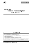
TRANSISTORIZED INVERTER
FR-A500
F 500
E500
FR-A500/F500/E500 series
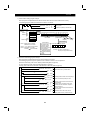
INTRODUCTION
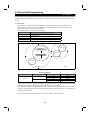
Along with strong wiring-saving needs on the market, there are increasing needs for remote operation and monitoring by
linking a personal computer, PLCs and inverters.
We have been responding to market needs with the MELSECNET/MINI-S3-compatible option units which are the lowerlevel link of our PLCs.
However, various field networks (lower-level link) have been made open mainly in Europe and U.S.A., and recent trends
toward open field networks are rapidly making a deep penetration in the Factory Automation field.
In response to such trends toward open field networks, inverters are also being made open in various ways in the
corresponding areas. To meet such trends, options or special-purpose products developed for compatibility with the
major networks in the world are available for our inverters.
This manual explains the settings, programming methods and other general information of these network-compatible
inverters and options.
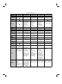
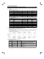
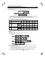
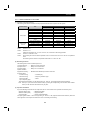
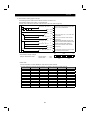
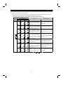
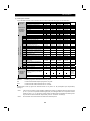
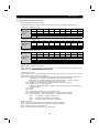
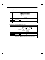
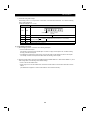
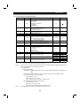
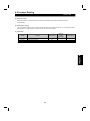
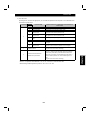
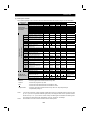
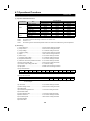
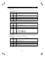
Network Comparison Table
Item
Developed by
Released
RS-485
EIA Standard
April, 1983
CC-Link
Mitsubishi Electric
October, 1996
User group
None
Number of
partners
122
General
SMC, CKD, Idec Izumi,
Sunx, Rika Kogyo,
Yamatake-Honeywell,
Sumitomo Heavy
Industries,
M System Giken,
NEC, Yokogawa
Electric
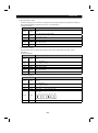
Device bus
General
Main
supporters
Position
Industry
application
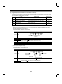
Major area
Communication
speed
Overall distance
Communication
system
Maximum
message size
Connection
cable
Max. number of
nodes
Max. number of
link points
Real scan time
Remarks
Applicable
inverters
DeviceNetTM
Allen Bradley
March, 1994
ODVA
(Open DeviceNet
Vendor Association)
Profibus DP
Siemens, etc.
1994
PNO
(Profibus Netzer
Organization)
250
575
ABB, Omron, Hitachi,
AEG Modicon,
Cutler Hammer,
Square D,
SST, NAMCO
Rockwell, ABB,
Omron, Fesco,
GE Fanuc,
Allen Bradley,
Fuji, AEG Modicon,
Klockner Mueller
Modbus Plus
Modicon
None
Groupe Schneider
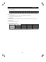
Device bus
Device bus
Device bus
General
Automobile
Automobile
General
General
Asia
North America
Europe
North America, Europe
19.2Kbps maximum
156K to 10Mbps
125K to 500Kbps
9.6K to 12Mbps
38.4Kbps maximum
1200m (156Kbps)
600m (625Kbps)
200m (2.5Mbps)
100m (10Mbps)
500m (125Kbps)
250m (250Kbps)
100m (500Kbps)
1200m (9.6Kbps)
200m (1.5Mbps)
100m (12Mbps)
450m (1Mbps)
450m extendible per
installation of one
repeater, max. 1800m
Master/slave
Master/slave
No limit
500m
Master/slave
Master/slave
Master/slave,
N: N
14 bytes
M D: 150 bytes
D M: 34 bytes
8 bytes
32 bytes
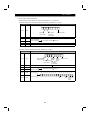
4-wire
(single pair
+ power pair)
64
(including master)
Twisted pair,
fiber-optic
(option)
32
(126 using repeaters)
512 I/O
(I/O 256 each)
Twisted pair
Twisted pair
32
64
2048 I/O
512 words
4ms
(2048 I/O 10Mbps)
7ms (2048 I/O + 512
registers 10Mbps)
Global communication Setting of the standby
standard widely used
master station enables
throughout the world.
data link to be
The values given in the continued if a fault
table are for inverters. occurs in the master
station.
The temporary error
disable station function
allows the unit to be
changed with the data
retained online.
Response time
approximately 25ms
(9600bps)
2048 I/O
7ms (63 devices)
Omron and Hitachi are
actively publicizing in
Japan.
Unsuitable for
communication of large
volumes of
transmission data
because the data that
may be transmitted in
one package is a
maximum 8 bytes.
Twisted pair
61
No limit
(master memory range)
2ms
(512 I/O 12Mbps)
As of April, 1997, about
80% of Profibus nodes
shipped are DP.
The maximum
communication speed
of original 1.5Mbps
was increased to
12Mbps in 1995.
PNO has set up offices
in 15 countries, and
Profibus International
was established in
1995 to integrate
global management.
(PU connector used for (Plug-in option used for (Plug-in option used for (Plug-in option used for
compatibility)
compatibility)
compatibility)
compatibility)
FR-A500 + FR-A5ND
FR-A500 + FR-A5NP
FR-A500
FR-A500 + FR-A5NC
FR-F500 + FR-A5ND
FR-F500 + FR-A5NP
FR-F500
FR-F500 + FR-A5NC
FR-E500
FR-E540 + FR-E5NC
(Plug-in option used for (Dedicated inverter
compatibility)
used for compatibility)
KN
FR-A500 + FR-A5NR
FR-E520FR-F500 + FR-A5NR
Modicon's private
network
(Plug-in option used for
compatibility)
FR-A500 + FR-A5NM
FR-F500 + FR-A5NM
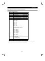
CONTENTS
1 COMPUTER LINK (RS-485)
1
1.1 Overview .................................................................................................................................................................. 1
1.2 Specifications ........................................................................................................................................................... 2
1.3 Structure................................................................................................................................................................... 4
1.3.1 Connection with PU connector (FR-A500, F500) ............................................................................................... 4
1.3.2 Connection with PU connector (FR-E500).......................................................................................................... 5
1.3.3 Connection of FR-A5NR..................................................................................................................................... 6
1.4 Configuration and Wiring Method ............................................................................................................................. 7
1.4.1 Connection with PU connector ........................................................................................................................... 7
1.4.2 Connection of FR-A5NR..................................................................................................................................... 9
1.5 Inverter Setting ....................................................................................................................................................... 11
1.6 Operation Modes .................................................................................................................................................... 13
1.6.1 Connection with PU connector ......................................................................................................................... 13
1.6.2 Connection of FR-A5NR................................................................................................................................... 13
1.7 Operational Functions ............................................................................................................................................ 16
1.8 Computer Programming ......................................................................................................................................... 18
1.9 Troubleshooting...................................................................................................................................................... 22
1.10Setting Items and Set Data..................................................................................................................................... 23
1.11Error Code List ....................................................................................................................................................... 25
2 CC-Link
26
2.1 Overview ................................................................................................................................................................ 26
2.2 Specifications ......................................................................................................................................................... 28
2.3 Structure................................................................................................................................................................. 32
2.3.1 When FR-A5NC is connected .......................................................................................................................... 32
2.3.2 FR-E520-
KN ............................................................................................................................................. 34
2.3.3 When FR-E5NC is connected .......................................................................................................................... 35
2.3.4 Master and local modules................................................................................................................................. 37
2.4 Configuration and Wiring Method ........................................................................................................................... 39
2.5 Inverter Setting ....................................................................................................................................................... 41
2.6 Operation Modes .................................................................................................................................................... 42
2.6.1 When FR-A5NC is connected .......................................................................................................................... 42
2.6.2 FR-E520-
KN ............................................................................................................................................. 45
2.6.3 When FR-E5NC is connected .......................................................................................................................... 46
2.7 Operational Functions ............................................................................................................................................ 48
2.7.1 When FR-A5NC is connected .......................................................................................................................... 48
2.7.2 FR-E520-
KN ............................................................................................................................................. 51
2.7.3 When FR-E5NC is connected .......................................................................................................................... 53
2.8 PLC Programming .................................................................................................................................................. 55
2.9 How to Check for Error with the LED Lamps .......................................................................................................... 69
2.10Troubleshooting...................................................................................................................................................... 72
3 Device NetTM
73
3.1 Overview ................................................................................................................................................................ 73
3.2 Specifications ......................................................................................................................................................... 74
3.3 Structure................................................................................................................................................................. 75
3.4 Configuration and Wiring Procedure....................................................................................................................... 77
3.5 Inverter Setting ....................................................................................................................................................... 80
3.6 Operation Modes .................................................................................................................................................... 84
3.7 Operational Functions ............................................................................................................................................ 87
3.8 DeviceNet Programming ........................................................................................................................................ 89
3.9 Object Map ............................................................................................................................................................. 97
3.9.1 Class 0x01 Identity object................................................................................................................................. 97
3.9.2 Class 0x03 DeviceNet object............................................................................................................................ 98
3.9.3 Class 0x04 Assembly object............................................................................................................................. 98
3.9.4 Class 0x05 DeviceNet connection object ....................................................................................................... 100
3.9.5 Class 0x28 Motor data object ......................................................................................................................... 103
3.9.6 Class 0x29 Control management object......................................................................................................... 103
3.9.7 Class 0x2A AC drive object ............................................................................................................................ 104
3.9.8 Class 0x66 A500 expansion object I............................................................................................................... 106
3.9.9 Class 0x67 A500 expansion object II.............................................................................................................. 110
3.10EDS File ............................................................................................................................................................... 113
4 Profibus-DP
114
4.1 Overview .............................................................................................................................................................. 114
4.2 Specifications ....................................................................................................................................................... 115
4.3 Structure............................................................................................................................................................... 116
4.4 Configuration and Wiring Procedure..................................................................................................................... 118
4.5 Inverter Setting ..................................................................................................................................................... 121
4.6 Operation Modes .................................................................................................................................................. 122
4.7 Operational Functions .......................................................................................................................................... 125
4.8 Profibus Programming.......................................................................................................................................... 127
4.9 Parameter Definitions ........................................................................................................................................... 136
4.9.1 IND=0000H Real-time monitor area ............................................................................................................... 136
4.9.2 IND=01PPH System environment variable area............................................................................................. 137
4.9.3 IND=0200H Standard parameter area............................................................................................................ 138
4.9.4 IND=0300H, Pr. 900 frequency calibration area ............................................................................................. 142
4.9.5 IND=0400H, Pr. 900 % calibration area ......................................................................................................... 143
4.9.6 IND=0800H Programmed operation time setting area.................................................................................... 143
4.9.7 IND=0700H Programmed operation rotation direction setting area ................................................................ 144
4.9.8 IND=0600H Programmed operation frequency setting area........................................................................... 145
4.10Profibus Device Data (GSD File).......................................................................................................................... 146
5 APPENDICES
147
5.1 Data code List ...................................................................................................................................................... 147
5.1.1 FR-A500 series............................................................................................................................................... 147
5.1.2 FR-F500 series............................................................................................................................................... 153
5.1.3 FR-E500 series............................................................................................................................................... 157
chapter 1
1
COMPUTER LINK (RS-485)
1.1 Overview ................................................................................................................ 1
1.2 Specifications ......................................................................................................... 2
1.3 Structure................................................................................................................. 4
1.4 Configuration and Wiring Method ........................................................................... 7
1.5 Inverter Setting ....................................................................................................... 11
1.6 Operation Modes .................................................................................................... 13
1.7 Operational Functions ............................................................................................ 16
1.8 Computer Programming ......................................................................................... 18
1.9 Troubleshooting...................................................................................................... 22
1.10 Setting Items and Set Data................................................................................... 23
1.11 Error Code List ..................................................................................................... 25
1.1 Overview
COMPUTER LINK (RS-485)
1
1.1 COMPUTER
Overview LINK (RS-485)
Computer link allows inverters connected with a computer, such as a personal computer, by communication cables to be
operated and monitored and their parameters to be changed, saved etc. by user programs.
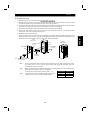
(1) Features of computer link-compatible inverters
1) Communication function is standard.
You can remove the operation panel (or cover etc.) and use RS-485 to perform communication operation via the
PU connector.
Note: A commercially available converter is required when using a computer (personal computer) which only has
RS-232C communication.
2) Plug-in option is also available.
The computer link plug-in option available for the FR-A500 and FR-F500 series inverters and enables RS-485
communication operation to be performed with the Parameter unit (operation panel) connected.
3) Setup Software
The Setup Software which offers an easy-to-use inverter environment is available to support you from inverter
startup to maintenance.
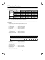
(2) Types of computer link-compatible inverters
Inverter Series
Method for Compatibility with Computer Link
PU connector
Plug-in option
FR-A500
Connected to PU connector
Connect FR-A5NR plug-in option.
FR-F500
Connected to PU connector
Connect FR-A5NR plug-in option.
FR-E500
Connected to PU connector
Incompatible
1
1.2 Specifications
COMPUTER LINK (RS-485)
1.2 Specifications
! Control power: Supplied by the inverter
! Communication power: 5VDC, maximum 60mA
Conforming standard
! [EIA Standard] Shared between RS-422 and RS-485
Transmission form
! Multidrop link system
Communication cable ! Twisted pair cable
Transmission distance ! Maximum 500m overall
Number of inverters
! Up to 10 inverters for RS-422 computer interface
connected
! Up to 32 inverters for RS-485 computer interface
Applicable computer
! Computer with RS-422 or RS-485 interface function
By using a converter, a computer with RS-232C interface function is also
applicable.
(2)
(3)
(4)
(5)
(6)
(7)
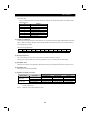
(8) Communication specifications
Connection with PU Connector
Conforming standard
RS-485 Standard
Number of inverters connected
1: N (maximum 32 inverters)
Selectable between 19200, 9600 and
4800bps
Communication speed
Control procedure
Asynchronous system
Communication method
Half duplex system
Communication specifications
Station number setting
Selectable between 19200, 9600, 4800,
2400, 1200, 600 and 300bps
0 to 31
Character system
ASCII (7 bits/8 bits) selectable
Stop bit length
1 bit/2 bits selectable
Terminator
Check system
Connection of FR-A5NR
CR/LF (yes/no selectable)
Parity check
Yes (even/odd)/no selectable
Sum check
Yes
Waiting time setting
Yes/no selectable
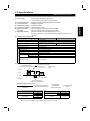
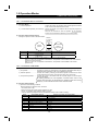
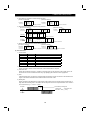
(9) Response time
Inverter data processing time
Data transmission time
= waiting time
(Refer to the following formula)
+
(setting × 10ms)
data check time
(12ms)
Computer
Inverter
Inverter
10ms or longer required
Computer
Data transmission time
(Refer to the following formula)
[Data transmission time formula]
1
Communication speed
(Baudrate)
× Number of data characters ×
(Refer to inverter manual)
Communication
specifications*
(Total number of bits)
= data transmission
time (s)
*Communication specifications (Refer to the following table)
Name
Stop bit length
Data length
Number of Bits
1 bit
2 bits
7 bits
8 bits
Name
Parity check
Start bit
Note: 1 bit is always required for the start bit.
Minimum total number of bits: 9 bits, maximum total number of bits: 12 bits
2
Yes
No
Number of Bits
1 bit
0
1 bit
chapter 1
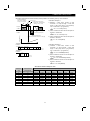
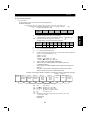
(1) Power supply
COMPUTER LINK (RS-485)
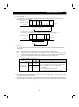
! Example: Response time when forward (reverse) rotation command is given by communication
Data transmission time
(Refer to the calculation
example 1 on the right)
<Calculation example 1>
20ms or more
Inverter data processing time
= waiting time + data check time
(setting × 10ms) + (12ms)
1) Baudrate = 9600 baud, number of data
characters = 12, stop bit length = 2 bits, data
length = 8 bits, parity check = yes (presence),
Computer
CR, LF instructions = yes (presence)
1
9600 × 12 × 12 = 0.015s(15.0ms)
Inverter
Inverter
2) Same conditions as above with the exception of
10ms or longer required
Computer
Output frequency
Data transmission time
(Refer to the calculation example 2 on the right)
baudrate = 300 baud
1 × 12 × 12 = 0.48s(480ms)
300
0
Time
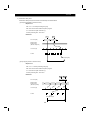
<Example 1>
Format A'
1
<Calculation example 2>
1) Baudrate = 9600 baud, number of data
Inverter
station
number
2
Instruction
code
3
4
5
Waiting
time
ENQ
6
Data
7
Sum check
8
9
10
CR
LF
11
12
characters = 5, stop bit length = 2 bits, data
length = 8 bits, parity check = yes (presence),
Number of
characters
CR, LF instructions = yes (presence)
1
9600 × 5 × 12 = 0.00625s(6.25ms)
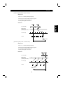
2) Same conditions as above with the exception of
<Example 2>
Format G
ACK
1
baudrate = 19200 baud
1
19200× 12 × 12 = 0.0075s(7.5ms)
3) Same conditions as above with the exception of
Inverter
station
number
2
3
CR
LF
4
5
Number of
characters
baudrate = 19200 baud
1
19200× 5 × 12 = 0.003125s(3.125ms)
3) Same conditions as above with the exception of
baudrate = 300 baud
1 × 5 × 12 = 0.2s(200ms)
300
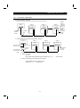
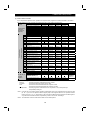
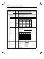
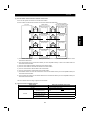
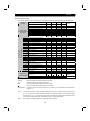
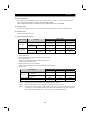
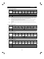
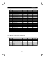
"At-A-Glance" Guide to Response Time
Number of
Data
Characters
Communication
Specifications
(Total number of bits)
Communication Speed (bps)
5
10
166.7ms
83.3ms
41.7ms
20.8ms
10.4ms
5.2ms
2.6ms
5
12
200.0ms
100.0ms
50.0ms
25.0ms
12.5ms
6.3ms
3.1ms
10
10
333.3ms
166.7ms
83.3ms
41.7ms
20.8ms
10.4ms
5.2ms
10
12
400.0ms
200.0ms
100.0ms
50.0ms
25.0ms
12.5ms
6.3ms
12
10
400.0ms
200.0ms
100.0ms
50.0ms
25.0ms
12.5ms
6.3ms
12
12
480.0ms
240.0ms
120.0ms
60.0ms
30.0ms
15.0ms
7.5ms
14
10
466.7ms
233.3ms
116.7ms
58.3ms
29.2ms
14.6ms
7.3ms
14
12
560.0ms
280.0ms
140.0ms
70.0ms
35.0ms
17.5ms
8.8ms
300
600
1200
3
2400
4800
9600
19200
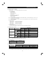
1.3 Structure
COMPUTER LINK (RS-485)
1.3 Structure
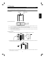
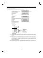
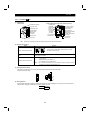
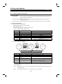
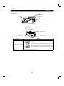
1.3.1 Connection with PU connector (FR-A500, F500)
PU connector
(RS-485)
Modular jack type
junction connector
holder
(2) PU connector pin-outs
1) SG
2) P5S
3) RDA
4) SDB
1)
to
8)
5) SDA
6) RDB
7) SG
8) P5S
Note 1. Do not make connection to the computer LAN board, FAX modem socket or telephone modular connector.
Doing so may damage the product due to differences in electrical specifications.
Note 2. Pins 2 and 8 (P5S) are power supplies for the operation panel or parameter unit. Do not use them when
performing RS-485 communication.
Note 3. Use a commercially available RS-485/RS-232C converter when the personal computer's communication
board has the RS-232C specifications.
(3) Mounting method
1) Hold down the top button of the operation panel and pull the operation panel toward you to remove.
·Removal
2) Unplug the modular jack type junction connector. (Place the removed modular jack type junction connector into
the modular jack type junction connector holder.)
3) Securely plug one end of the connection cable into the PU connector of the inverter and the other end into the
personal computer (or converter etc.).
4
chapter 1
(1) Appearance
COMPUTER LINK (RS-485)
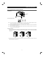
1.3.2 Connection with PU connector (FR-E500)
(1) Appearance
PU connector
(RS-485)
(2) PU connector pin-outs
1) SG
2) P5S
3) RDA
4) SDB
5) SDA
6) RDB
7) SG
8) P5S
8) to 1)
Note 1. Do not make connection to the computer LAN board, FAX modem socket or telephone modular connector.
Doing so may damage the product due to differences in electrical specifications.
Note 2. Pins 2 and 8 (P5S) are power supplies for the operation panel or parameter unit. Do not use them when
performing RS-485 communication.
Note 3. Use a commercially available RS-485/RS-232C converter when the personal computer's communication
board has the RS-232C specifications.
(3) Mounting method
1) Remove the operation panel. Hold down the portion indicated by arrow A in Fig. A and remove the operation
panel as shown in Fig. B. (If you remove it in any other way, force applied to the internal connector may damage
the product.)
A
Fig. A
Fig. B
Fig. C
2) Securely plug one end of the connection cable into the PU connector of the inverter and the other end into the
personal computer (or converter etc.).
5
COMPUTER LINK (RS-485)
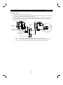
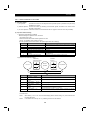
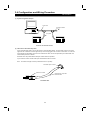
1.3.3 Connection of FR-A5NR
Appearance
Front view
Rear view
Mounting
holes
Mounting
hole
Terminal
block (screw
size M3)
SDA SDB RDA RDB RDR SG
Terminal
symbol
FR-A5NR
A
B
chapter 1
(1)
C
Connector
Option fixing holes
Note: Never use the unused terminals as junction terminals since they are used in the option. Doing so may
damage the option unit.
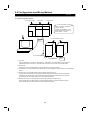
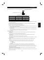
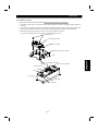
(2) Installation procedure
1) Securely insert the connector of the option unit far into the connector of the inverter. At this time, also fit the
option fixing holes correctly. For the slot positions, refer to the figure below.
2) Securely fix the option unit to the inverter on both sides with the accessory mounting screws. If the screw holes
do not match, the connector may not have been plugged correctly. Check for loose connection.
3) Route the cables so that they do not take up a large space in the control circuit terminal block wiring area of the
option unit.
During wiring, do not leave wire off-cuts in the inverter. They can cause a fault, failure or malfunction.
Use the left-hand side space for routing the cables.
Inverter
(Without cover)
Cable routing
Option unit
Accessory screw
(2 pcs.)
Slot 1
Inverter side connector
Slot 2
Option side
connector
Note 1.
Slot 3
Only one option of the same model may be used. When two or more options are mounted, priority
is in order of slots 1, 2 and 3, and the options having lower priority are inoperative. (Only one
communication option may be used.)
Note 2.
When the inverter cannot recognize that the option is
mounted, it displays "E.OPT".
Note 3.
When one FR-A5NR is used with the other communication
option than the FR-A5NR, no error is displayed and the
relay output of the FR-A5NR and the communication
function of the other communication option are made valid.
Note 4.
Mounting
Position
Error Display
Slot 1
E.OP1
Slot 2
E.OP2
Slot 3
E.OP3
When installing the inverter front cover, the cables to the inverter's control circuit terminals and
option terminals should be routed properly in the wiring space to prevent them from being caught
between the inverter and its cover.
6
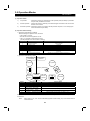
1.4 Configuration and Wiring Method
COMPUTER LINK (RS-485)
1.4 Configuration and Wiring Method
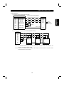
1.4.1 Connection with PU connector
(1) System configuration examples
1) Inverters used with a computer having RS-485 or RS-422 interface
Computer
RS-485/RS-422
interface
terminal
Station 1
Station 2
Station n
Inverter
Inverter
Inverter
PU connector
(Note 1)
PU connector
(Note 1)
PU connector
(Note 1)
Maximum
number
of inverters
connected
RS-422: 10
inverters
RS-485: 32
inverters
Splitter (Note 3)
Termination
resistor
10BASE-T cable (Note 2)
Use the connectors and cables available on the market.
Note 1. Connector: RJ45 connector
Example: 5-554720-3, Japan AMP Co., Ltd.
Note 2. Cable: Cable conforming to EIA568 (e.g. 10BASE-T cable)
Example: SGLPEV 0.5mm × 4P, Mitsubishi Cable Industries, Ltd.
Note 3. Splitter
Example: BMJ-8 modular rosette, Hakko Electrical Mfg. Co., Ltd..........03-3806-9171
2) Inverters used with a computer having RS-232C interface
Computer
RS-232C
connector
RS-232C
cable
Maximum 15m
Station 1
Station 2
Station n
Inverter
Inverter
Inverter
PU connector
(Note 1)
PU connector
(Note 1)
PU connector
(Note 1)
Converter
(Note 3)
Splitter (Note 4)
RS-485 terminal
Termination
resistor
10BASE-T cable (Note 2)
Use the connectors and cables available on the market.
Note 1. Connector: RJ45 connector
Example: 5-554720-3, Japan AMP Co., Ltd.
Note 2. Cable: Cable conforming to EIA568 (e.g. 10BASE-T cable)
Example: SGLPEV 0.5mm × 4P, Mitsubishi Cable Industries, Ltd.
Note 3. Commercially available converter examples:
1) Model: FA-T-RS40
Converter
Nagoya Sales Office, Mitsubishi Electric Engineering Co., Ltd...........052-565-3435
2) Model: DAFXI-CABL series cable with built-in interface
+
DINV-485CAB connector conversion cable
Diatrend Co., Ltd ............06-6460-2100
Note 4. Splitter
Example: BMJ-8 modular rosette, Hakko Electrical Mfg. Co., Ltd. ........03-3806-9171
7
COMPUTER LINK (RS-485)
(2) Wiring method
1) Connection of one RS-485 computer and one inverter
Cable connection and signal direction
Computer Terminals
Inverter
Signal Name
Description
RDA
Receive data
RDB
Receive data
SDB
SDA
RDA
PU connector
10BASE-T cable
SDB
Send data
Send data
RSA
Request to send
RSB
Request to send
CSA
Clear to send
chapter 1
SDA
RDB
CSB
Clear to send
SG
Signal ground
FG
Frame ground
(Note 2)
0.3mm2 or more
SG
2) Connection of one RS-485 computer and n inverters (multiple inverters)
Computer
RDA
RDB
SDA
Termination
resistor
(Note 1)
SDB
SDA
SDB
RDA
RDB
SDA
SDB
RDA
RDB
SDA
SDB
(Note2)
RDA
RSB
CSA
RDB
RSA
CSB
SG
FG
Note 1.
SG
Station 1
SG
Station 2
SG
Station 3
Inverter
Inverter
Inverter
Depending on the transmission speed and/or transmission distance, the inverters may be affected
by reflection. If so, provide a termination resistor. For connection using the PU connector, use a
splitter because a termination connector cannot be fitted. The termination resistor should be
connected to only the remotest inverter from the computer. (Termination resistor: 100 )
Note 2.
Connect in accordance with the manual of the computer used. Note that the computer terminal
numbers depend on the model used.
8
COMPUTER LINK (RS-485)
1.4.2 Connection of FR-A5NR
(1) System configuration examples
1) Inverters used with a computer having RS-485 or RS-422 interface
Computer
RS-485/RS-422
interface
terminal
Station 1
Station 2
Station n
Inverter
Inverter
Inverter
FR-A5NR
FR-A5NR
FR-A5NR
Twisted pair
cable
Maximum
number
of inverters
connected
RS-422: 10
inverters
RS-485: 32
inverters
Termination
resistor
jumper
2) Inverters used with a computer having RS-232C interface
Computer
RS-232C connector
RS-232C cable
Maximum 15m
Station 1
Station 2
Station n
Inverter
Inverter
Inverter
FR-A5NR
FR-A5NR
FR-A5NR
Converter
(Note 1)
Termination
resistor
jumper
RS-422 terminal
RS-485 terminal
Note 1.
Commercially available converter examples:
1)
Model: FA-T-RS40
Converter
Nagoya Sales Office, Mitsubishi Electric Engineering Co., Ltd. ............ 052-565-3435
2)
Model: DAFXI-CABL series cable with built-in interface
+
DINV-485CAB connector conversion cable
Diatrend Co., Ltd. .........06-6460-2100
9
COMPUTER LINK (RS-485)
(2) Wiring method
1) Connection of one computer and one inverter
Cable connection and signal direction
Twisted pair cable (0.3mm2 or more)
Signal name
Description
RDA
Receive data
SDA
RDB
Receive data
SDB
SDA
Send data
RDA
SDB
Send data
RDB
RSA
Request to send
RDR
RSB
Request to send
CSA
Clear to send
CSB
Clear to send
SG
Signal ground
FG
Frame ground
FR-A5NR
(Note 1)
Termination
resistor jumper
(Note 2)
0.3mm2 or more
SG
2) Connection of one computer and n inverters (multiple inverters)
Computer
RDA
RDB
SDA
SDB
SDA
RDA
RDR
SDA
SDB
RDA
RDB
SDA
SDB
RDA
(Note 2)
RDB
RSB
CSA
Termination
resistor
jumper
(Note 1)
RDB
SDB
RSA
CSB
SG
FG
SG
SG
SG
Station 1
Station 2
Station 3
FR-A5NR
FR-A5NR
FR-A5NR
Note 1. The termination resistor jumper should be connected to only the remotest FR-A5NR from the
computer. (Termination resistor: 100 )
Note 2. Connect in accordance with the manual of the computer used. Note that the computer terminal
numbers depend on the model used.
10
chapter 1
Computer Terminals
1.5 Inverter Setting
COMPUTER LINK (RS-485)
1.5 Inverter Setting
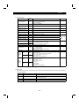
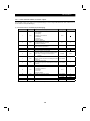
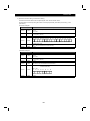
(1) Parameters
<Connection with PU connector>
Parameter Number
117
118
Name
Station number
Communication speed
119
Stop bit length/data length
120
121
122
123
124
Parity check presence/absence
Number of communication retries
Communication check time interval
Waiting time setting
CR, LF presence/absence selection
Setting Range
Setting Increments
0 to 31
1
48, 96, 192
1
0, 1 (data length 8)
1
10, 11 (data length 7)
0, 1, 2
1
0 to 10, 9999
1
0 to 999.8 sec., 9999
0.1
0 to 150ms, 9999
1ms
0, 1, 2
1
Factory Setting
0
192
1
2
1
0 (Note)
9999
1
Note: The factory setting of Pr. 122 for the NA, EC and CH version inverters is "9999".
<Connection of FR-A5NR>
Parameter Number
331
Name
Inverter station number
332
Communication speed
333
Stop bit length/data length
334
335
336
337
338
339
340
341
342
Parity check presence/absence
Number of communication retries
Communication check time interval
Waiting time setting
Operation command write
Speed command write
Link start mode selection
CR, LF presence/absence selection
E2ROM write yes/no
Setting Range
Setting Increments
0 to 31
1
3, 6, 12, 24, 48, 96,
1
192
0, 1 (data length 8)
1
10, 11 (data length 7)
0, 1, 2
1
0 to 10, 9999
1
0 to 999.8 sec., 9999
0.1
0 to 150ms, 9999
1ms
0, 1
1
0, 1
1
0, 1, 2
1
0, 1, 2
1
0, 1
1
Factory Setting
0
96
1
2
1
0
9999
0
0
0
1
0
(2) Station number setting (Pr. 117, Pr. 331 "inverter station number")
1) The station number may be set between 0 and 31.
When the RS-422 interface is used, the station number may be set between 0 and 31 but the number of inverters
connected must be within 10.
2) Note that the same station number cannot be set for different inverters. (If such setting has been made, proper
communication cannot be performed.)
3) Station numbers do not have to be sequential and may be skipped, e.g. as shown below:
Station 3
Station 0
Station 1
Station 21
Station 6
Computer
Station number setting example
(3) Communication specifications
Refer to the following table and set the parameters:
Parameter
Number
Description
118, 332
Communication speed
119, 333
Stop bit length/data
length
120, 334
Parity check
presence/absence
124, 341
CR, LF instruction
presence/absence
Data Setting
Data Definition
3, 6, 12, 24, 48, 3: 300 baud. 6: 600 baud. 12: 1200 baud. 24: 2400 baud.
96, 192 (Note 1) 48: 4800 baud. 96: 9600 baud. 192: 19200 baud (Note 1)
0, 10: Stop bit length = 1 bit 1. 11: Stop bit length = 2 bits.
0, 1, 10, 11
0, 1: Data length = 8 bits. 10, 11: Data length = 7 bits
0: No parity check
0, 1, 2
1: Odd parity
2: Even parity
0: Without CR and LF
0, 1, 2
1: With CR only
2: With CR and LF
Note 1.
The setting range of Pr. 118 is 48, 96 and 192.
Note 2.
The inverter will not be faulty if the Pr. 333 "stop bit length/data length" setting differs from the actual data
value.
11
COMPUTER LINK (RS-485)
(4) Number of data communication error retries
Set the permissible number of retries at occurrence of data receive error. If the number of consecutive errors
exceeds the permissible value, the inverter will come to an alarm stop.
Parameter
Number
Name
Data Setting
0 to 10
121, 335
Number of
communication
retries
9999
(65535) (Note 1)
Data Definition
Permissible number of retries at error occurrence
If the number of retries exceeds the preset value, the inverter will
come to an alarm stop. (Factory-set to one)
If a communication error occurs, the inverter will not come to an alarm
stop. At this time, the inverter can be coasted to a stop by MRS or
RESET input.
During an error, the minor fault signal (LF) is given to the open
collector output. Allocate the used terminal with any of Pr. 190 to
Pr. 195 (output terminal function selection) for A500 series inverters.
Allocate the used terminal with any of Pr. 190 to Pr. 192 for E500
series inverters.
Note: The data to be entered from the parameter unit is 9999 and that from the computer is 65535 (FFFFH).
(5) Permissible communication time interval
Set the permissible communication time interval between the computer and inverter.
(If no-communication with the computer persists for more than the permissible time, the inverter will come to an alarm
stop due to time-out error.)
Parameter
Number
Name
122, 336
Communication
check time
interval
Note 1.
Note 2.
Data Setting
0
Data Definition
Computer link operation disallowed
0.1 to 999.8
Permissible communication time interval (0.1 second increments)
9999(65535)
(Note 1)
Communication check stop
The data to be entered from the parameter unit is 9999 and that from the computer is 65535 (FFFFH).
At power-on (or reset), communication time interval check begins when the first communication is
started.
Note 3.
If the parameter setting is changed, check begins when the change is made.
Note 4.
If communication is broken due to signal cable breakage, computer fault etc., the inverter does not detect
such a fault. This should be fully noted.
2
(6) E ROM write yes/no (connection of FR-A5NR)
2
When the FR-A5NR is connected, choose whether the parameters will be written to E ROM or not.
Parameter
Number
Name
Data Setting
342
E ROM write
yes/no
0
Written to both E ROM and RAM.
1
Written to RAM only.
2
Data Definition
2
12
1.6 Operation Modes
COMPUTER LINK (RS-485)
1.6 Operation Modes
1.6.1 Connection with PU connector
(1) Operation Modes
1) External operation ....................................... Controls the inverter by switching on/off external signals connected
to the control circuit terminals of the inverter.
2) Communication operation (PU connector).... Controls the inverter in accordance with the computer program via
the PU connector.
Since the PU connector is used for operation, the PU operation
mode is the communication operation (PU connector) mode.
(2) Operation mode switching method
Change the operation mode as described below:
Switched
by computer
program
A
Communication
External
operation
operation
(PU connector)
B
Symbol
A
B
Note 1.
Switching Type
Communication operation (PU connector)
external operation
communication operation
External operation
(PU connector)
Switching Method
By the user program of the computer (Note 1)
By the user program of the computer (Note 1)
Set "0" in Pr. 79 "operation mode selection" to carry out the above switching.
When "1" is set in Pr. 79 "operation mode selection", the operation mode available is the communication
operation (PU connector) only.
When "2" is set in Pr. 79 "operation mode selection", the operation mode available is the external
operation only.
1.6.2 Connection of FR-A5NR
(1) Operation modes
1) PU operation ......................... Controls the inverter from the keyboard of the operation panel/parameter unit (FRDU04/FR-PU04) (referred to as the "PU") installed to the inverter.
2) External operation ................. Controls the inverter by switching on/off external signals connected to the control
circuit terminals of the inverter. (The inverter is factory-set to this mode.)
3) Computer link operation ........ Controls the inverter in accordance with the computer program via the computer
link unit (FR-A5NR).
By setting parameters Pr. 338 "operation command write" and Pr. 339
"speed command write" as appropriate, the operation signal and running
frequency can be entered from the control circuit terminals.
(2) Operation mode switching
1) Operation mode switching conditions
Before switching the operation mode, check that:
! The inverter is at a stop.
! Both the forward and reverse rotation signals are off; and
! The Pr. 79 "operation mode selection" setting is correct.
(Use the operation panel/parameter unit (FR-DU04/FR-PU04) of the inverter for setting.)
Setting
Operation Mode Selection
0
PU or external operation
1
2
3
4
PU operation only
External operation only
External/PU combined operation
External/PU combined operation
5
Programmed operation
6
Switch-over
7
External operation (PU interlock signal)
8
PU or external (signal switching)
Switching to Computer Link Operation Mode
Disallowed when the PU mode is selected. Allowed when the external
mode is selected.
Disallowed
Allowed
Disallowed
Disallowed
Disallowed (Parameter values write-enabled in the external operation
mode may be changed)
Allowed
Allowed only in the external operation mode when the PU interlock signal
(X12) is on.
Allowed only in the external operation mode (X16 on).
13
COMPUTER LINK (RS-485)
2) Operation mode switching
method
Switched
Switched
by computer
by parameter
program
unit
Change the operation mode as
described below:
A
C
Computer
External
link
PU operation
operation
operation
D
B
E
F
(Switching disallowed)
Symbol
A
B
C
D
E
F
Switching Type
PU operation
external operation
External operation
PU operation
computer link
External operation
operation
external
Computer link operation
operation
computer link
PU operation
operation
PU
Computer link operation
operation
Switching Method
Operate the external operation key sheet on the PU.
Operate the PU operation key sheet on the PU.
By the user program of the computer.
By the user program of the computer.
Switching disallowed/allowed if external operation is selected in A and
computer link operation is then selected in C. (Note 2)
Switching disallowed/allowed if external operation is selected in D and PU
operation is then selected in B. (Note 2)
When "1 or 2" is set in Pr. 340 "link start mode selection", the operation mode is computer link operation at
power on or inverter reset.
Note 1. When setting "1 or 2" in Pr. 340, the initial settings (station number setting, etc.) of the inverter must be
made without fail.
Note 2. In the switch-over mode, switching in E and F is also allowed.
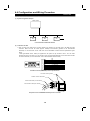
3) Operation mode display
The operation mode is displayed on the PU as indicated below:
! PU operation .................... PU
! External operation ............ EXT
! Computer link operation ... NET
4) Operation mode at power on and instantaneous power failure
By setting the Pr. 340 "link start mode selection" value as appropriate, the operation mode at power on and at
restoration from instantaneous power failure can be selected.
Pr. 340
Setting
Pr.79
0
1
2
3
0
4
5
6
7
8
Operation Mode Name
Mode at Power On or at Restoration from Instantaneous Power Failure
PU or external operation
PU operation only
External operation only
External/PU combined
operation mode
External/PU combined
operation mode
Programmed operation mode
Switch-over mode
External operation mode
External/PU combined
operation mode
Inverter goes into the external operation mode.
Inverter goes into the PU operation mode.
Inverter goes into the external operation mode.
Running frequency is set in the PU operation mode and the start signal is set in
the external operation mode.
Running frequency is set in the external operation mode and the start signal is
set in the PU operation mode.
Inverter is operated by the program.
Operation mode is switched while running.
Shift to the PU operation mode is controlled by ON/OFF of the X12 signal.
1
Computer link operation
2
Computer link operation automatic
restart after instantaneous power
failure
Operation mode is switched by ON/OFF of the X16 signal.
Inverter goes into the computer link operation mode. (Program need not be used for
switching)
When the computer link unit (FR-A5NR) is fitted and Pr. 57 setting is other than
9999 (setting of automatic restart after instantaneous power failure), automatic
restart is made in the status prior to the occurrence of instantaneous power
failure to continue computer link operation, if no communication signal is given
from the computer. (Program need not be used for switching)
Note 1. If an instantaneous power failure occurs during computer link operation, the programming of the
computer stops and remains stopped if power is restored.
If an instantaneous power failure occurs with "2" set in Pr. 340 "link start mode selection", the inverter
9999)
continues operation in the status prior to the instantaneous power failure. (When Pr. 57
! The Pr. 340 value may be changed in any operation mode.
! To start computer link operation at power-on, set "1 or 2" in Pr. 340.
14
COMPUTER LINK (RS-485)
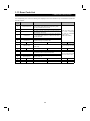
(3) Control location selection
In the computer link operation mode, operation can be performed by signals from external terminals in accordance
with the settings of Pr. 338 "operation command write" and Pr. 339 "speed command write".
Control place
selection
Fixed functions
(Functions
equivalent to
terminals)
0
1
2
3
4
5
Pr. 180 to Pr. 186 settings
Selective functions
6
7
8
9
10
11
12
13
14
15
16
17
18
19
20
22
23
RH, RM, RL, RT
selection
functions
Operation command write (Pr. 338)
0: Computer
Speed command write (Pr. 339)
0: Computer
Forward rotation command (STF)
Computer
Reverse rotation command (STR)
Computer
Start self-holding selection (STOP)
Output halt (MRS)
Both
Reset (RES)
Both
Computer link operation frequency
Computer
2
4
1
Compensation
Low-speed operation command (RL)
Computer
Middle-speed operation command
Computer
(RM)
High-speed operation command
Computer
(RH)
Second function selection (RT)
Computer
Current input selection (AU)
Jog operation selection (JOG)
Automatic restart after
External
instantaneous power failure
selection (CS)
External thermal relay input (OH)
External
15-speed selection (REX)
Computer
Third function (X9)
Computer
FR-HC connection, inverter
External
operation enable (X10)
FR-HC connection, instantaneous
External
power failure detection (X11)
PU external interlock (X12)
External
External DC dynamic braking start
Computer
(X13)
PID control valid terminal (X14)
Computer
Brake opening completion signal
Computer
(BRI)
PU operation-external operation
External
switching (X16)
Load pattern selectionforward/reverse rotation boost
Computer
switching (X17)
Magnetic flux-V/F switching (X18)
Computer
Load torque high-speed frequency
Computer
(X19)
S-pattern acceleration/deceleration
Computer
C switch-over terminal
Orientation command
Computer
Pre-excitation
Computer
Remote setting (RH, RM, RH)
Computer
0: Computer
1: External
Computer
Computer
Both
Both
External
External
External
External
1: External
0: Computer
External
External
External
External
Both
Computer
1: External
1: External
External
External
External
External
Both
Computer
Computer
(Note 1)
Compensation
Computer
External
External
External
External
Pr. 59 = 0
External
Computer
External
Pr. 59 = 0
External
Computer
External
Pr. 59 = 0
Computer
Both
External
External
External
Both
External
External
External
External
External
External
Computer
External
Computer
External
External
External
External
External
External
External
External
External
External
External
External
External
Computer
External
External
External
Computer
External
Computer
External
External
External
External
External
Computer
External
External
Computer
External
External
Computer
External
External
Computer
External
External
Computer
Computer
External
External
External
Computer
External
External
External
External
Computer
Computer
External
External
External
Programmed operation group
selection (RH, RM, RL)
Stop-on-contact selection 0 (RL)
Stop-on-contact selection 1 (RT)
Remarks
Pr. 59 = 0
(Note 2)
Pr. 59 = 1, 2
Pr. 79 = 5
Computer link
operation
disallowed
Pr. 270 = 1, 3
[Explanation of table]
External
: Control by signal from external terminal only is valid.
Computer
: Control from sequence program only is valid.
Both
: Control from both external terminal and computer is valid.
: Control from both external terminal and computer is invalid.
Compensation : Control by signal from external terminal is only valid if Pr. 28 (multi-speed input
compensation) setting is 1.
Note 1. If the FR-HC is connected, inverter operation enable signal (X10) is not assigned when the FR-HC is used
(Pr. 30 = 2) or if the PU operation interlock signal (X12) is not assigned when the PU operation interlock
function is set (Pr. 79 = 7). This function is also used by the MRS signal and therefore the MRS signal is
only valid for the external terminals, independently of the Pr. 338 and Pr. 339 settings.
Note 2. The orientation command needs the FR-A5AP and FR-A5AX options.
15
1.7 Operational Functions
COMPUTER LINK (RS-485)
1.7 Operational Functions
(1) Operation mode-based functions
Operation Mode
Control location
Item
PU operation
External operation
Computer link operation
(when FR-A5NR is used)
Operation command
(start)
Allowed
Disallowed
Disallowed
Running frequency
setting
Allowed
Allowed (combined
mode)
Disallowed
Computer user program
Monitoring
from PU connector
Parameter write
Allowed
Allowed
Allowed
Allowed (Note 4)
Allowed (Note 4)
Allowed (Note 4)
Parameter read
Allowed
Allowed
Allowed
Inverter reset
Allowed
Allowed
Allowed
Stop command (Note 3)
Allowed
Allowed
Allowed
Operation command
Disallowed
Disallowed
Allowed (Note 1)
Running frequency
setting
Disallowed
Disallowed
Allowed (Note 1)
Computer user program Monitoring
Parameter write
from FR-A5NR
Allowed
Allowed
Allowed
Disallowed (Note 4)
Disallowed (Note 4)
Disallowed (Note 4)
Allowed
Allowed
Allowed
Inverter reset
Disallowed
Disallowed
Allowed
Stop command (Note 3)
Disallowed
Disallowed
Allowed
Parameter read
Inverter reset
Control circuit terminal
Allowed
Allowed
Allowed
Operation command
Disallowed
Allowed
Allowed (Note 1)
Frequency setting
Disallowed
Allowed
Allowed (Note 1)
Note 1.
Depends on the Pr. 338 "operation command write" and Pr. 399 "speed command write" settings.
Note 2.
Cannot be reset from the computer when an RS-485 communication error occurs.
Note 3.
Depends on the Pr. 75 "reset selection" setting.
Note 4.
Depends on the Pr. 77 "parameter write inhibit selection" setting.
(2) Input from computer to inverter
1) Operation commands ...... The following command can be given:
<Connection via PU connector>
<Connection via FR-A5NR>
Bit 0:
Bit 0: Current input selection (AU)*
1: Forward rotation (STF)
1: Forward rotation (STF)
2: Reverse rotation (STR)
2: Reverse rotation (STR)
3:
3: Low speed (RL)*
4:
4: Middle speed (RM)*
5:
5: High speed (RH)*
6:
6: Second acceleration/deceleration (RT)*
7:
7: Output halt (MRS)
The input signals marked * can be changed using Pr. 180 to Pr. 186 (input terminal function selection) for A500
and F500 series inverters.
2) Running frequency
The output frequency of the inverter can be set between 0 and 400Hz (16-bit binary in 0.01Hz increments)
3) Inverter reset
The inverter can be reset from the computer.
4) Parameter setting write
For the parameters indicated in Appendix "Data Code List", their settings can be written.
16
COMPUTER LINK (RS-485)
(3) Input from inverter to computer
1) Inverter status .......... The following operating status can be monitored.
Bit 0: Running (RUN)*
1: Forward running
2: Reverse running
3: Up to frequency (SU)*
4: Overload (OL)*
5: Instantaneous power failure (IPF)*
6: Frequency detection (FU)*
7: Alarm occurrence*
Note 1. For the FR-A500 and F500 series, the output signals marked * can be changed using Pr. 190 to Pr. 195
(output terminal function selection).
Note 2. The E500 series uses Pr. 190 to Pr. 192. Also, for the FR-E500 series, bit 5: Instantaneous power failure
(IPF) is not available.
2) Inverter monitoring
! Output frequency ...... Binary in 0.01Hz increments
! Output current........... Binary in 0.01A increments
! Output voltage .......... Binary in 0.1V increments
! Alarm definition ........ Binary (up to eight alarms)
3) Parameter setting read
For the parameters indicated in Appendix "Data Code List", their settings can be read.
(4) Operation at alarm occurrence
Alarm Location
Inverter fault
Description
PU operation
Inverter operation
PU connector
Data
communFR-A5NR
ication
Inverter operation
Communication error
(communication from PU
connector)
Communication error
(plug-in option)
PU connector
Data
communFR-A5NR
ication
Inverter operation
PU connector
Data
communFR-A5NR
ication
Operation Mode
External
Computer link operation
operation
(when FR-A5NR is used)
Stop
Continued
Stop
Continued
Stop
Continued
Continued
Continued
Continued
Stop/continued
(Note 1)
Stop
Continued
Continued
Stop
Stop
Continued
Continued
Continued
Continued
Continued
Continued
Continued
Stop/continued (Note 2)
Continued
Stop
Stop
Stop
Note 1.
Can be selected by parameter setting (factory-set to continued).
Note 2.
Can be selected by parameter setting (factory-set to stop).
(5) Communication error
Error Location
Communication error
(communication from PU connector)
Communication error (FR-A5NR)
Error Code
E.PUE
E.OP1 to E.OP3
(6) Inverter reset
Operation Mode
Resetting Method
Computer user program
Terminals RES-SD ON
Inverter power OFF
PU operation
External operation
Computer link operation
(when FR-A5NR is used)
Disallowed
Allowed
Allowed
Disallowed
Allowed
Allowed
Allowed (Note)
Allowed
Allowed
Note: When the inverter is reset in the computer link operation mode, it is put in the external operation mode.
Accordingly, to resume computer link operation, switch the operation mode to computer link operation again.
17
1.8 Computer Programming
COMPUTER LINK (RS-485)
1.8 Computer Programming
(1) Communication protocol
Data communication between the computer and inverter is performed using the following procedure:
Data read
Computer
(Data flow)
*2
1)
Inverter
4)
Inverter
5)
Time
3)
2)
*1
(Data flow)
Data write
Computer
*1. If a data error is detected and a retry must be made, execute retry operation with the user program. The inverter
comes to an alarm stop if the number of consecutive retries exceeds the parameter setting.
*2. On receipt of a data error occurrence, the inverter returns retry data 3 to the computer again. The inverter comes
to an alarm stop if the number of consecutive data errors reaches or exceeds the parameter setting.
(2) Communication operation presence/absence and data format types
Communication operation presence/absence and data format types are as follows:
No.
1)
2)
3)
4)
5)
Operation Running Parameter
command Frequency
Write
Communication request is sent to the inverter in
A
A
accordance with the user program.
A’
(A”)
(A”)
(Note)
(Note)
Inverter data processing time
Present
Present
Present
No error
C
C
C
Request
Reply data from the inverter
accepted
(Data 1 is checked for error)
With error
Request
D
D
D
rejected
Computer processing delay time
Absent
Absent
Absent
No error
Absent
Absent
Absent
Answer from computer in
No processing
response to reply data 3
With error
(Data 3 is checked for error)
Absent
Absent
Absent
3 is output
Operation
Inverter
Reset
Monitoring
Parameter
Read
A
B
B
Absent
Present
Present
Absent
E,E’
(E”) (Note)
E
Absent
F
F
Absent
Absent
Absent
Absent
G
G
Absent
H
H
Note: For the FR-E500 series, the data format is A" or E" when you set any of "0.01 to 9998" in Pr. 37 "output
frequency setting" and "1" in the data code "HFF".
(3) Data format
Hexadecimal data is used.
Data is automatically transferred in ASCII between the computer and inverter.
! Data format types
1) Communication request data from computer to inverter
Format A'
*3
ENQ
1
Format A"
*3
ENQ
[Data read]
1
Format B
*3
ENQ
1
2
3
Inverter
station
number
2
3
Inverter
station
number
2
3
Inverter
station
number
2
3
Instruction
code
4
5
Instruction
code
4
5
Instruction
code
4
5
Instruction
code
4
5
6
Waiting
time *5
1
Inverter
station
number
6
6
6
Sum
check
Data
7
8
Data
7
8
Waiting
time
*3
ENQ
Waiting
time *5
Format A
Waiting
time *5
[Data write]
9
10
11
Sum
check
*4
9
11
10
*4
12
Number of characters
Sum
check
Data
7
8
9
Sum
check
*4
7
9
8
Number of characters
13
10
11
12
13
14
*4
15
Number of
characters
Number of characters
Note 1. The inverter station numbers may be set between H00 and H1F (stations 0 and 31) in hexadecimal.
Note 2. *3 indicates the control code.
Note 3. *4 indicates the CR or LF code.
When data is transmitted from the computer to the inverter, code CR (carriage return) or LF (line feed) is
automatically set at the end of a data group on some computers. In this case, setting must also be made
from the inverter according to the computer.
Also, the presence and absence of the CR and LF codes can be selected using Pr. 124 (Pr. 341).
Note 4. *5: When Pr. 123 (Pr. 337) "waiting time setting" 9999, create the communication request data with no
"waiting time" in the data format. (The number of characters decreases by 1.)
18
COMPUTER LINK (RS-485)
2) Send data from computer to inverter during data write
[No data error detected]
*3
ACK
Format C
1
[Data error detected]
Inverter
station
number
*4
2
4
3
*3
NAK
Format D
Number of characters
Inverter
station
number
1
2
3
Error
code
*4
4
5
Number of characters
3) Reply data from inverter to computer during data read
[No data error detected]
*3
STX
Format E
1
*3
STX
Format E'
1
*3
STX
Format E"
1
[Data error detected]
Inverter
station
number
2
3
Inverter
station
number
2
3
Inverter
station
number
2
3
Read data
4
5
Read
data
4
6
*3
ETX
5
6
*3
ETX
Sum
check
*4
8
9
11
Sum
check
*4
7
9
7
8
5
6
7
8
9
*3
NAK
1
Inverter
station
number
2
3
Error
code
*4
4
5
Number of characters
*3
ETX
Read data
4
10
Format F
Sum
check
10
11
12
*4
13
Number of characters
4) Replay data from computer to inverter during data read
[No data error detected]
Format G
*3
ACK
[Data error detected]
Inverter
station
number
1
2
Format H
*4
3
4
*3
NAK
Number of characters
1
Inverter
station
number
*4
2
4
3
Number of characters
(4) Data definitions
1) Control codes
Signal Name
ASCII Code
STX
H02
Description
Start Of Text (Start of data)
ETX
H03
End Of Text (End of data)
ENQ
H05
Enquiry (Communication request)
ACK
H06
Acknowledge (No data error detected)
LF
H0A
Line Feed
CR
H0D
Carriage Return
NAK
H15
Negative Acknowledge (Data error detected)
2) Inverter station number
Specify the station number of the inverter which communicates with the computer.
3) Instruction code
Specify the processing request (e.g. operation, monitoring) given by the computer to the inverter. Hence, the
inverter can be run and monitored in various ways by specifying the instruction code as appropriate.
4) Data
Indicates the data such as frequency and parameters transferred to and from the inverter. The definitions and
ranges of set data are determined in accordance with the instruction codes.
5) Waiting time
Specify the waiting time between the receipt of data at the inverter from the computer and the transmission of
reply data. Set the waiting time in accordance with the response time of the computer between 0 and 150ms in
10ms increments (e.g. 1 = 10ms, 2 = 20ms).
Computer
Inverter data processing time
= waiting time
date check time
+
(set value × 10ms) (12ms)
Inverter
Inverter
Computer
19
COMPUTER LINK (RS-485)
6) Sum check code
The sum check code is 2-digit ASCII (hexadecimal) representing the lower 1 byte (8 bits) of the result (sum)
(Example 1)
Computer
inverter
ASCII code
E
N
Q
05H
Station
number
Instruction
code
* Waiting
time
derived from the checked ASCII data.
Sum
check
code
Data
0
1
E
1
1
0
7
A
D
F
4
30H
31H
45H
31H
31H
30H
37H
41H
44H
46H
34H
Binary code
H H H H H H H H H
30+31+45+31+31+30+37+41+44
H
=1F4
Sum
*When Pr. 123 (Pr. 337) "waiting time setting"
9999, create the communication
request data with no "waiting time" in the data format. (The number of characters decreases by 1.)
(Example 2)
Computer
inverter
ASCII code
S
T
X
02H
Station
number
Read data
E
T
X
0
1
1
7
7
0
30H
31H
31H
37H
37H
30H
03H
Sum
check
code
3
0
33H
30H
Binary code
H H H H H H
30+31+31+37+37+30
H
=130
Sum
7) Error code
If any error is found in the data received by the inverter, its definition is sent back to the computer together with
the NAK code.
Note 1.
Note 2.
When the data from the computer has an error, the inverter will not accept that data.
A request of any data communication, e.g. operation command, monitoring, is always given by the
computer and the inverter will not return data to the computer. Hence, the program should be written to
give a data read request as required from the computer at the time of monitoring, etc.
Note 3.
Data for link parameter expansion setting differs as indicated below between access to Pr. 0-Pr. 99
values and access to Pr. 100 and later:
Instruction
Code
Read
7FH
Write
FFH
Link parameter
expansion setting
Data
00H: Pr. 0 to Pr. 99 values are accessible.
01H: Pr. 100 to Pr. 159, Pr. 200 to Pr. 231 and Pr. 900 to Pr. 905
values are accessible.
02H: Pr. 160 to Pr. 199 and Pr. 232 to Pr. 285 values are
accessible.
03H: Pr. 300 to Pr. 399 values are accessible.
09H: Pr. 990 value is accessible (and other 900 parameters).
(5) Programming instructions
1) The inverter does not accept data from the computer if it has an error. For this reason, a retry program for data
error must be included in the user program.
2) A request of any data communication, e.g. operation command, monitoring, is always given by the computer and
the inverter will not return data to the computer. Hence, the program should be written to give a data read request
as required from the computer at the time of monitoring, etc.
20
COMPUTER LINK (RS-485)
(6) Program example (BASIC)
When the operation mode is switched to communication operation
Initial setting of I/O file
10 OPEN “COM1:9600,E,8,2,HD” AS#1
20 COMST1,1,1:COMST1,2,1
30 ON COM(1)GOSUB*REC
40 COM(1)ON
:Communication file opening
:Circuit control signal (RS, ER) ON/OFF setting
:Interrupt definition at data receive
:Interrupt enable
50 D$= “01FB10002”
Transmission data setting
60 S=0
70 FOR I=1 TO LEN(D$)
80 A$=MID$(D$,I,1)
Sum code calculation
90 A=ASC(A$)
100 S=S+A
110 NEXT I
120 D$=CHR$(&H5)+D$+RIGHT$(HEX$(S),2) :Addition of control and sum codes
130 PRINT#1,D$
Data transmission
140 GOTO 50
Interrupt data receive
1000 *REC
1010 IF LOC(1)=0 THEN RETURN
:Interrupt occurrence at data receive
1020 PRINT “RECEIVE DATA”
1030 PRINT INPUT$(LOC(1),#1)
1040 RETURN
General flowchart
Line number
10
Input file
to
initial setting
40
50
to
Transmission
data processing
·Data setting
·Sum code
calculation
·Data transmission
1000
Interrupt to
1040
Receive data
processing
·Data import
·Screen display
140
Note 1. When the inverter's communication check time interval is not set, interlocks are provided to disable
operation to prevent hazards. Always set the communication check time interval before starting
operation.
Note 2. Data communication is not started automatically but is made only once when the computer provides a
communication request. If communication is disabled during operation due to signal cable breakage
etc., the inverter cannot be stopped. When the communication check time interval has elapsed, the
inverter will come to an alarm stop. The inverter can be coasted to a stop by switching on its RES
signal or by switching power off.
Note 3. If communication is broken due to signal cable breakage, computer failure etc., the inverter does not
detect such a fault. This should be fully noted.
21
1.9 Troubleshooting
COMPUTER LINK (RS-485)
1.9 Troubleshooting
(1) Data from computer unread by inverter
1) Computer conforming to RS-422 or RS-485 Standard?
2) Communication cables (and FR-A5NR) fitted properly? (Check for contact fault, open cable, wrong polarity, etc.)
3) Inverter initialization correct?
4) Station number setting (Pr. 117, Pr. 331) proper? (Check that setting and program matches and that the same
station number is not used for different inverters.)
5) Communication check time interval (Pr. 112, Pr. 336) other than 0?
6) Proper communication request program executed in computer?
(2) Operation mode unswitched to computer link operation
1) When inverter is switched from external operation, are the signals to the external terminals STF or STR off?
2) Proper operation mode switching program executed?
(3)
Inverter unstarted in computer link mode
1) Inverter starting program executed properly?
2) Control location select conditions set properly when FR-A5NR is connected?
3) Inverter output provided?
4) Permissible communication time interval set properly?
(4) Inverter brought to alarm stop during operation due to communication error
1) Communication cables (and FR-A5NR) fitted properly? (Check for contact fault, open cable, etc.)
2) Computer operating without fault?
3) Program written to give communication request from computer periodically?
4) Permissible communication time interval set properly?
5) Format of data transferred proper?
6) Termination resistor jumper connected?
22
1.10 Setting Items and Set Data
COMPUTER LINK (RS-485)
1.10 Setting Items and Set Data
After completion of parameter setting, set the instruction codes and data as indicated below and start communication
from the computer to allow various types of operation control and monitoring.
No.
1
Instruction
Code
Item
Read
7BH
Write
FBH
Operation mode
Output frequency
[speed]
6FH
Output current
Output voltage
Special monitor (Note 1)
70H
71H
72H
Number of Data
Digits
Description
0000H: Communication option operation (connection of FR-A5NR)
0001H: External operation
0002H: Communication operation (PU connector), PU operation
0000H: Communication option operation (connection of FR-A5NR)
0001H: External operation
0002H: Communication operation (PU connector)
0000H to FFFFH: Output frequency (hexadecimal) in 0.01Hz
increments
[Speed (hexadecimal) in 1r/min increments if Pr. 37 = 1 to 9998 or
Pr. 144 = 2 to 10, 102 to 110.]
0000H to FFFFH: Output current (hexadecimal) in 0.01A increments
0000H to FFFFH: Output voltage (hexadecimal) in 0.1V increments
0000H to FFFFH: Monitored data selected by instruction code F3H
4 digits
4 digits
4 digits
4 digits
4 digits
01H to 0EH: Monitor selection data
Data
01H
Read
73H
Special monitor
selection No.
(Note 1)
2
Increments Data
0.01Hz
09H
Description
Regenerative
brake
Increments
0.1%
Electronic
overcurrent
protection load
factor
Output current
peak value
Converter
output voltage
peak value
02H
Output current
0.01A
0AH
03H
Output
voltage
0.1V
0BH
05H
Frequency
setting
0.01Hz
0CH
06H
Running
speed
1r/min
0DH
Input power
0.01kW
07H
Motor torque
0.1%
0EH
Output power
0.01kW
F3H
Monitoring
Write
Description
Output
frequency
0.1%
2 digits
0.01A
0.1V
0000H to FFFFH: Two most recent alarm definitions
Alarm definition display example (instruction code 74H)
Read data: [Example] 30A0H
(Previous alarm ........ THT)
(Most recent alarm ..... OPT)
b15
b8b7
b0
0 0 1 1 0 0 0 0 1 0 1 0 0 0 0 0
Previous alarm
(H30)
Most recent alarm
(HA0)
Alarm data
Data
Alarm definition
74H to 77H
Description
Data
Description
Data
Description
No alarm
00H
60H
OLT
C0H(*)
CPU
10H
OC1
70H
BE
C1H(*)
CTE
11H
OC2
80H(*)
GF
C2H(*)
P24
12H
OC3
81H(*)
LF
D5H(*)
MB1
20H
OV1
90H
OHT
D6H(*)
MB2
21H
OV2
A0H(*)
OPT
D7H(*)
MB3
22H
OV3
A1H(*)
OP1
D8H(*)
MB4
30H
THT
A2H(*)
OP2
D9H(*)
MB5
31H
THM
A3H(*)
OP3
DAH(*)
MB6
40H
FIN
BOH
PE
DBH(*)
MB7
50H(*)
IPF
B1H
PUE
F6H(*)
E6
51H(*)
UVT
B2H
RET
F7H(*)
E7
*Alarm
data
unavailable
for
FR-E500
series.
C0H(CPU) is output only when FR-A5NR is used.
4 digits
00H to FFH: Operation command
[Example 1] 02 H ... Forward rotation
[Example 2] 00 H ... Stop
3
Operation command
FAH
b7
b0
0 0 0 0 0 0 1 0
(For Example 1)
<Connection with PU connector> <Connection of FR-A5NR>
b0:
b0: Current input selection (AU)*
b1: Forward rotation (STF)
b1: Forward rotation (STF)
b2: Reverse rotation (STR)
b2: Reverse rotation (STR)
b3:
b3: Low speed (RL)*
b4:
b4: Middle speed (RM)*
b5:
b5: High speed (RH)*
b6:
b6: Second acceleration/deceleration (RT)*
b7:
b7: Output halt (MRS)
The input signals marked * can be changed using input terminal
assignment functions.
Note 1.
Special monitoring is not available for the FR-E500 series.
23
2 digits
COMPUTER LINK (RS-485)
No.
Instruction
Code
Item
4
Inverter status monitor
7AH
5
Running frequency write
E2PROM
EEH
6
Alarm definition batch clear
F4H
7
All parameter clear
FCH
8
User clear
FCH
9
Inverter reset
FDH
10
Parameter write
80H to E3H
11
Parameter read
00H to 63H
12
13
Link
parameter
expansion
setting
Second
parameter
changing
(Instruction
code FFH=1)
Read
7FH
Write
FFH
Read
6CH
Write
ECH
Description
00H to FFH: Inverter status monitor
[Example 1] 02H ... Forward running b7
b0
[Example 2] 80H ... Stop due to
0 0 0 0 0 0 1 0
alarm occurrence
(For Example 1)
b0: Inverter running (RUN)*
b1: Forward running (STF)
b2: Reverse running (STR)
b3: Up to frequency (SU)*
b4: Overload (OL)*
b5: Instantaneous power failure (IPF)*
b6: Frequency detection (FU)*
b7: Alarm occurrence*
* For the FR-A500 and F500 series, outputs change with the
settings of Pr. 190 to Pr. 195.
Instantaneous power failure (IPF) is not available for the FRE500 series.
0000H to 9C40H: 0.01Hz increments (hexadecimal)
0 to 400.00Hz
To change the running frequency consecutively, write data to the
inverter RAM. (Instruction code: EDH)
9696H: Batch-clears the alarm history.
All parameters return to the factory settings.
Any of four different clear operations is performed according to the
data.
ECH
Pr. Communic- Calibration
Other Pr.
F3H
ation
Pr.
Pr.
Data
FFH
9696H
9966H
5A5AH•
55AAH•
When all parameter clear is executed with 9696H or 9966H,
communication-related parameter settings also return to the
factory settings. When resuming operation, therefore, make
parameter setting again.
* 5A5AH and 55AAH are not available when the FR-A5NR is
connected.
9669H User clear is made.
(Unavailable for FR-E500 series)
ECH
Communication Calibration
Other Pr.
F3H
Pr.
Pr.
FFH
9696H: Resets the inverter.
As the inverter is reset at start of communication by the computer,
the inverter cannot send reply data back to the computer.
Refer to Appendices and write and/or read parameter values as
required.
Note that some parameters may be inaccessible.
Parameter values of 00H to 6CH and 80H to ECH are changed.
00H: Pr. 0 to Pr. 99 values are accessible.
01H: Pr. 100 to Pr. 159 , Pr. 200 to Pr. 231 and Pr. 900 to Pr. 905
values are accessible.
02H: Pr. 160 to Pr. 199 and Pr. 232 to Pr. 285 values are
accessible.
03H: Pr. 300 to Pr. 399 values are accessible.
09H: Pr. 992, Pr. 923, Pr. 990 and Pr. 991 values are accessible.
When setting the programmed operation (data codes 3DH to 5AH,
BDH to ADH) parameters (Unavailable for FR-E500 series)
00H: Running frequency
6 3 3 B
01H: Time
02H: Rotation direction
Time (Min.) Min. (Sec.)
When setting the bias/gain (data codes 5EH to 6AH, DEH to EDH)
parameters
00H: Offset/gain
01H: Analog
02H: Analog value of terminal
24
Number of Data
Digits
2 digits
4 digits
4 digits
4 digits
4 digits
4 digits
4 digits
2 digits
2 digits
1.11 Error Code List
COMPUTER LINK (RS-485)
1.11 Error Code List
The corresponding error code in the following list is displayed if an error is detected in any communication request data
from the computer:
Error
Code
Item
0H
Computer NAK error
1H
Parity error
The parity check result does not match the specified parity.
2H
Sum check error
Sum check code in the computer does not match that of the
data received by the inverter.
3H
Protocol error
4H
Framing error
The stop bit length differs from initial setting.
5H
Overrun error
New data has been sent by the computer before the inverter
completes receiving the preceding data.
Definition
Inverter Operation
The number of errors consecutively detected in
communication request data from the computer is greater
than the permissible number of retries.
Brought to an alarm stop if
error occurs continuously
more than the permissible
Data received by the inverter is in wrong syntax, data receive
number of retries.
is not completed within given time, or CR and LF are not as
(E.PUE, E.OP1 to OP3)
set in the parameter.
6H
Character error
The character received is invalid (other than 0 to 9, A to F,
control code).
AH
Mode error
Parameter write was attempted in other than the computer
link operation mode or during inverter operation.
BH
Instruction code error
CH
Data range error
7H
Does not accept receive data
but is not brought to alarm
stop.
8H
9H
The specified command does not exist.
Invalid data has been specified for parameter, running
frequency write, etc.
DH
EH
FH
25
Does not accept receive data
but does not result in alarm.
CC-Link
2.1 Overview .............................................................................................................. 26
2.2 Specifications ...................................................................................................... 28
2.3 Structure............................................................................................................... 32
2.4 Configuration and Wiring Method ..................................................................... 39
2.5 Inverter Setting .................................................................................................... 41
2.6 Operation Modes ................................................................................................ 42
2.7 Operational Functions ........................................................................................ 48
2.8 PLC Programming .............................................................................................. 55
2.9 How to Check for Error with the LED Lamps .................................................. 69
2.10 Troubleshooting ................................................................................................ 72
26
chapter 2
2
2.1 Overview
CC-Link
2
2.1 CC-Link
Overview
"CC-Link" is the abbreviation of Control & Communication Link developed by Mitsubishi Electric Corporation as the nextgeneration Factory Automation field network.
A CC-Link system is designed to control from the PLC CPU the distributed I/O units, special function units (e.g. inverters)
and other equipment connected by dedicated cables.
The CC-Link system has enabled wiring saving and fast data communication.
(1) Features of CC-Link-compatible inverters
1) High-speed communication
Cyclic transmission of not only bit data but also word data can be made to enable high-speed communication.
! Communication as fast as 10Mbps
! The broadcast polling system is used to ensure 3.9ms to 6.7ms high speeds even at the maximum link scan.
2) Variable communication speed/distance system
Selection of the appropriate speed and distance provides a wide range of applications such as a system
demanding high speed and a system requiring a long distance.
3) Prevention of system fault (station separating function)
Due to the bus connection system, the communications of normal remote and local stations are not affected by
the occurrence of a faulty remote or local station due to power off, etc.
Use of the removable terminal block allows the unit to be changed during data link.
4) Functionality for Factory Automation
Factory Automation can be easily applied to the inverters that share the link system as CC-Link remote device
stations and are controlled and monitored by PLC user programs.
Various set values, such as motor speed and acceleration/deceleration time, can be changed and checked from
the PLC.
(2) CC-Link stations
CC-Link consists of the following stations:
! Master station
: Controls the whole CC-Link system.
! Local station
: Loaded to the base unit and can communicate with the master and other local
stations.
! Remote I/O station
: Controlled by the master station in the CC-Link system.
Can transfer I/O signals from/to externally connected equipment.
! Remote device station
(CC-Link-compatible inverter)
: Controlled by the master station in the CC-Link system.
Can transfer externally connected equipment controlling I/O signals and digitalanalog conversion, temperature detection and other values.
! Intelligent device station
: Controlled by the master station in the CC-Link system.
Can transfer I/O signals and numerical and character data.
26
CC-Link
(3) How the master and remote device stations communicate
In the CC-Link system, the inverter is a remote device station.
How the master and remote device stations communicate will be described below:
Remote device station
(CC-Link-compatible inverter)
Master station
3)
ON/OFF data storage
ON/OFF
data
4)
area (for input)
ON/OFF
data
Numerical data storage
Numerical
data
5)
area (for read)
6)
area (for output)
area (for write)
area (for input)
Numerical data storage
7)
area (for read)
ON/OFF data storage
ON/OFF
data
Numerical data storage
Numerical
data
2)
Numerical
data
ON/OFF data storage
ON/OFF
data
ON/OFF data storage
1)
area (for output)
Numerical data storage
8)
Numerical
data
area (for write)
1) The ON/OFF data of the remote device station (CC-Link-compatible inverter) is sent to the master station via the
network and stored there.
2) The numerical data of the remote device station (CC-Link-compatible inverter) is sent to the master station via
the network and stored there.
3) The PLC CPU reads the ON/OFF data stored in the master station.
4) The PLC CPU reads the numerical data stored in the master station.
5) The PLC CPU writes the ON/OFF data to the master station.
6) The PLC CPU writes the numerical data to the master station.
7) The ON/OFF data is sent from the master station to the remote device station (CC-Link-compatible inverter) via
the network and stored there.
8) The numerical data is sent from the master station to the remote device station (CC-Link-compatible inverter) via
the network and stored there.
The above sketch shows an image of general communication.
(4) Types of CC-Link-compatible inverters
Inverter Series
FR-E500
Method for Compatibility with CC-Link
FR-A500
Connect FR-A5NC plug-in option.
FR-F500
Connect FR-A5NC plug-in option.
3-phase 200V class
Made compatible by FR-E520inverter.
3-phase 400V class
Connect FR-E5NC plug-in option.
Single-phase 200V class
(FR-E520S-EC/CH)
Connect FR-E5NC plug-in option
Other than above
Incompatible
27
KN CC-Link-dedicated
chapter 2
PLC CPU
2.2 Specifications
CC-Link
2.2 Specifications
(1) Inverter side specifications
Item
Station type
Specifications
Remote device station
Number of units connected
42 inverters max. (1 station occupied by 1 inverter). May be used with other models.
Terminal block
Removable terminal block
(2) PLC side specifications
Item
Specifications
Applicable CPU card
Q, QnA(H), QnAs(H), A1S, A1SH, AnUS(H), AnN, AnA, AnU(H)
Communication speed
10M/5M/2.5M/625K/156Kbps
Communication system
Broadcast polling system
Synchronization system
Frame synchronization system
Transmission path form
Bus form (conforms to EIA RS-485)
Transmission format
Conforms to HDLC.
Remote station number
Overall extension distance
Interstation distance
Max. transmission distance
Communication speed
Stations 1 to 64
156Kbps
625Kbps
2.5Mbps
1200m
600m
200m
Between master/local
station and
preceding/succeeding
station
Between remote I/O
station/remote device
station and remote I/O
station/remote device
station
5Mbps
150m
110m
10Mbps
100m
80m
50m
1m or
more
60 to
99cm
30 to
59cm
2m or more
30cm or
more
30cm or
more
30cm or
more
Error control system
60cm or
more
30 to
59cm
CRC
Communication cable
Twisted pair cable (3-wire type)
For further details, refer to the "CC-Link System Master/Local Module User's Manual".
(3) Twisted cable specifications
If the cables used are not the CC-Link-dedicated cables, we cannot guarantee the performance of the CC-Link
system.
For the specifications and contact of the CC-Link-dedicated cables, refer to the CC-Link catalog L(NA)74108143.
28
CC-Link
(4) Data link processing time
1) Link scan time
The link scan time of CC-Link is found by the following expression:
<Link scan time (LS)>
LS= BT {29.4 + (NI × 4.8) + (NW × 9.6) + (N × 32.4) + (ni × 4.8) + (nw × 9.6)} + ST
*
+ { number of communication fault stations × 48 × BT × number of retries }
BT
: Constant (transmission speed)
[µs]
Transmission
Speed
156kbps
625kbps
2.5Mbps
5Mbps
10Mbps
BT
51.2
12.8
3.2
1.6
0.8
: Last station number among a, b and c (including
occupied stations but not including reserved stations)
NW
Multiples of 8
: Last station number among b and c (including
occupied stations but not including reserved stations)
Last Station
Number
1 to 8
NI, NW
8
9 to 16 17 to 24 25 to 32 33 to 40 41 to 48 49 to 56 57 to 64
16
24
32
40
48
56
64
N
: Number of connected stations (excluding reserved stations)
ni
: a + b + c (excluding reserved stations)
nw
: b + c (excluding reserved stations)
ST
: Constant (The largest value among 1) to 3). Note that 2) should be ignored
when b = 0, and 3) ignored when c = 0.)
a
b
c
*
1) 800 + (a × 15)
2) 900 + (b × 50)
3) When c 26: 1200 + (c × 100)
When c • 26: 3700 + {(c - 26) × 25}
: Total number of occupied remote I/O stations
: Total number of occupied remote device stations (CC-Linkcompatible inverters)
: Total number of occupied intelligent device stations (including local
stations)
: Only when communication fault stations (including error invalid
stations and temporary error invalid stations) exist
Example: Transmission speed of 2.5Mbps in the following system configuration example
Station 8*1
Master
station
Station 1*1 Station 2*1
Station 3*1
Remote I/O Remote I/O Remote I/O
station
station
station
Station 4*2
Station 6*2
Remote
device
station
Remote
device
station
Local
station
Station 9*3
Local
station
Station 13*1
Remote I/O
station
*1: 1 station occupied *2: 2 stations occupied *3: 4 stations occupied
BT
NI
NW
N
Ni
nw
LS
= 3.2
ST = 1700
= 13
16 1) 800 + (4 × 15) = 860
16 2) 900 + (4 × 50) = 1100
= 12
=8
3) 1200 + (5 × 100) = 1700
= 13
a=4b=4c=5
=9
= 3.2 {29.4 + (16 × 4.8) + (16 × 9.6) + (8 × 32.4) + (13 × 4.8)
+ (9 × 9.6)} + 1700
= 3836.96 [µs]
= 3.84 [ms]
29
chapter 2
NI
CC-Link
2) Transmission delay times
Transmission delay times (times until data is transmitted) are indicated below.
(a) Output signal (Master module to inverter)
<Expression>
SM + LS × 3 + inverter processing time [ms]
SM : Scan time of master station sequence program
LS : Link scan time (refer to Section 1))
Inverter processing time: 10 to 20ms
<Data flow>
TO
TO
PLC CPU (SM)
Master station
buffer memory
(Remote output RY)
Link scan (LS)
Inverter
RYn (output signal)
(b) Input signal (Inverter to master module)
<Expression>
SM + LS × 2 + inverter processing time [ms]
SM : Scan time of master station sequence program
LS : Link scan time (refer to Section 1))
Inverter processing time: 10 to 20ms
<Data flow>
FROM
PLC CPU (SM)
Master station
buffer memory
(Remote input RX)
Link scan (LS)
Inverter
RXn (input signal)
30
FROM
CC-Link
(c) Remote register (Master module to inverter)
<Expression>
SM + LS × 3 + inverter processing time [ms]
SM : Scan time of master station sequence program
LS : Link scan time (refer to Section 1))
Inverter processing time: 10 to 20ms
<Data flow>
TO
chapter 2
TO
PLC CPU (SM)
Master station
buffer memory
(Remote register RWw)
Link scan (LS)
Inverter
Remote register
(RWw)
(d) Remote register (Inverter to master module)
<Expression>
SM + LS × 2 + inverter processing time [ms]
SM : Scan time of master station sequence program
LS : Link scan time (refer to Section 1))
Inverter processing time: 10 to 20ms
<Data flow>
FROM
PLC CPU (SM)
Master station
buffer memory
(Remote register RWR)
Link scan (LS)
Inverter
Remote register
(RWR)
31
FROM
2.3 Structure
CC-Link
2.3 Structure
2.3.1 When FR-A5NC is connected
(1) Appearance
Mounting hole
Front view
NC
Terminal block
mounting/dismounting
screw
DB
DA
B.RATE
Terminal block mounting/dismounting screw
Mounting
holes
RUN
DG
L.RUN
SLD
Rear view
SD
RD
(FG) L.ERR
STATION NO.
×10 × 1
Transmission
baudrate setting
switch
FR-A5NC
Operating
status
indicator
LEDs
Station number
setting switches
Option fixing holes
Connector
(2) Names and functions
Name
Function
Used to set the inverter station number between 1 and 64.
For details, refer to page 41.
Station number setting switches
× 10
Transmission
switch
baudrate
×1
setting Used to set the transmission speed.
Refer to page 41 for details.
Operating status indicator LEDs
RUN .......... Lit to indicate normal data communication with the master station.
L.RUN ....... Lit to indicate normal receipt of refresh data. Extinguished to indicate a break for
a given period.
SD ............. Extinguished when send data is "0".
RD............. Lit on detection of receive data carrier
L.ERR........ Lit to indicate communication error of host station.
(3) Wiring of terminal block
Inverter
DATA PORT
Terminal block
Note: The mounting screws
do not come off.
32
CC-Link
(4) Installation procedure
1) Remove the front cover of the inverter and mount the option unit to slot 3.
2) Securely insert the connector of the option unit far into the connector of slot 3 in the inverter. At this time, also fit
the option fixing hole snugly. For the position of slot 3, refer to the figure below.
3) Securely fix both sides of the option unit to the inverter with the accessory mounting screws. If the screw holes do
not match, the connector may not have been plugged snugly. Check for loose plugging.
4) Remove the terminal block mounting/dismounting screws to dismount the terminal block.
5) Remove the DATA PORT from the inverter's front cover and reinstall the front cover. (To remove the DATA
PORT cover, push it from the back of the front cover.)
6) Reinstall the terminal block securely.
option unit. Before wiring, mount the CC-Link unit (FR-A5NC) and fit the inverter front cover. During wiring, do not
leave wire off-cuts in the inverter. They may cause a fault, failure or malfunction.
Inverter
(Without cover)
Slot 1
Accessory screw
(2 pcs.)
Inverter
(With cover)
Slot 2
Inverter side
connector
DATA PORT
Slot 3
CC-Link unit
(FR-A5NC)
Terminal block
Note: The mounting screws
do not come off.
Note 1.
Only one option of the same model may be used. When two or more options are mounted, priority
is in order of slots 1, 2 and 3, and the options having lower priority are inoperative. (Only one
communication option may be used.)
Note 2.
When the inverter cannot recognize that the option is mounted or when two or more communication
option units are connected, E.OPT error is displayed.
The errors shown change with the mounting slots 1, 2, 3.
Note 3.
If the inverter front cover is installed with the terminal block
mounted, the front cover may not be installed securely.
33
Mounting
Slot 1
Slot 2
Slot 3
Error Display
E.OP1
E.OP2
E.OP3
chapter 2
7) Route the cables so that they do not take up a large space in the control circuit terminal block wiring area of the
CC-Link
2.3.2 FR-E520-
KN
(1) Appearance
<Front view>
<View without accessory cover and front cover>
POWER lamp (yellow)
POWER lamp
(yellow)
Operating
status
indicator LEDs
Control logic
changing
connector
Control circuit
terminal block
Accessory cover
ALARM lamp (red)
Operating status
indicator LEDs
Rating plate
Front cover
Capacity plate
Wiring cover
PU connector (Note)
ALARM lamp (red)
Station number
setting switches
Transmission baudrate
setting switch
CC-Link terminal block
Main circuit
terminal block
Wiring cover
Note: Use the PU connector for the FR-PU04 (option) and RS-485 communication.
(2) Names and functions
Name
Function
Used to set the inverter station number between 1 and 64.
For details, refer to page 41.
Station number setting switches
× 10
Transmission
switch
baudrate
×1
setting Used to set the transmission speed.
Refer to page 41 for details.
Operating status indicator LEDs
L.RUN ....... Lit to indicate normal receipt of refresh data. Extinguished to indicate a break for
a given period.
SD ............. Extinguished when send data is "0".
RD............. Lit on detection of receive data carrier
L.ERR........Lit to indicate communication error of host station. Flickers to indicate a change
in setting of any switch or like while power is on.
(3) Wiring of terminal block
The layout of the inverter's CC-Link communication signal terminals are as shown below.
Terminal screw size: M2.5
DA
DB
DG
SLD
SLD
FG
(4) Wiring method
Use a twisted cable after stripping its sheath and twisting the wires. Stripping too much may cause a short with the
adjacent wires. Stripping too little may cause the wires to come off.
6mm to 6.5mm
34
CC-Link
2.3.3 When FR-E5NC is connected
(1) Appearance
Mounting hole
chapter 2
Connector
Station number
setting switches
Transmission
baudrate
setting switch
Mounting
hole
FR-E5NC
B.RATE
X10 X1
L.RUN
SD
RD
L.ERR
NC DB DG
Terminal block
mounting/dismounting
screw
Operating status
indicator LEDs
Terminal block mounting/dismounting screw
DA SLD FG
Terminal block screw size M3
(2) Names and functions
Name
Function
Used to set the inverter station number between 1 and 64.
For details, refer to page 41.
Station number setting switches
× 10
Transmission
switch
baudrate
×1
setting Used to set the transmission speed.
Refer to page 41 for details.
Operating status indicator LEDs
L.RUN ....... Lit to indicate normal receipt of refresh data. Extinguished to indicate a break
for a given period.
SD ............. Extinguished when send data is "0".
RD............. Lit on detection of receive data carrier
L.ERR........ Lit to indicate communication error of host station. Flickers to indicate a change
in setting of any switch or like while power is on.
(3) Wiring of terminal block
Terminal block
Note:The mounting screws
do not come off.
35
CC-Link
(4) Mounting method
1) Remove the front cover and option wiring port cover.
2) Remove the sponge in the connector of the plug-in option , and match and insert the option unit's connector into
the plug-in option connector of the inverter securely far enough.
3) Using the accessory mounting screws, fix the two portions at top and bottom of the option unit to the inverter. If
the screw holes do not match, the connector may not have been plugged snugly. Check for loose plugging.
4) Reinstall the front cover to the inverter.
FR-E5NC loading status
Accessory screw
(2 pcs.)
Plug-in option
connector
Apply LED
indicator
seal.
Plug-in option
CC-Link unit
mounting position (FR-E5NC)
Terminal block
Note: The mounting
screws do not
come off.
Option wiring port cover
Note 1.
While the plug-in option is loaded, keep the option wiring port cover carefully.
Note 2.
When this option is loaded, the protective structure of the inverter is the open type (IP00).
Note 3.
If the inverter cannot recognize the loading of the option, it displays the E.OPT error.
36
CC-Link
2.3.4 Master and local modules
Five models of QJ61BT11, AJ61BT11, A1SJ61BT11, AJ61QBT11 and A1SJ61QBT11 are available as the master and
local modules.
Master/Local Module Name
Q series
AJ61BT11
A series
A1SJ61BT11
AnS series
AJ61QBT11
QnA series
A1SJ61QBT11
Q2AS series
QJ61BT11
AJ61BT11
QJ61BT11
RUN
MST
SD
ERR.
L RUN
S MST
RD
L ERR.
1)
5
0
E
R
R
O
R
SW
M/S
PRM
TIME
LINE
A 1SJ61BT11
156K
625K
2.5M
5M
10M
R
A
T
E
TEST
S0
S1
S2
2)
DA
DB
2)
2
NC
4
NC
6
NC
8
3
5
DG
4
6)
MODE
6
7
3)
0:ONLINE(A.R.)
2:OFFLINE
5
SG
NC
DB
X1
3
(FG)
5)
1
DA
1
2
SLD
1 M/L S.M
| |
2
| |
3
4 CLR HLD
5 1 4
6
| |
7
| |
8 ISM SFM
0156K
1 625K
2 2.5M
3 5M
4 10M NC
4
NC
3)
SW OFF ON
B RATE
STATION NO.
X10
NC
1)
SD
RD
KSD08
4)
3),4)
0
8
X
1
SD
RD
C
MODE
E
R
R
O
R
STATION NO. MODE
X
10
1)
12345678
L RUN
L ERR.
T
E
S
T
SW
M/S
PRM
TIME
LINE
RUN
ERR.
MST
S MST
LOCAL
CPU R/W
L RUN
L ERR.
B
ON
0
X1
5
2)
A1SJ61BT11
A J61BT11
RUN
ERR.
MST
S MST
LOCAL
CPU R/W
STATION NO.
X10
Applicable PLC Series
QJ61BT11
0
1
2
3
4
B RATE
156K
625K
2.5M
5M
10M
OFF
M/L
|
|
CLEAR
1
|
|
ISFM
7
SLD
4)
9
(FG)
ON SW
1
2
3
4
5
6
7
8
ON
S MST
|
|
HOLD
4
|
|
SFM
6)
10
5)
NC
1
DA
NC
2
NC
4
NC
6
NC
8
3
DB
5
DG
7
SLD
6)
Number
Name
1)
LED indicators
2)
Station number setting switches
3)
Mode setting switch
4)
Transmission speed setting switch
5)
Condition setting switches
6)
Terminal block
9
(FG)
10
37
CC-Link
AJ61QBT11
A1SJ61QBT11
A1SJ61QBT11
AJ61QBT11
RUN
ERR.
MST
S MST
LOCAL
CPU R/W
156K
625K
2.5M
5M
10M
SW
M/S
PRM
TIME
LINE
TEST
S0
S1
S2
E
R
R
O
R
RUN
ERR.
MST
S MST
LOCAL
CPU R/W
L RUN
L ERR.
B
R
A
T
E
T
E
S
T
E
R
R
O
R
1)
SD
RD
STATION NO.MODE
1)
X
10
3)
12345678
X
1
B RATE
KSD08
4)
ON
2)
SD
RD
L RUN
L ERR.
SW
M/S
PRM
TIME
LINE
SWOFF ON
1 M/L S.M
2 |
|
3 |
|
4 CLR HLD
5 1
4
6 |
|
7 |
|
8 |
|
5)
0 156K
1 625K
2 2.5M
3 5M
4 10M NC
1
DA
STATION NO.
X10
NC
2
NC
4
NC
6
NC
8
3
DB
2)
X1
3)
0:ONLINE(A.R.)
2:OFFLINE
0
1
2
3
4
B RATE
156K
625K
2.5M
5M
10M
OFF
M/L
|
|
CLEAR
1
|
|
|
6)
5
DG
MODE
7
SLD
4)
9
(FG)
10
A1SJ61QBT11
ON SW
1
2
3
4
5
6
7
8
ON
S MST
|
|
HOLD
4
|
|
|
5)
NC
1
DA
NC
2
NC
4
NC
6
NC
8
3
DB
5
DG
Number
6)
7
SLD
Name
1)
LED indicators
2)
Station number setting switches
3)
Mode setting switch
4)
Transmission speed setting switch
9
(FG)
10
38
5)
Condition setting switches
6)
Terminal block
2.4 Configuration and Wiring Method
CC-Link
2.4 Configuration and Wiring Method
(1) System configuration example
Power supply module
A1S62PN
CPU module
A2SHCPU
CC-Link module
CC-Link master station manuals
AJ61BT11/A1SJ61BT11 CC-Link System
Master/Local Module User's Manual
(Details) ... SH-3603
AJ61QBT11/A1SJ61QBT11 CC-Link
System Master/Local Module User's
Manual (Details) ... SH-3604
A1SJ61BT11
GPP
CC-Link-compatible inverters
Termination
resistor
CC-Link-dedicated cable
Termination
resistor
1) PLC side
Load the "QJ61BT11", "AJ61BT11", "A1SJ61BT11", "AJ61QBT11" or "A1SJ61QBT11" CC-Link system
master/local module on the main or extension base unit of the PLC CPU used as the master station.
2) Inverter side
Install the CC-Link-compatible inverters. Load the optional CC-Link unit if required.
3) Connect the PLC CC-Link module master station and CC-Link-compatible inverters with the CC-Link-dedicated
cables.
4) When the CPU has automatic refresh function (example: QnA series CPU)
Through communication with the corresponding devices using sequence ladders, data is automatically
transferred to the refresh buffer of the master station at the execution of the END instruction to perform
communication with the remote devices (CC-Link-compatible inverters).
5) When the CPU does not have automatic refresh function (example: AnA series CPU)
Data is transferred to the refresh buffer of the master station directly by sequence ladders to perform
communication with the remote devices (CC-Link-compatible inverters).
39
CC-Link
(2) Wiring method
1) Connection of one inverter
Inverter
PLC CC-Link master module
Power
supply
R
U
S
V
T
W
Motor
CC-Link
terminal block
DA
DA
DB
DB
DG
DG
SLD
SLD
FG
Note: During wiring, take care to prevent wire off-cuts from entering the inverter. They can cause a fault, failure
or malfunction.
2) Connection of multiple inverters
Termination
resistor*
Shielded twisted cable
Inverter CC-Link terminal block
Master module
Inverter CC-Link
terminal block
DA
DA
DA
DB
DB
DB
DG
DG
DG
SLD
Shielded twisted cable
FG
SLD
Shielded twisted cable
FG
*Use the termination resistors supplied for the PLC.
<Max. number of inverters connected to one master station>
42 units (when only inverters are connected)
When there are other modules, the number of stations occupied changes with
the module and therefore the following conditions must be satisfied:
{(1×a)+(2×b)+(3×c)+(4×d)}≤64
a: Number of units occupying 1 station c: Number of units occupying 3 stations
b: Number of units occupying 2 stations d: Number of units occupying 4 stations
{(16×A)+(54×B)+(88×C)}≤2304
A: Number of remote I/O stations ≤ 64
B: Number of remote device stations ≤ 42
C: Number of local stations ≤ 26
40
SLD
FG
Termination
resistor*
2.5 Inverter Setting
CC-Link
2.5 Inverter Setting
(1) Inverter station number setting
Set the station numbers of the inverters before powering on the inverters and do not change the settings while power
is on. Set the station numbers noting the following:
1) Station numbers may be set between 1 and 64.
Fully note that if you change any station number during operation, data communication cannot be made with the
new station number.
2) Setting method
! Place the arrows ( ) of the corresponding switches to the positions of the
Station number setting switches
station number you want to set.
Example
! For station 1: Set ( ) of ×10 to "0" and ( ) of ×1 to "1".
+10
+1
Correct
example
Incorrect
example
! For station 26: Set ( ) of ×10 to "2" and ( ) of ×1 to "6".
! Set the station numbers sequentially in order of connection.
(Station numbers may be specified independently of the connection
sequence.)
! Note that the same station number cannot be used more than once.
(Doing so disables proper communications.)
! Securely set the station number switch in the numeral position.
Setting it between numerals disables proper data communications.
3) Connection example
CC-Link
master module
Remote I/O station
(1 station occupied)
Inverter 1
(CC-Link unit)
Remote device station
Inverter 2
(CC-Link unit)
Remote device station
Inverter 3
(CC-Link unit)
Remote device station
Station 00
Station 01
Station 02
Station 03
Station 04
Number of units connected is 4.
Note: One inverter occupies one station. (One remote device station)
(2) Setting of transmission baudrate setting switch
Set the transmission speed.
(For details, refer to the CC-Link master module manual.)
Setting Switch
Transmission Speed
0
156kbps
1
625kbps
2
2.5Mbps
3
5Mbps
4
10Mbps
Positions 5 and later are not used.
(If the switch is set to any of these positions, the L.ERR LED is lit to indicate a communication error.)
41
2.6 Operation Modes
CC-Link
2.6 Operation Modes
2.6.1 When FR-A5NC is connected
(1) Operation modes
1) PU operation
: Controls the inverter from the keyboard of the operation panel (FR-DU04) or parameter unit
(FR-PU04) installed to the inverter.
2) External operation: Controls the inverter by switching on/off external signals connected to the control circuit
terminals of the inverter.
3) PLC link operation: Controls the inverter in accordance with the PLC program via the CC-Link unit (FR-A5NC).
(2) Operation mode switching
1) Operation mode switching conditions
Before switching the operation mode, check that:
! The inverter is at a stop;
! Both the forward and reverse rotation signals are off; and
! The Pr. 79 "operation mode" setting is correct.
(Use the parameter unit of the inverter for setting.)
Pr. 79 Setting
0
Operation Mode Selection
Switching to CC-Link Operation Mode
PU or external operation
1
2
3,4
5
6
PU operation mode
External operation mode
External/PU combined operation mode
Programmed operation
Switch-over
External operation (PU operation
interlock)
PU or external (signal switching)
7
8
Disallowed when the PU mode is selected. Allowed when the external
mode is selected.
Disallowed
Allowed
Disallowed
Disallowed
Allowed
Allowed only in the external operation mode when the PU interlock
signal (X12) is on.
Allowed only in the external operation mode (X16 on).
2) Operation mode switching method
Switched
Switched
by PLC program
from PU
A
C
External
CC-Link
PU operation
operation
B
D
E
F
Symbol
A
B
C
D
Switching Type
PU operation
external operation
External operation
PU operation
External operation
CC-Link
operation
CC-Link operation
external
operation
E
PU operation
CC-Link operation
F
CC-Link operation
PU operation
(Switching disallowed)
Switching Method
Operate the external operation key on the PU.
Operate the PU operation key on the PU.
By the user program of the PLC.
By the user program of the PLC.
Switching disallowed. Allowed if external operation is selected in A and
CC-Link operation is then selected in C. (Note 2)
Switching disallowed. Allowed if external operation is selected in D and
PU operation is then selected in B. (Note 2)
When "1 or 2" is set in Pr. 340 "link start mode selection", the operation mode is CC-Link operation at power
on or inverter reset.
Note 1.
When setting "1 or 2" in Pr. 340, the initial settings (station number setting, etc.) of the inverter must
be made without fail.
Note 2.
In the switch-over mode (Pr. 79 = 6), switching in E and F is also allowed.
42
CC-Link
3) Link start mode
By setting the Pr. 340 value as appropriate, the operation mode at power on and at restoration from
instantaneous power failure can be selected.
Pr. 340 Setting
0
Pr.79
Mode at Power On or at Restoration from Instantaneous
Power Failure
Operation Mode
0
PU or external operation
1
PU operation
Inverter goes into the external operation mode.
Inverter goes into the PU operation mode.
2
External operation
Inverter goes into the external operation mode.
3
External/PU combined
operation mode
Running frequency is set in the PU operation mode and the start
signal is set in the external operation mode.
4
External/PU combined
operation mode
Running frequency is set in the external operation mode and the
start signal is set in the PU operation mode.
5
Programmed operation mode
Inverter is operated by the program.
6
Switch-over mode
Operation mode is switched while running.
7
External operation mode
Shift to the PU operation mode is controlled by ON/OFF of the
X12 signal.
8
External/PU combined
operation mode
Operation mode is switched by ON/OFF of the X16 signal.
1
CC-Link operation
Inverter goes into the CC-Link operation mode. (Program need
not be used for switching)
2
CC-Link operation
Inverter goes into the CC-Link operation mode. (Program need
not be used for switching)
For computer link operation.
! The Pr. 340 value may be changed in any operation mode.
! When Pr. 79 "operation mode selection" = "0, 2 or 6", "1 and 2" in Pr. 340 are made valid.
! When starting CC-Link operation at power-on, set "1 or 2" in Pr. 340.
43
CC-Link
(3) Control place selection
In the CC-Link operation mode, commands from the external terminals and sequence program are as listed below:
Control place
selection
Pr. 338 "operation command right"
0: PLC
Pr. 339 "speed command right"
0: PLC
Forward rotation command (STF)
Reverse rotation command (STR)
Start self-holding selection (STOP)
Output halt (MRS)
Fixed functions
Reset (RES)
(Functions equivalent
CC-Link operation frequency
to terminals)
2
4
PLC
PLC
Both
Both
PLC
Compens
ation
PLC
PLC
PLC
PLC
Low-speed operation command (RL)
Middle-speed operation command (RM)
High-speed operation command (RH)
Second function selection (RT)
Current input selection (AU)
Jog operation selection (JOG)
Automatic restart after instantaneous
External
power failure selection (CS)
External thermal relay input (OH)
External
15-speed selection (REX)
PLC
Third function (X9)
PLC
FR-HC connection, inverter operation
External
enable (X10)
FR-HC connection, instantaneous power
External
failure detection (X11)
PU external interlock (X12)
External
External DC dynamic braking start (X13)
PLC
PID control valid terminal (X14)
PLC
Brake opening completion signal (BRI)
PLC
PU operation-external operation
External
switching (X16)
Load pattern selection-forward/reverse
PLC
rotation boost switching (X17)
Magnetic flux-V/F switching (X18)
PLC
Load torque high-speed frequency (X19)
PLC
S-pattern acceleration/deceleration C
Computer
switch-over terminal
Orientation command
PLC
Pre-excitation
Computer
Remote setting (RH, RM, RH)
PLC
Pr. 180 to Pr. 183 settings
Selective functions
6
7
8
9
10
11
12
13
14
15
16
17
18
19
20
22
23
RH, RM, RL, RT
selection functions
1:
External
PLC
PLC
Both
Both
1:
External
0: PLC
External
External
External
External
Both
PLC
External
External
1
0
1
2
3
4
5
0: PLC
External
External
External
External
PLC
Both
1:
External
1:
External
External
External
External
External
Both
PLC
PLC
(Note 1)
External
External
Compens
ation
PLC
PLC
PLC
External
External
External
External
External
External
External
Both
External
External
External
External
External
External
PLC
External
PLC
External
External
External
External
External
External
External
External
External
External
External
PLC
External
PLC
External
External
PLC
External
External
External
External
External
External
External
External
PLC
External
External
PLC
PLC
External
External
External
External
Computer
External
External
PLC
Computer
External
External
External
PLC
External
External
External
External
PLC
PLC
External
External
External
Programmed operation group selection
(RH, RM, RL)
Stop-on-contact selection 0 (RL)
Stop-on-contact selection 1 (RT)
Remarks
Pr.59 = 0
Pr.59 = 0
Pr.59 = 0
Pr.59 = 0
(Note 2)
Pr. 59 = 1, 2
Pr. 79 = 5
CC-Link operation
disallowed
Pr.270 = 1, 3
[Explanation of table]
External
: Control by signal from external terminal is only valid.
PLC
: Control from sequence program is only valid.
Both
: Control from both external terminal and PLC is valid.
: Control from both external terminal and PLC is invalid.
Compensation
: Control by signal from external terminal is only valid if Pr. 28 "multi-speed input compensation"
setting is "1".
Note 1.
If the FR-HC connection, inverter operation enable signal (X10) is not assigned when the FR-HC is used
(Pr. 30 = 2) or if the PU operation interlock signal (X12) is not assigned when the PU operation interlock
function is set (Pr. 79 = 7), this function is also used by the MRS signal and therefore the MRS signal is
only valid for the external terminals, independently of the Pr. 338 and 339 settings.
Note 2.
The orientation command needs the FR-A5AP and FR-A5AX options.
44
CC-Link
2.6.2 FR-E520-
KN
(1) Operation modes
1) PU operation
: Controls the inverter from the keyboard of the operation panel or parameter unit (FR-PU04)
installed to the inverter.
2) CC-Link operation : Controls the inverter in accordance with the PLC program by CC-Link.
(2) Operation mode switching method
Change the operation mode as described below:
Switched from PU
A
CC-Link
PU operation
operation
B
Symbol
Note 1.
Switching Type
A
PU operation
B
CC-Link operation
Switching Method
CC-Link operation
Can be switched from parameter unit (Note 1)
PU operation
Can be switched from parameter unit (Note 1)
Set "0" in Pr. 79 "operation mode selection" to carry out the above switching.
When "1" is set in Pr. 79 "operation mode selection", the operation mode available is the PU operation only.
When "2" is set in Pr. 79 "operation mode selection", the operation mode available is the CC-Link operation
only.
You cannot change the operation mode with the user program from the PLC.
(3) Control place selection
In the CC-Link operation mode, operation can be performed with the signals from the external terminals.
Operation Mode
Pr. 183 setting
Selective functions
Fixed functions
(Functions equivalent to
terminals)
CC-Link Operation Mode
Remarks
Reset (RES)
Both
CC-Link operation frequency
PLC
0
Low-speed operation command (RL)
Both
1
Middle-speed operation command (RM)
Both
2
High-speed operation command (RH)
Both
3
Second function selection (RT)
Both
6
Output halt terminal (MRS)
7
External thermal relay input (OH)
Both
External
8
15-speed selection (REX)
Both
18
Magnetic flux-V/F switching (X18)
Both
[Explanation of table]
External : Control by signal from external terminal is only valid.
PLC
: Control from sequence program is only valid.
Both
: Control from both external terminal and PLC is valid.
45
CC-Link
2.6.3 When FR-E5NC is connected
(1) Operation modes
1) PU operation
: Controls the inverter from the keyboard of the operation panel or parameter unit (FR-PU04)
installed to the inverter.
2) External operation : Controls the inverter by switching on/off external signals connected to the control circuit
terminals of the inverter.
3) CC-Link operation : Controls the inverter in accordance with the PLC program via the CC-Link unit (FR-E5NC).
(2) Operation mode switching
1) Operation mode switching conditions
Before switching the operation mode, check that:
! The inverter is at a stop;
! Both the forward and reverse rotation signals are off; and
! The Pr. 79 "operation mode" setting is correct.
(Use the operation panel of the inverter or the optional parameter unit for setting.)
Pr. 79 Setting
Operation Mode Selection
0
Switching to CC-Link Operation Mode
PU or external operation
1
2
3, 4
6
PU operation mode
External operation mode
External/PU combined operation mode
Switch-over
External operation (PU operation
interlock)
PU or external (signal switching)
7
8
Disallowed when the PU mode is selected. Allowed when the external
mode is selected.
Disallowed
Allowed
Disallowed
Allowed
Allowed only in the external operation mode when the output halt
signal (MRS) is on.
Allowed only in the external operation mode (X16 on).
2) Operation mode switching method
Switched by
Switched
sequence program
from PU
C
A
External
CC-Link
PU operation
operation
B
D
E
F
Symbol
A
B
C
D
E
F
Switching Type
PU operation
external
operation
External operation
PU
operation
External operation
CC-Link
operation
CC-Link operation
external
operation
PU operation
CC-Link
operation
CC-Link operation
PU
operation
(Switching disallowed)
Switching Method
Operate the external operation key on the PU.
Operate the PU operation key on the PU.
By the user program of the PLC.
By the user program of the PLC.
Switching disallowed. Allowed if external operation is selected in A and
CC-Link operation is then selected in C. (Note 2)
Switching disallowed. Allowed if external operation is selected in D and PU
operation is then selected in B. (Note 2)
When "1 or 2" is set in Pr. 340 "link start mode selection", the operation mode is CC-Link operation at power on
or inverter reset.
Note 1.
When setting "1 or 2" in Pr. 340, the initial settings (station number setting, etc.) of the inverter must
be made without fail.
Note 2.
In the switch-over mode (Pr. 79 = 6), switching in E and F is also allowed.
46
CC-Link
(3) Link start mode
You can choose the operation mode at power-on or at power restoration after instantaneous power failure.
Set "1" in Pr. 340 value to choose the CC-Link operation mode.
After a link start, the program can be used to write parameters.
Note: Pr. 79 "operation mode" changes in function according to the inverter. For details, refer to the inverter
instruction manual.
Pr. 340 Setting
Pr.79
0
1
2
6
PU or external operation
PU operation
External operation
External/PU combined
operation mode
External/PU combined
operation mode
Switch-over mode
7
External operation mode
8
External/PU combined
operation mode
3
0
(Factory setting)
1
4
Mode at Power On or at Restoration from Instantaneous Power
Failure
Inverter goes into the external operation mode.
Inverter goes into the PU operation mode.
Inverter goes into the external operation mode.
Running frequency is set in the PU operation mode and the start
signal is set in the external operation mode.
Running frequency is set in the external operation mode and the
start signal is set in the PU operation mode.
Operation mode is switched while running.
MRS signal ON .........Can be shifted to the PU operation mode.
(Output stop during external operation)
MRS signal OFF........Cannot be shifted to the PU operation mode.
X16 signal ON...........Shifted to the external operation mode.
X16 signal OFF .........Shifted to the PU operation mode.
Inverter goes into the CC-Link operation mode.
(Program need not be used for switching)
Operation Mode
CC-Link operation
! The Pr. 340 value may be changed from the PU in any operation mode.
! When Pr. 79 "operation mode selection" = "0, 2 or 6", "1" in Pr. 340 is made valid.
! When starting CC-Link operation at power-on, set "1" in Pr. 340.
(3) Control place selection
In the CC-Link operation mode, commands from the external terminals and sequence program are as listed below.
(Pr. 180 to Pr. 183 (input terminal function selection) change in functions according to the inverter. For details, refer
to the inverter instruction manual.)
Control place selection
Fixed functions
(Functions equivalent to
terminals)
0
Pr. 180 to Pr. 183 settings
Selective functions
1
2
3
4
5
6
7
8
16
18
RH, RM, RL, RT selection
functions
Pr. 338 "operation
command right"
Pr. 339 "speed command
right"
Forward rotation command
(STF)
Reverse rotation command
(STR)
Reset (RES)
CC-Link operation frequency
2
4
Low-speed operation
command (RL)
Middle-speed operation
command (RM)
High-speed operation
command (RH)
Second function selection
(RT)
Current input selection (AU)
Start self-holding selection
(STOP)
Output halt terminal (MRS)
External thermal relay input
(OH)
15-speed selection (REX)
PU operation-external
operation switching (X16)
Magnetic flux-V/F switching
(X18)
Remote setting
(RH, RM, RH)
0: PLC
0: PLC
1: External
1: External
0: PLC
1: External
0: PLC
1: External
PLC
PLC
External
External
PLC
PLC
External
External
Both
PLC
Both
Both
PLC
Both
Remarks
External
External
External
External
PLC
External
PLC
External
Pr. 59 = 0
PLC
External
PLC
External
Pr. 59 = 0
PLC
External
PLC
External
Pr. 59 = 0
PLC
External
External
PLC
Both
Both
External
External
Both
External
External
External
External
External
External
PLC
External
PLC
External
External
External
External
External
PLC
PLC
External
External
PLC
External
PLC
External
Both
(Note)
Pr. 59 = 0
Pr. 59 = 1, 2
[Explanation of table]
External : Control by signal from external terminal Both
: Control from both external terminal and PLC
is only valid.
is valid.
PLC
: Control from sequence program is only
: Control from both external terminal and PLC
valid.
is invalid.
Note: When "7" (PU operation interlock function) is set in Pr. 79 "operation mode selection", this function is also
used by the MRS signal and therefore the MRS signal is only valid for the external terminals, independently
of the Pr. 338 and 339 settings.
47
2.7 Operational Functions
CC-Link
2.7 Operational Functions
2.7.1 When FR-A5NC is connected
(1) Operation mode-based functions
Control Location
Operation Mode
Item
PU operation
Disallowed
Disallowed
Allowed
Running frequency setting
Disallowed
Disallowed
Allowed
Allowed
Allowed
Allowed
Parameter write
Disallowed (Note 3)
Disallowed (Note 3)
Allowed (Note 3)
Parameter read
Allowed
Allowed
Allowed
Disallowed
Disallowed
Allowed (Note 1)
Allowed (Note 1)
Allowed (Note 1)
Allowed (Note 1)
Disallowed
Disallowed
Allowed
Allowed
Allowed
Allowed
Operation command
Disallowed
Allowed
Allowed (Note 4)
Frequency setting
Disallowed
Allowed
Allowed (Note 4)
Inverter reset
Error reset at inverter alarm
(RY1A)
Stop command (Note 2)
Control circuit
terminal
CC-Link operation
Operation command
Monitoring
User program
External operation
Inverter reset terminal
Note 1.
At occurrence of a communication error, the inverter cannot be reset from the PLC.
Note 2.
As set in Pr. 75.
Note 3.
As set in Pr. 77.
Note 4.
As set in Pr. 338 and Pr. 339.
Note 5.
The inverter goes into the external operation mode if it is reset from the PLC in the CC-Link operation
Values can be written to Pr. 4 to 6, 22, 24 to 27, 52 to 56, 232 to 239 and 271 to 274 during operation.
mode.
Note 6.
In the programmed operation mode, parameters write-enabled in the external operation mode are writeenabled in CC-Link.
(2) Monitoring
The following items can be monitored by the PLC:
1) Output frequency......... Binary in 0.01Hz increments
2) Output current ............. Binary in 0.01A increments
3) Output voltage............. Binary in 0.1V increments
4) Alarm definition
5) Special monitoring....... Monitored data selected by instruction code HF3
6) Inverter status
! Forward running
! Overload (OL)*
! Reverse running
! Instantaneous power failure (IPF)*
! Running (RUN)*
! Frequency detection (FU)*
! Up to frequency (SU)*
! Alarm*
The output signals marked * can be changed using Pr. 190 to Pr. 195 (output terminal function selection).
Note: Items 1) to 4) are read from the buffer memory by setting the corresponding code numbers when needed.
Item 6) can be read from the buffer memory any time.
48
CC-Link
(3) Operation commands
Any of the following commands can be output from the PLC to the inverter as an operation command any time:
! Forward rotation (STF)
! Reverse rotation (STR)
! Low speed (RL)*
! Middle speed (RM)*
! High speed (RH)*
! Second acceleration/deceleration (RT)*
! Inverter output halt (MRS)
! AU terminal*
! JOG terminal*
! CS terminal*
The input signals marked *1 can be changed using Pr. 180 to Pr. 186 (input terminal function selection).
(4) Running frequency
The running frequency is written from the PLC to the inverter when it is changed ........ Binary in 0.01Hz increments
2
The running frequency may be written to either E PROM or RAM.
When changing the frequency continuously, always write the data to the inverter RAM.
(5) Parameter write
Functions can be written from the PLC. Note that write during inverter operation will result in a write mode error.
(6) Parameter read
Functions can be read to the PLC.
49
CC-Link
(7) Operation at alarm occurrence
Alarm Location
Description
Inverter operation
Inverter alarm
Data
communication
Communication
alarm (FR-A5NC)
Operation Mode
PU operation
External operation
CC-Link operation
Stop
(Inverter trip)
Stop
(Inverter trip)
Stop
(Inverter trip)
Continued
Continued
Continued
Continued
Continued
Stop
(Inverter trip)
Stop
Stop
Stop
FR-A5NC
Inverter operation
Data
communication
FR-A5NC
1) Inverter side alarm
Refer to the inverter manual and remove the cause of the alarm.
2) Communication alarm
Check the LED states of the FR-A5NC and remove the cause.
Check the CC-Link master station.
3) Communication error in CC-Link operation
When a communication error occurs, the error message "E.OP3" appears.
4) Inverter reset
Resetting Method
PLC program
Note 1.
Operation Mode
PU operation
External operation
CC-Link operation
Inverter reset (Note 1)
(Instruction code)
Disallowed
Disallowed
Allowed
Error reset at inverter fault
(RY1A) (Note 2)
Allowed
Allowed
Allowed
Connect terminals RES-SD
Allowed
Allowed
Allowed
Switch off inverter power
Allowed
Allowed
Allowed
The inverter may be reset any time.
Note 2.
The inverter may be reset only when its protective function is activated.
Note 3.
Reset cannot be made from the PLC when a communication error has occurred.
Note 4.
The inverter is set to the external operation mode if it has been reset in the CC-Link operation mode.
To resume the CC-Link operation, therefore, the inverter must be switched to the CC-Link operation
again. (Switching is not needed when "1" or "2" is set in Pr. 340 "link start mode selection".)
50
CC-Link
2.7.2 FR-E520-
KN
(1) Operation mode-based functions
The following table lists the functions that may be performed from the PLC by the CC-Link system:
Control Location
Operation Mode
Item
PU operation
CC-Link operation
Operation command
Disallowed
Allowed
Running frequency setting
Disallowed
Allowed
Allowed
Allowed
Disallowed (Note 3)
Allowed (Note 3)
Monitoring
Parameter write
User program
Parameter read
Inverter reset
Error reset at inverter alarm (RY1A)
Stop command (Note 2)
Control circuit terminal
Inverter reset terminal
Allowed
Allowed
Disallowed
Allowed (Note 1)
Allowed (Note 1)
Allowed (Note 1)
Disallowed
Allowed
Allowed
Allowed
Note 1. At occurrence of a communication error, the inverter cannot be reset from the PLC.
Note 2. As set in Pr. 75.
Note 3. As set in Pr. 77.
Values can be written to Pr. 4 to 6, 22, 24 to 27, 52, 72 and 232 to 239 during operation.
(2) Monitoring
The following items can be monitored by the PLC:
1) Output frequency ........... Binary in 0.01Hz increments
2) Output current ............... Binary in 0.01A increments
3) Output voltage ............... Binary in 0.1V increments
4) Alarm definition
5) Special monitoring......... Monitored data selected by instruction code HF3
6) Inverter status
! Forward running
! Overload (OL)
! Reverse running
! Frequency detection (FU)*
! Running (RUN)*
! Alarm*
! Up to frequency (SU)
The output signals marked * can be changed using Pr. 190 to Pr. 192 (output terminal (remote input) function
selection).
Note: Items 1) to 4) are read from the buffer memory by setting the corresponding code numbers when needed.
Item 6) can be read from the buffer memory any time.
(3) Operation commands
Any of the following commands can be output from the PLC to the inverter as an operation command any time:
! Forward rotation (STF)
! Middle speed (RM)*
! Reverse rotation (STR)
! High speed (RH)*
! Low speed (RL)*
! Inverter output halt (MRS)
The input signals marked *1 can be changed using Pr. 180 to Pr. 183 (input terminal function selection). Note that
some signals do not accept the command from the PLC according to the setting.
51
CC-Link
(4) Running frequency
The running frequency is written from the PLC to the inverter when it is changed ..... Binary in 0.01Hz increments
2
The running frequency may be written to either E PROM or RAM.
When changing the frequency continuously, always write the data to the inverter RAM.
(5) Parameter write
Functions can be written from the PLC. Note that write during inverter operation will result in a write mode error.
(6) Parameter read
Functions can be read to the PLC.
(7) Operation at alarm occurrence
Alarm Location
Operation Mode
Description
Inverter operation
Inverter alarm
Data
communication
Communication alarm
(CC-Link)
PU operation
CC-Link operation
Stop
(Inverter trip)
Stop
(Inverter trip)
Continued
Continued
Continued
Stop
(Inverter trip)
Stop
Stop
CC-Link
Inverter operation
Data
communication
CC-Link
1) Inverter side alarm
Refer to the inverter manual and remove the cause of the alarm.
2) Communication alarm
Check the LED states of CC-Link operation and remove the cause.
Check the CC-Link master station.
3) Communication error in CC-Link operation
When a communication error occurs, the error message "E.OPT" appears.
4) Inverter reset
Operation Mode
Resetting Method
Inverter reset (Note 1)
(Instruction code)
PLC program
Error reset at inverter
fault
(RY1A) (Note 2)
PU operation
CC-Link operation
Disallowed
Allowed
Allowed
Allowed
Connect terminals RES-SD
Allowed
Allowed
Switch off inverter power
Allowed
Allowed
Note 1. The inverter may be reset any time.
Note 2. The inverter may be reset only when its protective function is activated.
Note 3. Reset cannot be made from the PLC when a communication error has occurred.
52
CC-Link
2.7.3 When FR-E5NC is connected
(1) Operation mode-based functions
The following table lists the functions that may be performed from the PLC by the CC-Link system:
Control Location
Operation Mode
Item
PU operation
External operation
CC-Link operation
Operation command
Disallowed
Disallowed
Allowed
Running frequency setting
Disallowed
Disallowed
Allowed
Monitoring
Allowed
Allowed
Allowed
Parameter write
Disallowed (Note 3)
Disallowed (Note 3)
Allowed (Note 3)
User program
Parameter read
Allowed
Allowed
Allowed
Inverter reset
Disallowed
Disallowed
Allowed (Note 1)
Error reset at inverter alarm
(RY1A)
Allowed (Note 1)
Allowed (Note 1)
Allowed (Note 1)
Stop command (Note 2)
Disallowed
Disallowed
Allowed
Inverter reset terminal
Allowed
Allowed
Allowed
Operation command
Disallowed
Allowed
Allowed (Note 4)
Frequency setting
Disallowed
Allowed
Allowed (Note 4)
Control circuit
terminal
Note 1.
At occurrence of a communication error, the inverter cannot be reset from the PLC.
Note 2.
As set in Pr. 75.
Note 3.
As set in Pr. 77.
Note 4.
As set in Pr. 338 and Pr. 339.
Values can be written to Pr. 4 to 6, 22, 24 to 27, 52, 72 and 232 to 239 during operation.
Note 5.
The inverter goes into the external operation mode if it is reset from the PLC in the CC-Link operation
mode.
The inverter goes into the CC-Link operation mode when "1" is set in Pr. 340.
(2) Monitoring functions
The following items can be monitored by the PLC:
1) Output frequency ........... Binary in 0.01Hz increments
2) Output current ............... Binary in 0.01A increments
3) Output voltage ............... Binary in 0.1V increments
4) Alarm definition
5) Special monitoring......... Monitored data selected by instruction code HF3
6) Inverter status
! Forward running
! Overload (OL)
! Reverse running
! Frequency detection (FU)*
! Running (RUN)*
! Alarm*
! Up to frequency (SU)*
The output signals marked * can be changed using Pr. 190 to Pr. 195 (output terminal function selection).
Note: Items 1) to 4) are read from the buffer memory by setting the corresponding code numbers when needed.
Item 6) can be read from the buffer memory any time.
(3) Operation commands
Any of the following commands can be output from the PLC to the inverter as an operation command any time:
! Forward rotation (STF)
! Middle speed (RM)*
! Reverse rotation (STR)
! High speed (RH)*
! Low speed (RL)*
! Inverter output halt (MRS)
The input signals marked * can be changed using Pr. 180 to Pr. 183 (input terminal function selection). Note that
some signals do not accept the command from the PLC according to the setting.
53
CC-Link
(4) Running frequency
The running frequency is written from the PLC to the inverter when it is changed ..... Binary in 0.01Hz increments
2
The running frequency may be written to either E PROM or RAM.
When changing the frequency continuously, always write the data to the inverter RAM.
(5) Parameter write
Functions can be written from the PLC. Note that write during inverter operation will result in a write mode error.
(6) Parameter read
Functions can be read to the PLC.
(7) Operation at alarm occurrence
Alarm Location
Operation Mode
Description
Inverter operation
Inverter alarm
Data
communication
FR-E5NC
Inverter operation
Communication
alarm (FR-E5NC)
Data
communication
FR-E5NC
PU operation
External operation
CC-Link operation
Stop
(Inverter trip)
Stop
(Inverter trip)
Stop
(Inverter trip)
Continued
Continued
Continued
Continued
Continued
Stop
(Inverter trip)
Stop
Stop
Stop
1) Inverter side alarm
Refer to the inverter manual and remove the cause of the alarm.
2) Communication alarm
Check the LED states of the FR-E5NC and remove the cause.
Check the CC-Link master station.
3) Communication error in CC-Link operation
When a communication error occurs, the error message "E.OPT" appears.
4) Inverter reset
Operation Mode
Resetting Method
PLC program
Inverter reset (Note 1)
(Instruction code)
Error reset at inverter fault
(RY1A) (Note 2)
PU operation
External operation
CC-Link operation
Disallowed
Disallowed
Allowed
Allowed
Allowed
Allowed
Connect terminals RES-SD
Allowed
Allowed
Allowed
Switch off inverter power
Allowed
Allowed
Allowed
Note 1.
The inverter may be reset any time.
Note 2.
The inverter may be reset only when its protective function is activated.
Note 3.
Reset cannot be made from the PLC when a communication error has occurred.
Note 4.
The inverter is set to the external operation mode if it has been reset in the CC-Link operation mode.
To resume the CC-Link operation, therefore, the inverter must be switched to the CC-Link operation
again. (Switching is not needed when "1" is set in Pr. 340 "link start mode selection".)
54
2.8 PLC Programming
CC-Link
2.8 PLC Programming
(1) I/O signal lists
The following device numbers are those of station 1.
Different device numbers are used for station 2 and later. (Refer to page 60 for the device number correspondence table.)
1) Output signals (Master module to inverter)
The output signals from the master module are given below. (Input signals to the inverter)
Device
No.
Signal Name
FR-E520
KN
FR-A5NC
FR-E5NC
Description
RY0
Forward rotation command
OFF: Stop command
ON: Forward rotation start
RY1
Reserve rotation command
OFF: Stop command
ON: Reserve rotation start
RY2
RY3
RY4
RY5
RY6
RY7
RY8
RY9
RYA
RYB
RH terminal function
(high speed)
RM terminal function
(middle speed)
RL terminal function (low speed)
JOG
terminal
function
RT terminal
function
Unused (Note 2)
AU terminal
function
CS terminal
function
Output halt (MRS)
When the MRS signal switches on, the inverter output stops.
Unused (Note 2)
Reserved for the system.
Function assigned to the JOG terminal is selected.
Function assigned to the RT terminal is selected.
The input signal
functions can be
changed. (Note
1)
Function assigned to the AU terminal is selected.
Function assigned to the CS terminal is selected.
When the monitor command (RYC) is switched on, the monitored
value is set to remote register RWR0 and monitoring (RXC)
switches on. While the monitor command (RYC) is on, the
monitored value is always updated.
When the frequency setting command (RYD) is switched on, the
set frequency (RWW1) is written to the inverter. (Note 3)
On completion of write, frequency setting completion (RXD)
switches on.
When the frequency setting command (RYE) is switched on, the
set frequency (RWW1) is written to the inverter.
On completion of write, frequency setting completion (RXE)
switches on.
When the instruction code execution request (RYC) is switched
on, processing corresponding to the instruction code set to RWW2
is executed. After completion of instruction code execution,
instruction code execution completion (RXC) switches on. When
an instruction code execution error occurs, a value other than 0 is
set to the reply code (RWR2).
Monitor command
RYD
Frequency setting command
(RAM)
RYE
Frequency setting command
(E2PROM)
RYF
Instruction code execution
request
RY10
RY11
RY12
RY13
RY14
RY15
RY16
RY17
RY18
RY19
Unused (Note 2)
Reserved for the system.
RY1A
Error reset request flag
When the error reset request flag (RY1A) is switched on at the
occurrence of an inverter fault, the inverter is reset and the error
status flag (RX1A) switches off.
RY1B
RY1C
RY1D
RY1E
RY1F
Unused (Note 2)
Reserved for the system.
Note 2.
Note 3.
Switching RY0
and RY1 on at
the same time
gives a stop
command.
Functions assigned to RH/RM/RL are selected.
In the factory setting, multi-speed selection can be made by the
combination of RH, RM and RL.
RYC
Note 1.
Remarks
Do not switch on
RYD, RYE and
RYF at the same
time. If they are
switched on
simultaneously,
only one of them
is executed.
Hence, switch on
RYD, RYE and
RYF one by one.
The assignable device numbers change with the inverter model.
When the FR-A5NC (FR-A500, F500 series) is used, RY2 to RY8 can be changed with Pr. 180 to Pr.
186.
KN or FR-E5NC is used, RY2 to RY4 and RY9 can be changed with Pr. 180
When the FR-E520to Pr. 183.
Turn off the unused input signals. (Enter 0)
While the set frequency command (RYD) is on, the set frequency (RW W1) value is always reflected.
55
CC-Link
2) Input signals (Inverter to master module)
The input signals to the master module are given below. (Output signals from the inverter)
Device
No.
Signal Name
FRFR-E520KN
A5NC
FR-E5NC
RX0
Forward running
RX1
Reverse running
RX2
Running (RUN)
RX3
Up to frequency (SU)
RX4
Overload (OL)
RX6
Instantane
ous power
Unused
failure
(IPF)
Frequency detection (FU)
RX7
Alarm (ABC)
RX8
RX9
RXA
RXB
Unused
RXC
Monitoring
RXD
Frequency setting
completion (RAM)
RXE
Frequency setting
completion (E2PROM)
RXF
Instruction code execution
completion
RX10
RX11
RX12
RX13
RX14
RX15
RX16
RX17
RX18
RX19
Unused
RX1A
Error status flag
RX1B
Remote station ready
RX1C
RX1D
RX1E
RX1F
Unused
RX5
Note 1.
Note 2.
Description
OFF: Other than forward running (during stop or reverse rotation)
ON: Forward running
OFF: Other than reverse running (during stop or forward rotation)
ON: Reverse running
On while the inverter is running.
Switched on when the output frequency reaches the set frequency ± Pr.
41.
Switched on when stall prevention operation is performed, switched off
when stall prevention is canceled.
Switched on when instantaneous power failure or undervoltage occurs.
Remarks
Outputs can be
changed.
(Note 1)
Switched on when the output frequency reaches any set frequency.
Switched on when the inverter's protective function is activated to stop
the output.
Reserved for the system.
Switched on when the monitored value is set by the monitor command
(RYC) switched on. Switched off when the monitor command (RYC) is
switched off.
Switched on when the set frequency is written to the inverter by the
frequency setting command (RYD) switched on. Switched off when the
frequency setting command (RYD) is switched off.
Switched on when the set frequency is written to the inverter by the
frequency setting command (RYE) switched on. Switched off when the
frequency setting command (RYE) is switched off.
Switched on on completion of the processing corresponding to the
instruction code (RWW2) which is executed when the instruction code
execution request (RYF) switches on. Switched off when the instruction
code execution completion (RXF) is switched off.
Reserved for the system.
Switched on when an inverter error occurs (protective function is
activated).
Switched on when the inverter goes into the ready status on completion
of initial setting after power-on or hardware reset. (Used as an interlock
for read/write from/to the master station.) Switched off at inverter error
occurrence (when protective function is activated).
Reserved for the system.
The assignable device numbers change with the inverter model.
When the FR-A5NC (FR-A500, F500 series) is used, RX2 to RX7 can be changed with Pr. 190 to Pr.
195.
KN or FR-E5NC is used, RX2, RX6 and RY7 can be changed with Pr. 190 to
When the FR-E520Pr. 192.
When you set to ON the "data link fault station's input data status (SW4)" condition setting switch of
the master module, the input data from the data link fault station is retained in the status at the time of
alarm occurrence. Hence, note that if an inverter error occurs, the remote station ready and other
signals remain ON.
56
CC-Link
3) Remote registers (Master module to inverter)
Device
No.
Signal Name
RWW0
Monitor code
RWW1
Set frequency
RWW2
Instruction
code
RWW3
Write data
Description
Remarks
Set the monitor code (refer to page 57) to be referred to. By switching on the
RYC signal after setting, the specified monitored data is set to RWR0.
Specify the set frequency. At this time, whether it is written to RAM or E2PROM is
differentiated by the RYD and RYE signals. After setting the frequency to this
register, switch on the above RYD or RYE to write the frequency. On completion
of frequency write, RXD or RXE switches on in response to the input command.
Set the instruction code (refer to page 59) for execution of operation mode
rewrite, Pr. read/write, error reference, error clear, etc. The corresponding
instruction is executed by switching on RYF after completion of register setting.
RXF switches on completion of instruction execution.
Set the data specified by the above instruction code. (When required)
Switch RYF on after setting the above instruction code and this register.
Set zero when the write code is not required.
4) Remote registers (Inverter to master module)
Device
No.
RWR0
RWR1
Signal Name
Monitored
value
Output
frequency
RWR2
Reply code
RWR3
Read data
Description
Remarks
The monitored value specified by RW W0 (monitor code) is set.
The present output frequency is always set.
The reply code (refer to page 59) corresponding to RWW2 (instruction code) is
set. 0 is set for a normal reply and a value other than 0 is set for a data error.
For a normal reply, the reply data to the instruction specified by the instruction
code is set.
(2) Code list
1) Monitor codes
<When FR-A5NC is connected>
Code Number
0000H
0001H
0002H
0003H
0004H
0005H
0006H
0007H
0008H
0009H
000AH
000BH
000CH
000DH
000EH
000FH
0010H
0011H
0012H
0013H
0014H
0015H
0016H
0017H
0018H
0019H
Note 1.
Description
No monitoring (monitored value fixed to 0)
Output frequency
Output current
Output voltage
No monitoring (monitored value fixed to 0)
Frequency setting
Running speed
Motor torque
Converter output voltage
Regenerative brake duty factor
Electronic overcurrent protection load factor
Output current peak value
Converter output voltage peak value
Input power
Output power
Input terminal status
Output terminal status
Load meter
Motor exciting current
Position pulse (Note 1)
Cumulative energization time
No monitoring (monitored value fixed to 0)
Orientation status (Note 1)
Actual operation time
Motor load factor
Cumulative power
Valid only when the FR-A5AP and FR-A5AX options are mounted.
57
Increments
——
0.01Hz
0.01A
0.1V
——
0.01Hz
1r/min
0.1%
0.1V
0.1%
0.1%
0.01A
0.1V
0.01kW
0.01kW
——
——
0.1%
0.01A
1 pulse
1hr
——
——
1hr
0.1%
1kWh
CC-Link
! Input terminal status monitoring details
b15
b8 b7
b0
STF
STR
Empty “0”
AU
RT
RL
RM
RH
JOG
MRS
STOP
RES
CS
! Output terminal status monitoring details
b15
b8 b7
b0
Inverter running (RUN)
Up to frequency (SU)
Empty “0”
Instantaneous power failure (IPF)
Overload (OL)
Frequency detection (FU)
Alarm
In the input and output terminal statuses, 0 indicates OFF and 1 ON.
<For FR-E520-
KN or when FR-E5NC is connected>
Code Number
Note 1.
Description
Increments
0000H
No monitoring (monitored value fixed to 0)
0001H
Output frequency (Note 1)
0.01Hz
0002H
Output current
0.01A
0003H
Output voltage
0.1V
•
The increments are 1 (integer data) when other than 0 is set in Pr. 37 "speed display" to choose the
speed display.
58
CC-Link
2) Instruction codes
Item
Code
Number
Operation mode read
007BH
Operation mode write
00FBH
Error history No. 1, No. 2
read
Error history No. 3, No. 4
read
Error history No. 5, No. 6
read
Error history No. 7, No. 8
read
Set frequency (RAM) read
Set frequency (E2PROM)
read
Set frequency (RAM) write
Set frequency (E2PROM)
write
Parameter read
Parameter write
Batch alarm definition clear
Reads the most recent No. 1 and 2 errors.
0075H
Reads the most recent No. 3 and 4 errors.
0076H
Reads the most recent No. 5 and 6 errors.
0077H
Reads the most recent No. 7 and 8 errors.
006DH
Reads the set frequency (RAM).
006EH
Reads the set frequency (E2PROM).
00EDH
Writes the set frequency to RAM.
00EEH
Writes the set frequency to E2PROM.
0000H to
006CH
0080H to
00ECH
00F4H
00FCH
Inverter reset
00FDH
Read
007FH
Write
00FFH
Read
006CH
Write
00ECH
Second
parameter
changing
Note 1.
Remarks
0000H: CC-Link operation
0001H: External operation (Note 1)
0002H: PU operation
0000H: CC-Link operation
0001H: External operation (Note 1)
0074H
All parameter clear
Link
parameter
expansion
setting
Description
Setting can be
made from the
remote
register.
Used with link parameter expansion setting to access Pr. 0 to Pr. 999.
Refer to Appendices for the code numbers.
Note that some parameters are inaccessible.
9696H: Batch-clears the alarm history.
9696H: Parameter clear (reset to factory settings with the exception of
calibration values)
9966H: All parameter clear
9669H: Parameter user clear (FR-A5NC only)
9696H: Resets the inverter.
Changes the 0000H to 006CH and 0080H to 00ECH parameter values.
0000H: Pr.0 to Pr.99
0001H: Pr.100 to 159, Pr.200 to 231, Pr.900 to 905
0002H: Pr.160 to 199, Pr.232 to Pr.285
0003H: Pr.300 to 399
0009H: Pr.922, Pr.923, Pr.990, Pr.991
Pr.201 to 230
0000H: Running frequency
0001H: Time
0002H: Rotation direction
Pr.902 to 905
0000H: Offset/gain
0001H: Analog
0002H: Analog value of terminal
Not available for the FR-E520-
KN.
3) Reply codes
After performing frequency setting (RYD, RYE) or instruction code execution (RYF), check the reply code (RW R2)
of the remote register.
Data
Item
Alarm Definition
0000H
Normal
Normal completion of instruction code execution
0001H
Write mode error
An attempt was made to write parameters other than during stop in the
CC-Link operation mode.
0002H
Parameter selection error
Code number not registered was set.
0003H
Setting range error
Set data is outside the permissible data range.
59
CC-Link
(3) Buffer memory
1) Output signals (Master module to inverter)
! Output states to remote device stations are stored.
! Outputs for 2 words are used per station.
For station 4
For station 5
For station 6
For station 7
For station 8
For station 9
For station 63
For station 64
to
to
1DBH
1DCH
1DDH
1DEH
1DFH
RY7CF to RY7C0
RY7DF to RY7D0
RY7EF to RY7E0
RY7FF to RY7F0
Memory Addresses and Station Numbers
RY 0F to RY 00
RY 1F to RY 10
Buffer
Memory
Address
1
2
3
4
5
6
7
8
9
10
11
12
13
14
15
16
160H to 161H
162H to 163H
164H to 165H
166H to 167H
168H to 169H
16AH to 16BH
16CH to 16DH
16EH to 16FH
170H to 171H
172H to 173H
174H to 175H
176H to 177H
178H to 179H
17AH to 17BH
17CH to 17DH
17EH to 17FH
Buffer
Memory
Address
17
18
19
20
21
22
23
24
25
26
27
28
29
30
31
32
180H to 181H
182H to 183H
184H to 185H
186H to 187H
188H to 189H
18AH to 18BH
18CH to 18DH
18EH to 18FH
190H to 191H
192H to 193H
194H to 195H
196H to 197H
198H to 199H
19AH to 19BH
19CH to 19DH
19EH to 19FH
Buffer
Memory
Address
Station
Number
For station 3
Remote outputs (RY)
RY F to RY 0
RY 1F to RY 10
RY 2F to RY 20
RY 3F to RY 30
RY 4F to RY 40
RY 5F to RY 50
RY 6F to RY 60
RY 7F to RY 70
RY 8F to RY 80
RY 9F to RY 90
RY AF to RY A0
RY BF to RY B0
RY CF to RY C0
RY DF to RY D0
RY EF to RY E0
RY FF to RY F0
RY10F to RY100
RY11F to RY110
Station
Number
For station 2
160H
161H
162H
163H
164H
165H
166H
167H
168H
169H
16AH
16BH
16CH
16DH
16EH
16FH
170H
171H
172H
List for Correspondence between Master Station Buffer
Station
Number
Address
For station 1
Remote device station
(Station 1: 1 station occupied)
Station
Number
Master station
Buffer
Memory
Address
33
34
35
36
37
38
39
40
41
42
43
44
45
46
47
48
1A0H to 1A1H
1A2H to 1A3H
1A4H to 1A5H
1A6H to 1A7H
1A8H to 1A9H
1AAH to 1ABH
1ACH to 1ADH
1AEH to 1AFH
1B0H to 1B1H
1B2H to 1B3H
1B4H to 1B5H
1B6H to 1B7H
1B8H to 1B9H
1BAH to 1BBH
1BCH to 1BDH
1BEH to 1BFH
49
50
51
52
53
54
55
56
57
58
59
60
61
62
63
64
1C0H to 1C1H
1C2H to 1C3H
1C4H to 1C5H
1C6H to 1C7H
1C8H to 1C9H
1CAH to 1CBH
1CCH to 1CDH
1CEH to 1CFH
1D0H to 1D1H
1D2H to 1D3H
1D4H to 1D5H
1D6H to 1D7H
1D8H to 1D9H
1DAH to 1DBH
1DCH to 1DDH
1DEH to 1DFH
2) Input signals (Inverter to master module)
! Input states from remote device stations are stored.
! Inputs for 2 words are used per station.
For station 4
For station 5
For station 6
For station 7
For station 8
For station 9
to
15BH
15CH
For station 63
15DH
15EH
For station 64
15FH
to
RX7CF to RX7C0
RX7DF to RX7D0
RX7EF to RX7E0
RX7FF to RX7F0
Memory Addresses and Station Numbers
RX 0F to RX 00
RX 1F to RX 10
Buffer
Memory
Address
1
2
3
4
5
6
7
8
9
10
11
12
13
14
15
16
E0H to E1H
E2H to E3H
E4H to E5H
E6H to E7H
E8H to E9H
EAH to EBH
ECH to EDH
EEH to EFH
F0H to F1H
F2H to F3H
F4H to F5H
F6H to F7H
F8H to F9H
FAH to FBH
FCH to FDH
FEH to FFH
60
Buffer
Memory
Address
17
18
19
20
21
22
23
24
25
26
27
28
29
30
31
32
100H to 101H
102H to 103H
104H to 105H
106H to 107H
108H to 109H
10AH to 10BH
10CH to 10DH
10EH to 10FH
110H to 111H
112H to 113H
114H to 115H
116H to 117H
118H to 119H
11AH to 11BH
11CH to 11DH
11EH to 11FH
Buffer
Memory
Address
Station
Number
For station 3
Remote inputs (RX)
RX F to RX 0
RX 1F to RX 10
RX 2F to RX 20
RX 3F to RX 30
RX 4F to RX 40
RX 5F to RX 50
RX 6F to RX 60
RX 7F to RX 70
RX 8F to RX 80
RX 9F to RX 90
RX AF to RX A0
RX BF to RX B0
RX CF to RX C0
RX DF to RX D0
RX EF to RX E0
RX FF to RX F0
RX10F to RX100
RX11F to RX110
Station
Number
For station 2
E0H
E1H
E2H
E3H
E4H
E5H
E6H
E7H
E8H
E9H
EAH
EBH
ECH
EDH
EEH
EFH
F0H
F1H
F2H
List for Correspondence between Master Station Buffer
Station
Number
Address
For station 1
Remote device station
(Station 1: 1 station occupied)
Station
Number
Master station
Buffer
Memory
Address
33
34
35
36
37
38
39
40
41
42
43
44
45
46
47
48
120H to 121H
122H to 123H
124H to 125H
126H to 127H
128H to 129H
12AH to 12BH
12CH to 12DH
12EH to 12FH
130H to 131H
132H to 133H
134H to 135H
136H to 137H
138H to 139H
13AH to 13BH
13CH to 13DH
13EH to 13FH
49
50
51
52
53
54
55
56
57
58
59
60
61
62
63
64
140H to 141H
142H to 143H
144H to 145H
146H to 147H
148H to 149H
14AH to 14BH
14CH to 14DH
14EH to 14FH
150H to 151H
152H to 153H
154H to 155H
156H to 157H
158H to 159H
15AH to 15BH
15CH to 15DH
15EH to 15FH
CC-Link
3) Remote registers (Master module to inverter)
! Data sent to remote registers (RW W) of remote device stations are stored.
! Outputs for 4 words are used per station.
Remote device station
(Station 1: 1 station occupied)
For station 3
For station 4
to
2DBH
2DCH
2DDH
For station 64
2DEH
2DFH
Memory Addresses and Station Numbers
RWW
RWW
RWW
RWW
0
1
2
3
to
RWW
RWW
RWW
RWW
FC
FD
FE
FF
Buffer
Memory
Address
1
2
3
4
5
6
7
8
9
10
11
12
13
14
15
16
1E0H to 1E3H
1E4H to 1E7H
1E8H to 1EBH
1ECH to 1EFH
1F0H to 1F3H
1F4H to 1F7H
1F8H to 1FBH
1FCH to 1FFH
200H to 203H
204H to 207H
208H to 20BH
20CH to 20FH
210H to 213H
214H to 217H
218H to 21BH
21CH to 21FH
Buffer
Memory
Address
17
18
19
20
21
22
23
24
25
26
27
28
29
30
31
32
220H to 223H
224H to 227H
228H to 22BH
22CH to 22FH
230H to 233H
234H to 237H
238H to 23BH
23CH to 23FH
240H to 243H
244H to 247H
248H to 24BH
24CH to 24FH
250H to 253H
254H to 257H
258H to 25BH
25CH to 25FH
Buffer
Memory
Address
Station
Number
For station 2
List for Correspondence between Master Station Buffer
Station
Number
For station 1
Remote registers (RWW)
RWW 0
1E0H
RWW 1
1E1H
RWW 2
1E2H
RWW 3
1E3H
RWW 4
1E4H
RWW 5
1E5H
RWW 6
1E6H
RWW 7
1E7H
RWW 8
1E8H
RWW 9
1E9H
RWW A
1EAH
RWW B
1EBH
RWW C
1ECH
RWW D
1EDH
RWW E
1EEH
RW
W F
1EFH
1F0H
Station
Number
Address
Station
Number
Master station
Buffer
Memory
Address
33
34
35
36
37
38
39
40
41
42
43
44
45
46
47
48
260H to 263H
264H to 267H
268H to 26BH
26CH to 26FH
270H to 273H
274H to 277H
278H to 27BH
27CH to 27FH
280H to 283H
284H to 287H
288H to 28BH
28CH to 28FH
290H to 293H
294H to 297H
298H to 29BH
29CH to 29FH
49
50
51
52
53
54
55
56
57
58
59
60
61
62
63
64
2A0H to 2A3H
2A4H to 2A7H
2A8H to 2ABH
2ACH to 2AFH
2B0H to 2B3H
2B4H to 2B7H
2B8H to 2BBH
2BCH to 2BFH
2C0H to 2C3H
2C4H to 2C7H
2C8H to 2CBH
2CCH to 2CFH
2D0H to 2D3H
2D4H to 2D7H
2D8H to 2DBH
2DCH to 2DFH
4) Remote registers (Inverter to master module)
! Data sent from remote registers (RW R) of remote device stations are stored.
! Inputs for 4 words are used per station.
Remote device station
(Station 1: 1 station occupied)
For station 3
For station 4
to
3DBH
3DCH
3DDH
For station 64
3DEH
3DFH
to
RWR
RWR
RWR
RWR
FC
FD
FE
FF
0
1
2
3
Buffer
Memory
Address
1
2
3
4
5
6
7
8
9
10
11
12
13
14
15
16
2E0H to 2E3H
2E4H to 2E7H
2E8H to 2EBH
2ECH to 2EFH
2F0H to 2F3H
2F4H to 2F7H
2F8H to 2FBH
2FCH to 2FFH
300H to 303H
304H to 307H
308H to 30BH
30CH to 30FH
310H to 313H
314H to 317H
318H to 31BH
31CH to 31FH
61
Buffer
Memory
Address
17
18
19
20
21
22
23
24
25
26
27
28
29
30
31
32
320H to 323H
324H to 327H
328H to 32BH
32CH to 32FH
330H to 333H
334H to 337H
338H to 33BH
33CH to 33FH
340H to 343H
344H to 347H
348H to 34BH
34CH to 34FH
350H to 353H
354H to 357H
358H to 35BH
35CH to 35FH
Buffer
Memory
Address
Station
Number
For station 2
Memory Addresses and Station Numbers
RWR
RWR
RWR
RWR
Station
Number
For station 1
Remote registers (RWR)
RWR 0
RWR 1
RWR 2
RWR 3
RWR 4
RWR 5
RWR 6
RWR 7
RWR 8
RWR 9
RWR A
RWR B
RWR C
RWR D
RWR E
RWR F
2E0H
2E1H
2E2H
2E3H
2E4H
2E5H
2E6H
2E7H
2E8H
2E9H
2EAH
2EBH
2ECH
2EDH
2EEH
2EFH
2F0H
Station
Number
Address
List for Correspondence between Master Station Buffer
Station
Number
Master station
Buffer
Memory
Address
33
34
35
36
37
38
39
40
41
42
43
44
45
46
47
48
360H to 363H
364H to 367H
368H to 36BH
36CH to 36FH
370H to 373H
374H to 377H
378H to 37BH
37CH to 37FH
380H to 383H
384H to 387H
388H to 38BH
38CH to 38FH
390H to 393H
394H to 397H
398H to 39BH
39CH to 39FH
49
50
51
52
53
54
55
56
57
58
59
60
61
62
63
64
3A0H to 3A3H
3A4H to 3A7H
3A8H to 3ABH
3ACH to 3AFH
3B0H to 3B3H
3B4H to 3B7H
3B8H to 3BBH
3BCH to 3BFH
3C0H to 3C3H
3C4H to 3C7H
3C8H to 3CBH
3CCH to 3CFH
3D0H to 3D3H
3D4H to 3D7H
3D8H to 3DBH
3DCH to 3DFH
CC-Link
(4) Programming examples
This section gives the program examples used to control the inverter with the sequence programs.
Item
Program Example
Refer To
1)
Inverter status read
Reads the inverter status from the master station buffer
memory.
63
2)
Operation mode setting
Sets the CC-Link operation mode.
63
3)
Operation command setting
Commands the forward rotation and mid-speed signals.
64
4)
Monitor function setting
Monitors the output frequency.
64
5)
Parameter read
Reads Pr. 7 "acceleration time".
65
6)
Parameter write
Sets "3.0 seconds" in Pr. 7 "acceleration time".
65
7)
Running frequency setting
Sets to 50.00Hz.
66
8)
Alarm definition read
Reads the inverter alarm.
67
9)
Inverter reset
Make an inverter reset.
68
System configuration of programming examples
PLC
Power
supply
CPU
Master
Input module
station
(X20 to 2F)
(X/Y00 to 1F)
X0020
Station 1
Inverter
(1 station
occupied)
Station 2
Inverter
(1 station
occupied)
CC-Link
CC-Link
62
CC-Link
1) Inverter status reading program example
Write a program as explained below to read the inverter status from the master station buffer memory.
The following program reads the inverter status of station 1 to M0-M7:
X0000 X000F X0001
H
H
FROM 0000 00E0 D0
K
1
K2
M0
MOV D0
Address of master
module buffer
memory
E0H
Station 1 E1H
E2H
Station 2
E3H
Reads the remote input data of buffer
memory to D0.
Stores b0-b7 (status) in D0 to M0-M7.
Remote input
FROM
instruction b15b14b13b12b11b10 b9 b8 b7 b6 b5 b4 b3 b2 b1 b0
D0 0 0 0 0 * * * * 0 0 0 0 1 1 0 1
RXF to RX0
RX1F to RX10
RX2F to RX20
RX3F to RX30
RXF to RX8
[Inverter status]
RX7EF to RX7E0
Station 64 15E
15FH RX7FF to RX7F0
H
Up to Running Forward
frequency
running
MOV instruction
Inverter status
M0: Forward running
M1: Reverse running
M2: Running (RUN)
M3: Up to frequency (SU)
M4: Overload (OL)
M5: Instantaneous power
failure (IPF) (Note 3)
M6: Frequency detection
(FU)
M7: Alarm
Note 1. Shaded portion indicates
addresses of one inverter.
Note 2. *: 0 or 1 because of unused bit.
Note 3. Unavailable for use with
FR-E520KN or FR-E5NC.
M7 M6 M5 M4 M3 M2 M1 M0
0 0 0 0 1 1 0 1
Inverter status
Example: The above indicates up to
frequency during forward running.
2) Operation mode setting program example
Write a program as explained below to write various data to the inverters.
The following program changes the operation mode of station 2 inverter to CC-Link operation.
Operation mode writing code number: 00FBH (hexadecimal) (Refer to page 59)
CC-Link operation set data: 0000H (hexadecimal) (Refer to page 59)
The reply code at the time of instruction code execution is set to D2. (Refer to page 59)
M9036
K4
H
H
K
FROM 0000 00E2 M200 2
26
X0000 X000F X0001 X0020 M202
36
M302
Write setting
PLS
M302
SET
M303
Inverter running
44
M303
H
MOV 00FB D100
46
H
MOV 0000 D101
TO
M215
H
H
FROM 0000 02E6 D2
M9036
88
TO
Writes operation mode write code (FBH) to
RWW6 and set data (0000H) to RWW7.
H
H
K
0000 01E6 D100 2
SET
67
Reads the remote input (RX20 to RX3F)
data of buffer memory to M200-M231.
M115
K
1
RST
M115
RST
M303
H
H
K4
K
0000 0162 M100 2
63
Switches on the instruction code execution
request (RY2F).
Reads the reply code (RWR6) to D2 when
the instruction code execution completion
(RX2F) switches on.
Switches off the instruction code execution
request (RY2F).
Writes M100-M131 data to the remote
outputs (RY20 to RY3F) of buffer memory.
CC-Link
3) Operation command setting program example
Write a program as explained below to write the inverter operation commands to the master station buffer memory.
The inverter is operated in accordance with the operation commands written to the remote outputs (addresses 160H
to 1DFH).
The following program gives the commands of forward rotation and middle speed signals to the inverter of station 2:
X0000 X000F X0001
26
TO
SET
M100
Forward rotation command (RY20)
SET
M103
Middle-speed command (RY23)
H
H
K
K4
0000 0162 M100 1
Writes the operation commands to
buffer memory and outputs to the inverter.
Address
M115
0 0
0
0
M110
* * 0
0
0
M105
0 0 0
1
0
160H
161H
162H
163H
TO
M100 instruction
0 1
RY0F to RY00
RY1F to RY10
RY2F to RY20
RY3F to RY30
Station 1
Station 2
1DEH RY7EF to RY7E0
Station 64
Forward 1: ON
1DFH RY7FF to RY7F0
Note 1. *: 0 or 1 because of unused bit
rotation 0: OFF
Note 2. Unavailable for use with FR-E520KN or FR-E5NC.
Operation commands
RY2F to RY2A
M100 ... Forward rotation command M105 ... JOG (Note 2)
M110 ...
M111 ...
M101 ... Reverse rotation command M106 ... RT (Note 2)
M112 ... Monitor command
M107 ... AU (Note 2)
M102 ... High speed (RH)
M113 ... Frequency setting command
...
M108 ... CS (Note 2)
M103
Middle
speed
(RM)
(RAM)
M109 ... MRS
M114 ... Frequency setting command M104 ... Low speed (RL)
(EEPROM)
M115 ... Instruction code execution
request
RY2F to RY2A
[Operation commands]
4) Output frequency monitoring program example
Write a program as explained below to read the monitor function of the inverter.
The following program reads the output frequency of station 2 inverter to D1.
Output frequency reading code number: 0001H (hexadecimal)
Example: The data indicated is 1770H (600) at the output frequency of 60Hz.
M9036
H
H
K4
K
FROM 0000 00E2 M200 2
26
X0000 X000F X0001 X0020
H
MOV 0001 D100
36
Read
setting
TO
H
H
K
0000 01E4 D100 1
SET
M212
H
H
FROM 0000 02E4 D1
M9036
TO
65
M112
K
1
H
H
K4
K
0000 0162 M100 2
X0000 X000F X0001 X0020
RST
75
64
M112
Reads the remote input (RX20 to RX3F)
data of buffer memory to M200-M231.
Sets the monitor code (01H) of
the output frequency to RWW4.
Switches on the monitor command (RY2C).
Reads the output frequency (RWR4)
data to D1 when M212: monitoring
(RX2C) switches on.
Writes M100-M131 data to the remote
outputs (RY20 to RY3F) of buffer memory.
Monitoring stop.
CC-Link
5) Parameter reading program example
The following program reads the Pr. 7 "acceleration time" setting of station 2 inverter to D1.
Pr. 7 "acceleration time" reading code number: 07H (hexadecimal)
For the parameter code numbers, refer to Appendices.
The reply code at the time of instruction code execution is set to D2. (Refer to page 59)
M9036
K4
H
H
K
FROM 0000 00E2 M200 2
26
Reads the remote input (RX20 to RX3F) data
of buffer memory to M200-M231.
X0000 X000F X0001 X0020
36
M302
PLS
M302
SET
M303
Read setting
43
M303
H
MOV 0007 D100
45
TO
SET
M215
61
K
1
H
H
FROM 0000 02E6 D2
K
1
TO
82
Switches on the instruction code execution
request (RY2F).
"Reads the acceleration time (RWR7) and
reply code (RWR6) to D1 and D2" when
M215: instruction code execution
completion (RX2F) switches on.
Switches off the instruction code execution
request (RY2F).
M115
H
H
FROM 0000 02E7 D1
M9036
Writes Pr. 7 read code (07H) to RWw6.
H
H
K
0000 01E6 D100 1
RST
M115
RST
M303
H
H
K4
K
0000 0162 M100 2
Writes M100-M131 data to the remote
outputs (RY20 to RY2F) of buffer memory.
Note: For the parameters of number 100 and later, change the link parameter expansion setting (to other than
0000H).
6) Parameter writing program example
The following program changes the Pr. 7 acceleration time setting of station 2 inverter to 3.0 seconds.
Acceleration time writing code number: 87H (hexadecimal)
Acceleration time set data: K30 (decimal)
For the parameter code numbers, refer to Appendix.
The reply code at the time of instruction code execution is set to D2. (Refer to page 59)
M9036
K4
H
H
K
FROM 0000 00E2 M200 2
26
X0000 X000F X0001 X0020
36
M302
PLS
M302
SET
M303
Reads the remote input (RX20 to RX3F)
data of buffer memory to M200-M231.
Write setting
43
M303
H
MOV 0087 D100
45
Writes Pr. 7 (87H) to RWW6 and
acceleration time setting data (K30)
to RWW7.
K
MOV 0030 D101
TO
H
H
K
0000 01E6 D100 2
SET
M215
H
H
FROM 0000 02E6 D2
M115
K
1
RST M115
Switches on the instruction code execution
request (RY2F).
Reads the replay code (RWR6) to D2 when the
instruction code execution completion (RX2F)
switches on.
Switches off the instruction code execution
request (RY2F).
RST M303
M9036
TO
87
Note 1.
H
H
K4
K
0000 0162 M100 2
Writes M100-M131 data to the remote outputs
(RY20 to RY3F) of buffer memory.
For the parameters of number 100 and later, change the link parameter expansion setting (to other
than 0000H).
Note 2.
For other functions, refer to the instruction codes (page 59).
65
CC-Link
7) Running frequency setting program example
The following program changes the running frequency of station 2 inverter to 50.00Hz.
Set frequency
: K5000 (decimal)
The reply code at the time of instruction code execution is set to D2. (Refer to page 59)
M9036
H
H
K
K4
FROM 0000 00E2 M200 2
26
X0000 X000F X0001 X0020
36
M302
PLS
M302
SET
M303
Reads the remote input (RX20 to RX3F)
data of buffer memory to M200-M231.
Write setting
43
M303
K
MOV 5000 D100
45
SET
M213
H
H
FROM 0000 02E6 D2
66
M9036
M113
K
1
RST
M113
RST
M303
H
H
K4
K
0000 0162 M100 2
TO
82
Writes set data to RWW5.
H
H
K
0000 01E5 D100 1
TO
Switches on the frequency setting
command RAM (RY2D).
Reads the replay code (RWR6) to D2
when the frequency setting completion
(RX2D) switches on.
Switches off the frequency setting
command (RY2D).
Writes M100-M131 data to the remote
outputs (RY20 to RY3F) of buffer
memory.
! To continuously change the running frequency from PLC
When the frequency setting completion (example: RX2D) switches on, make sure that the reply code in the
remote register is 0000H and change the set data (example: RW W5) continuously.
! Program example for writing data to E2PROM
Modify the above program as follows:
Frequency setting command RX2D
Frequency setting completion RX2D
<Timing chart for write to RAM>
RX2E.
RX2E.
<Timing chart for write to E2PROM>
RY2D
RY2E
RWw5
RWw5
Inverter
running
frequency
Inverter
running
frequency
Note 1.
Note 2.
Data change is reflected as soon as
RY2E switches on.
Note 1.
For E2PROM, write is made only once when RY2E is switched on.
Note 2.
If the set data is changed with RY2E on, it is not reflected on the inverter.
66
CC-Link
8) Alarm definition reading program example
The following program reads the alarm definition of station 2 inverter to D1.
Alarm definition reading code number: 74H (hexadecimal)
The reply code at the time of instruction code execution is set to D2. (Refer to page 59)
M9036
K4
H
H
K
FROM 0000 00E2 M200 2
26
Reads the remote input (RX20 to RX3F) data
of buffer memory to M200-M231.
X0000 X000F X0001 X0020
36
M302
PLS
M302
SET
M303
Read setting
43
M303
H
MOV 0074 D100
45
TO
SET
M215
61
K
1
H
H
FROM 0000 02E6 D2
K
1
TO
82
M115
H
H
FROM 0000 02E7 D1
M9036
Switches on the instruction code execution
request (RY2F).
Reads the alarm data (RWR7) and reply code
(RWR6) to D1 and D2 when the instruction code
execution completion (RX2F) switches on.
RST
M115
RST
M303
H
H
K4
K
0000 0162 M100 2
Switches off the instruction code execution
request (RY2F).
Writes M100-M131 data to the remote outputs
(RY20 to RY3F) of buffer memory.
b15
b8 b7
b0
0 0 1 1 0 0 0 0 1 0 1 0 0 0 0 0
! Alarm definition display example
Example: Read data is 30A0H
Writes error history No. 1, No. 2 read code
(74H) to RWW6.
H
H
K
0000 01E6 D100 1
Previous alarm........... THT
Current alarm............. OPT
Previous alarm
(30H)
Current alarm
(A0H)
! Alarm data
For full information on alarm definitions, refer to the inverter manual.
The alarm definitions change with the inverter. For details, refer to the inverter manual.
Data
Definition
Data
Definition
Data
Definition
00H
No alarm
60H
OLT
C0H
CPU
10H
OC1
70H
BE
C1H
CTE
11H
OC2
80H
GF
C2H
P24
12H
OC3
81H
LF
D5H
MB1
20H
OV1
90H
OHT
D6H
MB2
21H
OV2
A0H
OPT
D7H
MB3
22H
OV3
A1H
OP1
D8H
MB4
30H
THT
A2H
OP2
D9H
MB5
31H
THM
A3H
OP3
DAH
MB6
40H
FIN
B0H
PE
DBH
MB7
50H
IPF
B1H
PUE
F6H
E6
51H
UVT
B2H
RET
F7H
E7
67
CC-Link
9) Inverter error-time inverter resetting program example
The following program resets the inverter of station 2.
The reply code at the time of instruction code execution is set to D2. (Refer to page 59)
(Refer to page 63 for the program example)
M9036
H
H
K
K4
FROM 0000 00E2 M200 2
26
X0000 X000F X0001 M226 X0020
36
SET
M126
SET
M302
Reads the remote input (RX20 to RX3F)
data of buffer memory to M200-M231.
Switches on the error reset request flag (RY1A).
Write setting
Switches off the error reset request flag
(RY1A) if the error status flag (RX1A) is off.
M302 M226
RST M126
43
M9036
TO
87
Note 1.
H
H
K4
K
0000 0162 M100 2
Writes M100-M131 data to the remote
outputs (RY20 to RY3F) of buffer memory.
The above inverter reset using RY1A may be made only when an inverter error has occurred. The
inverter may be reset in any operation mode.
Note 2.
When using the instruction code execution request (RYF) with the instruction code (FDH) and data
(9696H) to reset the inverter, make a reset and then change the operation mode to the CC-Link
operation mode. (Refer to page 63 for the program example)
(5) Programming instructions
1) Since the buffer memory data of the master station is kept transferred (refreshed) to/from the inverters, the TO
instruction need not be executed every scan in response to data write or read requests.
The execution of the TO instruction every scan does not pose any problem.
2) If the FROM/TO instruction is executed frequently, data may not be written securely.
When transferring data between the inverter and sequence program via the buffer memory, perform the
TO
instruction
Write
completion
Incorrect
Correct
handshake to make sure that the data has been written securely.
TO
instruction
Write
completion
68
2.9 How to Check for Error with the LED Lamps
CC-Link
2.9 How to Check for Error with the LED Lamps
(1) When one inverter is connected
The following example indicates the causes and corrective actions for faults which may be judged from the LED
states of the CC-Link unit on the inverter under the condition that the SW, M/S and PRM LEDs of the master module
Power
supply
are off (the master module setting is proper) in the system configuration where one inverter is connected:
CPU
Master
module
Station 1
Inverter
LED States
L.RUN
SD
RD
Cause
L.ERR
Normal communication is made but CRC error has occurred due to
noise.
Normal communication
Hardware fault
Hardware fault
Cannot answer due to CRC error of receive data.
Data to be sent to the host station does not reach destination.
Hardware fault
Hardware fault
Polling response is made but refresh receive is in CRC error.
Hardware fault
Hardware fault
Hardware fault
Data to be sent to the host station is in CRC error.
There is no data to be sent to the host station, or data to be sent to the
host station cannot be received due to noise.
Hardware fault
Cannot receive data due to open cable, etc.
Invalid baud rate or station number setting
Baud rate or station number changed during operation.
WDT error occurrence (hardware fault), power off, power supply failure
: On
69
: Off
: Flicker
CC-Link
(2) When multiple inverters are connected
The following example indicates the causes and corrective actions for faults which may be judged from the LED
states of the CC-Link units of the inverters under the condition that the SW, M/S and PRM LEDs of the master unit
are off (the master module setting is proper) in the system configuration shown below:
Power
supply
CPU
Master
module
Station 1
Station 2
Station 3
Inverter A
Inverter B
Inverter C
LED States
Master
module
TIME
LINE
or
TIME
LINE
Inverter (CC-Link)
Station 1
Station 2
Cause
Corrective Action
Station 3
L.RUN
SD
RD
L.ERR
L.RUN
SD
RD
L.ERR
L.RUN
SD
RD
L.ERR
Normal
L.RUN
SD
RD
L.ERR
L.RUN
SD
RD
L.ERR
L.RUN
SD
RD
L.ERR
Contact fault of inverter and CC-Link Fit the CC-Link option unit correctly.
option unit
Check the connector.
L.RUN
SD
RD
L.ERR
L.RUN
SD
RD
L.ERR
L.RUN
SD
RD
L.ERR
Since the L.RUN LEDs of station 2
and later are off, the transmission
Referring to the LED "on" condition,
cable between the remote I/O units A
search for an open point and repair.
and B is open or disconnected from
the terminal block.
L.RUN
SD
RD
L.ERR
L.RUN
SD
RD
L.ERR
L.RUN
SD
RD
L.ERR
The transmission cable is shorted.
L.RUN
SD
RD
L.ERR
L.RUN
SD
RD
L.ERR
L.RUN
SD
RD
L.ERR
Check the wiring on the inverter
The transmission cable is wired
terminal block and correct the
improperly.
improper wiring point.
——
: On,
70
: Off,
: Flicker,
Among the three wires of the
transmission cable, search for the
shorted wire and repair.
: Any of on, flicker and off
CC-Link
(3) When communication stops during operation
! Check that the CC-Link units and twisted pair cables are fitted properly. (Check for contact fault, open cable, etc.)
! Check that the PLC program is executed reliably and that the PLC CPU is running.
! Check that data communication is not stopped due to an instantaneous power failure, etc.
LED States
Inverter (CC-Link)
Master
module
TIME
LINE
or
TIME
LINE
Station 1
Station 2
Cause
Corrective Action
Station 3
L.RUN
SD
RD
L.ERR
L.RUN
SD
RD
L.ERR
L.RUN
SD
RD
L.ERR
Since the L.RUN LEDs of stations 1
After correcting the repeated station
and 3 are off, the station numbers of
numbers of the inverters, switch
the inverters set as stations 1 and 3
power on again.
are the same.
L.RUN
SD
RD
L.ERR
L.RUN
SD
RD
L.ERR
L.RUN
SD
RD
L.ERR
Since the L.RUN and SD LEDs of
After correcting the transmission
station 2 are off, the transmission
speed setting, power on the inverter
speed setting of station 2 is wrong
again.
within the setting range (0 to 4).
L.RUN
SD
RD
L.ERR
L.RUN
SD
RD
L.ERR
L.RUN
SD
RD
L.ERR
Return the setting switch of the
Since the L.ERR LED of station 3
inverter (CC-Link) to the original
flickers, the setting switch of station 3
position and power on the inverter
was moved during normal operation.
again.
L.RUN
SD
RD
L.ERR
L.RUN
SD
RD
L.ERR
L.RUN
SD
RD
L.ERR
Since the L.RUN and SD LEDs of
station 1 are off and its L.ERR LED is
After correcting the setting switch
on, the setting switch setting of
position of the inverter (CC-Link),
station 1 is outside the range
switch power on again.
(transmission speed: 5 to 9, station
number: 65 or more).
L.RUN
SD
RD
L.ERR
L.RUN
SD
RD
L.ERR
L.RUN
SD
RD
L.ERR
Since the L.ERR LED of station 2 is
Securely connect FG of each inverter
on, station 2 itself is affected by
and master module to ground.
noise. (L.RUN may go off.)
L.RUN
SD
RD
L.ERR
L.RUN
SD
RD
L.ERR
L.RUN
SD
RD
L.ERR
Since the L.ERR LEDs of station 2
and later are on, the transmission
cable between the inverters of
stations 2 and 3 is affected by noise.
(L.RUN may go off.)
L.RUN
SD
RD
L.ERR
L.RUN
SD
RD
L.ERR
L.RUN
SD
RD
L.ERR
Termination
resistors
are
left Check that the termination resistors
unconnected. (L.RUN may go off.)• are connected.
: On,
71
: Off,
Check that the transmission cable is
connected to SLD. Also run it as far
away as possible from the power
line. (100mm or more)
: Flicker,
: Any of on, flicker and off
2.10 Troubleshooting
CC-Link
2.10 Troubleshooting
(1) Operation mode unswitched to CC-Link
! Check that the twisted pair cables (and FR-A5NC or FR-E5NC) are fitted properly. (Check for contact fault, open
cable, etc.)
! Check that the station number setting switches are set to the correct positions. (Check that the station number
matches the program, the station numbers are not repeated, and the station number is not outside the range.)
! Check that the inverter is in the external operation mode.
! Check that the operation mode switching program is run.
! Check that the operation mode switching program has been written correctly.
(2) Inverter unstarted in CC-Link operation mode
! Check that the operation mode is set to the CC-Link operation mode.
! Check that the inverter starting program has been written correctly.
! Check that the inverter starting program is run.
! Check that the inverter is providing output.
(3) Operating and handling instructions
! During CC-Link operation, the inverter only accepts commands from the PLC and ignores any external operation
command and any operation command from the parameter unit.
! If the same station number is set to different inverters, wrong data will be transferred and normal communication
cannot be made.
! The inverter is brought to an alarm stop "E.OPT" or " E.OP3" if data communication stops, even instantaneously,
due to a PLC fault, an open twisted pair cable or the like during CC-Link operation.
! If the PLC (master station) is reset or powered off during CC-Link operation, data communication stops and the
inverter is brought to an alarm stop "E.OPT" or " E.OP3".
To reset the PLC (master station), switch the operation mode to the external operation once, then reset the PLC.
! When the FR-A5NC or FR-E5NC is used, any inverter whose main power is restored is reset to return to the
external operation mode. To resume the CC-Link operation, therefore, set the operation mode to the CC-Link
operation using the sequence program.
Note that setting "1" in Pr. 340 (link start mode) selects the CC-Link operation mode.
72
3.1•••••
Device NetTM
Device Net TM
chapter 3
3
3.1 Overview ............................................................................................................... 73
3.2 Specifications ........................................................................................................ 74
3.3 Structure................................................................................................................ 75
3.4 Configuration and Wiring Procedure ..................................................................... 77
3.5 Inverter Setting ...................................................................................................... 80
3.6 Operation Modes ................................................................................................... 84
3.7 Operational Functions ........................................................................................... 87
3.8 DeviceNet Programming ....................................................................................... 89
3.9 Object Map ............................................................................................................ 97
3.10 EDS File .............................................................................................................. 113
73
3.1 Overview
Device NetTM
3
NetTM
3.1 Device
Overview
Device NetTM was developed and released by Allen-Bradley Company, Inc. in 1994. ODVA (Open DeviceNet Vendor
Association, Inc.) is now operating the business since it became independent from Allen-Bradley in 1995. As an open
field network, Device NetTM can connect versatile devices of third parties and is compatible with not only inverters but
also various field-level applications.
Use of the configuration software enables nodes (devices to communicate with) to be assigned on a network to establish
the communication configuration of specific devices.
(1) Features
Connection with the master module (personal computer/PLC) by communication cables allows inverters to be run
and monitored and their parameter values to be read/written from a user program or configurator.
(2) Types of Device NetTM-compatible inverters
Inverter Series
Method for Compatibility with Device NetTM
FR-A500
Connect the FR-A5ND plug-in option.
FR-F500
Connect the FR-A5ND plug-in option.
(3) Instructions
0x given in the text indicates that the numeral that follows is a hexadecimal number.
73
3.2 Specifications
Device NetTM
3.2 Specifications
Power supply
Specifications
Control power
Supplied by the inverter.
External power input
Input voltage: 11 to 28V
Current consumption: Maximum 90mA
Standard
Conforms to ODVA DeviceNet Specification Release 2.0.
(independently tested by University of Michigan test lab, February, 1998)
Supports UCMM.
Network topology
DeviceNet (linear bus with drop lines)
Communication cable
DeviceNet standard thick or thin cable
(Use a "thin" cable as the drop cable.)
Maximum cable length
500m(125kbps)
250m(250kbps)
100m(500kbps)
Communication speed
125kbps, 250kbps, 500kbps
Number of inverters connectable
64 inverters (including master) (Note)
Response time
Read request response time = 1ms
Write request response time = 30ms
Parameter clear, all parameter clear response time = 5 seconds
Note: When there is one master, the maximum number of inverters connected is 63 (64-1).
74
chapter 3
Item
3.3 Structure
Device NetTM
3.3 Structure
(1) Appearance
Front view
DeviceNet connector
Status LED
Mounting hole
AV1
MNS
CO2
D2
V- C- SH C+ V+
SW1
Node address setting switches
23
78
901
Mounting hole
456
SW2
23
78
901
456
Status LED
DeviceNet connector
Node address setting switches
Mounting holes
Option connector
(2) Part names
Name
Function
SW1
Node address setting switches
Status LED
Used to set the node address of the inverter within the station
range 0 to 63. Set the tens digit of the node address to SW1
and the units digit to SW2. Any setting other than 0 to 63 is
regarded as 63.The node address setting switches are valid
when ADDR of Pr. 345 is 63.
When ADDR of Pr. 345 is not 63, the node address setting
switches are invalid and the ADDR value of Pr. 345 is the
node address.
SW2
The operating states are indicated by the two colors (red and green) of the LED. For
details, refer to page 79, where the system states and corresponding LED states are
explained in detail.
75
Device NetTM
(3) Installation procedure
1) Remove the front cover of the inverter and insert this option unit into slot 3 of the inverter.
2) Securely insert the option unit connector into the inverter connector. At this time, also fit the option fixing hole
snugly.
3) Then, securely fix the option unit to the inverter with the mounting screws (2 places). If the mounting holes of the
option unit do not match the inverter mounting holes, recheck whether the connector is secured properly.
4) Remove the DATA PORT from the inverter front cover and reinstall the front cover.
(To remove the DATA PORT cover, push it from the back of the front cover.)
Mounting screw
FR-A5ND plug-in option
Option connector
Slot 3
FR-A5ND
Mounting screw holes
Control circuit terminal block
DeviceNet connector
Slot 2
Slot 1
PU connector
Alarm lamp
Power lamp
76
chapter 3
FR-A500 (FR-F500) series inverter
3.4 Configuration and Wiring Procedure
Device NetTM
3.4 Configuration and Wiring Procedure
(1) System configuration example
Trunk cable
Termination resistor
(121 )
Drop cable
PC/AT compatible
Connection with DeviceNet network
(2) Fabrication of DeviceNet drop cable
Use a DeviceNet drop cable to connect the inverter to the DeviceNet network. The drop cable consists of an ODVA
approved "thin" cable and an ODVA approved 5-pin connector plugged to the connector of the inverter. To match the
drop cable with the DeviceNet connector of the network trunk cable, use the one specified by the user/installer. The
recommended parts are as follows:
DeviceNet "thin" drop cable: Belden make part number 3084A or equivalent
5-pin connector: Phoenix Contact make part number MSTB 2.5/5-ST-5.08-AU
Note: The maximum length of the drop cable should be 6.1m (20 feet).
DeviceNet option connector
Network trunk cable
DeviceNet cable
77
DeviceNet "thin" drop cable
DeviceNet cable
Device NetTM
The DeviceNet connector pin-out connections are shown below. The function of each pin is listed below.
DeviceNet "thin" drop cable
DeviceNet option connector
V- C- SH C+ V+
Connector pin-out connection diagram
Pin-Outs/Functions
Pin number
Signal
Color
1
V-
Black
2
CAN-
Blue
3
Shield wire
Silver
4
CAN+
White
5
V+
Red
wires and silver shield wire.
2) Strip the insulations of the signal wires to approximately 6mm (1/4 inches). Plate each lead wire with solder.
3) Tin the end of the shield wire to prevent it from fraying.
4) Plug the connector to the DeviceNet cable as described below:
(a) Insert a flat-blade screwdriver (maximum width 3.75mm) into the top hole of the connector plug to open the
clamp in the lower hole to insert the wire.
(b) Connect the signal wires to the plug of Phoenix Contact make. Confirm that the wire colors match the pins as
indicated above.
(c) After all signal wires are inserted properly, turn the tightening screws clockwise to fasten the signal wires
securely. When tightened properly, the signal wires cannot be pulled off.
(3) Wiring procedure
1) Power off the inverter and make sure that the working environment is safe. After ensuring safety, remove the
inverter cover.
2) Set the node address of the inverter within the station range 0 to 63.
Set the tens digit of the node address to SW1 and the units digit to SW2. Any setting other than 0 to 63 is
regarded as 63.
The node address setting switches are valid when ADDR of Pr. 345 is 63.
When ADDR of Pr. 345 is not 63, the node address setting switches are invalid and the ADDR value of Pr. 345 is
the node address.
3) When the inverters have been installed properly and the node addresses set correctly, reinstall the inverter
covers.
Make sure that the DeviceNet trunk cable is wired properly and the termination resistor is fitted to each
termination of the trunk cable. These termination resistors should satisfy the following requirements:
1. R=121
2. 1% metal coating
3. 0.25W
Connect the drop cables to the network. (These are cables from the inverters to the DeviceNet network.)
If the trunk connector is a DeviceNet plug or shield connector which meets the standard, connection to the
network can be made independently of whether the inverter is on or off. Completion of connection is recognized
automatically by the inverter.
When free wires are used to make connection with the network, two or more signal wires may be shorted. As
safety measures, also power off the network.
4) Make sure that connection is all completed and the cables irrelevant to DeviceNet are all connected to the
inverter units as specified.
78
chapter 3
1) Strip the insulation sheath about 40mm (1.5 inches) from the end of the drop cable to expose the four color signal
Device NetTM
(4) Changing the node address
The node address status is checked only when the inverter is powered on. Therefore, changing the node address
after power-on is invalid. The node address read at power-on is retained.
Change the node address setting switch positions in the following procedure (when ADDR of Pr. 345 is 63):
1) Power off the inverter.
2) Disconnect the drop cable from the option unit.
3) Remove the inverter cover.
4) Change the node address (node address setting switch positions).
5) Reinstall the inverter cover.
6) Reconnect the drop cable to the inverter unit.
7) Power on the inverter.
(5) LED status indications
The LED status indications represent the inverter's operating states listed below. Indications include five states: off,
green lamp flickering, green, red lamp flickering and red.
Check the LED status after connecting the drop cable to the truck cable on the active network. The status LED of the
option unit provides an indication according to the module/network status specified in the DeviceNet communication
standard.
LED status indications
LED Indication
System Status
Remarks
Off
Inverter power off,
network power on
Powering on the inverter causes the inverter to check for identical node
addresses on the network.
Green lamp
flickering
Host unconnected status
The inverter has been powered on and a check that there are no identical
node addresses is completed. However, the host has not yet established
a communication link.
Green
Network and inverter power
on, host connection
completed
The inverter has been powered on and the master station on the network
recognizes this inverter unit. The LED holds this indication during
communication.
Connection time-out
The master station recognizes this inverter unit during communication (the
LED is green). However, no response is made within the time limit (Note)
preset to the expected packet rate. Check to see if the host station is
disconnected from the network.
Critical link error
Communication device fault
! Overlapping node address setting
! Network power off
! Network cable connection fault or no-connection
! Network failure
Power reset must be made to recover from the link error.
Red lamp flickering
Red
Note: Time limit = 4 × EPR (Expected Packet Rate)
Note that this EPR is set in the DeviceNet master. This does not apply to the EPR bit setting using Pr. 347.
79
3.5 Inverter Setting
Device NetTM
3.5 Inverter Setting
This section is intended to facilitate inverter setting. This section assumes that the factory settings are used. If you want
to change these values, change the settings in accordance with the data in 3.9 Object Map.
This section also assumes that the network cabling is complete and DevicveNet communication has been established.
Make sure that the LED status of the inverter is the flickering green lamp as described in Section 3.4(5).
(1) Overview
The inverter is regarded as a slave device in the DeviceNet communication standard. This means that the inverter
cannot initiate messages on the network. The master device must establish communication with the inverter unit and
send commands, requests for information, etc.
The inverter supports Group 3 Messaging as defined in the DeviceNet standard. This feature of the inverter means
that it is possible for one master to control the inverter while the other master reads data from the same inverter.
(This also means that the DeviceNet master must support the UCMM protocol for proper operation.)
It is strongly recommended to configure the DeviceNet network using the software tool designed specifically for that
purpose. The use of such a tool greatly simplifies the configuration, reduces confusion, and enhances reliability.
One of such tools is DeviceNet ManagerTM supplied by Rockwell Automation. Tools are available from many other
suppliers but the description contained in this section is based on use of DeviceNet ManagerTM.
EDS file is a standard DeviceNet file which defines the configurable parameters of a field device. Refer to the
configuration software tool manual for more information on the installation and use of the EDS file.
(2) Baud rate setting
The baud rate must be consistent throughout the network in order to establish communication and enable equipment
communication via the network.
Therefore, this step is important for the inverter setting.
! At power-on, the inverter defaults to the communication speed of 125kbps.
! You can set the baud rate using "Node Address", Attribute 1 of DeviceNet Class 0x03, Instance 1. Refer to Section
3.9.2 (1) for further information.
! You can also set the node address manually by changing the Pr. 346 value from the parameter unit. Refer to page
81 for more information.
(3) Node address setting
The node address assigned to the inverter is determined when the inverter is powered on. When an address conflict
is found in network configuration, you can set the baud rate using "Baud Rate", Attribute 2 of DeviceNet Class 0x03,
instance. Refer to Section 3.9.2 (1) for details.
You can also set the baud rate manually by changing the Pr. 345 value from the parameter unit. Refer to page 81 for
more information.
80
chapter 3
To use the DeviceNet ManagerTM software, you need to acquire the DeviceNet Electronic Data Sheet (EDS) file. The
Device NetTM
(4) DeviceNet I/O assembly
Communication between the master device and a slave device on the network requires that the DeviceNet Class
0x04- "Assembly Object" in both devices be the same.
1) Default I/O assembly
When power is switched on, the inverter defaults to Class 0x04- Output Instance 21 and Class 0x04- Input
Instance 71. Refer to Section 3.8 (2) for more information on DeviceNet Class 0x04 and I/O Instance.
2) Polling rate
Determination of the proper polling rate of the DeviceNet master device depends on the characteristics of the
entire network. To minimize potential conflicts and maximize system reliability, a polling rate interval of 30ms or
longer is suggested. The user may adjust this rate within the network performance range.
3) Loss of communications
In the default polled communication mode, the inverter responds to loss of communication in accordance with the
WDA bit setting of Pr. 345 defined on page 81. These bits default to 0. Such loss of communication may occur
due to disconnection of network cabling, network power off, failure within the master etc.
When the WDA bits of Pr. 345 are set to 0, the inverter keeps executing the last command received until the
communication time limit is exceeded. This time limit is four times the Expected Packet Rate (EPR) configured by
the user (note that this EPR is set by the DeviceNet master. This differs from the EPR bit setting of Pr. 345).
When the time limit of the inverter is exceeded and the WDA is activated, the E.OP3 error occurs in the inverter,
coasting it to a stop.
When the WDA bits of Pr. 345 are set to 2, the inverter does not generate an error and keeps executing the last
command received until the next instruction is given. The inverter automatically resets the connection when
communication is restored.
(5) Parameters
Parameter
Number
Function
Minimum Setting
Increments
Setting Range
Factory Setting
338 (Note 1)
Operation command write
0, 1
1
0
339 (Note 1)
Speed command write
0, 1
1
0
340 (Note 1)
Link start mode selection
0, 1, 2
1
0
345 (Note 2)
DeviceNet address start data
0 to 65535
1
41023(0xA03F)
346 (Note 2)
DeviceNet baud rate start data
0 to 65535
1
20612(0x5084)
Note 1.
Refer to Section 3.6 Operation Modes (page 84) for details of Pr. 338 to 340.
Note 2.
You cannot write the Pr. 345 and Pr. 346 values (Class 0x67 Instance 1 Attribute 45 and 46) from the
network. They may only be read. In addition, these parameters may be set from the FR-PU04 only. Note
that you cannot set them from the FR-DU04.
Pr. 345 is a bit map parameter and is defined as follows:
15
14
13
Address key
12
11
10
WDA
9
8
7
6
5
DN failure mode (Note)
4
3
2
1
Device node address
0
Pr. 346 is a bit map parameter and is defined as follows:
15
14
13
12
Baud rate key
11
10
9
8
Input assembly
7
6
5
4
3
Output assembly
2
1
0
Baud rate
Note: The DN failure mode is not supported. The inverter always recognizes it as 0.
81
Device NetTM
<Definition of each registration>
Description
Definition
Factory
Setting
Watch dog time-out
operation (WDA)
(1) Setting of 0, 4 (shift to time-out status)
Specifies the inverter operation when
Inverter: E.OP3 occurs.
communication stops for a given period
LED indication: Red flickering
(4×EPR).
Network: Connection continued.
Note: You may also set this function using
DeviceNet Connection Object Class (2) Setting of 1, 5 (auto delete)
Inverter: E.OP3 occurs.
0x05, Instance 2, Attribute 12.
LED indication: Green lit
However, since it is not written to
Network: Polled I/O connection cut off.
EEPROM in the inverter, resetting
the inverter returns to the previous (3) Setting of 2, 6 (auto reset: time-out
operation ignored)
value set from the parameter unit.
Inverter: No error
When the value is changed from the
LED indication: Green lit
parameter unit, the EEPROM value
Network: Connection continued.
is also changed.
(4) Setting of 3, 7 (WDA invalid)
Inverter: No error
LED indication: Green lit
Network: Connection continued.
0
Input assembly
(INP) (Note 1)
Choose the input instance of Assembly
0 = Input Instance 70
Object Class 0x04 used.
(You can set this function using Control 1 = Input Instance 71
Management Class 0x29, Instance 1, 6 = Input Instance 76
Attribute 40.)
1
Output assembly
(OUTP) (Note 1)
Choose the output instance of Assembly
0 = Output Instance 20
Object Class 0x04 used.
(You can set this function using Control 1 = Output Instance 21
Management Class 0x29, Instance 1, 6 = Output Instance 26
Attribute 41.)
1
Baud rate (BR)
Set the baud rate.
(You can set this function using
DeviceNet Object Class 0x03, Instance 1,
Attribute 2.)
0, 3 = 125 kbps
1 = 250 kbps
2 = 500 kbps
0
Device node address
(ADDR) (Note 2)
Set the node address (MAC ID) of the
device.
(You can set this function using
DeviceNet Object Class 0x03, Instance 1,
Attribute 1.)
0 to 63
63
Address key
(ADDRKEY) (Note 3)
Internal setting
Fixed to 10 (1010 in binary)
10
Baud rate key
(BRKEY) (Note 3)
Internal setting
Fixed to 5 (0101 in binary)
5
Note 1.
The input assembly and output assembly must match. (For example, if the input assembly is 0, the output
assembly must also be 0.) Any other value than 0, 1 and 6 set to the input and output assemblies is
regarded as 6.
Note 2.
The node address may also be set with the node address setting switches, which are made valid only
when ADDR of Pr. 345 is 63. (When ADDR of Pr. 345 is not 63, the node address setting switch value is
ignored and the ADDR value of Pr. 345 is valid.)
Note 3.
If the setting is other than the fixed value, the FR-A5ND recognizes it as a wrong value, and if the other
parameter (WDA, INP, OUTP, BR, ADDR) values are different from the factory settings, it uses the
factory settings as the values of these parameters.
82
chapter 3
Item
Device NetTM
<Parameter setting method>
The Pr. 345 value is the sum of the values in all items which have been multiplied by the corresponding factors in the
following table.
Pr. 345 setting method
Item
Setting
Range
Factor
Example 1
(Setting × Factor)
Example 2
(Setting × Factor)
Example 3
(Setting × Factor)
Address key
10
4096
10 × 4096
10 × 4096
10 × 4096
0 to 3
512
0 × 512
1 × 512
2 × 512
0
64
0 × 64
0 × 64
0 × 64
0 to 63
1
63 × 1
4×1
10 ×1
41023
41476
41994
WDA
DN failure mode
Device node address
Total (Pr. 345)
If you do not have the DevceNet configuration tool, enter the total value to the inverter using the FR-PU04. The
values in Example 1 in the above table are the same as the factory settings.
! Example 1
Address key = 10 only
Watch dog time-out operation WDA = 0
DN failure mode = 0 only
Device node address = 63
Total = (10 × 4096) + (0 × 512) + (0 × 64) + (63 × 1) = 41023
The Pr. 346 value is the sum of the values in all items which have been multiplied by the corresponding factors in the
following table.
Pr. 346 setting method
Setting
Range
Factor
Example 1
(Setting × Factor)
Example 2
(Setting × Factor)
Example 3
(Setting × Factor)
Baud rate key
5
4096
5 × 4096
5 × 4096
5 × 4096
Input assembly
0 to 6
128
1 × 128
0 × 128
6 × 128
Output assembly
0 to 6
4
1×4
0×4
6×4
Baud rate
0 to 2
1
0×1
1×1
2×1
20612
20481
21274
Item
Total (Pr. 346)
If you do not have the DevceNet configuration tool, enter the total value to the inverter using the FR-PU04. The
values in Example 1 in the above table are the same as the factory settings.
! Example 1
Baud rate key = 5 only
Input assembly = 1 (Input Instance 71)
Output assembly = 1 (Output Instance 21)
Baud rate = 0 (125kbps)
Total = (5 × 4096) + (1 × 128) + (1 × 4) + (0 × 1) = 20612
83
3.6 Operation Modes
Device NetTM
3.6 Operation Modes
(1) Operation modes
1)
PU operation
2)
3)
: Controls the inverter from the keyboard of the operation panel (FR-DU04) or parameter
unit (FR-PU04) installed to the inverter.
External operation : Controls the inverter by switching on/off external signals connected to the control circuit
terminals of the inverter.
DeviceNet operation : Controls the inverter in accordance with the personal computer, PLC or other program
via the DeviceNet unit (FR-A5ND).
(2) Operation mode switching
1) Operation mode switching conditions
Before switching the operation mode, check that:
! The inverter is at a stop;
! Both the STF and STR signals are off; and
! The Pr. 79 "operation mode" setting is correct.
(Use the parameter unit of the inverter for setting.)
Pr. 79 Setting
0
1
2
3, 4
5
6
7
8
Operation Mode Selection
PU or external operation
PU operation mode
External operation mode
External/PU combined operation mode
Programmed operation
Switch-over
External operation (PU operation
interlock)
PU or external (signal switching)
Switching to DeviceNet Operation Mode
Disallowed when the PU mode is selected. Allowed when the external
mode is selected.
Disallowed
Allowed
Disallowed
Disallowed
Allowed
Allowed only in the external operation mode when the PU interlock signal
(X12) is on.
Allowed only in the external operation mode (X16 on).
2) Operation mode switching method
Communication not
yet established
Communication
established
PU operation
PU operation
(Switching disallowed)
H
A
C
B
G
D
Communication
established
External
operation
Symbol
A
B
C
D
E
F
G
H
Communication
released
External
operation
Switching Type
PU operation
external operation
External operation
PU operation
PU operation
external operation
External operation
PU operation
DeviceNet
External operation
operation
external
DeviceNet operation
operation
PU operation
DeviceNet operation
DeviceNet operation
PU operation
E
DeviceNet
F
Switching Method
Operate the external operation key on the PU.
Operate the PU operation key on the PU.
Switching disallowed.
Switching disallowed.
By user program.
By user program.
Switching allowed by user program only when Pr. 79 = 6.
Switching allowed by user program only when Pr. 79 = 6.
When "1 or 2" is set in Pr. 340 "link start mode selection", the DeviceNet operation mode is selected at power-on or
inverter reset.
Note 1.
When setting "1 or 2" in Pr. 340, the initial settings (station number setting, etc.) of the inverter must be
made without fail.
84
Device NetTM
3) Link start mode
By setting the Pr. 340 value as appropriate, you can select the operation mode at power on or at restoration from
instantaneous power failure.
Pr. 340
Setting
0
1
2
Pr.79
Mode at Power On or at Restoration from Instantaneous
Power Failure
Operation Mode
0
PU or external operation
1
PU operation
Inverter goes into the external operation mode.
Inverter goes into the PU operation mode.
2
External operation
Inverter goes into the external operation mode.
3
External/PU combined
operation mode
Running frequency is set in the PU operation mode and the start
signal is set in the external operation mode.
4
External/PU combined
operation mode
Running frequency is set in the external operation mode and the
start signal is set in the PU operation mode.
5
Programmed operation mode
Inverter is operated by the program.
6
Switch-over mode
Operation mode is switched while running.
7
External operation mode
Shift to the PU operation mode is controlled by ON/OFF of the
X12 signal.
8
External/PU combined
operation mode
Operation mode is switched by ON/OFF of the X16 signal.
DeviceNet operation
Inverter goes into the DeviceNet operation mode.
(Program need not be used for switching)
DeviceNet automatic restart after
instantaneous power failure
Inverter goes into the DeviceNet operation mode.
When Pr. 57 setting is other than 9999 (automatic restart after
instantaneous power failure), automatic restart is made in the
status prior to occurrence of an instantaneous power failure to
continue DeviceNet operation, if a communication signal is not
given.
(Program need not be used for switching)
! The Pr. 340 value may be changed in any operation mode.
! When Pr. 79 "operation mode selection" = "0, 2 or 6", "1 and 2" in Pr. 340 are made valid.
! When starting DeviceNet operation at power-on, set "1 or 2" in Pr. 340.
85
Device NetTM
(3) Control place selection
In the DeviceNet operation mode, commands from the external terminals and program are as listed below:
Pr. 338 "operation command write"
0: DN
Pr. 339 "speed command write"
0: DN
Forward rotation command (STF)
DN
Reverse rotation command (STR)
DN
Start self-holding selection (STOP)
DN
Fixed functions
Output halt (MRS)
External
(Functions
Reset (RES)
Both
equivalent to
DeviceNet operation frequency
DN
terminals)
2
4
1
Compensation
Low-speed operation command (RL)
DN
0
Middle-speed operation command (RM)
DN
1
High-speed operation command (RH)
DN
2
Second function selection (RT)
DN
3
Current input selection (AU)
4
Jog operation selection (JOG)
5
Automatic restart after instantaneous
External
6
power failure selection (CS)
External thermal relay input (OH)
External
7
15-speed selection (REX)
DN
8
Third function (X9)
DN
9
FR-HC connection, inverter operation
External
10
enable (X10)
FR-HC connection, instantaneous power
External
11
failure detection (X11)
PU external interlock (X12)
External
12
External DC dynamic braking start (X13)
DN
13
PID control valid terminal (X14)
DN
14
Brake opening completion signal (BRI)
DN
15
PU operation-external operation
External
16
switching (X16)
Load pattern selection-forward/reverse
DN
17
rotation boost switching (X17)
Magnetic flux-V/F switching (X18)
DN
18
Load torque high-speed frequency (X19)
DN
19
Orientation command
DN
22
Remote setting (RH, RM, RH)
RH, RM, RL, RT Programmed operation group selection
(RH, RM, RL)
selection
functions
Stop-on-contact selection 0 (RL)
Stop-on-contact selection 1 (RT)
0: DN
1: External
DN
DN
DN
External
Both
External
External
External
External
External
External
DN
External
1: External
0: DN
External
External
External
External
Both
DN
1: External
1: External
External
External
External
External
External
External
External
External
External
External
External
External
External
External
External
External
External
External
External
External
DN
External
DN
External
External
External
External
External
External
External
External
External
External
External
DN
External
DN
External
External
DN
External
External
External
External
External
External
External
External
DN
External
External
DN
DN
DN
External
External
External
External
External
External
DN
External
DN
External
DN
DN
External
DN
DN
External
External
External
Pr. 180 to Pr. 186 settings
Selective functions
Control place
selection
Compensation
DN
DN
DN
External
Remarks
(Note 1)
Pr. 59 = 0
Pr. 59 = 0
Pr. 59 = 0
Pr. 59 = 0
(Note 2)
Pr. 59 =
1, 2
Pr. 79 = 5
DeviceNet
operation
disallowed
Pr. 270 =
1, 3
[Explanation of table]
External
:Control by signal from external terminal is only valid.
DN
:Control from DeviceNet sequence program is only valid.
Both
:Control from both external terminal and PLC is valid.
:Control from both external terminal and PLC is invalid.
Compensation :Control by signal from external terminal is only valid if Pr. 28 (multi-speed input compensation)
setting is 1.
Note 1.
Note 2.
If the FR-HC connection, inverter operation enable signal (X10) is not assigned when the FR-HC is used
(Pr. 30 = 2) or if the PU operation interlock signal (X12) is not assigned when the PU operation interlock
function is set (Pr. 79 = 7), this function is also used by the MRS signal and therefore the MRS signal is
only valid for the external terminals, independently of the Pr. 338 and Pr. 339 settings.
The orientation command needs the FR-A5AP and FR-A5AX options.
86
3.7 Operational Functions
Device NetTM
3.7 Operational Functions
(1) Operation mode-based functions
Control Method
Operation Mode
Item
Net mode
External mode
PU mode
Operation command
Allowed (Note 1)
Disallowed
Disallowed
Output frequency setting
Allowed (Note 1)
Disallowed
Disallowed
Monitoring
DeviceNet
Parameter write
Allowed
Allowed
Allowed
Allowed (Note 3)
Disallowed (Note 3)
Disallowed (Note 3)
Parameter read
Control circuit
terminal
Allowed
Allowed
Allowed
Inverter reset
Allowed (Note 2)
Disallowed
Disallowed
Operation command
Allowed (Note 1)
Allowed
Disallowed
Output frequency setting
Allowed (Note 1)
Allowed
Disallowed
Allowed
Allowed
Allowed
Inverter reset
Note 1.
As set in Pr. 338 and Pr. 339.
Note 2.
The inverter cannot be reset at occurrence of a network error.
Note 3.
As set in Pr. 77.
Note 4.
The inverter goes into the external operation mode if it is reset from DeviceNet in the net operation mode.
(2) Monitoring
The following items can be monitored by Class 0x2A Attribute 141 to 193:
1) Output frequency ......................... Binary in 0.01Hz increments
2) Output current ............................. Binary in 0.01A increments
3) Output voltage ............................. Binary in 0.1V increments
4) Frequency setting ........................ Binary in 0.01Hz increments
5) Running speed ............................ Binary in 1r/min increments
6) Motor torque ................................ Binary in 0.1% increments
7) Converter output voltage ............. Binary in 0.1V increments
8) Regenerative brake duty ............. Binary in 0.1% increments
9) Electronic overcurrent
protection load factor ................... Binary in 0.1% increments
10) Output current peak value ........... Binary in 0.01A increments
11) Input power.................................. Binary in 0.01kW increments
12) Output power............................... Binary in 0.01kW increments
13) Input terminal states
15-12
11
10
9
8
7
6
5
4
3
2
1
0
0
CS
RES
STOP
MRS
JOG
RH
RM
RL
RT
AU
STR
STF
14) Output terminal states
15-6
5
4
3
2
1
0
0
ABC
FU
OL
IPF
SU
RUN
15) Load meter .................................. Binary in 0.1% increments
16) Motor exciting current .................. Binary in 0.01A increments
17) Position pulse (*) ......................... Binary in 1 pulse increments
18) Cumulative energization time ...... Binary in 1 hr increments
19) Orientation status (*)
20) Actual operation time................... Binary in 1 hr increments
21) Motor load factor ......................... Binary in 0.1% increments
22) Cumulative power........................ Binary in 1kwh increments
23) Alarm definition
*Valid only when FR-A5AP is fitted
87
Device NetTM
24) Inverter status
You can monitor the inverter status using Class 0x2A, Attribute 114, A500 Inverter Status. This is defined in the
following bit map:
bit
Definition
0
Running (RUN)
1
Forward run (forward rotation)
2
Reverse run (reverse rotation)
3
Up to frequency (SU)
4
Overload alarm (OL)
5
Instantaneous power failure (IPF)
6
Frequency detection (FU)
7
Alarm output (ABC)
(3) Operation commands
To send the control input instruction, check Attribute 114 of Class 0x2A AC Drive Object supplied with the instruction
data you want. For example, setting of numerical value 0x0002 means that the inverter is run in forward rotation at
the frequency setting in RAM.
Follow the bit map table below:
15-11
10
9
8
7
6
5
4
3
2
1
0
0
MRS
CS(*)
AU(*)
RT(*)
JOG(*)
RL(*)
RM(*)
RH(*)
STR
STF
0
The input signals marked * can be changed using Pr. 180 to Pr. 186 (input terminal function selection).
(4) Running frequency
The running frequency can be set to a minimum of 0.01Hz within the range 0 to 400Hz.
The frequency setting in RAM can be made using Attribute 112 and 113 of Class 0x2A AC Drive Object.
(5) Parameter write
Functions can be written using DeviceNet. Note that write during inverter operation will result in a write mode error.
(6) Parameter read
Functions can be read using DeviceNet.
(7) Operation at alarm occurrence
Alarm Location
Inverter alarm
DeviceNet alarm
Note 1.
Description
Operation Mode
DeviceNet mode
External mode
PU mode
Stop
Stop
Stop
Continued
Inverter operation
Data communication
Continued
Continued
Stop (Note 1)
Continued
Continued
Continued (Note 2)
Continued (Note 2)
Continued (Note 2)
Inverter operation
Data communication
The motor coasts to a stop if the inverter outputs an error due to the FR-A5ND's connection object failure
or watch dog time-out.
Note 2.
Depends on the communication error type.
88
3.8 DeviceNet Programming
Device NetTM
3.8 DeviceNet Programming
DeviceNet programs change with the master module. For programming details, refer to the master module instruction
manual.
(1) Object model
In DeviceNet, each node (device to communicate with) is modeled as a cluster of objects (abstracted specific
product functions). In other words, each node allows the map of an object model to be drawn on the basis of the
characteristics of each function. This is an object map.
The following four items are used to represent an object:
Item
Description
Cluster of all objects having the same type of function
Generalized object
Class
Instance
Specific representation of object
Attribute
Representation of object characteristic
Service
Function supported by object or class
Instance 1
Attribute No. 1
Attribute No. 2
Instance 0
Service code 0×05
Class 0x01
Instance 2
Instance 1
Class 0x05
Node
Object model image diagram
Object model example
Class
Instance
John
Human
Mary
Attribute
Attribute Value
Sex
Male
Age
20
Sex
Female
Age
42
In DeviceNet communication, changing this attribute value enables the inverter setting to be changed and reading
the attribute value enables the inverter data (output current value, etc.) to be monitored.
Such reading and changing of the attribute value, sending of operation commands to the inverter, and others can be
performed using the I/O instances. The I/O data examples given below use the I/O instances to run the inverter and
change the parameter values.
Refer to Section 3.9 Object Map for information on each class, instance, attribute and service.
89
Device NetTM
(2) I/O specifications (Polled I/O connection)
1) Output signals (Master module to inverter)
The output signals from the master module can be provided using any of the following output instances:
! Class 0x04 - Output instance 20
Byte
Bit 7
Bit 6
Bit 5
Bit 4
Bit 3
0
Output instance
20 (0x14)
1
2
3
Bit 2
Fault
Reset
Bit 1
Bit 0
Forward
Rotation
Bit 2
Fault
Reset
Bit 1
Reverse
Rotation
Bit 0
Forward
Rotation
Bit 2
Fault
Reset
Bit 1
Reverse
Rotation
Bit 0
Forward
Rotation
Speed setting (lower byte)
Speed setting (upper byte)
! Class 0x04 - Output instance 21
Byte
Bit 7
0
Output instance
21 (0x15)
Bit 6
Bit 5
NetRef
NetCtrl
1
2
3
Bit 4
Bit 3
Speed setting (lower byte)
Speed setting (upper byte)
! Class 0x04 - Output instance 26
Byte
0
Output instance
26 (0x1A)
Bit 7
Write
Param
Bit 6
Bit 5
NetRef
NetCtrl
1
2
3
4
5
Bit 4
Bit 3
00
Speed setting or parameter write data (lower byte)
Speed setting or parameter write data (upper byte)
Parameter class
Parameter attribute number
Output instance 26 (0x1A) is used to set write/read the parameter access control, parameter class, parameter
attribute number and parameter write data.
Output instance 26 must be used with input instance 76 in the command which requires parameter access.
Output instance 26 uses 6-byte data.
<Definition of BYTE data>
Output instances 20, 21, 26 are executed under the following rules. (Some bits and data are not in output
instances 20, 21. Refer to the above data table.)
BYTE 0: Bit 7 - If Write Param = 1, the parameter write data in BYTE 2 and BYTE 3 is written to the parameter
indicated in BYTE 4 and BYTE 5 and the functions of the other bits are ignored.
If Write Param = 0, the RPM speed setting (same value as in BYTE 2 and BYTE 3 of output
instance 21) is set and the functions of the other bits are executed.
Bit 6 - If NetRef = 1, the speed setting is adopted from BYTE 2 and BYTE 3. (Note 2)
Bit 5 - If NetCtrl = 1, Bits 2, 1, 0 are made valid.
If NetCtrl = 0, the operation command entered from the external terminal (STF, STR terminal) is
made valid. (Note 3)
Bit 4 - Unused
Bit 3 - Unused
Bit 2 - If Fault Reset is changed from 0 to 1, the inverter is reset.
Bit 1 - If Reverse Rotation = 1 and Forward Rotation = 0, reverse rotation is performed.
Bit 0 - If Forward Rotation = 1 and Reverse Rotation = 0, forward rotation is performed.
Note 1. To make Bits 2, 1, 0 valid, NetCtrl must be 1.
Note 2.
The speed command write (Pr. 339) changes.
Note 3. The operation command write (Pr. 338) changes.
BYTE 1: Must be 00.
BYTE 2: Lower byte of speed setting (1r/min increments) or parameter write data
BYTE 3: Upper byte of speed setting (1r/min increments) or parameter write data
BYTE 4: Parameter class, e.g. 0x2A, 0x66, 0x67
BYTE 5: Parameter attribute No. (instance 1), e.g. 0x0A, 0x65
90
Device NetTM
2) Input signals (Inverter to master module)
The input signals to the master module can be provided using any of the following input instances:
! Class 0x04 - Input instance 70
Byte
Input instance
70 (0x46)
Bit 7
Bit 6
Bit 5
Bit 4
Bit 3
Bit 2
Bit 1
Forward
Rotation
0
Bit 0
Faulted
1
2
Actual speed (lower byte)
3
Actual speed (upper byte)
! Class 0x04 - Input instance 71 (factory setting)
Input instance
71 (0x47)
Byte
Bit 7
Bit 6
Bit 5
Bit 4
Bit 3
Bit 2
0
At Ref
Speed
Ref
From
Net
Ctrl
From
Net
Ready
Reverse
Rotation
Forward
Rotation
Bit 1
Bit 0
Faulted
1
2
Actual speed (lower byte)
3
Actual speed (upper byte)
! Class 0x04 - Input instance 76
Byte
0
Input instance
76 (0x4C)
Bit 7
Bit 6
Bit 5
Bit 4
Bit 3
Bit 2
At Ref
Speed
Ref
From
Net
Ctrl
From
Net
Ready
Reverse
Rotation
Forward
Rotation
1
00
2
Actual speed (lower byte)
3
Actual speed (upper byte)
4
Parameter read (lower byte)
5
Parameter read (upper byte)
Bit 1
Bit 0
Faulted
Input instance 76 (0x4C) offers 16-bit parameter data.
Input instance 76 must be used with output instance 26 in the command which requires parameter access. Input
instance 76 uses 6-byte data.
<Definition of BYTE data>
Input instances 70, 71, 76 are executed under the following rules. (Some bits and data are not in input instances
70, 71. Refer to the above data table.)
BYTE 0: Bit 7 - When At Ref Speed = 1, operation is being performed at the speed setting.
Bit 6 - When Ref From Net = 1, the speed setting from the DeviceNet master is used.
Bit 5 - When Ctrl From Net = 1, error reset, forward rotation or reverse rotation is given from the
DeviceNet master.
Bit 4 - Ready
Bit 3 - Reverse rotation
Bit 2 - Forward rotation
Bit 1 - Unused
Bit 0 - When Faulted = 1, the inverter is in error.
BYTE 1: Must be 00.
BYTE 2: Lower byte of actual speed (1r/min increments) (Note 1)
BYTE 3: Upper byte of actual speed (1r/min increments) (Note 1)
BYTE 4: Parameter read data (lower byte) set in output instance 26 (Bytes 4, 5) (Note 2)
BYTE 5: Parameter read data (upper byte) set in output instance 26 (Bytes 4, 5) (Note 2)
Note 1. Not the actual speed of the motor.
Note 2.
When a value is written to a certain parameter and the same parameter value is then read right after
that, it may remain unchanged since it will be read before the data is reflected on Bytes 4 and 5
because of processing time. Read the same parameter value more than 1 second after writing it.
91
Device NetTM
(3) Programming examples (Data examples for Polled I/O connection)
Programming changes with the device used as the master station. Refer to the master station programming manual.
Data examples for programming are given below.
Item
Data Example
Refer To Page
1)
Operation mode setting
Set to the DeviceNet operation mode.
2)
Inverter speed reading
Read the inverter data.
92
92
3)
Running speed setting
Set the running speed to 900r/min.
93
4)
Operation command designation
Command the forward rotation and mid-speed signals.
93
5)
Inverter status reading
Read the inverter status.
94
6)
Parameter reading
Read Pr. 0 "torque boost".
95
7)
Parameter writing
Set "2.0%" in Pr. 0 "torque boost".
96
1) Operation mode setting data example
When sending the DeviceNet operation mode command to the inverter, use Class 0x2A, Attribute No. 120 to
write the following data to output instance 26:
<Write data example: DeviceNet operation mode>
Output Instance 26
BYTE 0
Description
b7
b6
b5
b4
b3
b2
b1
b0
1
0
0
0
0
0
0
0
0x80
Setting is invalid.
(Ignored)
Parameter write
BYTE 1
0x00
BYTE 2
0x14
(Lower-byte data)
BYTE 3
0x00
(Upper-byte data)
BYTE 4
0x2A
Parameter class
BYTE 5
0x78
Parameter attribute No. (Instance 1)
Data 0x0014 (DeviceNet operation mode) of parameter class 0x2A,
parameter attribute No. 120 (0x78)
2) Inverter speed reading data example
To know the inverter speed, read the value of input instance 71.
<Read data example: 60Hz forward running>
Input Instance 71
BYTE 0
0xF4
Description
b7
b6
b5
b4
b3
b2
b1
b0
1
1
1
1
0
1
0
0
During operation
at speed setting
Speed being set
by DeviceNet
BYTE 1
0x00
BYTE 2
0x08
(Lower-byte data)
BYTE 3
0x07
(Upper-byte data)
During
ready
Inverter normal
During
forward
rotation
Error reset or
controlled by DeviceNet
Actual speed 0x0708
92
1800(r/min)
Device NetTM
3) Running speed setting data example
When running the inverter at 900r/min (30Hz) in forward rotation, write the following data to output instance 21:
<Write data example: 30Hz forward rotation operation>
Output Instance 21
BYTE 0
Description
b7
b6
b5
b4
b3
b2
b1
b0
0
1
1
0
0
0
0
1
0x61
Speed set
by DeviceNet
BYTE 1
0x00
BYTE 2
0x84
(Lower-byte data)
BYTE 3
0x03
(Upper-byte data)
Error reset or
Forward rotation
controlled by DeviceNet
Speed setting 0x0384
900(r/min)
4) Operation command setting data example
When sending the forward rotation and mid-speed commands to the inverter, use Class 0x2A, Attribute No. 114
to write the following data to output instance 26:
<Write data example: Forward rotation, mid-speed operation>
Output Instance 26
BYTE 0
Description
b7
b6
b5
b4
b3
b2
b1
b0
1
0
0
0
0
0
0
0
0x80
Parameter write
BYTE 1
0x00
BYTE 2
0x12
Setting is invalid.
(Ignored)
Data of Class 0x2A, Attribute No. 114 (0x72)
(Lower-byte data)
b15 b14 b13 b12 b11 b10 b9
0
0
0
0
0
0
0
b8
b7
b6
b5
b4
b3
b2
b1
b0
0
0
0
0
1
0
0
1
0
(Upper-byte data)
BYTE 3
0x00
BYTE 4
0x2A
Parameter class
BYTE 5
0x72
Parameter attribute No. (Instance 1)
RM
93
STF
Device NetTM
5) Inverter status reading data example
When reading the inverter status, use Class 0x2A, Attribute No. 114 to read data.
<Write data example: Perform write to request the Class 0x2A, Attribute No. 114 data>
Output Instance 26
BYTE 0
Description
b7
b6
b5
b4
b3
b2
b1
b0
0
1
1
0
0
0
0
1
0x61
Error reset or
controlled
by DeviceNet
Speed set
by DeviceNet
BYTE 1
0x00
BYTE 2
0x84
(Lower-byte data)
BYTE 3
0x03
(Upper-byte data)
BYTE 4
0x2A
Parameter class
BYTE 5
0x72
Parameter attribute No. (Instance 1)
Speed setting 0x0384
Forward rotation
900(r/min)
<Read data example: Read the Class 0x2A, Attribute No. 114 data>
Input Instance 76
Description
b7
b6
b5
b4
b3
b2
b1
b0
1
1
1
1
0
1
0
0
During During
During operation
ready forward
at speed setting
rotation
Speed being set
Error reset or
by DeviceNet
controlled
by DeviceNet
BYTE 0
0xF4
BYTE 1
0x00
BYTE 2
0x84
(Lower-byte data)
BYTE 3
0x03
(Upper-byte data)
BYTE 4
0x4B
Actual speed 0x0384
Inverter normal
900(r/min)
Data of parameter class 0x2A, parameter attribute No. 114 (0x72)
(Lower-byte data)
b15 b14 b13 b12 b11 b10 b9
0
0
0
0
0
0
0
b8
b7
b6
b5
b4
b3
b2
b1
b0
0
0
1
0
0
1
0
1
1
(Upper-byte data)
BYTE 5
FU
0x00
94
SU
During RUN
forward
rotation
Device NetTM
6) Parameter reading data example
When reading the setting of inverter's Pr. 0 "torque boost", use Class 0x66, Attribute No. 10 to read data.
<Write data example: Perform write to request the Class 0x66, Attribute No. 10 data>
Output Instance 26
BYTE 0
Description
b7
b6
b5
b4
b3
b2
b1
b0
0
1
1
0
0
0
0
1
0x61
Error reset or
controlled
by DeviceNet
Speed set
by DeviceNet
BYTE 1
0x00
BYTE 2
0x84
(Lower-byte data)
BYTE 3
0x03
(Upper-byte data)
BYTE 4
0x66
Parameter class
BYTE 5
0x0A
Parameter attribute No. (Instance 1)
Speed setting 0x0384
Forward rotation
900(r/min)
<Read data example: Read the Class 0x66, Attribute No. 10 data>
Input Instance 76
BYTE 0
0xF4
Description
b7
b6
b5
b4
b3
b2
b1
b0
1
1
1
1
0
1
0
0
During
ready
During operation
at speed setting
Speed being set
by DeviceNet
BYTE 1
0x00
BYTE 2
0x84
(Lower-byte data)
BYTE 3
0x03
(Upper-byte data)
BYTE 4
0x1E
(Lower-byte data)
0x00
(Upper-byte data)
BYTE 5
During
forward
rotation
Error reset or
controlled
by DeviceNet
Actual speed 0x0384
Inverter normal
900(r/min)
Data of parameter class 0x66, parameter attribute No. 10 (0x0A)
0X001E 30 (Represents 3.0% because of 0.1% increments)
95
Device NetTM
7) Parameter writing data example
When setting 2.0% in Pr. 0 "torque boost" of the inverter, use Class 0x66, Attribute No. 10 to write the following
data to output instance 26:
<Write data example: Pr. 0 = 2.0%>
Output Instance 26
BYTE 0
Description
b7
b6
b5
b4
b3
b2
b1
b0
1
0
0
0
0
0
0
0
0x80
Parameter write
BYTE 1
0x00
BYTE 2
0x14
(Lower-byte data)
0x00
(Upper-byte data)
BYTE 4
0x66
Parameter class
BYTE 5
0x0A
Parameter attribute No. (Instance 1)
BYTE 3
Setting is invalid.
(Ignored)
Data of parameter class 0x66, parameter attribute No. 10 (0x0A)
0X0014 20 (Represents 2.0% because of 0.1% increments)
(3) Programming instructions
1) When designing software, use either of the following techniques:
! Use of handshake technique
After sending a request to the FR-A5ND option unit, wait for a reply from the option unit, and after receiving
the reply, send the next request.
! Considering the response time (refer to page 74) of the FR-A5ND, set the waiting time for the next request.
For example, send the next request more than 30ms after sending a write request.
2) When the master station connected is of OMRON (Model C200HW-DRM21-V1, Model CVM1-DRM21-V1), use it
after making either of the following master station settings:
! Use it in the scan list disable mode.
! When using it in the scan list enable mode, increase the master station's communication intervals more than
200ms.
(Use OMRON's configurator to set the master station's communication intervals.)
96
3.9 Object Map
Device NetTM
3.9 Object Map
This section describes the object definitions for use of FR-A5ND DeviceNet. For details of the definitions, refer to ODVA's
DeviceNet documentation.
Class
Object Name
0x01
Identity object
0x03
DeviceNet object
0x04
Assembly object
0x05
DeviceNet connection object
0x28
Motor data object
0x29
Control management object
0x2A
AC drive object
0x66
A500 expansion object I
0x67
A500 expansion object II
In the following tables, Get means read from the inverter and Set means write to the inverter.
3.9.1 Class 0x01 Identity object
(1) Class 0x01 Instance 0 attributes
Attribute No.
Access
1
Get
Version of Class 0x01 object
Description
Word
Type
Value
1
2
Get
Maximum instance count of Class 0x01
Word
1
6
Get
Maximum attribute count of Class 0x01
Word
7
7
Get
Maximum instance attribute count of Class 0x01
Word
7
Type
Value
(2) Class 0x01 Instance 0 service
Service Code
0x0E
Service
Read the attribute value.
(3) Class 0x01 Instance 1 attributes
Attribute No.
Access
1
Get
Vendor ID (Mitsubishi Electric)
Word
82
2
Get
Product type (AC drive)
Word
02
3
Get
Product code
Word
500
4
Get
Version
Word
1.YYY (Note 1)
5
Get
Status
Word
0000
Note 1.
Description
6
Get
Serial number
Word
XXXXXXXX
(Note 2)
7
Get
Product name (FR-A500)
Word
A500 (Note 3)
The upper byte of the read hexadecimal word data indicates the integer part and its lower byte indicates
the fraction part. For example, the read data of 0x010A means version 1.010.
Note 2.
The value changes with the product.
Note 3.
The actual data stored are 0x04, 0x41, 0x35, 0x30 and 0x30. The first 0x04 indicates the 4-byte data and
the others indicate "A500" in ASCII.
(4) Class 0x01 Instance 1 services
Service Code
Service
0x05
Reset or all parameter clear
0x0E
Read the attribute value.
Definition
0: Reset
1: All parameter clear
97
Device NetTM
3.9.2 Class 0x03 DeviceNet object
(1) Class 0x03 Instance 1 attributes
Attribute No.
Access
Range
Value
1
Get/Set
Node address setting (Note 1)
0 to 63
0
Get/Set
Baud rate setting (Note 1)
0: 125kbps
1: 250kbps
2: 500kbps
0, 1, 2
0
3
Get/Set
Bus off interrupt
0: On detection of bus off, the CAN chip is held in the
reset status.
1: On detection of bus off, the CAN chip is reset and
communication is continued.
0, 1
0
4
Get/Set
Bus off counter
(Counts the number of times when the CAN chip is set to 0 to 255
bus-off.)
5
Get
Allocation information
0 to
0xFFFF
0x0103
8
Get
Actual value of node address
0 to 63
0
Get
Actual value of baud rate
0, 1, 2
0
2
9
Description
Note 1.
May also be read using Class 0x67 Instance 1 Attributes 45 and 46.
Note 2.
For detailed definitions, refer to the DeviceNet specifications Vol. I 5-5.
0
(2) Class 0x03 Instance 1 services
Service Code
Service
0x4B
Allocate
0x4C
Release
0x0E
Read the attribute value.
0x10
Write the attribute value.
3.9.3 Class 0x04 Assembly object
(1) Class 0x04 Output instance 20
Byte
Description
Bit 7
Bit 6
Bit 5
Bit 4
Bit 3
0
Bit 2
Bit 1
Fault
Reset
Bit 0
Forward
Rotation
1
2
Speed setting (lower byte)
3
Speed setting (upper byte)
(2) Class 0x04 Output instance 21
Byte
Description
Bit 7
0
Bit 6
Bit 5
NetRef
NetCtrl
Bit 4
Bit 3
1
2
Speed setting (lower byte)
3
Speed setting (upper byte)
98
Bit 2
Bit 1
Bit 0
Fault
Reset
Reverse
Rotation
Forward
Rotation
Device NetTM
(3) Class 0x04 Output instance 26
Byte
Description
Bit 7
0
Write
Param
Bit 6
NetRef
Bit 5
Bit 4
Bit 3
NetCtrl
Bit 2
Bit 1
Bit 0
Fault
Reset
Reverse
Rotation
Forward
Rotation
1
00
2
Speed setting or parameter write data (lower byte)
3
Speed setting or parameter write data (upper byte)
4
Parameter class
5
Parameter attribute number
Note 1.
Before directing the inverter via the network, always turn on the bits of "NetCtrl" and "NetRef". If they are
off, the inverter will not accept the directives even in the network operation mode.
Note 2.
When issuing a command, always hold the forward/reverse rotation flag in the present running status.
Transmitting a wrong status will change the running status.
(Example: The inverter will stop the output if bit 0 is turned off during the inverter forward rotation
command.)
Note 3.
Always set "0" in Byte 1 of output instance 26. The inverter will not recognize any other value as normal
data.
(4) Class 0x04 Input instance 70
Byte
Description
Bit 7
Bit 6
Bit 5
Bit 4
Bit 3
0
Bit 2
Bit 1
Forward
Rotation
Bit 0
Faulted
1
2
Actual speed (lower byte)
3
Actual speed (upper byte)
(5) Class 0x04 Input instance 71
Byte
0
Description
Bit 7
Bit 6
Bit 5
Bit 4
Bit 3
Bit 2
At Ref
Speed
Ref
From
Net
Ctrl
From
Net
Ready
Reverse
Rotation
Forward
Rotation
Bit 1
Bit 0
Faulted
1
2
Actual speed (lower byte)
3
Actual speed (upper byte)
(6) Class 0x04 Input instance 76
Byte
0
Description
Bit 7
Bit 6
Bit 5
Bit 4
Bit 3
Bit 2
At Ref
Speed
Ref
From
Net
Ctrl
From
Net
Ready
Reverse
Rotation
Forward
Rotation
1
00
2
Actual speed (lower byte)
3
Actual speed (upper byte)
4
Parameter read (lower byte)
5
Parameter read (upper byte)
99
Bit 1
Bit 0
Faulted
Device NetTM
3.9.4 Class 0x05 DeviceNet connection object
The FR-A5ND supports only Polled I/O and Explicit Messaging. It does not support Bit-Strobed I/O. Also, Instances 4 to 6
are the instances of Explicit Messaging.
(1) Class 0x05 Instance 1 attributes (Explicit Messaging)
Attribute No.
Access
Description
1
Get
Connection status
0: Non-existent
1: Configuring
2: Waiting for connection ID
3: Established
4: Timed Out
5: Deferred Delete
2
Get
Connection instance type
0: Explicit Messaging connection
1: Polled I/O connection
3
Get
Transport Trigger Class
0x83: Server Transport Class 3
Range
Value
0 to 5
0,1
0
0 to 0xFF
0x83
4
Get
Produced Connection ID
0 to 0xFFFF
5
Get
Consumed Connection ID
0 to 0xFFFF
6
Get
Initial Communication Characteristics
(Defines the sending and receiving message groups)
0x22: Group 2 message in both sending and
receiving
7
Get
8
Get
9
Get/Set
0 to 0xFF
0x22
Produced Connection Size
(Maximum number of bytes of the message body that
may be sent)
0 to 0xFFFF
7
Consumed Connection Size
(Max. number of bytes of the message body that may
be received)
0 to 0xFFFF
7
Expected Packet Rate(EPR)
0 to 0xFFFF
12
Get
Watch dog operation
0: Transition to timed out
1: Auto Delete
2: Auto reset
3: Deferred Delete
13
Get
Produced Connection Path Length
14
Get
Produced Connection Path
15
Get
Consumed Connection Path Length
16
Get
Consumed Connection Path
Note: For detailed definitions, refer to the DeviceNet specifications Vol. I 5-4.
100
0 to 3
1
0 to 0xFFFF
0
0 to 0xFF
0x04
0 to 0xFF
0x03
0
0
0 to 0xFF
0
Device NetTM
(2) Class 0x05 Instance 2 attributes (Polled I/O)
Attribute No.
Note 1.
Access
Description
1
Get
2
Get
3
Get
4
5
Get
Get
6
Get
7
Get
8
Get
9
Get/Set
12
Get
13
Get
Connection status
0: Non-existent
1: Configuring
2: Waiting for connection ID
3: Established
4: Timed Out
5: Deferred Delete
Connection instance type
0: Explicit Messaging connection
1: Polled I/O connection
Transport Trigger Class
0x82: Server Transport Class 2
Produced Connection ID
Consumed Connection ID
Initial Communication Characteristics
(Defines the sending and receiving message groups)
0x01: Sending Group 1 message,
Receiving Group 2 message
Produced Connection Size (Note 1)
(Maximum amount of I/O data that may be sent)
Consumed Connection Size (Note 1)
(Max. amount of I/O data that may be received)
Expected Packet Rate(EPR)
Watch dog operation
0: Transition to timed out
1: Auto Delete
2: Auto reset
3: Deferred Delete
Produced Connection Path Length
14
Get
Produced Connection Path (Note 2)
15
Get
Consumed Connection Path Length
16
Get
Consumed Connection Path (Note 2)
Range
Value
0 to 5
0,1
0
0 to 0xFF
0x82
0 to 0xFFFF
0 to 0xFFFF
0 to 0xFF
0x01
0 to 0xFFFF
4
0 to 0xFFFF
4
0 to 0xFFFF
0
0 to 3
0
0 to 0xFFFF
0 to 0xFF
0 to 0xFF
0 to 0xFF
0 to 0xFFFF
0 to 0xFF
0 to 0xFF
0 to 0xFF
3
0x62
0x34
0x37
3
0x62
0x31
0x35
Depends on the communication data used. 4 for use of output instances 20, 21 and input instances 70,
71 or 6 for use of output instance 26 and input instance 76.
Note 2.
As the Produced Connection Path and Consumed Connection Path, specify the application objects of the
data to be transferred. Their structures are as follows.
0x62 0xMM 0xNN
0x62 (=logical address)
0xMM 0xNN: Application object data. The I/O instance numbers (hexadecimal) represented in
ASCII.
Example: When output instance 21 and input instance 71 are used as communication data
(a) Produced Connection Path (send data)
Input instance 71 = 0x47
ASCII code: 4 = 0x34, 7 = 0x37
Hence, Produced Connection Path = 0x62 0x34 0x37
(b) Consumed Connection Path (receive data)
Output instance 21 = 0x15
ASCII code: 1 = 0x31, 5 = 0x35
Hence, Consumed Connection Path = 0x62 0x31 0x35
Note 3.
For detailed definitions, refer to the DeviceNet specifications Vol. I 5-4.
101
Device NetTM
(3) Class 0x05 Instance 4 attributes (Explicit Messaging)
Attribute No.
Access
1
2
3
4
5
6
7
8
9
12
13
14
15
16
Get
Get
Get
Get
Get
Get
Get
Get
Get/Set
Get
Get
Get
Get
Get
Description
Connection status
Connection instance type
Transport Trigger Class
Produced Connection ID
Consumed Connection ID
Initial Communication Characteristics
Produced Connection Size
Consumed Connection Size
Expected Packet Rate(EPR)
Watch dog operation
Produced Connection Path Length
Produced Connection Path
Consumed Connection Path Length
Consumed Connection Path
Range
Value
0 to 5
0,1
0 to 0xFF
0 to 0xFFFF
0 to 0xFFFF
0 to 0xFF
0 to 0xFFFF
0 to 0xFFFF
0 to 0xFFFF
0 to 3
0 to 0xFFFF
0 to 0xFF
0
0 to 0xFF
0x22
7
7
0x09c4
1
0
0
0
0x33
Range
Value
0
0x83
(4) Class 0x05 Instance 5 attributes (Explicit Messaging)
Attribute No.
Access
1
2
3
4
5
6
7
8
9
12
13
14
15
16
Get
Get
Get
Get
Get
Get
Get
Get
Get/Set
Get
Get
Get
Get
Get
Description
Connection status
Connection instance type
Transport Trigger Class
Produced Connection ID
Consumed Connection ID
Initial Communication Characteristics
Produced Connection Size
Consumed Connection Size
Expected Packet Rate(EPR)
Watch dog operation
Produced Connection Path Length
Produced Connection Path
Consumed Connection Path Length
Consumed Connection Path
0 to 5
0,1
0 to 0xFF
0 to 0xFFFF
0 to 0xFFFF
0 to 0xFF
0 to 0xFFFF
0 to 0xFFFF
0 to 0xFFFF
0 to 3
0 to 0xFFFF
0 to 0xFF
0
0 to 0xFF
0x22
7
7
0x09c4
1
0
0
0
0
Range
Value
0
0x83
(5) Class 0x05 Instance 6 attributes (Explicit Messaging)
Attribute No.
Access
1
2
3
4
5
6
7
8
9
12
13
14
15
16
Get
Get
Get
Get
Get
Get
Get
Get
Get/Set
Get
Get
Get
Get
Get
Description
Connection status
Connection instance type
Transport Trigger Class
Produced Connection ID
Consumed Connection ID
Initial Communication Characteristics
Produced Connection Size
Consumed Connection Size
Expected Packet Rate(EPR)
Watch dog operation
Produced Connection Path Length
Produced Connection Path
Consumed Connection Path Length
Consumed Connection Path
(6) Class 0x05 Instance 1, 2, 4, 5, 6 services
Service Code
Service
0x0E
Read the attribute value.
0x10
Write the attribute value.
102
0 to 5
0,1
0 to 0xFF
0 to 0xFFFF
0 to 0xFFFF
0 to 0xFF
0 to 0xFFFF
0 to 0xFFFF
0 to 0xFFFF
0 to 3
0 to 0xFFFF
0 to 0xFF
0
0 to 0xFF
0
0x83
0x22
7
7
0x09c4
1
0
0
0
0
Device NetTM
3.9.5 Class 0x28 Motor data object
(1) Class 0x28 Instance 1 attributes
Attribute No.
Access
3
Get/Set
6
7
8
9
12
15
Get/Set
Get/Set
Get/Set
Get/Set
Get/Set
Get/Set
Note 1.
Note 2.
Description
Motor type
7: Squirrel-cage induction motor
Rated motor current (Pr. 9 "Electronic thermal O/L relay")
Rated motor voltage (Pr. 83)
Motor capacity (Pr. 80)
Rated motor frequency (Pr. 84)
Number of motor poles (Pr. 81)
Base frequency (Pr. 3)
Range
Value
0 to 10
7 (fixed value)
0 to 0xFFFF
0 to 0xFFFF
0 to 0xFFFF
0 to 0xFFFF
0 to 0xFFFF
0 to 0xFFFF
0x00FF
0x07D0
0xFFFF
0x1770
4
0x0708
Range
Value
0, 1
0
0, 1
0
0, 1
1
1 to 7
3
0, 1
0
0, 1
0
0, 1
1
0, 1
0
0, 1
0
0, 1
1
0
0
70 to 76
20 to 26
0x47(71)
0x15(21)
Pr. 80 to Pr. 84 are not available for the FR-F500.
For detailed definitions, refer to the DeviceNet specifications Vol. II 6-28.
(2) Class 0x28 Instance 1 services
Service Code
0x0E
0x10
Service
Read the attribute value.
Write the attribute value.
3.9.6 Class 0x29 Control management object
(1) Class 0x29 Instance 1 attributes
Attribute No.
Access
3
Get/Set
4
Get/Set
5
Get/Set
6
Get
7
Get
8
Get
9
Get
10
Get
12
Get/Set
15
Get
16
Get/Set
40
41
Get/Set
Get/Set
Note 1.
Note 2.
Note 3.
Note 4.
Description
Forward rotation
0: Stop
1: Forward rotation
Reverse rotation
0: Stop
1: Reverse rotation
Operation command write (Pr. 338) (Note 1)
0: Other than DeviceNet communication operation
1: DeviceNet communication operation
(The actual operation command right status can be
monitored using Attribute No. 15.)
Status
1: Start up
5: Stopping
2: Not Ready
6: Fault-Stop
3: Ready
7: Faulted
4: Enabled
Forward rotation command
0: Without forward rotation command
1: With forward rotation command
Reverse rotation command
0: Without reverse rotation command
1: With reverse rotation command
Ready
0: Communication disabled
1: Communication enabled
Error
0: Without error
1: Error occurrence (latch)
Error reset (Note 2)
0: Reset canceled
1: Reset executed
Operation command write monitor (Note 3)
0: Other than DeviceNet communication operation
1: DeviceNet communication operation
DN failure mode
(Operation performed when communication is broken)
0: Error occurrence and stop
Input assembly
Output assembly
The logic is opposite to that of Pr. 338. (Attribute No. 5 = 1 is equivalent to Pr. 338 = 0.)
After setting data to 1 and executing a reset, a reset cannot be executed again unless the data is set to 0
once to cancel a reset.
This data is updated only after an inverter reset or operation cycle.
For detailed definitions, refer to the DeviceNet specifications Vol. II 6-29.
103
Device NetTM
(2) Class 0x29 Instance 1 services
Service Code
0x0E
0x10
Service
Read the attribute value.
Write the attribute value.
3.9.7 Class 0x2A AC drive object
(1) Class 0x2A Instance 1 attributes
AC Profile Compatibles
Attribute No.
1
Access
Get
3
Get
4
Get/Set
6
7
8
9
15
17
18
19
20
21
Get/Set
Get
Get/Set
Get
Get
Get
Get/Set
Get/Set
Get/Set
Get/Set
29
Get
Note 1.
Note 2.
Note 3.
Description
Number of attributes supported
Up to frequency
1: Speed reaches the speed command value.
Speed command write (Pr. 339) (Note 1)
0: Other than DeviceNet communication operation
1: DeviceNet communication operation
(The actual speed command right status can be monitored using Attribute
No. 29.)
Operation mode
Actual speed
Speed setting
Actual current
Actual power
Output voltage
Acceleration time (Pr. 7)
Deceleration time (Pr. 8)
Minimum frequency (Pr. 2)
Maximum frequency (Pr. 1)
Speed command write monitor (Note 2)
0: Other than DeviceNet communication operation
1: DeviceNet communication operation
Value
1
0
1
0 (fixed value)
0
0
0
0
0
0x0032
0x0032
0
0xFFFF
1
The logic is opposite to that of Pr. 339. (Attribute No. 4 = 1 is equivalent to Pr. 339 = 0.)
This data is updated only after an inverter reset or operation cycle.
For detailed definitions, refer to the DeviceNet specifications Vol. II 6-30.
The following variables and parameters are specific to the FR-A500 series.
System Environment Variables
Attribute No.
100
101
102
103
104
105
106
107
112
113
114
115
Access
Set
Set
Set
Set
Set
Set
Set
Set
Get/Set
Set
Get/Set
Get/Set
120
Get/Set
Description
User clear setting
Inverter reset
Parameter clear
All parameter clear
Parameter user clear
Parameter clear (external communication parameters)
All parameter clear (external communication parameters)
Parameter user clear (external communication parameters)
Running frequency (RAM) (Note 1)
Running frequency (EEPROM) (Note 1)
Inverter status/control input command (Note 2)
Jog operation frequency (setting)
Operation mode read (Get)
Operation mode write (Set)
0: External operation
0x10: External operation
1: PU operation
0x11: PU operation
2: External jog
0x14: DeviceNet communication
3: PU jog
operation
4: DeviceNet communication
operation
5: PU-external combined
operation
6: Programmed operation
(The operation mode may be changed to the PU operation mode from
communication only when Pr. 79 = 6.)
Note 1.
Data of No. 112 and 113 can be read from No. 112.
Note 2.
Inverter status (Get)
Control input
command (Set)
b7
ABC
b6
FU
b5
b4
IPF
OL
b3
SU
b2
b1
Reverse Forward
rotation rotation
Value
0
0
0x965A
0x99AA
0x5A55
0x5A96
0xAA99
0x555A
30.00Hz
30.00Hz
5.00Hz
b0
RUN
b15-b11
b10
b9
b8
b7
b6
b5
b4
b3
b2
b1
b0
0
MRS
CS(*)
AU(*)
RT(*)
JOG(*)
RL(*)
RM(*)
RH(*)
STR
STF
0
The input signals marked * can be changed using Pr. 180 to Pr. 186 (input
terminal function selection).
104
Device NetTM
Monitor items
Attribute No.
Access
141
142
143
144
145
146
147
148
170
171
172
174
175
176
177
178
Get/Set
Get
Get
Get
Get
Get
Get
Get
Get
Get
Get
Get
Get
Get
Get
Get
179
Get
180
182
183
184
185
186
187
188
189
191
192
193
194
Get
Get
Get
Get
Get
Get
Get
Get
Get
Get
Get
Get
Get
Description
Value
Alarm history 1 (Note 1)/all alarm history clear (Note 2)
Alarm history 2 (Note 1)
Alarm history 3 (Note 1)
Alarm history 4 (Note 1)
Alarm history 5 (Note 1)
Alarm history 6 (Note 1)
Alarm history 7 (Note 1)
Alarm history 8 (Note 1)
Output frequency (minimum setting increments 0.01Hz)
Output current (minimum setting increments 0.1A)
Output voltage (minimum setting increments 0.1V)
Frequency setting (minimum setting increments 0.01Hz)
Running speed (minimum setting increments 1r/min)
Motor torque (minimum setting increments 0.1%)
Converter voltage (minimum setting increments 0.1V)
Brake duty (minimum setting increments 0.1%)
Electronic overcurrent protection load factor (minimum setting
increments 0.1%)
Peak current (minimum setting increments 0.01A)
Input power (minimum setting increments 0.01kW)
Output power (minimum setting increments 0.01kW)
Input terminal status (Note 3)
Output terminal status (Note 3)
Load meter (minimum setting increments 0.1%)
Motor exciting current (minimum setting increments 0.01A)
Position pulse (minimum setting increments 1 pulse) (Note 4)
Cumulative energization time (minimum setting increments 1 hr)
Orientation status (Note 4)
Actual operation time (minimum setting increments 1 hr)
Motor load factor (minimum setting increments 0.1%)
Cumulative power (minimum setting increments 1kwh)
Note 1.
For the alarm history, refer to the following alarm code-alarm definition correspondence table.
Note 2.
Writing any value clears the alarm history.
Note 3.
For the terminal monitor bit map, refer to Section 3.7 (2) Monitoring (page 87).
Note 4.
Valid only when the FR-A5AP is plugged in.
Alarm code list
Code
Definition
Code
Definition
Code
Definition
0x10
0x11
0x12
0x20
0x21
0x22
0x30
0x31
0x40
0x50
0x51
0x60
OC1
OC2
OC3
OV1
OV2
OV3
THT
THM
FIN
IPF
UVT
OLT
0x70
0x80
0x81
0x90
0xA0
0xA1
0xA2
0xA3
0xB0
0xB1
0xB2
0xC0
BE
GF
LF
OHT
OPT
OP1
OP2
OP3
PE
PUE
RET
CPU
0xC1
0xC2
0xD5
0xD6
0xD7
0xD8
0xD9
0xDA
0xDB
0xF6
0xF7
CTE
P24
Mb1
Mb2
Mb3
Mb4
Mb5
Mb6
Mb7
E6
E7
(2) Class 0x2A Instance 1 services
Service Code
0x0E
0x10
Service
Read the attribute value.
Write the attribute value.
105
0
Device NetTM
3.9.8 Class 0x66 A500 expansion object I
(1) Class 0x66 Instance 1 attributes
Parameters
Attribute No.
Access
A500 Pr.
Number
10
11
12
13
14
15
16
17
18
Get/Set
Get/Set
Get/Set
Get/Set
Get/Set
Get/Set
Get/Set
Get/Set
Get/Set
Pr. 0
Pr. 1
Pr. 2
Pr. 3
Pr. 4
Pr. 5
Pr. 6
Pr. 7
Pr. 8
Torque boost (manual)
Maximum frequency
Minimum frequency
Base frequency
Multi-speed setting (high speed)
Multi-speed setting (middle speed)
Multi-speed setting (low speed)
Acceleration time
Deceleration time
19
Get/Set
Pr. 9
Electronic thermal O/L relay
20
21
22
23
24
25
26
27
28
29
30
31
32
33
34
35
36
37
38
39
40
41
42
43
44
45
46
47
51
52
53
54
55
56
57
58
59
Get/Set
Get/Set
Get/Set
Get/Set
Get/Set
Get/Set
Get/Set
Get/Set
Get/Set
Get/Set
Get/Set
Get/Set
Get/Set
Get/Set
Get/Set
Get/Set
Get/Set
Get/Set
Get/Set
Get/Set
Get/Set
Get/Set
Get/Set
Get/Set
Get/Set
Get/Set
Get/Set
Get/Set
Get/Set
Get/Set
Get/Set
Get/Set
Get/Set
Get/Set
Get/Set
Get/Set
Get/Set
Pr. 10
Pr. 11
Pr. 12
Pr. 13
Pr. 14
Pr. 15
Pr. 16
Pr. 17
Pr. 18
Pr. 19
Pr. 20
Pr. 21
Pr. 22
Pr. 23
Pr. 24
Pr. 25
Pr. 26
Pr. 27
Pr. 28
Pr. 29
Pr. 30
Pr. 31
Pr. 32
Pr. 33
Pr. 34
Pr. 35
Pr. 36
Pr. 37
Pr. 41
Pr. 42
Pr. 43
Pr. 44
Pr. 45
Pr. 46
Pr. 47
Pr. 48
Pr. 49
DC injection brake operation frequency
DC injection brake operation time
DC injection brake voltage
Starting frequency
Load pattern selection
Jog frequency
Jog acceleration/deceleration time
MRS input selection
High-speed maximum frequency (Note 1)
Base frequency voltage
Acceleration/deceleration reference frequency
Acceleration/deceleration time increments
Stall prevention operation level
Stall prevention operation level at double speed
Multi-speed setting (speed 4)
Multi-speed setting (speed 5)
Multi-speed setting (speed 6)
Multi-speed setting (speed 7)
Multi-speed input compensation
Acceleration/deceleration pattern
Regenerative function selection
Frequency jump 1A
Frequency jump 1B
Frequency jump 2A
Frequency jump 2B
Frequency jump 3A
Frequency jump 3B
Speed display
Up-to-frequency sensitivity
Output frequency detection
Output frequency detection for reverse rotation
Second acceleration/deceleration time
Second deceleration time
Second torque boost
Second V/F (base frequency)
Second stall prevention operation current
Second stall prevention operation frequency
Description
106
Value
6.0%
120.00Hz
0.00Hz
60.00Hz
60.00Hz
30.00Hz
10.00Hz
5.0s
5.0s
Rated output
current
3.00Hz
0.5s
0
0.5Hz
0
5.00Hz
0.5s
0
120.00Hz
6553.5V
60.00Hz
0
150.0%
655.35Hz
655.35Hz
655.35Hz
655.35Hz
655.35Hz
0
0
0
655.35Hz
655.35Hz
655.35Hz
655.35Hz
655.35Hz
655.35Hz
0
10.0%
6.00Hz
655.35Hz
5.0s
6553.5s
6553.5%
655.35Hz
150.0%
30.00Hz
Device NetTM
Parameters
Attribute No.
Access
A500 Pr.
Number
60
61
62
63
64
65
Get/Set
Get/Set
Get/Set
Get/Set
Get/Set
Get/Set
Pr. 50
Pr. 51
Pr. 52
Pr. 53
Pr. 54
Pr. 55
Second output frequency detection
Inverter LED display data selection
DU/PU main display data selection
PU level display data selection
FM terminal function selection
Frequency monitoring reference
66
Get/Set
Pr. 56
Current monitoring reference
67
68
69
70
75
Get/Set
Get/Set
Get/Set
Get/Set
Get/Set
Pr. 57
Pr. 58
Pr. 59
Pr. 60
Pr. 65
76
Get/Set
Pr. 66
77
78
79
80
81
82
83
84
Get/Set
Get/Set
Get/Set
Get/Set
Get/Set
Get/Set
Get/Set
Get/Set
Pr. 67
Pr. 68
Pr. 69
Pr. 70
Pr. 71
Pr. 72
Pr. 73
Pr. 74
85
Get/Set
Pr. 75
86
87
88
89
90
91
92
93
94
99
100
101
102
103
104
105
106
110
111
112
113
114
115
116
117
118
119
120
Get/Set
Get/Set
Get/Set
Get/Set
Get/Set
Get/Set
Get/Set
Get/Set
Get/Set
Get/Set
Get/Set
Get/Set
Get/Set
Get/Set
Get/Set
Get/Set
Get/Set
Get/Set
Get/Set
Get/Set
Get/Set
Get/Set
Get/Set
Get/Set
Get/Set
Get/Set
Get/Set
Get/Set
Pr. 76
Pr. 77
Pr. 78
Pr. 79
Pr. 80
Pr. 81
Pr. 82
Pr. 83
Pr. 84
Pr. 89
Pr. 90
Pr. 91
Pr. 92
Pr. 93
Pr. 94
Pr. 95
Pr. 96
Pr. 100
Pr. 101
Pr. 102
Pr. 103
Pr. 104
Pr. 105
Pr. 106
Pr. 107
Pr. 108
Pr. 109
Pr. 110
Restart coasting time
Restart cushion time
Remote setting function selection
Intelligent mode selection
Retry selection
Stall prevention operation reduction starting
frequency
Number of retries at alarm occurrence
Retry waiting time
Retry count display erasure
Special regenerative brake duty (Note 1)
Applied motor
PWM frequency selection
0-5V/0-10V selection
Filter time constant
Reset selection/disconnected PU detection/PU
stop selection
Alarm code output selection
Parameter write disable
Reverse rotation prevention selection
Operation mode selection
Motor capacity (Note 1)
Number of motor poles (Note 1)
Motor exciting current (Note 1)
Rated motor voltage (Note 1)
Rated motor frequency (Note 1)
Speed control gain (Note 1)
Motor constant R1 (Note 1)
Motor constant R2 (Note 1)
Motor constant L1 (Note 1)
Motor constant L2 (Note 1)
Motor constant X (Note 1)
Online auto tuning selection (Note 1)
Auto tuning setting/status (Note 1)
V/F1 (first frequency)
V/F1 (first frequency voltage)
V/F2 (second frequency)
V/F2 (second frequency voltage)
V/F3 (third frequency)
V/F3 (third frequency voltage)
V/F4 (fourth frequency)
V/F4 (fourth frequency voltage)
V/F5 (fifth frequency)
V/F5 (fifth frequency voltage)
Third acceleration/deceleration time (Note 1)
Description
107
Value
0.01Hz
1
0
1
60.00Hz
Rated output
current
9999
1.0s
0
0
0
60.00Hz
0
1.0s
0
0.0%
0
2kHz
1
1
14
0
0
0
0
655.35kW
65535
655.35A
Rated voltage
60.00Hz
100.0%
65535
65535
65535
65535
65535
0
0
655.35Hz
0.0V
655.35Hz
0.0V
655.35Hz
0.0V
655.35Hz
0.0V
655.35Hz
0.0V
6553.5s
Device NetTM
Parameters
Attribute No.
Access
A500 Pr.
Number
121
122
123
124
125
126
127
128
129
130
131
132
133
134
138
139
140
141
142
143
144
Get/Set
Get/Set
Get/Set
Get/Set
Get/Set
Get/Set
Get/Set
Get/Set
Get/Set
Get/Set
Get/Set
Get/Set
Get/Set
Get/Set
Get/Set
Get/Set
Get/Set
Get/Set
Get/Set
Get/Set
Get/Set
Pr. 111
Pr. 112
Pr. 113
Pr. 114
Pr. 115
Pr. 116
Pr. 117
Pr. 118
Pr. 119
Pr. 120
Pr. 121
Pr. 122
Pr. 123
Pr. 124
Pr. 128
Pr. 129
Pr. 130
Pr. 131
Pr. 132
Pr. 133
Pr. 134
145
Get/Set
Pr. 135
146
147
Get/Set
Get/Set
Pr. 136
Pr. 137
148
Get/Set
Pr. 138
149
Get/Set
Pr. 139
150
151
152
153
154
158
159
160
161
162
163
Get/Set
Get/Set
Get/Set
Get/Set
Get/Set
Get/Set
Get/Set
Get/Set
Get/Set
Get/Set
Get/Set
Pr. 140
Pr. 141
Pr. 142
Pr. 143
Pr. 144
Pr. 148
Pr. 149
Pr. 150
Pr. 151
Pr. 152
Pr. 153
164
Get/Set
Pr. 154
165
166
167
168
170
Get/Set
Get/Set
Get/Set
Get/Set
Get/Set
Pr. 155
Pr. 156
Pr. 157
Pr. 158
Pr. 160
172
Get/Set
Pr. 162
173
174
175
180
181
183
Get/Set
Get/Set
Get/Set
Get/Set
Get/Set
Get/Set
Pr. 163
Pr. 164
Pr. 165
Pr. 170
Pr. 171
Pr. 173
Description
Value
Third deceleration time (Note 1)
Third torque boost (Note 1)
Third V/F (base frequency) (Note 1)
Third stall prevention operation current (Note 1)
Third stall prevention operation frequency (Note 1)
Third output frequency detection
Station number
Communication speed
Stop bit length
Parity check presence/absence
Number of communication retries
Communication check time interval
Waiting time setting
CR, LF presence/absence selection
PID action selection
PID proportional band
PID integral time
PID upper limit
PID lower limit
PID action set point for PU operation
PID differential time
Commercial power supply-inverter switch-over
sequence output terminal selection
MC switch-over interlock time
Start waiting time
Commercial power supply-inverter switch-over
selection at alarm occurrence
Automatic inverter-commercial power supply
switch-over frequency
Backlash acceleration stopping frequency
Backlash acceleration stopping time
Backlash deceleration stopping frequency
Backlash deceleration stopping time
Speed setting switch-over
Stall prevention level at 0V input
Stall prevention level at 10V input
Output current detection level (Note 1)
Output current detection period (Note 1)
Zero current detection level
Zero current detection period
Voltage reduction selection during stall prevention
operation
RT activated condition
Stall prevention operation selection
OL signal waiting time
AM terminal function selection
User group read selection
Automatic restart after instantaneous power
failure selection
First cushion time for restart
First cushion voltage for restart
Restart stall prevention operation level
Watt-hour meter clear
Actual operation hour meter clear
User group 1 registration
6553.5s
6553.5%
655.35Hz
150.0%
0.00%
655.35Hz
0
192
1
2
1
0.0s
65535ms
1
10
10.0%
1.0s
6553.5%
6553.5%
0.00%
6553.5s
108
0
1.0s
0.5s
0
9999
1.00Hz
0.5s
1.00Hz
0.5s
4
0
0
150.0%
0.0s
5.0%
0.5s
1
0
0
0.0
1
1
0
0.0s
0.0%
150.0%
0
0
0
Device NetTM
Parameters
Attribute No.
Access
A500 Pr.
Number
184
Get/Set
Pr. 174
User group 1 deletion
185
Get/Set
Pr. 175
User group 2 registration
0
186
Get/Set
Pr. 176
User group 2 deletion
0
190
Get/Set
Pr. 180
RL terminal function selection
0
191
Get/Set
Pr. 181
RM terminal function selection
1
192
Get/Set
Pr. 182
RH terminal function selection
2
193
Get/Set
Pr. 183
RT terminal function selection
3
194
Get/Set
Pr. 184
AU terminal function selection
4
195
Get/Set
Pr. 185
JOG terminal function selection
5
196
Get/Set
Pr. 186
CS terminal function selection
6
200
Get/Set
Pr. 190
RUN terminal function selection
0
201
Get/Set
Pr. 191
SU terminal function selection
1
202
Get/Set
Pr. 192
IPF terminal function selection
2
203
Get/Set
Pr. 193
OL terminal function selection
3
204
Get/Set
Pr. 194
FU terminal function selection
4
99
Note 1.
Note 2.
Description
Value
0
205
Get/Set
Pr. 195
ABC terminal function selection
209
Get/Set
Pr. 199
User's initial value setting
212
Get/Set
Pr. 232
Multi-speed setting (speed 8) (Note 1)
213
Get/Set
Pr. 233
Multi-speed setting (speed 9) (Note 1)
655.35Hz
214
Get/Set
Pr. 234
Multi-speed setting (speed 10) (Note 1)
655.35Hz
215
Get/Set
Pr. 235
Multi-speed setting (speed 11) (Note 1)
655.35Hz
216
Get/Set
Pr. 236
Multi-speed setting (speed 12) (Note 1)
655.35Hz
217
Get/Set
Pr. 237
Multi-speed setting (speed 13) (Note 1)
655.35Hz
218
Get/Set
Pr. 238
Multi-speed setting (speed 14) (Note 1)
655.35Hz
219
Get/Set
Pr. 239
Multi-speed setting (speed 15) (Note 1)
655.35Hz
241
Get/Set
Pr. 261
Power failure stop function (Note 1)
242
Get/Set
Pr. 262
Subtracted frequency at deceleration start (Note 1)
3.00Hz
243
Get/Set
Pr. 263
Subtraction starting frequency (Note 1)
60.00Hz
244
Get/Set
Pr. 264
Power-failure deceleration time 1 (Note 1)
5.0s
245
Get/Set
Pr. 265
Power-failure deceleration time 2 (Note 1)
6553.5s
246
Get/Set
Pr. 266
Power-failure deceleration time switch-over
frequency (Note 1)
60.00Hz
0
655.35Hz
0
Parameters designed for the FR-A500 only. Not supported by the FR-F500.
Values 65535, 6553.5 and 655.35 indicate that the functions are invalid and have the same meaning as
9999 displayed on the DU/PU.
Note 3.
For details, refer to the FR-A500 or FR-F500 instruction manual.
Note 4.
A change in the No. 31 value changes the setting increments of the inverter but is not reflected on
DeviceNet.
(2)
Class 0x66 Instance 1 services
Service Code
Service
0x0E
Read the attribute value.
0x10
Write the attribute value.
109
Device NetTM
3.9.9 Class 0x67 A500 expansion object II
(1) Class 0x67 Instance 1 attributes
Parameters
Attribute No.
Access
A500 Pr.
Number
10
Get/Set
Pr. 270
11
12
13
14
15
16
18
19
20
21
22
23
24
25
38
39
40
42
45
46
67
68
100
101
102
103
104
105
106
107
108
109
110
111
112
113
114
115
116
117
118
119
120
121
122
123
124
125
126
Get/Set
Get/Set
Get/Set
Get/Set
Get/Set
Get/Set
Get/Set
Get/Set
Get/Set
Get/Set
Get/Set
Get/Set
Get/Set
Get/Set
Get/Set
Get/Set
Get/Set
Get/Set
Get
Get
Get/Set
Get/Set
Get/Set
Get/Set
Get/Set
Get/Set
Get/Set
Get/Set
Get/Set
Get/Set
Get/Set
Get/Set
Get/Set
Get/Set
Get/Set
Get/Set
Get/Set
Get/Set
Get/Set
Get/Set
Get/Set
Get/Set
Get/Set
Get/Set
Get/Set
Get/Set
Get/Set
Get/Set
Get/Set
Pr. 271
Pr. 272
Pr. 273
Pr. 274
Pr. 275
Pr. 276
Pr. 278
Pr. 279
Pr. 280
Pr. 281
Pr. 282
Pr. 283
Pr. 284
Pr. 285
Pr. 338
Pr. 339
Pr. 340
Pr. 342
Pr. 345
Pr. 346
Pr. 367
Pr. 368
Pr. 200
Pr. 201
Pr. 201
Pr. 201
Pr. 202
Pr. 202
Pr. 202
Pr. 203
Pr. 203
Pr. 203
Pr. 204
Pr. 204
Pr. 204
Pr. 205
Pr. 205
Pr. 205
Pr. 206
Pr. 206
Pr. 206
Pr. 207
Pr. 207
Pr. 207
Pr. 208
Pr. 208
Pr. 208
Pr. 209
Pr. 209
Description
Stop-on-contact/load torque high-speed frequency control
selection
High-speed setting maximum current
Mid-speed setting minimum current
Current averaging range
Current averaging filter constant
Stop-on-contact exciting current low-speed multiplying factor
Stop-on-contact PWM carrier frequency
Brake opening frequency
Brake opening current
Brake opening current detection time
Brake operation time at start
Brake closing frequency
Brake operation time at stop
Deceleration detection function selection
Overspeed detection frequency
Operation command right
Speed command right
Link start mode selection
EEPROM write setting by PC link/computer link
DeviceNet address start data
DeviceNet baud rate start data
Speed feedback range
Feedback gain
Programmed operation minute/second selection
Program setting 1 time
Program setting 1 direction
Program setting 1 frequency
Program setting 2 time
Program setting 2 direction
Program setting 2 frequency
Program setting 3 time
Program setting 3 direction
Program setting 3 frequency
Program setting 4 time
Program setting 4 direction
Program setting 4 frequency
Program setting 5 time
Program setting 5 direction
Program setting 5 frequency
Program setting 6 time
Program setting 6 direction
Program setting 6 frequency
Program setting 7 time
Program setting 7 direction
Program setting 7 frequency
Program setting 8 time
Program setting 8 direction
Program setting 8 frequency
Program setting 9 time
Program setting 9 direction
110
Value
0
50.0%
100.0%
655.35Hz
16
6553.5%
65535
3.00Hz
130.0%
0.3s
0.3s
6.00Hz
0.3s
0
655.35Hz
0
0
0
0
41023
20612
0
0
0
0.00 time
0
6553.5Hz
0.00 time
0
6553.5Hz
0.00 time
0
6553.5Hz
0.00 time
0
6553.5Hz
0.00 time
0
6553.5Hz
0.00 time
0
6553.5Hz
0.00 time
0
6553.5Hz
0.00 time
0
6553.5Hz
0.00 time
0
Device NetTM
Parameters
Attribute No.
Access
A500 Pr. Number
Description
Value
127
Get/Set
Pr. 209
Program setting 9 frequency
6553.5Hz
128
Get/Set
Pr. 210
Program setting 10 time
0.00 time
129
Get/Set
Pr. 210
Program setting 10 direction
0
130
Get/Set
Pr. 210
Program setting 10 frequency
6553.5Hz
0.00 time
131
Get/Set
Pr. 211
Program setting 11 time
132
Get/Set
Pr. 211
Program setting 11 direction
0
133
Get/Set
Pr. 211
Program setting 11 frequency
6553.5Hz
0.00 time
134
Get/Set
Pr. 212
Program setting 12 time
135
Get/Set
Pr. 212
Program setting 12 direction
0
136
Get/Set
Pr. 212
Program setting 12 frequency
6553.5Hz
0.00 time
137
Get/Set
Pr. 213
Program setting 13 time
138
Get/Set
Pr. 213
Program setting 13 direction
0
139
Get/Set
Pr. 213
Program setting 13 frequency
6553.5Hz
0.00 time
140
Get/Set
Pr. 214
Program setting 14 time
141
Get/Set
Pr. 214
Program setting 14 direction
0
142
Get/Set
Pr. 214
Program setting 14 frequency
6553.5Hz
143
Get/Set
Pr. 215
Program setting 15 time
0.00 time
144
Get/Set
Pr. 215
Program setting 15 direction
0
145
Get/Set
Pr. 215
Program setting 15 frequency
6553.5Hz
146
Get/Set
Pr. 216
Program setting 16 time
0.00 time
147
Get/Set
Pr. 216
Program setting 16 direction
0
148
Get/Set
Pr. 216
Program setting 16 frequency
6553.5Hz
0.00 time
149
Get/Set
Pr. 217
Program setting 17 time
150
Get/Set
Pr. 217
Program setting 17 direction
0
151
Get/Set
Pr. 217
Program setting 17 frequency
6553.5Hz
152
Get/Set
Pr. 218
Program setting 18 time
0.00 time
153
Get/Set
Pr. 218
Program setting 18 direction
0
154
Get/Set
Pr. 218
Program setting 18 frequency
6553.5Hz
0.00 time
155
Get/Set
Pr. 219
Program setting 19 time
156
Get/Set
Pr. 219
Program setting 19 direction
0
157
Get/Set
Pr. 219
Program setting 19 frequency
6553.5Hz
0.00 time
158
Get/Set
Pr. 220
Program setting 20 time
159
Get/Set
Pr. 220
Program setting 20 direction
0
160
Get/Set
Pr. 220
Program setting 20 frequency
6553.5Hz
0.00 time
161
Get/Set
Pr. 221
Program setting 21 time
162
Get/Set
Pr. 221
Program setting 21 direction
0
163
Get/Set
Pr. 221
Program setting 21 frequency
6553.5Hz
164
Get/Set
Pr. 222
Program setting 22 time
0.00 time
165
Get/Set
Pr. 222
Program setting 22 direction
0
166
Get/Set
Pr. 222
Program setting 22 frequency
6553.5Hz
0.00 time
167
Get/Set
Pr. 223
Program setting 23 time
168
Get/Set
Pr. 223
Program setting 23 direction
0
169
Get/Set
Pr. 223
Program setting 23 frequency
6553.5Hz
170
Get/Set
Pr. 224
Program setting 24 time
0.00 time
171
Get/Set
Pr. 224
Program setting 24 direction
0
172
Get/Set
Pr. 224
Program setting 24 frequency
6553.5Hz
173
Get/Set
Pr. 225
Program setting 25 time
0.00 time
174
Get/Set
Pr. 225
Program setting 25 direction
0
175
Get/Set
Pr. 225
Program setting 25 frequency
6553.5Hz
0.00 time
176
Get/Set
Pr. 226
Program setting 26 time
177
Get/Set
Pr. 226
Program setting 26 direction
111
0
Device NetTM
Parameters
Attribute No.
Access
A500 Pr. Number
Description
Value
178
Get/Set
Pr. 226
Program setting 26 frequency
6553.5Hz
179
Get/Set
Pr. 227
Program setting 27 time
0.00 time
180
Get/Set
Pr. 227
Program setting 27 direction
181
Get/Set
Pr. 227
Program setting 27 frequency
6553.5Hz
0.00 time
0
182
Get/Set
Pr. 228
Program setting 28 time
183
Get/Set
Pr. 228
Program setting 28 direction
184
Get/Set
Pr. 228
Program setting 28 frequency
6553.5Hz
0.00 time
0
185
Get/Set
Pr. 229
Program setting 29 time
186
Get/Set
Pr. 229
Program setting 29 direction
187
Get/Set
Pr. 229
Program setting 29 frequency
6553.5Hz
0.00 time
188
Get/Set
Pr. 230
Program setting 30 time
189
Get/Set
Pr. 230
Program setting 30 direction
190
Get/Set
Pr. 230
Program setting 30 frequency
191
Get/Set
Pr. 231
Timer setting
0
0
6553.5Hz
0
The relationships between PU reading and DeviceNet reading are as follows:
PU = hh: mm
DeviceNet = tt = 256 × mm + hh
DeviceNet = tt
PU = mm = Quotient of (tt/256)
PU = 4 : 45,Devicenet = tt = 256 × 45 + 4 = 11524
hh = tt - 256 × mm
DeviceNet = tt = 11524,PU = mm = 11524/256 = 45
Example: 4 hours 45 minutes
hh = 11524 - (256 × 45) = 4
Parameters
Attribute No.
Access
A500 Pr. Number
Description
Value
200
Get/Set
Pr. 900
FM terminal calibration
1359
201
Get/Set
Pr. 901
AM terminal calibration
3522
202
Get/Set
Pr. 902
Frequency setting voltage bias - frequency
203
Get/Set
Pr. 902
Frequency setting voltage bias - percentage
0.0%
60.00Hz
0.00Hz
204
Get/Set
Pr. 903
Frequency setting voltage gain - frequency
205
Get/Set
Pr. 903
Frequency setting voltage gain - percentage
97.0%
206
Get/Set
Pr. 904
Frequency setting current bias - frequency
0.00Hz
207
Get/Set
Pr. 904
Frequency setting current bias - percentage
18.8%
208
Get/Set
Pr. 905
Frequency setting current gain - frequency
60.00Hz
209
Get/Set
Pr. 905
Frequency setting current gain - percentage
92.7%
Note 1.
No. 10 to 25, 67, 68 and 100 to 191 are designed for the FR-A500 only. Not supported by the FR-F500.
Note 2.
Values 65535, 6553.5 and 655.35 indicate that the functions are invalid and have the same meaning as
Note 3.
For details, refer to the FR-A500 or FR-F500 instruction manual.
9999 displayed on the DU/PU.
(2) Class 0x67 Instance 1 services
Service Code
Service
0x0E
Read the attribute value.
0x10
Write the attribute value.
112
3.10 EDS File
Device NetTM
3.10 EDS File
(1) Outline of EDS file
When using the configuration software, the EDS file is required to connect the inverter and configurator.
The EDS file is designed to offer information on the settings (including the parameter object addresses) between
configurator and inverter.
(2) Acquiring method
You can get the FR-A500 series EDS file in the following method:
! Download it from the Internet.
It can be downloaded free on the Web site of Open DeviceNet Vendor Association:
http://www.odva.org
(3) Using method
The A500.EDS file is created for the ODVA standard and assumes that the DeviceNet ManagerTM product of
Rockwell Automation is used.
For the appropriate installation method of the EDS file, refer to the DeviceNet configuration software manual.
Note 1.
DeviceNet ManagerTM is a registered trademark of Allen-Bradley Company, Inc.
Note 2.
The above EDS file applies to the FR-A500 series only. Consult us separately when using the FR-F500
series.
113
Profibus-DP
chapter 4
4
4.1 Overview .............................................................................................. 114
4.2 Specifications ....................................................................................... 115
4.3 Structure............................................................................................... 116
4.4 Configuration and Wiring Procedure.................................................... 118
4.5 Inverter Setting..................................................................................... 121
4.6 Operation Modes.................................................................................. 122
4.7 Operational Functions .......................................................................... 125
4.8 Profibus Programming ......................................................................... 127
4.9 Parameter Definitions........................................................................... 136
4.10 Profibus Device Data (GSD File) ....................................................... 146
4.1 Overview
Profibus-DP
4
4.1 Profibus-DP
Overview
Profibus-DP was released in 1994. PNO (Profibus Netzer Organization) set up offices in 15 countries, and Profibus
International for integration of global management was established in 1995 for business operations. As an open field
network, Profibus-DP allows a wide variety of devices of third parties to be connected, and is applicable to not only
inverters but also various field-level applications.
(1) Features
Connection with the master module (personal computer/PLC) by communication cables allows inverters to be run
and monitored and their parameter values to be read/written from a user program.
(2) Types of Profibus-DP-compatible inverters
Inverter Series
Method for Compatibility with Profibus-DP
FR-A500
Connect the FR-A5NP plug-in option.
FR-F500
Connect the FR-A5NP plug-in option.
114
4.2 Specifications
Profibus-DP
4.2 Specifications
Item
Specifications
Supplied to Profibus network:
100mA (5VDC)
Dielectric withstand voltage
Minimum 500VDC
Communication rate
1200m or less: 9,600bps.
19,200bps.
93,750bps.
600m or less: 187,500bps.
200m or less: 500,000bps.
1,500,000bps.
100m or less: 3,000,000bps.
6,000,000bps.
12,000,000bps.
Operating temperature
-10 to 60 °C
Storage temperature
-20 to 65 °C
Ambient humidity
90% maximum at 60 °C
chapter 4
Current consumption
115
4.3 Structure
Profibus-DP
4.3 Structure
(1) Appearance
Profibus connector
Status LED
M
Mounting hole
Mounting hole
Node address setting switches
4 56
CD
AB E
23
F0 1
SW1
789
45 6
CD
AB E
23
F0 1
SW2
789
FR-A5NP front view
Status LED
Profibus connector
Node address setting switches
Mounting holes
Option connector
(2) Part names
Function
F01
456
AB
23
SW1
CD E
Name
789
F01
789
Status LED
456
AB
23
SW2
CDE
Node address setting switches
Used to set the node address of the inverter within the range 00 to
7EH.
Do not set the node address to 7FH-FFH. If it is set to any of such
addresses, the option unit will not operate properly. In addition, do
not set the same node address to two or more options.
SW1 is used to set the minimum digit. For example, when setting
the node address to 7BH (123 in decimal system), set SW2 to 7 and
SW1 to B.
When the status is normal, the green LED is lit.
116
Profibus-DP
(3) Installation procedure
1) Remove the front cover of the inverter and insert this option unit into slot 3 of the inverter.
2) Securely insert the option unit connector into the inverter connector. At this time, also align the option fixing hole
correctly.
3) Then, securely fix the option unit to the inverter with the mounting screws (2 places). If the mounting holes of the
option unit do not match the inverter mounting holes, recheck whether the connector is secured properly.
4) Remove the DATA PORT from the inverter front cover and reinstall the front cover.
(To remove the DATA PORT cover, push it from the back of the front cover.)
Mounting screw
FR-A5NP plug-in option
Option connector
FR-A500 (FR-F500) series inverter
FR-A5NP
Mounting screw holes
Control circuit terminal block
Profibus connector
Slot 2
Slot 1
PU connector
Alarm lamp
Power lamp
117
chapter 4
Slot 3
4.4 Configuration and Wiring Procedure
Profibus-DP
4.4 Configuration and Wiring Procedure
(1) System configuration example
Master module
INV
INV
INV
Slave station
Slave station
Slave station
Connection with Profibus-DP network
(2)
Fabrication of cable
1) Plug one end of the cable to the connector linked to the network, and the other end to the DB9 type male
connector. Make sure that the cable supports 12.0Mbps communication (specified in the EEIA-RS-485
Standard). For the connection of this cable, refer to the PROFIBUS connector terminal specifications given
below.
+5VDC (permissible current 100mA) is supplied from the option unit pin numbers 6 and 5. You can select
whether pins 6 and 5 are used or not. Pin number 4 may not be required depending on the master used and this
can also be selected. (For more information, refer to the ProfibusDP master manual.)
1
2
6
3
7
4
8
NC
NC
RXD/TXD + (POS)
RTS FROM OPTION UNIT
DATA GROUND
+ 5 VOLTS DC
NC
RXD/TXD – (NEG)
NC
1.
2.
3.
4.
5.
6.
7.
8.
9.
5
9
Profibus connector (DB-9 male) terminal specifications
Connector mounting screws
Profibus connector DB-9 male
Communication cable (to next network)
1 2 3 4
Communication cable (from network)
1 2 3 4 5
6 7 8 9
Perspective view of PROFIBUS standard junction connector
118
Profibus-DP
The DB9 connector pin layout is listed below. This layout is defined in Profibus Standard DIN-19-245, Part 1.
DB-9 Pin
Number
FR-A5NP Signal Name
Profibus-DP Signal Name
1
NC
NC
Not connected
2
NC
RP
Reserved for module power supply
3
RxD/TxD+
RxD/TxD+
4
CNTR+
CNTR+
5
Isolated GND
DGND(V-)
Data ground
6
Isolated +5V output
V+
+5V voltage
Not connected
7
NC
NC
8
RxD/TxD-
RxD/TxD-
9
NC
RP
Remarks
Transferred data (+)
Control signal (request to send)
Transferred data (-)
Reserved for module power supply
NC: No connection
2) When the option unit is used to connect the network, connect the PROFIBUS connector which contains a
termination resistor.
390 Ω
1
2
6
3
7
4
8
5
9
NC
NC
RXD/TXD + (POS)
RTS FROM OPTION UNIT
DATA GROUND
+ 5 VOLTS DC
NC
RXD/TXD – (NEG)
NC
1.
2.
3.
4.
5.
6.
7.
8.
9.
Ru = 390 Ω
Rt = 220 Ω
Rd = 390 Ω
Profibus connector (DB-9 male) termination resistor connection specifications (all resistors 0.25W)
Connector mounting screws
Profibus communication cable
Profibus connector DB-9 male
Appearance of PROFIBUS connector with built-in termination resistor
Connector mounting screws
Profibus connector DB-9 male
1 2 3 4
Communication cable (from network)
1 2 3 4 5
6 7 8 9
Perspective view of PROFIBUS connector with built-in termination resistor
119
chapter 4
220 Ω
390 Ω
Profibus-DP
(3) Wiring procedure
1) Power off the inverter and make sure that the working environment is safe.
After ensuring safety, remove the inverter cover.
2) Set the node address using the two node address setting switches of the option unit. Valid addresses are 00H to
7EH (0 to 126 in decimal system). However, since addresses 00H, 01H, 02H, 7CH, 7DH and 7EH (0, 1, 2, 124, 125,
126 in decimal system) may be used for the master station and repeater depending on the master used, it is
recommended to use 03H to 7BH (3 to 123 in decimal system) which may be used for any master. Set the node
address to the value at which communication will be established by the Profibus master. Communication will not
be established unless the master recognizes the node address assigned to the FR-5ANP. Refer to the master
manual for more information on the master.
Do not set the node address to 7FH-FFH. If it is set to any of such addresses, the option unit will not operate
properly. In addition, do not set the same node address to two or more options.
SW1 is used to set the minimum digit. For example, when setting the node address to 7BH (123 in decimal
system), set SW2 to 7 and SW1 to B.
3) When the inverters have been installed properly and the node addresses set correctly, reinstall the inverter
covers. Then, insert the DB-9 male connector of the Profibus cable into the DB-9 female connector (Profibus
connector) of the option unit to connect the Profibus cable.
4) Power on the inverters after making sure that connection is all completed and the inverters' external cables and
Profibus network cable are run properly.
(4) LED status indications
After connecting the option unit to the active network, check the status of the operating status indicator LED. After
power-on or reset, the LED indication is normally either of the following:
LED (Green)
System Status
Light off
The module is not powered on. The module is being subjected to a start test. The module is in
the data exchange mode. Alternatively, network connection has timed out.
Light on
The module is operating properly. The data exchange mode is ready.
120
4.5 Inverter Setting
Profibus-DP
4.5 Inverter Setting
(1) Baud rate setting
Set the baud rate on the master module. The inverter recognizes the baud rate automatically and starts
communication.
(2) Node address setting
The node address assigned to the inverter is determined when the inverter is powered on. Do not change the setting
while power is on. Refer to Section 4.3 (2) for the way to set the node address.
(3) Parameters
Parameter
Number
Function
Setting Range
Minimum
Setting
Increments
Factory Setting
0
338 (Note 1)
Operation command write
0, 1
1
339 (Note 1)
Speed command write
0, 1
1
0
340 (Note 1)
Link start mode selection
0, 1, 2
1
0
Refer to Section 4.6 Operation Modes (page 122) for details of Pr. 338 to 340.
chapter 4
Note 1.
121
4.6 Operation Modes
Profibus-DP
4.6 Operation Modes
(1) Operation modes
1) PU operation
: Controls the inverter from the keyboard of the operation panel (FR-DU04) or parameter
unit (FR-PU04) installed to the inverter.
2) External operation
: Controls the inverter by switching on/off external signals connected to the control circuit
terminals of the inverter.
3) Profibus operation
: Controls the inverter in accordance with the program via the Profibus-DP unit (FR-A5NP).
(2) Operation mode switching
1) Operation mode switching conditions
Before switching the operation mode, check that:
! The inverter is at a stop;
! Both the STF and STR signals are off; and
! The Pr. 79 "operation mode" setting is correct.
(Use the parameter unit of the inverter for setting.)
Pr. 79 Setting
0
Operation Mode Selection
Switching to Profibus Operation Mode
PU or external operation
1
2
3, 4
5
6
PU operation mode
External operation mode
External/PU combined operation mode
Programmed operation
Switch-over
External operation (PU operation
interlock)
PU or external (signal switching)
7
8
Disallowed when the PU mode is selected. Allowed when the external
mode is selected.
Disallowed
Allowed
Disallowed
Disallowed
Allowed
Allowed only in the external operation mode when the PU interlock
signal (X12) is on.
Allowed only in the external operation mode (X16 on).
2) Operation mode switching method
Switched
by program
Switched by
PU operation
C
A
External
operation
Profibus-DP
PU operation
B
D
E
F (Switching disallowed)
Symbol
A
B
C
D
E
F
Switching Type
PU operation
external operation
External operation
PU
operation
External operation
Profibus
operation
Profibus operation
external
operation
PU operation
Profibus
operation
Profibus operation
PU
operation
Switching Method
Operate the external operation key on the PU.
Operate the PU operation key on the PU.
By user program.
The master writes 0014H to PNU00BH (IND = 0100).
By user program.
The master writes 0010H to PNU00BH (IND = 0100).
Switching disallowed. Allowed if external operation is selected in A and
Profibus operation is then selected in C. (Note 2)
Switching disallowed. Allowed if external operation is selected in D and PU
operation is then selected in B. (Note 2)
When "1 or 2" is set in Pr. 340 "link start mode selection", the Profibus operation mode is selected at power-on
or inverter reset.
Once the network operation mode has started, Profibus communication is made at least once during 5 seconds.
If the option unit does not respond to Profibus communication for longer than 5 seconds, an option module
alarm stop occurs. In that case, reset the inverter to clear the error.
Note 1. When setting "1 or 2" in Pr. 340, the initial settings (station number setting, etc.) of the inverter must
be made without fail.
Note 2. In the switch-over operation mode (Pr. 79 = 6), switching in E and F is also allowed.
122
Profibus-DP
3) Link start mode
By setting the Pr. 340 value as appropriate, you can select the operation mode at power on or at restoration from
instantaneous power failure.
Pr.79
0
PU or external operation
1
PU operation
Inverter goes into the PU operation mode.
2
External operation
Inverter goes into the external operation mode.
3
External/PU combined
operation mode
Running frequency is set in the PU operation mode and the start
signal is set in the external operation mode.
4
External/PU combined
operation mode
Running frequency is set in the external operation mode and the
start signal is set in the PU operation mode.
5
Programmed operation
mode
Inverter is operated by the program.
6
Switch-over mode
Operation mode is switched while running.
External operation mode
Shift to the PU operation mode is controlled by ON/OFF of the
X12 signal.
0
7
8
1
2
Mode at Power On or at Restoration from Instantaneous
Power Failure
Operation Mode
External/PU combined
operation mode
Inverter goes into the external operation mode.
Operation mode is switched by ON/OFF of the X16 signal.
Profibus operation
Inverter goes into the Profibus operation mode.
(Program need not be used for switching)
Profibus automatic restart after
instantaneous power failure
Inverter goes into the Profibus operation mode.
When Pr. 57 setting is other than 9999 (automatic restart after
instantaneous power failure), automatic restart is made in the
status prior to occurrence of an instantaneous power failure to
continue Profibus operation, if a communication signal is not
given.
(Program need not be used for switching)
! The Pr. 340 value may be changed in any operation mode.
! When Pr. 79 "operation mode selection" = "0, 2 or 6", "1 and 2" in Pr. 340 are made valid.
! When starting Profibus operation at power-on, set "1 or 2" in Pr. 340.
123
chapter 4
Pr. 340 Setting
Profibus-DP
(3) Control place selection
In the Profibus operation mode, commands from the external terminals and sequence program are as listed below:
Pr. 338 "operation command write" 0: Profibus 0: Profibus 1: External 1: External
Pr. 339 "speed command write"
0: Profibus 1: External 0: Profibus 1: External
Forward rotation command (STF)
Profibus
Profibus
External
External
Reverse rotation command (STR)
Profibus
Profibus
External
External
Start self-holding selection (STOP)
Profibus
Profibus
External
External
Output halt (MRS)
External
External
External
External
Fixed functions
Both
Both
Both
External
(Functions equivalent Reset (RES)
to terminals)
Profibus operation frequency
Profibus
Profibus
2
External
External
4
External
External
1
Compensation External Compensation External
Low-speed operation command
Profibus
External
Profibus
External
0
(RL)
Middle-speed operation command
Profibus
External
Profibus
External
1
(RM)
High-speed operation command
Profibus
External
Profibus
External
2
(RH)
Second function selection (RT)
Profibus
Profibus
External
External
3
External
External
Current input selection (AU)
4
Jog operation selection (JOG)
External
External
5
Automatic restart after
instantaneous power failure
External
External
External
External
6
selection (CS)
External thermal relay input (OH)
External
External
External
External
7
15-speed selection (REX)
Profibus
External
Profibus
External
8
Third function (X9)
Profibus
Profibus
External
External
9
FR-HC connection, inverter
External
External
External
External
10
operation enable (X10)
FR-HC connection, instantaneous
External
External
External
External
11
power failure detection (X11)
PU external interlock (X12)
External
External
External
External
12
External DC dynamic braking start
Profibus
Profibus
External
External
13
(X13)
PID control valid terminal (X14)
Profibus
External
Profibus
External
14
Brake opening completion signal
Profibus
Profibus
External
External
15
(BRI)
PU operation-external operation
External
External
External
External
16
switching (X16)
Load pattern selectionforward/reverse rotation boost
Profibus
Profibus
External
External
17
switching (X17)
Magnetic flux-V/F switching (X18)
Profibus
Profibus
External
External
18
Load torque high-speed frequency
Profibus
Profibus
External
External
19
(X19)
Orientation command
Profibus
Profibus
External
External
22
Remote setting (RH, RM, RH)
Profibus
External
Profibus
External
Pr. 180 to Pr. 183 settings
Selective functions
Control place
selection
RH, RM, RL, RT
selection functions
Programmed operation group
selection (RH, RM, RL)
Stop-on-contact selection 0 (RL)
Stop-on-contact selection 1 (RT)
Profibus
Profibus
External
Profibus
Profibus
External
External
External
Remarks
(Note 1)
Pr. 59 = 0
Pr. 59 = 0
Pr. 59 = 0
Pr. 59 = 0
(Note 2)
Pr. 59 = 1, 2
Pr. 79 = 5
Profibus operation
disallowed
Pr. 270 = 1, 3
[Explanation of table]
External
: Control by signal from external terminal is only valid.
Profibus
: Control from program is only valid.
Both
: Control from both external terminal and Profibus is valid.
Compensation
: Control by signal from external terminal is only valid if Pr. 28 (multi-speed input
: Control from both external terminal and Profibus is invalid.
compensation) setting is 1.
Note 1.
If the FR-HC connection, inverter operation enable signal (X10) is not assigned when the FR-HC is used
(Pr. 30 = 2) or if the PU operation interlock signal (X12) is not assigned when the PU operation interlock
function is set (Pr. 79 = 7), this function is also used by the MRS signal and therefore the MRS signal is
only valid for the external terminals, independently of the Pr. 338 and Pr. 339 settings.
Note 2.
The orientation command needs the FR-A5AP and FR-A5AX options.
124
4.7 Operational Functions
Profibus-DP
4.7 Operational Functions
(1) Operation mode-based functions
Control Method
Operation Mode
Item
Net mode
External mode
PU mode
Operation command
Allowed (Note 1)
Disallowed
Disallowed
Output frequency setting
Allowed (Note 1)
Disallowed
Disallowed
Monitoring
Profibus
Parameter write
Allowed
Allowed
Allowed
Allowed (Note 3)
Disallowed (Note 3)
Disallowed (Note 3)
Parameter read
Control circuit
terminal
Allowed
Allowed
Allowed
Inverter reset
Allowed (Note 2)
Disallowed
Disallowed
Operation command
Allowed (Note 1)
Allowed
Disallowed
Output frequency setting
Allowed (Note 1)
Allowed
Disallowed
Allowed
Allowed
Allowed
Inverter reset
Note 1.
As set in Pr. 338 and Pr. 339.
Note 2.
The inverter cannot be reset during occurrence of a network error.
Note 3.
As set in Pr. 77.
Note 4.
The inverter goes into the external operation mode if it is reset from Profibus during net mode operation.
(2) Monitoring
1) Output frequency.............................................. 0.01Hz minimum setting increments
2) Output current .................................................. 0.01A minimum setting increments
3) Output voltage .................................................. 0.1V minimum setting increments
4) Frequency setting ............................................. 0.01Hz minimum setting increments
5) Speed ............................................................... 1r/min minimum setting increments
6) Motor torque ..................................................... 0.1% minimum setting increments
7) Converter output voltage .................................. 0.1V minimum setting increments
8) Regenerative brake duty .................................. 0.1% minimum setting increments
9) Electronic overcurrent protection load factor .... 0.1% minimum setting increments
10) Output current peak value ................................ 0.01A minimum setting increments
11) Converter output voltage peak value ................ 0.1V minimum setting
12) Input power....................................................... 0.01kW minimum setting increments
13) utput power ...................................................... 0.01kW minimum setting increments
14) Input terminal states
15-12
11
10
9
8
7
6
5
4
3
2
1
0
0
CS
RES
STOP
MRS
JOG
RH
RM
RL
RT
AU
STR
STF
15-6
5
4
3
2
1
0
0
ABC
FU
OL
IPF
SU
RUN
15) Output terminal states
Note:
The bit format data here reflects Pr. 190 to Pr. 195. When the terminal layout is changed, this bit map
is also changed.
16) Load meter ....................................................... 0.1% minimum setting increments
17) Motor exciting current ....................................... 0.01A minimum setting increments
18) Position pulse
19) Cumulative energization time ........................... 1 hr minimum setting increments
20) Orientation status
21) Actual operation time........................................ 1 hr minimum setting increments
22) Motor load factor .............................................. 0.1% minimum setting increments
23) Cumulative power............................................. 1kwh minimum setting increments
24) Alarm definition
25) Inverter status
125
Profibus-DP
(3) Operation commands
You can use PNU=00AH in the "SEV_I, Block I" area to give commands to the inverter.
15
14
13
12
11
10
9
8
0
0
0
0
0
MRS
CS(*)
AU(*)
7
6
5
RT(*) JOG(*) RL(*)
4
3
2
1
0
RM(*)
RH(*)
STR
STF
0
The input signals marked * can be changed using Pr. 180 to Pr. 186 (input terminal function selection).
(4) Running frequency
The running frequency can be set to a minimum of 0.01Hz within the range 0 to 400Hz.
Use PNU=00DH, 00EH in the "SEV_I, Block I" area.
(5) Parameter write
Functions can be written using Profibus. Note that write during inverter operation will result in a write mode error.
(6) Parameter read
Functions can be read using Profibus.
(7) Operation at alarm occurrence
Alarm Location
Inverter alarm
Profibus alarm
Description
Operation Mode
Profibus mode
External mode
PU mode
Stop
Stop
Stop
Continued
Continued
Continued
Stop
Continued
Continued
Continued (*)
Continued (*)
Continued (*)
Inverter operation
Data communication
Inverter operation
Data communication
* Depends on the communication error type.
You can reset the inverter by writing 0000H to PNU=001H in the "SEV_I, Block I" area
126
4.8 Profibus Programming
Profibus-DP
4.8 Profibus Programming
Profibus-DP programs change with the master module used. For programming details, refer to the master module
instruction manual.
This option unit operates as the slave of Profibus DP relative to the controller equivalent to Profibus DP master class 1
on the PLC or RS-485 network.
It means that the option unit:
!
Receives a recognizable message; and
!
Sends a message at the request of the network master.
The option unit also operates as the slave of Profibus DP relative to Profibus DP master class 2 which can read the
inverter I/O.
The option unit itself cannot send a message and does not have the bus access right. In addition, the option unit cannot
operate simultaneously as the slave of the network master and as the master relative to the inverter (slave).
(1) I/O specifications
To access the inverter operation data, this option unit uses special Profibus profile (data buffer). This profile consists
of the following 6 words (12 bytes):
Word
Id
Definition
Communication Buffer Memory Map
Bit No.: 15
1
PKE
Parameter number (PNU) and task or response Id
(AK)
2
IND
Parameter index (category)
to
AK
12
11
SPM
10
to
PNU
0
SPM: Changed bit to process the parameter
change report
(Normally 0 since it is not supported)
Bit No.: 15
to
Index
8 7
to
Value
0
Bit No.: 15
to
0
0
Bit No.: 15
to
Parameter value (PWE2)
0
3
PWE1 Set to 0 as it is not used.
4
PWE2 Parameter value
5
Inverter status word
Used for only the message given from the slave to the
to
8 7
to
0
Bit No.: 15
ZSW1 master.
Command count
Status (ZSW1)
This word cannot be used for the message given from
the mater to the slave. Set to 0.
6
HIW
Bit No.: 15
Set to 0 as it is not used.
to
0
0
Note: The message from the master to the slave is called a command request.
The message from the slave to the master is called a command response.
Communication between the network master and slaves (option units) is defined by these 6 words through the
Profibus DP protocol. Which data word in the inverter was accessed and what access it was are indicated through
this definition.
127
Profibus-DP
1) Word 1 (PKE)
Bits
Id
0-10
PNU
11
12-15
Definition
Parameter number (PNU)
PNU and IND (Profibus profile of Word #2) are used together to define which data word was accessed.
Section 4.9 (see page 136) lists all accessible parameters.
Set to 0 as it is not used.
AK
Task or response Id value
AK assumes the following value as the task signal (i.e. Cdm_Req) sent from the network master to the slave:
0H = Without task
1H = Parameter value is requested: Read
2H = Parameter value (Word) is changed: Write
3H to FH = Not supported
AK assumes the following value as the task signal (i.e. Cdm_Req) sent from the slave to the network master:
0H = Without response
1H = Parameter value (Word) is transferred
2H to 6H = Not supported
7H = Task is not executed (error number stored in PWE which is Word #2 of Profibus Profile)
8H = Without operation change right
9H to FH = Not supported
2) Word 2 (IND)
Bits
0-7
8-15
Id
Definition
PP
Page index
Some special parameters require the page index.
Set to 0 if it is not needed.
If IND = 01, the following cases specify different blocks of sev's in system environment variables:
0H = sev_i, block i
1H = sev_ii, block ii, alarm history
2H = sev_iii, block iii
IND
Parameter index
Shows the area where the specific parameter number (PNU) is accessed (refer to Section 4.9 on page 136):
0H = Real-time monitor area
1H = System environment variable area (3 blocks)
2H = Standard parameter area
4H = Pr. 900 % calibration parameter area
6H = Program setting (frequency)
7H = Program setting (direction)
8H = Program setting (time)
3) Word 3 (PWE1)
Bits
Id
0-15
PWE1
Definition
Reserved and should be set to 0.
128
Profibus-DP
4) Word 4 (PWE2)
Bits
0-15
Id
PWE
Definition
Parameter value
The actual data is transferred to the signal.
If a task could not be executed (AK response Id = 7), PWE indicates the type of the detected error:
0H = Without error
1H = Unsupported task
2H = Invalid index (IND)
3H = Invalid parameter number (PNU)
4H = Dual-port read error
5H = Dual-port write error
6H = Invalid page
41H = Mode error
42H = Instruction code error
43H = Data area error
5) Word 5 (ZSW1)
Messages from the slave to the master. Word #5 of Profibus Profile is used to pass the inverter status word.
Bits
Id
Definition
0
1 = Running (RUN)
1
1 = Forward rotation operation (FWD)
2
1 = Reverse rotation operation (REV)
3
1 = Up to frequency (SU)
4
ZSW1
1 = Overload (OL)
5
1 = Instantaneous power failure (IPF)
6
1 = Frequency detection (FU)
7
8-14
1 = Alarm (ABC)
The command count is an optional function defined by the Profibus master and has areas 00H to 7FH.
Command The option unit copies the command count from the received command to the same offset in the sent
response. The master uses it to synchronize the commands and responses.
count
Reserved and should be set to 0.
15
For messages from the slave to the master, Bits 0-7 are not used and should therefore be set to 0.
The bit format data here do not reflect Pr. 190-195.
6) Word 6 (HIW)
Bits
Id
0-15
HIW
Definition
Reserved and should be set to 0.
129
Profibus-DP
(2) Data examples
Item
Data Example
Refer To
Page
1)
Operation mode setting
Set to the Profibus operation mode.
130
2)
Operation command setting,
inverter status reading
Command the forward rotation and mid-speed signals and read
the inverter status.
131
3)
Monitor function setting
Monitor the output frequency.
132
4)
Parameter reading
Read Pr. 7 "acceleration time".
133
5)
Parameter writing
Set "3.0 seconds" in Pr. 7 "acceleration time".
133
6)
Running frequency setting
Set to 50.00Hz.
134
7)
Alarm definition reading
Read the inverter alarm.
134
8)
Inverter resetting
Reset the inverter.
135
1) Operation mode setting
Change the operation mode to the Profibus operation mode. Specifically, write 0014H to the operation mode
parameter (PNU=00BH) of the "SEV_I" area (IND=0100H).
<Write data example>
Data Example
Description
Word 1
200BH
AK = 2 (Parameter write)
SPM = 0
PNU = 00BH (Operation mode parameter number)
Word 2
0100H
IND = 01H (System environment variable area)
PP = 00H (SEV_I, block I)
Word 3
0000H
Unused
Word 4
0014H
PWE2 = 0014H (NET mode)
Word 5
0000H
Command count = 00H
ZSW1 = 00H (00H because it is not used for write)
Word 6
0000H
Unused
130
Profibus-DP
2) Operation command setting, inverter status reading
Command the forward rotation and mid-speed signals, then read the inverter status.
Set the inverter's control input using the inverter control input parameter (PNU=00AH) of the "SEV_I" area
(IND=0100H).
<Write data example>
Data Example
Description
Word 1
200AH
AK = 2 (Parameter write)
SPM = 0
PNU = 00AH
Word 2
0100H
IND = 01H (System environment variable area)
PP = 00H (SEV_I, block I)
Word 3
0000H
Unused
b15 b14 b13 b12 b11 b10
Word 4
0012H
0
0
0
0
0
0
b9
b8
b7
b6
b5
b4
b3
b2
b1
b0
0
0
0
0
0
1
0
0
1
0
MRS CS
AU
RT JOG RL
Word 5
0000H
Command count = 00H
ZSW1 = 00H (00H because it is not used for write)
Word 6
0000H
Unused
RM RH STR STF
<Read data example>
Data Example
Description
Word 1
100AH
AK = 1 (Parameter value is transferred) 7 or 8 when error occurs.
SPM = 0
PNU = 00AH
Word 2
0100H
IND = 01H (System environment variable area)
PP = 00H (SEV_I, block I)
Word 3
0000H
Unused
Word 4
0000H
0 because of no error
When error occurs, communication error code enters.
Command count = 00H (Command count is the same data 00H because of the response data to
the above write data)
ZSW1 = 4BH
Word 5
004BH
b7
b6
b5
b4
b3
0
1
0
0
1
ABC FU
Word 6
0000H
IPF
OL
SU
b2
b1
b0
0
1
1
Reverse Forward
rotation rotation
Unused
131
RUN
Profibus-DP
3) Monitor function setting
Monitor the output frequency. For monitoring, use the output frequency parameter (PNU=000H) of the "real-time
monitor" area (IND=0000H).
<Write data example>
Data Example
Description
Word 1
1000H
AK = 1 (Parameter read)
SPM = 0
PNU = 000H (Output frequency)
Word 2
0000H
IND = 00H (Real-time monitor area)
PP = 00H
Word 3
0000H
Unused
Word 4
0000H
PWE2 = 0000H (Unused)
Word 5
0100H
Command count = 01H
ZSW1 = 00H (Unused)
Word 6
0000H
Unused
<Read data example>
Data Example
Description
Word 1
1000H
AK = 1 (Parameter value is transferred)
SPM = 0
PNU = 000H (Output frequency)
Word 2
0000H
IND = 00H (Real-time monitor area)
PP = 00H
Word 3
0000H
Unused
Word 4
0BB8H
PWE2 = 0BB8H
3000 (Represents 30.00Hz because of 0.01Hz increments)
Command count = 01H
ZSW1 = 4BH
Word 5
014BH
b7
b6
b5
b4
b3
0
1
0
0
1
ABC FU
Word 6
0000H
IPF
OL
SU
b2
b1
b0
0
1
1
Reverse Forward
RUN
rotation rotation
Unused
132
Profibus-DP
4) Parameter reading
Read Pr. 7 "acceleration time". For parameter reading, use the acceleration time parameter (PNU=007H) of the
"standard parameter" area (IND=200H).
<Write data example>
Data Example
Description
Word 1
1007H
AK = 1 (Parameter read)
SPM = 0
PNU = 007H (Acceleration time)
Word 2
0200H
IND = 02H (Standard parameter area)
PP = 00H
Word 3
0000H
Unused
Word 4
0000H
PWE2 = 0000H (Unused)
Word 5
0200H
Command count = 02H
ZSW1 = 00H (Unused)
Word 6
0000H
Unused
<Read data example>
Data Example
Description
Word 1
1007H
AK = 1 (Parameter value is transferred)
SPM = 0
PNU = 007H (Acceleration time)
Word 2
0200H
IND = 02H (Standard parameter area)
PP = 00H
Word 3
0000H
Unused
Word 4
0032H
PWE2 = 0032H
50 (Represents 5.0 seconds because of 0.1 second increments)
Command count = 02H
ZSW1 = 00H
Word 5
0200H
b7
b6
b5
b4
b3
0
0
0
0
0
ABC FU
Word 6
0000H
IPF
OL
SU
b2
b1
b0
0
0
0
Reverse Forward
rotation rotation
RUN
Unused
5) Parameter writing
Set "3.0 seconds" in Pr. 7 "acceleration time". For parameter writing, write 001EH to the acceleration time
parameter (PNU=007H) of the "standard parameter" area (IND=200H).
<Write data example>
Data Example
Description
Word 1
2007H
AK = 2 (Parameter write)
SPM = 0
PNU = 007H
Word 2
0200H
IND = 02H (Standard parameter area)
PP = 00H
Word 3
0000H
Unused
Word 4
001EH
PWE2 = 001EH
Word 5
0000H
Command count = 00H
ZSW1 = 00H (Unused)
Word 6
0000H
Unused
30 (Represents 3.0 seconds because of 0.1 second increments)
133
Profibus-DP
6) Running frequency setting
Set the running frequency to "50.00Hz". To change the running frequency (RAM), write 1388H to the frequency
setting (RAM) parameter (PNU=00DH) of the "SEV_I" area (IND=0100H).
<Write data example>
Data Example
Description
Word 1
200DH
AK = 2 (Parameter write)
SPM = 0
PNU = 00DH (Frequency setting (RAM))
Word 2
0100H
IND = 01H (System environment variable area)
PP = 00H (SEV_I, block I)
Word 3
0000H
Unused
Word 4
1388H
PWE2 = 1388H
Word 5
0000H
Command count = 00H
ZSW1 = 00H (Unused)
Word 6
0000H
Unused
5000 (Represents 50.00Hz because of 0.01Hz increments)
7) Alarm definition reading
Read the inverter alarm. For alarm history reading, use the alarm 1 (PNU=000H) of the "SEV_II" area
(IND=0101H).
<Write data example>
Data Example
Description
Word 1
1000H
AK = 1 (Parameter read)
SPM = 0
PNU = 000H (Alarm 1)
Word 2
0101H
IND = 01H (System environment variable area)
PP = 01H (SEV_II, block II)
Word 3
0000H
Unused
Word 4
0000H
PWE2 = 0000H (Unused)
Word 5
0500H
Command count = 05H
ZSW1 = 00H (Unused)
Word 6
0000H
Unused
<Read data example>
Data Example
Description
Word 1
1000H
AK = 1 (Parameter value is transferred)
SPM = 0
PNU = 000H (Alarm 1)
Word 2
0101H
IND = 01H (System environment variable area)
PP = 01H (SEV_II, block II)
Word 3
0000H
Unused
Word 4
00A3H
PWE2 = 00A3H
E.OP3 (from alarm code)
Command count = 05H
ZSW1 = 00H
Word 5
0500H
b7
b6
b5
b4
b3
b2
b1
b0
0
0
0
0
0
0
0
0
IPF
OL
SU
ABC FU
Word 6
0000H
Reverse Forward
rotation rotation
Unused
134
RUN
Profibus-DP
8) Inverter resetting
Reset the inverter. For inverter resetting, write 0 to the inverter reset (PNU=001H) of the "SEV_I" area
(IND=0100H).
Data Example
Description
Word 1
2001H
AK = 2 (Parameter write)
SPM = 0
PNU = 001H (Inverter reset)
Word 2
0100H
IND = 01H( System environment variable area)
PP = 00H (SEV_I, block I)
Word 3
0000H
Unused
Word 4
0000H
PWE2 = 0000H
Word 5
0000H
Command count = 00H
ZSW1 = 00H (Unused)
Word 6
0000H
Unused
135
4.9 Parameter Definitions
Profibus-DP
4.9 Parameter Definitions
4.9.1 IND=0000H Real-time monitor area
PNU (Decimal)
Definition
0
Output frequency (minimum setting increments 0.01Hz)
1
Output current (minimum setting increments 0.01A)
2
Output voltage (minimum setting increments 0.1V)
4
Frequency setting (minimum setting increments 0.01Hz)
5
Speed (minimum setting increments 1r/min)
6
Motor torque (minimum setting increments 0.1%)
7
Converter output voltage (minimum setting increments 0.1V)
8
Regenerative brake duty (minimum setting increments 0.1%)
9
Electronic overcurrent protection load factor (minimum setting increments 0.1%)
10
Peak current peak value (minimum setting increments 0.01A)
11
Converter output voltage peak value (minimum setting increments 0.1V)
12
Input power (minimum setting increments 0.01kW)
13
Output power (minimum setting increments 0.01kW)
14
Input terminal status
15
Output terminal status
16
Load meter (minimum setting increments 0.1%)
17
Motor exciting current (minimum setting increments 0.01A)
18
Position pulse
19
Cumulative energization time (minimum setting increments 1 hr)
21
Orientation status (Note 1)
22
Actual operation time (minimum setting increments 1 hr)
23
Motor load factor (minimum setting increments 0.1%)
24
Cumulative power (minimum setting increments 1kWh)
Note 1:
When using FR-A5AP option.
Input terminal status monitor (PNU=14) bit map
15-12
11
10
9
8
7
6
5
4
3
2
1
0
0
CS
RES
STOP
MRS
JOG
RH
RM
RL
RT
AU
STR
STF
Output terminal status monitor (PNU=15) bit map
15-6
5
4
3
2
1
0
0
ABC
FU
OL
IPF
SU
RUN
Note: The bit format data here reflects Pr. 190 to Pr. 195. Changing the terminal assignment also changes this bit
map.
136
Profibus-DP
4.9.2 IND=01ppH System environment variable area
(1) IND=0100 H, pp=00, SEV_I, Block I
PNU (Decimal)
Definition
0
User clear value setting
1
WO: Inverter reset
Write value = 0000H
2
WO: Parameter clear
Write value = 965AH
3
WO: All parameter clear
Write value = 99AAH
4
WO: Parameter user clear
Write value = 5A55H
5
WO: Parameter clear (ExComPr)
Write value = 5A96H
6
WO: All parameter clear (ExComPr)
Write value = AA99H
7
WO: Parameter user clear (ExComPr)
Write value = 555AH
10
Inverter status/control input command
Write value = XXXXH
Inverter status word: See below.
Bit 0: 1 = RUN
Bit 1: 1 = FWD
Bit 2: 1 = REV
Bit 3: 1 = SU
Bit 4: 1 = OL
Bit 5: 1 = IPF
Bit 6: 1 = FU
Bit 7: 1 = ABC
Bit 8-15: 0 to 7FH = command count
Control input command word: See below.
Bit 0: Reserved and should be set to 0.
Bit 1: 1 = STF
Bit 2: 1 = STR
Bit 3: 1 = RH(Note 1)
Bit 4: 1 = RM(Note 1)
Bit 5: 1 = RL(Note 1)
Bit 6: 1 = JOG(Note 1)
Bit 7: 1 = RT(Note 1)
Bit 8: 1 = AU(Note 1)
Bit 9: 1 = CS(Note 1)
Bit 10: 1 = MRS
Bit 11-15: Not used and always set to 0.
11
Operation mode
Write value = 1XH
10H: External mode
11H: PU operation mode
14H: Profibus communication operation mode
13
Frequency setting (RAM) (Note 2)
14
WO: Frequency setting (EEPROM) (Note 2)
WO
: Write only, read disabled
Note 1.
Bits 3, 4, 5, 6, 7, 8 and 9 correspond to Pr. 182, 181, 180, 185, 183, 184 and 186, respectively.
Note 2.
The data written to PNU13 or PNU14 can be read from PNU13.
137
Profibus-DP
(2) IND=0101H, pp=01, SEV_II, Block II, alarm history
PNU (Decimal)
Definition
0
Alarm 1 (Note 1)
1
Alarm 2
2
Alarm 3
3
Alarm 4
4
Alarm 5
5
Alarm 6
6
Alarm 7
7
Alarm 8
Note 1.
Writing a value 0000H to this parameter resets the alarm history buffer of all alarms. The other
parameters are for read only.
Alarm code list
Code
Description
Code
Description
Code
Description
10H
OC1
70H
BE
C1H
CTE
11H
OC2
80H
GF
C2H
P24
12H
OC3
81H
LF
D5H
Mb1
20H
OV1
90H
OHT
D6H
Mb2
21H
OV2
A0H
OPT
D7H
Mb3
22H
OV3
A1H
OP1
D8H
Mb4
30H
THT
A2H
OP2
D9H
Mb5
31H
THM
A3H
OP3
DAH
Mb6
40H
FIN
B0H
PE
DBH
Mb7
50H
IPF
B1H
PUE
F6H
E6
51H
UVT
B2H
RET
F7H
E7
60H
OLT
C0H
CPU
4.9.3 IND=0200H Standard parameter area
PNU
(Decimal)
Definition
Setting Range
Minimum Setting
Increments
Hexadecimal
0
Torque boost (manual)
0-30
0-12C
1
Maximum frequency
0-120
0-2EE0
0.1%
0.01Hz
2
Minimum frequency
0-120
0-2EE0
0.01Hz
3
Base frequency
0-400
0-9C40
0.01Hz
4
Multi-speed setting (high speed)
0-400
0-9C40
0.01Hz
5
Multi-speed setting (middle speed)
0-400
0-9C40
0.01Hz
6
Multi-speed setting (low speed)
0-400
0-9C40
0.01Hz
7
Acceleration time
0-3600
0-8CA0
0.1s
8
Deceleration time
0-3600/0-360
0-8CA0
0.1s/0.01s
9
Electronic thermal O/L relay
0-500
0-C350
0.01A
10
DC injection brake operation
frequency
0-120
0-2EE0
0.01Hz
11
DC injection brake operation time
0-10
0-64
0.1s
12
DC injection brake voltage
0-30
0-12C
0.1%
13
Starting frequency
0-60
0-1770
0.01Hz
14
Load pattern selection
0-5
0-5
1
15
Jog frequency
0-400
0-9C40
0.01Hz
16
Jog acceleration/deceleration time
0-3600/0-360
0-8CA0
0.1s/0.01s
17
MRS input selection
0-3
0-3
1
18
High-speed maximum frequency
120-400
2EE0-9C40
0.01Hz
138
Profibus-DP
PNU (Decimal)
Definition
19
Base frequency voltage
Acceleration/deceleration reference
frequency
Acceleration/deceleration time
increments
Stall prevention operation level
Stall prevention operation level at
double speed
Multi-speed setting (speed 4)
Multi-speed setting (speed 5)
Multi-speed setting (speed 6)
Multi-speed setting (speed 7)
Multi-speed input compensation
Acceleration/deceleration pattern
Regenerative brake duty
Frequency jump 1A
Frequency jump 1B
Frequency jump 2A
Frequency jump 2B
Frequency jump 3A
Frequency jump 3B
Speed display
Up-to-frequency sensitivity
Output frequency detection
Output frequency detection for reverse
rotation
Second acceleration/deceleration time
Second deceleration time
Second torque boost
Second V/F (base frequency)
Second stall prevention operation
current
Second stall prevention operation
frequency
Second output frequency detection
Inverter display data selection
PU main display data selection
PU level display data selection
FM terminal function selection
Frequency monitoring reference
Current monitoring reference
Restart coasting time
Restart cushion time
Remote setting function selection
Intelligent mode selection
Retry selection
Stall prevention operation reduction
starting frequency
Number of retries at alarm occurrence
Retry waiting time
Retry count display erasure
Special regenerative brake duty
Applied motor
PWM frequency selection
0-5V/0-10V selection
Filter time constant
Reset selection/disconnected PU
detection/PU stop selection
Alarm code output selection
Parameter write disable selection
20
21
22
23
24
25
26
27
28
29
30
31
32
33
34
35
36
37
41
42
43
44
45
46
47
48
49
50
51
52
53
54
55
56
57
58
59
60
65
66
67
68
69
70
71
72
73
74
75
76
77
Setting Range
Minimum Setting
Increments
Hexadecimal
0-1000
0-2710
0.1V
0-400
0-9C40
0.01Hz
0-1
0-1
1
0-200
0-7D0
0-200
0-7D0
0.1%
0.1%
0-400
0-400
0-400
0-400
0-1
0-3
0-1
0-400
0-400
0-400
0-400
0-400
0-400
2-9998
0-1000
0-400
0-9C40
0-9C40
0-9C40
0-9C40
0-1
0-3
0-1
0-9C40
0-9C40
0-9C40
0-9C40
0-9C40
0-9C40
2-270E
0-3E8
0-9C40
0.01Hz
0.01Hz
0.01Hz
0.01Hz
1
1
1
0.01Hz
0.01Hz
0.01Hz
0.01Hz
0.01Hz
0.01Hz
1
0.1%
0.01Hz
0-400
0-9C40
0.01Hz
0-3600/0-360
0-3600/0-360
0-30
0-400
0-8CA0
0-8CA0
0-12C
0-9C40
0.1s/0.01s
0.1s/0.01s
0.1%
0.01Hz
0-200
0-7D0
0.1%
0-400
0-9C40
0.01Hz
0-400
0-18
0-20
0-18
1-121
0-400
0-500
0-5
0-5
0-2
0-6
0-5
0-9C40
0-12
0-18
0-12
1-79
0-9C40
0-C350
0-32
0-32
0-2
0-6
0-5
0.01Hz
1
1
1
1
0.01Hz
0.01Hz
0.1s
0.1s
1
1
1
0-400
0-9C40
0.01Hz
0-10
0-10
0
0-30
0-20
0-15
0-15
0-8
0-A
0-64
0
0-12C
0-14
0-F
0-F
0-8
1
0.1s
1
0.1%
1
1
1
1
0-3
0-3
1
0-3
0-2
0-3
0-2
1
1
139
Profibus-DP
PNU
(Decimal)
78
79
80
81
82
83
84
89
90
91
92
93
94
95
96
100
101
102
103
104
105
106
107
108
109
110
111
112
113
114
115
116
117
118
119
120
121
122
123
124
128
129
130
131
132
133
134
135
136
137
138
139
140
Definition
Reverse rotation prevention selection
Operation mode selection
Motor capacity
Number of motor poles
Motor exciting current
Rated motor voltage
Rated motor frequency
Speed control gain
Motor constant (R1)
Motor constant (R2)
Motor constant (L1)
Motor constant (L2)
Motor constant (X)
Online auto tuning selection
Auto tuning setting/status
V/F1 (first frequency)
V/F1 (first frequency voltage)
V/F2 (second frequency)
V/F2 (second frequency voltage)
V/F3 (third frequency)
V/F3 (third frequency voltage)
V/F4 (fourth frequency)
V/F4 (fourth frequency voltage)
V/F5 (fifth frequency)
V/F5 (fifth frequency voltage)
Third acceleration/deceleration time
Third deceleration time
Third torque boost
Third V/F (base frequency)
Third stall prevention operation current
Third stall prevention operation
frequency
Third output frequency detection
Station number
Communication speed
Stop bit length
Parity check presence/absence
Number of communication retries
Communication check time interval
Waiting time setting
CR, LF presence/absence selection
PID action selection
PID proportional band
PID integral time
Upper limit
Lower limit
PID action set point for PU operation
PID differential time
Commercial power supply-inverter switchover sequence output terminal selection
MC switch-over interlock time
Start waiting time
Commercial power supply-inverter
switch-over selection at alarm
occurrence
Automatic inverter-commercial power
supply switch-over frequency
Backlash acceleration stopping
frequency
Setting Range
0-2
0-8
0.4-55
2-16
0-9999
0-1000
50-120
0-1000
0-9999
0-9999
0-9999
0-9999
0-9999
0-1
0-101
0-400
0-1000
0-400
0-1000
0-400
0-1000
0-400
0-1000
0-400
0-1000
0-3600
0-3600
0-30
0-400
0-200
Minimum Setting
Increments
Hexadecimal
0-2
0-8
28-157C
2-10
0-270F
0-2710
1388-2EE0
0-2710
0-270F
0-270F
0-270F
0-270F
0-270F
0-1
0-65
0-9C40
0-2710
0-9C40
0-2710
0-9C40
0-2710
0-9C40
0-2710
0-9C40
0-2710
0-8CA0
0-8CA0
0-12C
0-9C40
0-7D0
1
1
0.01kW
1
0.01A
0.1V
0.01Hz
0.1%
0.01
0.01
0.01
0.01
0.01
1
1
0.01Hz
0.1V
0.01Hz
0.1V
0.01Hz
0.1V
0.01Hz
0.1V
0.01Hz
0.1V
0.1s
0.1s
0.1%
0.01Hz
0.1%
0-400
0-9C40
0.01Hz
0-400
0-31
48-192
0-11
0-2
0-10
0-999.8
0-150
0-2
10-21
0-1000
0.1-3600
0-100
0-100
0-100
0.01-10
0-9C40
0-1F
30-C0
0-B
0-2
0-A
0-270E
0-96
0-2
A-15
0-2710
1-8CA0
0-3E8
0-3E8
0-3E8
1-3E8
0.01Hz
1
1
1
1
1
0.1s
1ms
1
1
0.1%
0.1s
0.1%
0.1%
0.1%
0.01s
0-2
0-2
1
0-100
0-100
0-3E8
0-3E8
0.1s
0.1s
0-1
0-1
1
0-60
0-1770
0.01Hz
0-400
0-9C40
0.01Hz
140
Profibus-DP
PNU
(Decimal)
141
Definition
163
164
165
170
171
173
174
175
176
180
181
182
183
184
185
186
190
191
192
193
194
195
199
Backlash acceleration stopping time
Backlash deceleration stopping
frequency
Backlash deceleration stopping time
Speed setting switch-over
PU language switch-over
Stall prevention level at 0V input
Stall prevention level at 10V input
Output current detection level
Output current detection period
Zero current detection level
Zero current detection period
Voltage reduction selection during stall
prevention operation
RT activated condition
Stall prevention operation selection
OL signal waiting time
AM terminal function selection
User group read selection
Automatic restart after instantaneous
power failure selection
First cushion time for restart
First cushion voltage for restart
Restart stall prevention operation level
Watt-hour meter clear
Actual operation hour meter clear
User group 1 registration
User group 1 deletion
User group 2 registration
User group 2 deletion
RL terminal function selection
RM terminal function selection
RH terminal function selection
RT terminal function selection
AU terminal function selection
JOG terminal function selection
CS terminal function selection
RUN terminal function selection
SU terminal function selection
IPF terminal function selection
OL terminal function selection
FU terminal function selection
ABC terminal function selection
User's initial value setting
232
233
234
235
236
237
238
239
240
244
Multi-speed setting (speed 8)
Multi-speed setting (speed 9)
Multi-speed setting (speed 10)
Multi-speed setting (speed 11)
Multi-speed setting (speed 12)
Multi-speed setting (speed 13)
Multi-speed setting (speed 14)
Multi-speed setting (speed 15)
Soft-PWM setting
Cooling fan operation selection
142
143
144
145
148
149
150
151
152
153
154
155
156
157
158
160
162
Setting Range
Minimum Setting
Increments
Hexadecimal
0-360
0-E10
0.1s
0-400
0-9C40
0.01Hz
0-360
0-110
0-7
0-200
0-200
0-200
0-10
0-200
0-1
0-E10
0-6E
0-7
0-7D0
0-7D0
0-7D0
0-64
0-7D0
0-64
0.1s
1
1
0.1%
0.1%
0.1%
0.1s
0.1%
0.01s
0-1
0-1
1
0-10
0-100
0-25
1-21
0-11
0-A
0-64
0-FA
1-15
0-B
1
1
0.1s
1
1
0-1
0-1
1
0-20
0-100
0-200
0
0
0-999
0-999
0-999
0-999
0-99
0-99
0-99
0-99
0-99
0-99
0-99
0-199
0-199
0-199
0-199
0-199
0-199
0-999
0-C8
0-3E8
0-7D0
0
0
0-3E7
0-3E7
0-3E7
0-3E7
0-63
0-63
0-63
0-63
0-63
0-63
0-63
0-C7
0-C7
0-C7
0-C7
0-C7
0-C7
0-3E7
0.1s
0.1s
0.1s
1
1
1
1
1
1
1
1
1
1
1
1
1
1
1
1
1
1
1
1
0-400
0-400
0-400
0-400
0-400
0-400
0-400
0-400
0-1
0-1
0-9C40
0-9C40
0-9C40
0-9C40
0-9C40
0-9C40
0-9C40
0-9C40
0-1
0-1
0.01Hz
0.01Hz
0.01Hz
0.01Hz
0.01Hz
0.01Hz
0.01Hz
0.01Hz
1
1
141
Profibus-DP
PNU
(Decimal)
250
261
262
263
264
265
Setting Range
Stop selection
Power failure stop function
Subtracted frequency at deceleration start
Subtraction starting frequency
Power-failure deceleration time 1
Power-failure deceleration time 2
Power-failure deceleration time switch-over
frequency
Stop-on-contact/load torque high-speed
frequency control selection
High-speed setting maximum current
Mid-speed setting minimum current
Current averaging range
Current averaging filter constant
Stop-on-contact exciting current low-speed
multiplying factor
Stop-on-contact PWM carrier frequency
Brake opening frequency
Brake opening current
Brake opening current detection time
Brake operation time at start
Brake operation frequency
Brake operation time at stop
Deceleration detection function selection
Overspeed detection frequency
Droop gain
Droop filter time constant
Pr. 338 Operation command write
Pr. 339 Speed command write
Pr. 340 Link start mode selection
Pr. 342 EEPROM write setting by link operation
Pr. 367 Speed feedback region
Pr. 368 Feedback gain
266
270
271
272
273
274
275
276
278
279
280
281
282
283
284
285
286
287
294
295
296
298
323
324
Note 1.
Definition
Minimum Setting
Increments
Hexadecimal
0-100
0-1
0-20
0-120
0-3600
0-3600
0-3E8
0-1
0-7D0
0-2EE0
0-8CA0
0-8CA0
0.1s
1
0.01Hz
0.01Hz
0.1s
0.1s
0-400
0-9C40
0.01Hz
0-3
0-3
1
0-200
0-200
0-400
1-4000
0-7D0
0-7D0
0-9C40
1-FA0
0.1%
0.1%
0.01Hz
1
0-1000
0-3E8
1%
0-15
0-30
0-200
0-2
0-5
0-30
0-5
0-1
0-30
0-100
0-1
0-1
0-1
0-2
0-1
0-400
0-100
0-F
0-BB8
0-7D0
0-14
0-32
0-BB8
0-32
0-1
0-BB8
0-2710
0-64
0-1
0-1
0-2
0-1
0-9C40
0-64
1
0.01Hz
0.1%
0.1s
0.1s
0.01Hz
0.1s
1
0.01Hz
0.01%
0.01s
1
1
1
1
0.01Hz
1
Values 65535, 6553.5 and 655.35 simply indicate that the functions are invalid and have the same
meaning as 9999 indicated on the PU and in the instruction manual.
Note 2.
For details, refer to the FR-A500 instruction manual.
4.9.4 IND=0300H, Pr. 900 frequency calibration area
PNU
(Decimal)
327
328
329
330
331
332
Definition
Setting Range
Pr. 900 FM terminal calibration
Pr. 901 AM terminal calibration
Pr. 902 Frequency setting voltage bias
(frequency)
Pr. 903 Frequency setting voltage gain
(frequency)
Pr. 904 Frequency setting current bias
(frequency)
Pr. 905 Frequency setting current gain
(frequency)
142
Hexadecimal
Minimum Setting
Increments
0-60
0-1770
0.01Hz
1-400
64-9C40
0.01Hz
0-60
0-1770
0.01Hz
1-400
64-9C40
0.01Hz
Profibus-DP
4.9.5 IND=0400H, Pr. 900 % calibration area
PNU (Decimal)
Definition
2
Pr. 902 Frequency setting voltage bias
(percent)
3
Pr. 903 Frequency setting voltage gain
(percent)
4
Pr. 904 Frequency setting current bias
(percent)
5
Pr. 905 Frequency setting current gain
(percent)
4.9.6 IND=0800H Programmed operation time setting area
PNU (Decimal)
Definition
Setting Range
Hexadecimal
Minimum Setting
Increments
200
Pr. 200 Program minute/second selection
0-3
0-3
1
201
Pr. 201 Program time setting 1
0-9959
0-26E7
1
202
Pr. 202 Program time setting 2
0-9959
0-26E7
1
203
Pr. 203 Program time setting 3
0-9959
0-26E7
1
204
Pr. 204 Program time setting 4
0-9959
0-26E7
1
205
Pr. 205 Program time setting 5
0-9959
0-26E7
1
206
Pr. 206 Program time setting 6
0-9959
0-26E7
1
207
Pr. 207 Program time setting 7
0-9959
0-26E7
1
208
Pr. 208 Program time setting 8
0-9959
0-26E7
1
209
Pr. 209 Program time setting 9
0-9959
0-26E7
1
210
Pr. 210 Program time setting 10
0-9959
0-26E7
1
211
Pr. 211 Program time setting 11
0-9959
0-26E7
1
212
Pr. 212 Program time setting 12
0-9959
0-26E7
1
213
Pr. 213 Program time setting 13
0-9959
0-26E7
1
214
Pr. 214 Program time setting 14
0-9959
0-26E7
1
215
Pr. 215 Program time setting 15
0-9959
0-26E7
1
216
Pr. 216 Program time setting 16
0-9959
0-26E7
1
217
Pr. 217 Program time setting 17
0-9959
0-26E7
1
218
Pr. 218 Program time setting 18
0-9959
0-26E7
1
219
Pr. 219 Program time setting 19
0-9959
0-26E7
1
220
Pr. 220 Program time setting 20
0-9959
0-26E7
1
221
Pr. 221 Program time setting 21
0-9959
0-26E7
1
222
Pr. 222 Program time setting 22
0-9959
0-26E7
1
223
Pr. 223 Program time setting 23
0-9959
0-26E7
1
224
Pr. 224 Program time setting 24
0-9959
0-26E7
1
225
Pr. 225 Program time setting 25
0-9959
0-26E7
1
226
Pr. 226 Program time setting 26
0-9959
0-26E7
1
227
Pr. 227 Program time setting 27
0-9959
0-26E7
1
228
Pr. 228 Program time setting 28
0-9959
0-26E7
1
229
Pr. 229 Program time setting 29
0-9959
0-26E7
1
230
Pr. 230 Program time setting 30
0-9959
0-26E7
1
231
Pr. 231 Timer setting
0-9959
0-26E7
1
Note: Use minutes:seconds (or hours:minutes) to set the time. To set 2 minutes 30 seconds, for example, set 0230
(decimal) = E6H.
143
Profibus-DP
4.9.7 IND=0700H Programmed operation rotation direction setting area
PNU
(Decimal)
Definition
Setting Range
Hexadecimal
Minimum Setting
Increments
0
Pr. 201 Program rotation direction setting 1
0-2
0-2
1
1
Pr. 202 Program rotation direction setting 2
0-2
0-2
1
2
Pr. 203 Program rotation direction setting 3
0-2
0-2
1
3
Pr. 204 Program rotation direction setting 4
0-2
0-2
1
4
Pr. 205 Program rotation direction setting 5
0-2
0-2
1
5
Pr. 206 Program rotation direction setting 6
0-2
0-2
1
6
Pr. 207 Program rotation direction setting 7
0-2
0-2
1
7
Pr. 208 Program rotation direction setting 8
0-2
0-2
1
8
Pr. 209 Program rotation direction setting 9
0-2
0-2
1
9
Pr. 210 Program rotation direction setting 10
0-2
0-2
1
10
Pr. 211 Program rotation direction setting 11
0-2
0-2
1
11
Pr. 212 Program rotation direction setting 12
0-2
0-2
1
12
Pr. 213 Program rotation direction setting 13
0-2
0-2
1
13
Pr. 214 Program rotation direction setting 14
0-2
0-2
1
14
Pr. 215 Program rotation direction setting 15
0-2
0-2
1
15
Pr. 216 Program rotation direction setting 16
0-2
0-2
1
16
Pr. 217 Program rotation direction setting 17
0-2
0-2
1
17
Pr. 218 Program rotation direction setting 18
0-2
0-2
1
18
Pr. 219 Program rotation direction setting 19
0-2
0-2
1
19
Pr. 220 Program rotation direction setting 20
0-2
0-2
1
20
Pr. 221 Program rotation direction setting 21
0-2
0-2
1
21
Pr. 222 Program rotation direction setting 22
0-2
0-2
1
22
Pr. 223 Program rotation direction setting 23
0-2
0-2
1
23
Pr. 224 Program rotation direction setting 24
0-2
0-2
1
24
Pr. 225 Program rotation direction setting 25
0-2
0-2
1
25
Pr. 226 Program rotation direction setting 26
0-2
0-2
1
26
Pr. 227 Program rotation direction setting 27
0-2
0-2
1
27
Pr. 228 Program rotation direction setting 28
0-2
0-2
1
28
Pr. 229 Program rotation direction setting 29
0-2
0-2
1
29
Pr. 230 Program rotation direction setting 30
0-2
0-2
1
Note: The setting of 0 indicates a stop, 1 forward rotation, and 2 reverse rotation.
144
Profibus-DP
4.9.8 IND=0600H Programmed operation frequency setting area
PNU
(Decimal)
Definition
Setting Range
Hexadecimal
Minimum Setting
Increments
0
Pr. 201 Program frequency setting 1
0-400, 9999
0-FA0, FFFF
0.1Hz
1
Pr. 202 Program frequency setting 2
0-400, 9999
0-FA0, FFFF
0.1Hz
2
Pr. 203 Program frequency setting 3
0-400, 9999
0-FA0, FFFF
0.1Hz
3
Pr. 204 Program frequency setting 4
0-400, 9999
0-FA0, FFFF
0.1Hz
4
Pr. 205 Program frequency setting 5
0-400, 9999
0-FA0, FFFF
0.1Hz
5
Pr. 206 Program frequency setting 6
0-400, 9999
0-FA0, FFFF
0.1Hz
6
Pr. 207 Program frequency setting 7
0-400, 9999
0-FA0, FFFF
0.1Hz
7
Pr. 208 Program frequency setting 8
0-400, 9999
0-FA0, FFFF
0.1Hz
8
Pr. 209 Program frequency setting 9
0-400, 9999
0-FA0, FFFF
0.1Hz
9
Pr. 210 Program frequency setting 10
0-400, 9999
0-FA0, FFFF
0.1Hz
10
Pr. 211 Program frequency setting 11
0-400, 9999
0-FA0, FFFF
0.1Hz
11
Pr. 212 Program frequency setting 12
0-400, 9999
0-FA0, FFFF
0.1Hz
12
Pr. 213 Program frequency setting 13
0-400, 9999
0-FA0, FFFF
0.1Hz
13
Pr. 214 Program frequency setting 14
0-400, 9999
0-FA0, FFFF
0.1Hz
14
Pr. 215 Program frequency setting 15
0-400, 9999
0-FA0, FFFF
0.1Hz
15
Pr. 216 Program frequency setting 16
0-400, 9999
0-FA0, FFFF
0.1Hz
16
Pr. 217 Program frequency setting 17
0-400, 9999
0-FA0, FFFF
0.1Hz
17
Pr. 218 Program frequency setting 18
0-400, 9999
0-FA0, FFFF
0.1Hz
18
Pr. 219 Program frequency setting 19
0-400, 9999
0-FA0, FFFF
0.1Hz
19
Pr. 220 Program frequency setting 20
0-400, 9999
0-FA0, FFFF
0.1Hz
20
Pr. 221 Program frequency setting 21
0-400, 9999
0-FA0, FFFF
0.1Hz
21
Pr. 222 Program frequency setting 22
0-400, 9999
0-FA0, FFFF
0.1Hz
22
Pr. 223 Program frequency setting 23
0-400, 9999
0-FA0, FFFF
0.1Hz
23
Pr. 224 Program frequency setting 24
0-400, 9999
0-FA0, FFFF
0.1Hz
24
Pr. 225 Program frequency setting 25
0-400, 9999
0-FA0, FFFF
0.1Hz
25
Pr. 226 Program frequency setting 26
0-400, 9999
0-FA0, FFFF
0.1Hz
26
Pr. 227 Program frequency setting 27
0-400, 9999
0-FA0, FFFF
0.1Hz
27
Pr. 228 Program frequency setting 28
0-400, 9999
0-FA0, FFFF
0.1Hz
28
Pr. 229 Program frequency setting 29
0-400, 9999
0-FA0, FFFF
0.1Hz
29
Pr. 230 Program frequency setting 30
0-400, 9999
0-FA0, FFFF
0.1Hz
145
4.10 Profibus Device Data (GSD File)
Profibus-DP
4.10 Profibus Device Data (GSD File)
The configuration software of the network master uses the device data file to recognize the features and functions of the
Profibus DP device. This file is an ASCII file and is available from the Internet (http://www.profibus.com) or Mitsubishi
(name: MEAU0865.GSD) or can be created directly. Note that Remarks are not included in the ASCII file itself.
Parameter
Value
#Profibus_DP
Remarks
File header
Vendor_Name
"Mitsubishi Electric
Automation,Inc."
Model_Name
"FR-A5NP"
Ident_Number
0865H
Revision
"Revision #.##"
Protocol_Ident
0
Station_Type
0
FMS_Supp
0
Hardware_Release
"Series **"
Software_Release
"Revision #.##"
(Note 1)
= 2149 (decimal system)
Profibus DP
9.6_supp
1
9600bps support
19.2_supp
1
19.2Kbps support
93.75_supp
1
93.75Kbps support
187.5_supp
1
187.5Kbps support
500_supp
1
500Kbps support
1.5M_supp
1
1.5Mbps support
3.0M_supp
1
3.0Mbps support
6.0M_supp
1
6.0Mbps support
12.0M_supp
1
12.0Mbps support
MaxTadr_9.6
60
60bit times
MaxTadr_19.2
60
60bit times
MaxTadr_93.75
60
60bit times
MaxTadr_187.5
60
60bit times
MaxTadr_500
100
100bit times
MaxTadr_1.5M
150
150bit times
MaxTadr_3.0M
300
300bit times
MaxTadr_6.0M
450
450bit times
MaxTadr_12.0M
800
800bit times
Redundancy
0
Without remainder
Repcater_Ctrl_Sig
2
Ctrl-P is TTL-level.
24V_Pins
0
Net24VDC cannot be connected.
Freeze_Mode_supp
1
Freeze support
Sync_Mode_supp
1
Sync mode support
Auto_Baud_supp
1
Auto Baud detection support
Set_Slave_Add_supp
0
Slave Address setting not made
User_Prm_Data_Len
0
Without user parameter data
Min_Slave_Interval
1
Modular_Station
1
Without module unit (Note 2)
Max_Module
1
1ID Byte
Max_Input_Len
12
12 input bytes
Max_Output_Len
12
12 output bytes
Max_Data_Len
24
12+12 = 24
Module
"6 Word Input/6 Word Output" 75H
Code = 117 = 75H for 6W I/O’s (Note 3)
EndModule
Note 1.
In some master devices, the Vendor_Name is up to 10 characters. In this case, use "Mitsubishi".
Note 2.
In some PLCs, Modular_Station=1&/Min_Slave_Interval=20
Note 3.
Since I/O's=6W, the 75H=117 code is automatically created by COMET200.
146
APPENDICES
5.1 Data Code Lists.................................................................................... 147
chapter 5
5
5.1 Data Code Lists
APPENDICES
5
5.1 APPENDICES
Data code List
The following data code lists are used to read and write the parameter values in the RS-485 operation mode or CC-Link
operation mode.
5.1.1 FR-A500 series
Automatic
restart
functions
Display
functions
Second functions
Output
terminal
functions
Standard operation functions
Basic functions
Function
Parameter
Number
0
1
2
3
4
5
6
7
8
9
10
11
12
13
14
15
16
17
18
19
Name
50
52
53
54
55
56
Torque boost (manual)
Maximum frequency
Minimum frequency
Base frequency
Multi-speed setting (high speed)
Multi-speed setting (middle speed)
Multi-speed setting (low speed)
Acceleration time
Deceleration time
Electronic thermal O/L relay
DC injection brake operation frequency
DC injection brake operation time
DC injection brake voltage
Starting frequency
Load pattern selection
Jog frequency
Jog acceleration/deceleration time
MRS input selection
High-speed maximum frequency
Base frequency voltage
Acceleration/deceleration reference
frequency
Acceleration/deceleration time
increments
Stall prevention operation level
Stall prevention operation level at double
speed
Multi-speed setting (speed 4)
Multi-speed setting (speed 5)
Multi-speed setting (speed 6)
Multi-speed setting (speed 7)
Multi-speed input compensation
Acceleration/deceleration pattern
Regenerative function selection
Frequency jump 1A
Frequency jump 1B
Frequency jump 2A
Frequency jump 2B
Frequency jump 3A
Frequency jump 3B
Speed display
Up-to-frequency sensitivity
Output frequency detection
Output frequency detection for reverse
rotation
Second acceleration/deceleration time
Second deceleration time
Second torque boost
Second V/F (base frequency)
Second stall prevention operation
current
Second stall prevention operation
frequency
Second output frequency detection
DU/PU main display data selection
PU level display data selection
FM terminal function selection
Frequency monitoring reference
Current monitoring reference
57
58
20
21
22
23
24
25
26
27
28
29
30
31
32
33
34
35
36
37
41
42
43
44
45
46
47
48
49
00
01
02
03
04
05
06
07
08
09
0A
0B
0C
0D
0E
0F
10
11
12
13
Data Codes
Link parameter extension
setting (Data code 7F/FF)
80
0
81
0
82
0
83
0
84
0
85
0
86
0
87
0
88
0
89
0
8A
0
8B
0
8C
0
8D
0
8E
0
8F
0
90
0
91
0
92
0
93
0
14
94
Read
Write
0
15
95
0
16
96
0
17
97
0
18
19
1A
1B
1C
1D
1E
1F
20
21
22
23
24
25
29
2A
98
99
9A
9B
9C
9D
9E
9F
A0
A1
A2
A3
A4
A5
A9
AA
0
0
0
0
0
0
0
0
0
0
0
0
0
0
0
0
2B
AB
0
2C
2D
2E
2F
AC
AD
AE
AF
0
0
0
0
30
B0
0
31
B1
0
32
34
35
36
37
38
B2
B4
B5
B6
B7
B8
0
0
0
0
0
0
Restart coasting time
39
B9
0
Restart cushion time
3A
BA
0
147
Parameter
Number
59
60
61
62
Operation selection functions
63
64
65
66
67
68
69
70
71
72
73
74
Communication
functions
Third functions
5-point flexible V/F
characteristics
Motor constants
75
76
77
78
79
80
81
82
83
84
89
90
91
92
93
94
95
96
100
101
102
103
104
105
106
107
108
109
110
111
112
113
114
115
116
117
118
119
120
121
122
123
124
Name
Data Codes
Link parameter extension
setting (Data code 7F/FF)
Read
Write
Remote setting function selection
3B
BB
0
Intelligent mode selection
Reference current for intelligent mode
Reference current for intelligent mode
accel.
Reference current for intelligent mode
decel.
Starting frequency for elevator mode
Retry selection
Stall prevention operation reduction
starting frequency
Number of retries at alarm occurrence
Retry waiting time
Retry count display erasure
Special regenerative brake duty
Applied motor
PWM frequency selection
0-5V/0-10V selection
Filter time constant
Reset selection/disconnected PU
detection/PU stop selection
Alarm code output selection
Parameter write disable selection
Reverse rotation prevention selection
Operation mode selection
Motor capacity
Number of motor poles
Motor exciting current
Rated motor voltage
Rated motor frequency
Speed control gain
Motor constant (R1)
Motor constant (R2)
Motor constant (L1)
Motor constant (L2)
Motor constant (X)
Online auto tuning selection
Auto tuning setting/status
V/F1 (first frequency)
V/F1 (first frequency voltage)
V/F2 (second frequency)
V/F2 (second frequency voltage)
V/F3 (third frequency)
V/F3 (third frequency voltage)
V/F4 (fourth frequency)
V/F4 (fourth frequency voltage)
V/F5 (fifth frequency)
V/F5 (fifth frequency voltage)
Third acceleration/deceleration time
Third deceleration time
Third torque boost
Third V/F (base frequency)
Third stall prevention operation current
Third stall prevention operation
frequency
Third output frequency detection
Station number
Communication speed
Stop bit length/data length
Parity check presence/absence
Number of communication retries
Communication check time interval
Waiting time setting
CR, LF presence/absence selection
3C
3D
BC
BD
0
0
3E
BE
0
148
3F
BF
0
40
41
C0
C1
0
0
42
C2
0
43
44
45
46
47
48
49
4A
C3
C4
C5
C6
C7
C8
C9
CA
0
0
0
0
0
0
0
0
4B
CB
0
4C
4D
4E
4F
50
51
52
53
54
59
5A
5B
5C
5D
5E
5F
60
00
01
02
03
04
05
06
07
08
09
0A
0B
0C
0D
0E
CC
--CE
--D0
D1
D2
D3
D4
D9
DA
DB
DC
DD
DE
DF
E0
80
81
82
83
84
85
86
87
88
89
8A
8B
8C
8D
8E
0
0
0
0
0
0
0
0
0
0
0
0
0
0
0
0
0
1
1
1
1
1
1
1
1
1
1
1
1
1
1
1
0F
8F
1
10
11
12
13
14
15
16
17
18
90
91
92
93
94
95
96
97
98
1
1
1
1
1
1
1
1
1
chapter 5
Function
Additional
function
APPENDICES
Parameter
Number
128
129
130
131
132
133
134
Terminal assignment functions
Automatic restart
User
Initial
Additional
Current Additional
after instantaneous
Sub functions
Display
functions monitor
function
detection functions
power failure
Backlash
Commercial power
supply-inverter
switch-over
Function
PID control
APPENDICES
Name
Data Codes
Link parameter extension
setting (Data code 7F/FF)
1
1
1
1
1
1
1
Read
Write
1C
1D
1E
1F
20
21
22
9C
9D
9E
9F
A0
A1
A2
2A
AA
1
143
PID action selection
PID proportional band
PID integral time
Upper limit
Lower limit
PID action set point for PU operation
PID differential time
Commercial power supply-inverter switchover sequence output terminal selection
MC switch-over interlock time
Start waiting time
Commercial power supply-inverter switchover selection at alarm occurrence
Automatic inverter-commercial power
supply switch-over frequency
Backlash acceleration stopping frequency
Backlash acceleration stopping time
Backlash deceleration stopping
frequency
Backlash deceleration stopping time
2B
AB
1
144
Speed setting switch-over
2C
AC
1
145
Parameter unit language switch-over
148
Stall prevention level at 0V input
30
B0
1
149
Stall prevention level at 10V input
31
B1
1
150
151
152
153
32
33
34
35
B2
B3
B4
B5
1
1
1
1
36
B6
1
155
156
157
158
Output current detection level
Output current detection period
Zero current detection level
Zero current detection period
Voltage reduction selection during stall
prevention operation
RT activated condition
Stall prevention operation selection
OL signal waiting time
AM terminal function selection
37
38
39
3A
B7
B8
B9
BA
1
1
1
1
160
User group read selection
00
80
2
162
Automatic restart after instantaneous
power failure selection
02
82
2
163
First cushion time for restart
03
83
2
164
First cushion voltage for restart
04
84
2
165
Restart stall prevention operation level
05
85
2
170
Watt-hour meter clear
0A
8A
2
135
136
137
138
139
140
141
142
154
23
A3
1
24
25
A4
A5
1
1
26
A6
1
27
A7
1
28
29
A8
A9
1
1
171
Actual operation hour meter clear
0B
8B
2
173
174
175
176
180
181
182
183
184
185
186
190
191
192
193
194
195
User group 1 registration
User group 1 deletion
User group 2 registration
User group 2 deletion
RL terminal function selection
RM terminal function selection
RH terminal function selection
RT terminal function selection
AU terminal function selection
JOG terminal function selection
CS terminal function selection
RUN terminal function selection
SU terminal function selection
IPF terminal function selection
OL terminal function selection
FU terminal function selection
ABC terminal function selection
0D
0E
0F
10
14
15
16
17
18
19
1A
1E
1F
20
21
22
23
8D
8E
8F
90
94
95
96
97
98
99
9A
9E
9F
A0
A1
A2
A3
2
2
2
2
2
2
2
2
2
2
2
2
2
2
2
2
2
149
Parameter
Number
199
Programmed operation
Multi-speed
operation
Stop
Sub
selection
functions
function
Data Codes
Link parameter extension
setting (Data code 7F/FF)
Read
Write
User's initial value setting
27
A7
3C
BC
1
201
202
203
204
205
206
207
208
209
210
211
212
213
214
215
216
217
218
219
220
221
222
223
224
225
226
227
228
229
230
231
232
233
234
235
236
237
238
239
Programmed operation minute/second
selection
Program setting 1
Program setting 2
Program setting 3
Program setting 4
Program setting 5
Program setting 6
Program setting 7
Program setting 8
Program setting 9
Program setting 10
Program setting 11
Program setting 12
Program setting 13
Program setting 14
Program setting 15
Program setting 16
Program setting 17
Program setting 18
Program setting 19
Program setting 20
Program setting 21
Program setting 22
Program setting 23
Program setting 24
Program setting 25
Program setting 26
Program setting 27
Program setting 28
Program setting 29
Program setting 30
Timer setting
Multi-speed setting (speed 8)
Multi-speed setting (speed 9)
Multi-speed setting (speed 10)
Multi-speed setting (speed 11)
Multi-speed setting (speed 12)
Multi-speed setting (speed 13)
Multi-speed setting (speed 14)
Multi-speed setting (speed 15)
3D
3E
3F
40
41
42
43
44
45
46
47
48
49
4A
4B
4C
4D
4E
4F
50
51
52
53
54
55
56
57
58
59
5A
5B
28
29
2A
2B
2C
2D
2E
2F
BD
BE
BF
C0
C1
C2
C3
C4
C5
C6
C7
C8
C9
CA
CB
CC
CD
CE
CF
D0
D1
D2
D3
D4
D5
D6
D7
D8
D9
DA
DB
A8
A9
AA
AB
AC
AD
AE
AF
1
1
1
1
1
1
1
1
1
1
1
1
1
1
1
1
1
1
1
1
1
1
1
1
1
1
1
1
1
1
1
2
2
2
2
2
2
2
2
240
Soft-PWM setting
30
B0
2
244
Cooling fan operation selection
34
B4
2
250
Stop selection
3A
BA
2
261
262
263
264
265
Power failure stop selection
Subtracted frequency at deceleration start
Subtraction starting frequency
Power-failure deceleration time 1
Power-failure deceleration time 2
Power-failure deceleration time switchover frequency
45
46
47
48
49
C5
C6
C7
C8
C9
2
2
2
2
2
4A
CA
2
200
270
Stop-on-contact/load torque f selection
4E
CE
2
271
272
273
274
High-speed setting maximum current
Mid-speed setting minimum current
Current averaging range
Current averaging filter constant
Stop-on-contact exciting current lowspeed multiplying factor
4F
50
51
52
CF
D0
D1
D2
2
2
2
2
53
D3
2
Stop-on-contact PWM carrier frequency
54
D4
2
Stop on
contact
Function
selection
266
2
Highspeed f
control
Power failure
stop functions
Name
275
276
150
chapter 5
Function
Additional
function
APPENDICES
APPENDICES
12-bit digital input
Droop control
functions
Brake sequence
functions
Function
Parameter
Number
278
279
280
281
282
283
284
285
286
287
332
333
334
335
336
341
300
301
302
303
304
305
Calibration
functions
Computer link functions
Output
relay
Analog output/digital output
306
307
308
309
310
311
312
313
314
315
316
317
318
319
320
321
322
330
331
332
333
334
335
336
337
338
339
340
341
342
900
901
902
903
904
905
990
Name
56
57
58
59
5A
5B
5C
5D
5E
5F
20
21
22
23
24
25
00
01
02
03
Data Codes
Link parameter extension
setting (Data code 7F/FF)
D6
2
D7
2
D8
2
D9
2
DA
2
DB
2
DC
2
DD
2
DE
2
DF
2
A0
3
A1
3
A2
3
A3
3
A4
3
A5
3
80
3
81
3
82
3
83
3
04
84
Read
Brake opening frequency
Brake opening current
Brake opening current detection time
Brake operation time at start
Brake operation frequency
Brake operation time at stop
Deceleration detection function selection
Overspeed detection frequency
Droop gain
Droop filter time constant
Communication speed
Stop bit length
Parity check presence/absence
Number of communication retries
Communication check time interval
CR, LF presence/absence
BCD code input bias
BCD code input gain
Binary code input bias
Binary code input gain
Digital input and analog compensation
input enable/disable selection
Data read timing signal operation
selection
Analog output signal selection
Setting for zero analog output
Setting for maximum analog output
Analog output signal voltage/current
changing
Analog meter voltage output selection
Setting for zero analog meter voltage
output
Setting for maximum analog meter
voltage output
Y0 output selection
Y1 output selection
Y2 output selection
Y3 output selection
Y4 output selection
Y5 output selection
Y6 output selection
RA1 output selection
RA2 output selection
RA3 output selection
RA output selection
Inverter station number
Communication speed
Stop bit length
Parity check presence/absence
Number of communication retries
Communication check time interval
Waiting time setting
Operation command write
Speed command write
Link start mode selection
CR, LF presence/absence selection
E2PROM write presence/absence
FM terminal calibration
AM terminal calibration
Frequency setting voltage bias
Frequency setting voltage gain
Frequency setting current bias
Frequency setting current gain
Buzzer control
151
Write
3
05
85
3
06
07
08
86
87
88
3
3
3
09
89
3
0A
8A
3
0B
8B
3
0C
8C
3
0D
0E
0F
10
11
12
13
14
15
16
1E
1F
20
21
22
23
24
25
26
27
28
29
2A
5C
5D
5E
5F
60
61
5A
8D
8E
8F
90
91
92
93
94
95
96
9E
9F
A0
A1
A2
A3
A4
A5
A6
A7
A8
A9
AA
DC
DD
DE
DF
E0
E1
DA
3
3
3
3
3
3
3
3
3
3
3
3
3
3
3
3
3
3
3
3
3
3
3
1
1
1
1
1
1
9
APPENDICES
Parameter
Number
Name
Read
Second parameter switch-over
Running frequency
Frequency (RAM)
setting
Running frequency
2
(E PROM)
Frequency monitor
Output current monitor
Output voltage monitor
Monitor
Special monitor
Special monitor selection
No.
Most recent No. 1, No. 2
/alarm display clear
Alarm
Most recent No. 3, No. 4
display
Most recent No. 5, No. 6
Most recent No. 7, No. 8
Inverter status monitor/operation
command
Operation mode acquisition
All parameter clear
Inverter reset
Link parameter extension setting
Data Codes
Link parameter extension
Write
setting (Data code 7F/FF)
6C
EC
6D
ED
6E
EE
6F
70
71
72
73
F3
74
F4
75
76
77
7A
FA
7B
FB
FC
FD
FF
7F
chapter 5
Function
152
APPENDICES
5.1.2 FR-F500 series
Basic functions
Function
Parameter
Number
0
1
2
3
4
5
6
7
8
9
10
11
12
13
14
15
16
17
19
Standard operation functions
Output
terminal
functions
Second functions
Write
00
01
02
03
04
05
06
07
08
09
0A
0B
0C
0D
0E
0F
10
11
13
80
81
82
83
84
85
86
87
88
89
8A
8B
8C
8D
8E
8F
90
91
93
14
94
50
52
53
54
55
56
57
Restart coasting time
39
B9
0
58
Restart cushion time
3A
BA
0
21
22
23
24
25
26
27
28
29
30
31
32
33
34
35
36
37
38
39
Display
functions
Data Codes
Link parameter extension
setting (Data code 7F/FF)
0
0
0
0
0
0
0
0
0
0
0
0
0
0
0
0
0
0
0
Read
Torque boost (manual)
Maximum frequency
Minimum frequency
Base frequency
Multi-speed setting (high speed)
Multi-speed setting (middle speed)
Multi-speed setting (low speed)
Acceleration time
Deceleration time
Electronic thermal O/L relay
DC injection brake operation frequency
DC injection brake operation time
DC injection brake voltage
Starting frequency
Load pattern selection
Jog frequency
Jog acceleration/deceleration time
MRS input selection
Base frequency voltage
Acceleration/deceleration reference
frequency
Acceleration/deceleration time
increments
Stall prevention operation level
Stall prevention operation level at double
speed
Multi-speed setting (speed 4)
Multi-speed setting (speed 5)
Multi-speed setting (speed 6)
Multi-speed setting (speed 7)
Multi-speed input compensation
Acceleration/deceleration pattern
Regenerative function selection
Frequency jump 1A
Frequency jump 1B
Frequency jump 2A
Frequency jump 2B
Frequency jump 3A
Frequency jump 3B
Speed display
Automatic torque boost
Automatic torque boost operation
starting current
Up-to-frequency sensitivity
Output frequency detection
Output frequency detection for reverse
rotation
Second acceleration/deceleration time
Second deceleration time
Second torque boost
Second V/F (base frequency)
Second stall prevention operation
current
Second stall prevention operation
frequency
Second output frequency detection
DU/PU main display data selection
PU level display data selection
FM terminal function selection
Frequency monitoring reference
Current monitoring reference
20
Automatic
restart
functions
Name
41
42
43
44
45
46
47
48
49
153
0
15
95
0
16
96
0
17
97
0
18
19
1A
1B
1C
1D
1E
1F
20
21
22
23
24
25
26
98
99
9A
9B
9C
9D
9E
9F
A0
A1
A2
A3
A4
A5
A6
0
0
0
0
0
0
0
0
0
0
0
0
0
0
0
27
A7
0
29
2A
A9
AA
0
0
2B
AB
0
2C
2D
2E
2F
AC
AD
AE
AF
0
0
0
0
30
B0
0
31
B1
0
32
34
35
36
37
38
B2
B4
B5
B6
B7
B8
0
0
0
0
0
0
60
61
Data Codes
Link parameter extension
setting (Data code 7F/FF)
Read
Write
Remote setting function selection
3B
BB
0
3C
3D
BC
BD
0
0
3E
BE
0
3F
BF
0
41
C1
0
42
C2
0
43
44
45
47
48
49
4A
C3
C4
C5
C7
C8
C9
CA
0
0
0
0
0
0
0
135
140
141
142
143
Intelligent mode selection
Reference current for intelligent mode
Reference current for intelligent mode
accel.
Reference current for intelligent mode
decel.
Retry selection
Stall prevention operation reduction
starting frequency
Number of retries at alarm occurrence
Retry waiting time
Retry count display erasure
Applied motor
PWM frequency selection
0-5V/0-10V selection
Filter time constant
Reset selection/disconnected PU
detection/PU stop selection
Alarm code output selection
Parameter write disable selection
Reverse rotation prevention selection
Operation mode selection
V/F1 (first frequency)
V/F1 (first frequency voltage)
V/F2 (second frequency)
V/F2 (second frequency voltage)
V/F3 (third frequency)
V/F3 (third frequency voltage)
V/F4 (fourth frequency)
V/F4 (fourth frequency voltage)
V/F5 (fifth frequency)
V/F5 (fifth frequency voltage)
Station number
Communication speed
Stop bit length/data length
Parity check presence/absence
Number of communication retries
Communication check time interval
Waiting time setting
CR, LF presence/absence selection
PID action selection
PID proportional band
PID integral time
Upper limit
Lower limit
PID action set point for PU operation
PID differential time
Commercial power supply-inverter switchover sequence output terminal selection
MC switch-over interlock time
Start waiting time
Commercial power supply-inverter switchover selection at alarm occurrence
Automatic inverter-commercial power
supply switch-over frequency
Backlash acceleration stopping frequency
Backlash acceleration stopping time
Backlash deceleration stopping frequency
Backlash deceleration stopping time
144
145
PID control
Communication
functions
5-point flexible V/F
characteristics
Operation selection functions
62
63
65
66
67
68
69
71
72
73
74
75
76
77
78
79
100
101
102
103
104
105
106
107
108
109
117
118
119
120
121
122
123
124
128
129
130
131
132
133
134
136
137
138
139
4B
CB
0
4C
4D
4E
4F
00
01
02
03
04
05
06
07
08
09
11
12
13
14
15
16
17
18
1C
1D
1E
1F
20
21
22
CC
--CE
--80
81
82
83
84
85
86
87
88
89
91
92
93
94
95
96
97
98
9C
9D
9E
9F
A0
A1
A2
0
0
0
0
1
1
1
1
1
1
1
1
1
1
1
1
1
1
1
1
1
1
1
1
1
1
1
1
1
23
A3
1
24
25
A4
A5
1
1
26
A6
1
27
A7
1
28
29
2A
2B
A8
A9
AA
AB
1
1
1
1
Speed setting switch-over
2C
AC
1
Parameter unit language switch-over
2D
AD
148
Stall prevention level at 0V input
30
B0
1
149
Stall prevention level at 10V input
31
B1
1
152
Zero current detection level
34
B4
1
153
Zero current detection period
35
B5
1
154
chapter 5
59
Name
Commercial power
supply-inverter
switch-over
Parameter
Number
Current Additional
Display Backlash
detection functions
Function
Additional
function
APPENDICES
APPENDICES
12-bit digital
input
Automatic
restart after Additional
Additional
Sub
Additional
User
Initial
Terminal assignment functions
Sub functions
functions functions function
functions monitor instantaneous function
power failure
Function
Parameter
Number
Read
Data Codes
Link parameter extension
setting (Data code 7F/FF)
Write
36
B6
1
155
156
157
158
Voltage reduction selection during stall
prevention operation
RT activated condition
Stall prevention operation selection
OL signal waiting time
AM terminal function selection
37
38
39
3A
B7
B8
B9
BA
1
1
1
1
160
User group read selection
00
80
2
02
82
2
154
163
Automatic restart after instantaneous
power failure selection
First cushion time for restart
03
83
2
164
First cushion voltage for restart
04
84
2
165
Restart stall prevention operation level
05
85
2
170
Watt-hour meter clear
0A
8A
2
162
171
Actual operation hour meter clear
0B
8B
2
173
174
175
176
180
181
182
183
184
185
186
190
191
192
193
194
195
User group 1 registration
User group 1 deletion
User group 2 registration
User group 2 deletion
RL terminal function selection
RM terminal function selection
RH terminal function selection
RT terminal function selection
AU terminal function selection
JOG terminal function selection
CS terminal function selection
RUN terminal function selection
SU terminal function selection
IPF terminal function selection
OL terminal function selection
FU terminal function selection
ABC terminal function selection
0D
0E
0F
10
14
15
16
17
18
19
1A
1E
1F
20
21
22
23
8D
8E
8F
90
94
95
96
97
98
99
9A
9E
9F
A0
A1
A2
A3
2
2
2
2
2
2
2
2
2
2
2
2
2
2
2
2
2
199
User's initial value setting
27
A7
2
240
Soft-PWM setting
30
B0
2
244
Cooling fan operation selection
34
B4
2
251
Output phase failure protection function
3B
BB
2
252
Override bias
3C
BC
2
253
300
301
302
303
Override gain
BCD code input bias
BCD code input gain
Binary code input bias
Binary code input gain
Digital input and analog compensation
input enable/disable selection
Data read timing signal operation selection
Analog output signal selection
Setting for zero analog output
Setting for maximum analog output
Analog output signal voltage/current
changing
Analog meter voltage output selection
Setting for zero analog meter voltage
output
Setting for maximum analog meter
voltage output
Y0 output selection
Y1 output selection
Y2 output selection
Y3 output selection
Y4 output selection
Y5 output selection
Y6 output selection
3D
00
01
02
03
BD
80
81
82
83
2
3
3
3
3
304
305
306
307
308
Analog output/digital output
Name
309
310
311
312
313
314
315
316
317
318
319
155
04
84
3
05
06
07
08
85
86
87
88
3
3
3
3
09
89
3
0A
8A
3
0B
8B
3
0C
8C
3
0D
0E
0F
10
11
12
13
8D
8E
8F
90
91
92
93
3
3
3
3
3
3
3
APPENDICES
Parameter
Number
Read
Data Codes
Link parameter extension
Write
setting (Data code 7F/FF)
320
RA1 output selection
14
94
3
321
RA2 output selection
15
95
3
322
RA3 output selection
16
96
3
330
331
332
333
334
335
336
337
338
339
340
341
342
RA output selection
Inverter station number
Communication speed
Stop bit length
Parity check presence/absence
Number of communication retries
Communication check time interval
Waiting time setting
Operation command write
Speed command write
Link start mode selection
CR, LF presence/absence selection
1E
1F
20
21
22
23
24
25
26
27
28
29
2A
9E
9F
A0
A1
A2
A3
A4
A5
A6
A7
A8
A9
AA
3
3
3
3
3
3
3
3
3
3
3
3
3
5C
5D
5E
5F
60
61
5A
5B
6C
DC
DD
DE
DF
E0
E1
DA
DB
EC
1
1
1
1
1
1
9
9
-
6D
ED
-
6E
EE
-
6F
70
71
72
-
-
73
F3
-
74
F4
-
75
76
77
-
-
7A
FA
-
7B
7F
FB
FC
FD
FF
-
900
901
902
903
904
905
990
991
Calibration functions
Name
-
E2PROM write presence/absence
FM terminal calibration
AM terminal calibration
Frequency setting voltage bias
Frequency setting voltage gain
Frequency setting current bias
Frequency setting current gain
Buzzer control
LCD contrast
Second parameter switch-over
Running frequency
(RAM)
Frequency
setting
Running frequency
(E2PROM)
Frequency monitor
Output current monitor
Output voltage monitor
Monitor
Special monitor
Special monitor selection
No.
Most recent No. 1, No. 2
/alarm display clear
Alarm
Most recent No. 3, No. 4
display
Most recent No. 5, No. 6
Most recent No. 7, No. 8
Inverter status monitor/operation
command
Operation mode acquisition
All parameter clear
Inverter reset
Link parameter extension setting
156
chapter 5
Computer link functions
Output
relay
Function
APPENDICES
5.1.3 FR-E500 series
Additional
function
Automatic
restart
functions
Display
functions
Second
functions
Output
terminal
functions
Standard operation functions
Basic functions
Function
Parameter
Number
0
1
2
3
4
5
6
7
8
9
10
11
12
13
14
15
16
18
19
Name
Read
54
55
56
Torque boost (manual)
Maximum frequency
Minimum frequency
Base frequency
Multi-speed setting (high speed)
Multi-speed setting (middle speed)
Multi-speed setting (low speed)
Acceleration time
Deceleration time
Electronic thermal O/L relay
DC injection brake operation frequency
DC injection brake operation time
DC injection brake voltage
Starting frequency
Load pattern selection
Jog frequency
Jog acceleration/deceleration time
High-speed maximum frequency
Base frequency voltage
Acceleration/deceleration reference
frequency
Acceleration/deceleration time
increments
Stall prevention operation level
Stall prevention operation level at double
speed
Multi-speed setting (speed 4)
Multi-speed setting (speed 5)
Multi-speed setting (speed 6)
Multi-speed setting (speed 7)
Acceleration/deceleration pattern
Regenerative function selection
Frequency jump 1A
Frequency jump 1B
Frequency jump 2A
Frequency jump 2B
Frequency jump 3A
Frequency jump 3B
Speed display
Frequency at 5V (10V) input
Frequency at 20mA input
Up-to-frequency sensitivity
Output frequency detection
Output frequency detection for reverse
rotation
Second acceleration/deceleration time
Second deceleration time
Second torque boost
Second V/F (base frequency)
Second electronic overcurrent protection
Operation panel/PU main display data
selection
FM terminal function selection
Frequency monitoring reference
Current monitoring reference
57
20
21
22
23
24
25
26
27
29
30
31
32
33
34
35
36
37
38
39
41
42
43
44
45
46
47
48
52
00
01
02
03
04
05
06
07
08
09
0A
0B
0C
0D
0E
0F
10
12
13
14
Data Codes
Link parameter extension
Write
setting (Data code 7F/FF)
80
0
81
0
82
0
83
0
84
0
85
0
86
0
87
0
88
0
89
0
8A
0
8B
0
8C
0
8D
0
8E
0
8F
0
90
0
92
0
93
0
94
0
15
95
0
16
96
0
17
97
0
18
19
1A
1B
1D
1E
1F
20
21
22
23
24
25
26
27
29
2A
98
99
9A
9B
9D
9E
9F
A0
A1
A2
A3
A4
A5
A6
A7
A9
AA
0
0
0
0
0
0
0
0
0
0
0
0
0
0
0
0
0
2B
AB
0
2C
2D
2E
2F
30
AC
AD
AE
AF
B0
0
0
0
0
0
34
B4
0
36
37
38
B6
B7
B8
0
0
0
Restart coasting time
39
B9
0
58
Restart cushion time
3A
BA
0
59
Remote setting function selection
3B
BB
0
157
APPENDICES
Function
3C
3D
3E
BE
0
3F
BF
0
41
C1
0
42
C2
0
43
44
45
46
47
48
49
4A
C3
C4
C5
C6
C7
C8
C9
CA
0
0
0
0
0
0
0
0
4B
CB
0
77
78
79
80
82
83
84
90
96
117
118
119
120
121
122
123
124
128
129
130
131
132
133
134
Shortest acceleration/deceleration mode
Reference current for intelligent mode
Reference current for intelligent mode
accel.
Reference current for intelligent mode
decel.
Retry selection
Stall prevention operation reduction
starting frequency
Number of retries at alarm occurrence
Retry waiting time
Retry count display erasure
Special regenerative brake duty
Applied motor
PWM frequency selection
0-5V/0-10V selection
Filter time constant
Reset selection/disconnected PU
detection/PU stop selection
Parameter write disable selection
Reverse rotation prevention selection
Operation mode selection
Motor capacity
Motor exciting current
Rated motor voltage
Rated motor frequency
Motor constant (R1)
Auto tuning setting/status
Station number
Communication speed
Stop bit length
Parity check presence/absence
Number of communication retries
Communication check time interval
Waiting time setting
CR, LF presence/absence selection
PID action selection
PID proportional band
PID integral time
Upper limit
Lower limit
PID action set point for PU operation
PID differential time
Data Codes
Link parameter extension
setting (Data code 7F/FF)
BC
0
BD
0
4D
4E
4F
50
52
53
54
5A
60
11
12
13
14
15
16
17
18
1C
1D
1E
1F
20
21
22
CD
CE
CF
D0
D2
D3
D4
DA
E0
91
92
93
94
95
96
97
98
9C
9D
9E
9F
A0
A1
A2
0
0
0
0
0
0
0
0
0
1
1
1
1
1
1
1
1
1
1
1
1
1
1
1
145
Parameter unit language switch-over
2D
AD
1
146
Frequency setting command selection
2E
AE
1
150
151
152
153
Output current detection level
Output current detection period
Zero current detection level
Zero current detection period
32
33
34
35
B2
B3
B4
B5
1
1
1
156
Stall prevention operation selection
38
B8
1
160
User group read selection
00
80
2
171
Actual operation hour meter clear
0B
8B
2
173
174
175
176
User group 1 registration
User group 1 deletion
User group 2 registration
User group 2 deletion
0D
0E
0F
10
8D
8E
8F
90
2
2
2
2
Parameter
Number
60
61
Operation selection functions
62
63
65
66
67
68
69
70
71
72
73
74
User
Additional
Sub
Initial monitor
functions
function function
Current Additional
detection functions
PID control
Communication
functions
Generalpurpose
magnetic flux
vector control
75
Name
Read
158
Write
APPENDICES
Calibration functions
Computer
Stop selection
link
function
functions
Sub functions
Multi-speed operation
Terminal
assignment
functions
Function
Parameter
Number
180
181
182
183
190
191
192
232
233
234
235
236
237
238
239
240
244
245
246
247
Name
Read
Data Codes
Link parameter extension
Write
setting (Data code 7F/FF)
RL terminal function selection
RM terminal function selection
RH terminal function selection
MRS terminal function selection
RUN terminal function selection
FU terminal function selection
A, B, C terminal function selection
Multi-speed setting (speed 8)
Multi-speed setting (speed 9)
Multi-speed setting (speed 10)
Multi-speed setting (speed 11)
Multi-speed setting (speed 12)
Multi-speed setting (speed 13)
Multi-speed setting (speed 14)
Multi-speed setting (speed 15)
Soft-PWM setting
Cooling fan operation selection
Rated motor slip
Slip compensation response time
Constant output region slip
compensation selection
Starting-time ground fault detection
presence/absence
14
15
16
17
1E
1F
20
28
29
2A
2B
2C
2D
2E
2F
30
34
35
36
37
94
95
96
97
9E
9F
A0
A8
A9
AA
AB
AC
AD
AE
AF
B0
B4
B5
B6
B7
2
2
2
2
2
2
2
2
2
2
2
2
2
2
2
2
2
2
2
2
39
B9
2
250
Stop selection
3A
BA
2
338
Operation command write
26
A6
3
339
Speed command write
27
A7
3
340
Link start mode selection
28
A8
3
900
902
903
904
905
FM terminal calibration
Frequency setting voltage bias
Frequency setting voltage gain
Frequency setting current bias
Frequency setting current gain
Built-in frequency setting potentiometer
bias
Built-in frequency setting potentiometer
gain
Buzzer control
LCD contrast
5C
5E
5F
60
61
DC
DE
DF
E0
E1
1
1
1
1
1
16
96
9
17
97
9
5A
5B
DA
DB
9
9
249
922
923
990
991
159