1
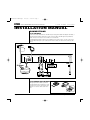
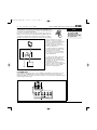
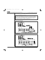
DTNR-manual-FINAL-dupe
11/10/03
9:45 AM
Page 1
DTNR
DIGITAL DUAL TUNER
INSTALLATION MANUAL AND USERS GUIDE
THE
LOGICAL
CHOICE
FOR
MULTIROOM
SYSTEMS
DTNR-manual-FINAL-dupe
11/10/03
9:45 AM
Page 1
DTNR USER’S GUIDE AND INSTALLATION MANUAL
ELAN
HOME
SYSTEMS
IMPORTANT SAFETY INSTRUCTIONS
CAUTION: TO REDUCE THE RISK OF ELECTRIC SHOCK, DO NOT REMOVE
COVER (OR BACK). NO USER-SERVICEABLE PARTS INSIDE. REFER
SERVICING TO QUALIFIED SERVICE PERSONNEL.
The lightning flash with arrowhead symbol, within an equilateral triangle, is intended
to alert the user to the presence of uninsulated "dangerous voltage" within the
product’s enclosure that may be of sufficient magnitude to constitute a risk of
electric shock to persons.
The exclamation point within an equilateral triangle is intended to alert the user to
the presence of important operating and maintenance (servicing) instructions in the
literature accompanying the appliance.
WARNING: TO PREVENT FIRE OR SHOCK HAZARD, DO NOT EXPOSE THIS
APPLIANCE TO RAIN OR MOISTURE.
For U.S.A.
This equipment has been tested and found to comply with the limits for a Class B digital device,
pursuant to Part 15 of the FCC Rules. These limits are designed to provide reasonable protection
against harmful interference in a residential installation. This equipment generates, uses, and can
radiate radio frequency energy and, if not installed and used in accordance with the instructions,
may cause harmful interference to radio communications. However, there is no guarantee that
interference will not occur in a particular installation. If this equipment does cause harmful
interference to radio or television reception, which can be determined by turning the equipment off
and on, the user is encouraged to try to correct the interference by one or more of the following
measures:
• Reorient or relocate the equipment and/or the receiving antenna.
• Increase the separation between the equipment and receiver.
• Connect the equipment into an outlet on a circuit different from that to which the receiver is
connected.
• Consult the dealer or an experienced radio/TV technician for help.
CAUTION
Changes or modifications to this equipment not expressly approved by the manufacturer for
compliance will void the manufacturer's warranty.
CAUTION
• DO NOT REMOVE THE PROTECTIVE HOUSING USING SCREWDRIVER.
• IF THIS PRODUCT DEVELOPS TROUBLE, CALL YOUR AUTHORIZED ELAN DEALER, AND
DO NOT USE THE PRODUCT IN A TROUBLED STATE.
Important Safety Instructions
1) Read these instructions.
2) Keep these instructions.
3) Heed all warnings.
4) Follow all instructions.
5) Do not use this apparatus near water.
6) Clean only with dry cloth.
7) Do not block any ventilation openings. Install in accordance with manufacturer’s instructions.
8) Do not install near any heat sources such as radiators, heat registers, stoves, or other
apparatus (including amplifiers) that produce heat.
9) Do not defeat the safety purpose of the polarized or grounding-type plug. A polarized plug
has two blades with one wider than the other. A grounding type plug has two blades and a
third grounding prong. The wide blade or the third prong are provided for your safety. If the
provided plug does not fit into your outlet, consult an electrician for replacement of the
obsolete outlet.
Page i
© ELAN Home Systems 2003 • All rights reserved. 11/03
DTNR-manual-FINAL-dupe
ELAN
11/10/03
HOME
9:45 AM
Page 2
SYSTEMS
USER’S GUIDE AND INSTALLATION MANUAL
DTNR
10) Protect the power cord from being walked on or pinched particularly at plugs, convenience
receptacles, and the point where they exit from the apparatus.
11) Only use attachments/accessories specified by the manufacturer.
12) Use only with the cart, stand, tripod, bracket, or table specified by the manufacturer, or sold
with the apparatus. When a cart is used, use caution when moving the cart/apparatus
combination to avoid injury from tip-over.
13) Unplug this apparatus during lightning storms or when unused for long periods of time.
14) Refer all servicing to qualified service personnel. Servicing is required when the apparatus
has been damaged in any way, such as power-supply cord or plug is damaged, liquid has
been spilled or objects have fallen into the apparatus, the apparatus has been exposed to
rain or moisture, does not operate normally, or has been dropped.
Do not expose this apparatus to drips or splashes.
Do not place any objects filled with liquids, such as vases, on the apparatus.
Do not install this apparatus in a confined space such as a book case or similar unit.
The apparatus draws nominal non-operating power from the AC outlet with its POWER switch in
the off position.
For CANADA
AC POWER CORD CONNECTION
CAUTION: TO PREVENT ELECTRIC SHOCK, MATCH WIDE BLADE OF PLUG TO WIDE
SLOT, FULLY INSERT.
Pour le CANADA
CORDE DE CONNEXION CA
ATTENTION: POUR ÉVITER LES CHOCS ÉLECTRIQUES, INTRODUIRE LA LAME LA
PLUS LARGE DE LA FICHE DANS LA BORNE CORRESPONDANTE DE LA PRISE ET
POUSSER JUSQU’AU FOND.
BEFORE USE
Read this before installation or operation
• Choose the installation location of your unit carefully. Avoid placing it in direct sunlight or
close to a source of heat. Also avoid locations subject to vibrations and excessive dust,
heat, cold or moisture.
•
Do not open the cabinet as this might result in damage to the circuitry or electrical shock. If
a foreign object should get into the set, contact your dealer.
•
When removing the power plug from the wall outlet, always pull directly on the plug, never
yank the cord.
•
Do not attempt to clean the unit with chemical solvents as this might damage the finish. Use
a clean, dry cloth.
•
Keep this manual in a safe place for future reference.
Maintenance
If the surface of the unit gets dirty, wipe with a soft cloth or use diluted mild soap liquid. Be sure to
remove any excess completely. Do not use thinner, benzene or alcohol as they may damage the
surface of the unit.
CAUTION
The product shall not be exposed to dripping or splashing and that no object filled with liquids,
such as vases, shall be placed on the product.
Do not install this equipment in a confined space such as a book case or similar unit.
© ELAN Home Systems 2003 • All rights reserved. 11/03
Page ii
DTNR-manual-FINAL-dupe
11/10/03
9:45 AM
Page 1
DTNR USER’S GUIDE AND INSTALLATION MANUAL
ELAN
HOME
SYSTEMS
TABLE OF CONTENTS
USERS GUIDE
Important Safety Instructions ............................................................................................i
Before Use........................................................................................................................ii
Congratulations and Thank You ......................................................................................2
Introduction ......................................................................................................................2
Controlling the DTNR Using VIA! Touch Panels ..........................................................3-5
IR Control ..................................................................................................3
RS232 Control............................................................................................4
Controlling the DTNR Using ELAN Keypads ..................................................................6
Front Panel & Remote Control Operation ........................................................................7
INSTALLATION MANUAL
Connections ................................................................................................................9-13
FM Antenna................................................................................................9
AM Antenna ..............................................................................................9
Audio Out ................................................................................................10
IR ....................................................................................................11-12
RS232 ......................................................................................................13
Power Cord ..............................................................................................13
System Control ................................................................................................14
Programming ELAN Keypads ................................................................14
VIA! Touch Panel Control the the DTNR ..........................................14-17
IR ....................................................................................14-15
RS232 ............................................................................16-17
RS232 Protocol ..........................................................................................18-19
Specifications ..................................................................................................19
Limited Warranty ..............................................................................................20
Page 1
© ELAN Home Systems 2003 • All rights reserved. 11/03
DTNR-manual-FINAL-dupe
ELAN
11/10/03
HOME
9:45 AM
Page 2
SYSTEMS
USER’S GUIDE AND INSTALLATION MANUAL
DTNR
CONGRATULATIONS AND THANK YOU
You have purchased the highest quality IR/RS232-controllable Digital Dual Tuner on the market
today – the ELAN DTNR. Please read this manual carefully. It will help you to fully understand
the operation of your dual tuner.
ELAN Home Systems designs and manufactures the industry’s most complete line of multi-room
audio/video systems and components. For free product information, visit our web site,
www.elanhomesystems.com, or write or e-mail us at:
ELAN Home Systems Product Information
2428 Palumbo Dr.
Lexington, KY 40509
e-mail: [email protected]
Look for these other award-winning ELAN products:
• VIA!dj™ Digital Music Server
• VIA!® Touch Panel
• System6™ Integrated Multi-Zone Controller
• D1200 12-Channel Digital Power Amplifier
• M Series™ In-Wall and In-Ceiling Speakers
INTRODUCTION
The ELAN DTNR Digital Dual Tuner is two FM/AM digital tuners in one standard-sized audio
component. Each tuner has its own audio output so that each may be listened to independently.
The DTNR features Direct Access tuning, enabling you to go directly to a radio station by entering
its frequency number (for example, to go to 102.7, simply enter 1027 and you’re there). The
DTNR also features a total of 120 station presets – 30 FM and 30 AM presets per tuner. When
used in conjunction with ELAN VIA! Touch Panels, the combination of Direct Access tuning and a
plethora of Presets makes control of the DTNR easy and intuitive – from anywhere in your home.
This user’s manual is broken up into sections, each describing different means of controlling your
DTNR. Since the DTNR can be controlled in a variety of ways, it is important that you speak with
your ELAN installer and have them explain to you how they have the unit connected to your
ELAN system.
If your DTNR is not connected to an ELAN system, you can go directly to the last section
describing Front Panel and Remote Control use.
© ELAN Home Systems 2003 • All rights reserved. 11/03
Page 2
DTNR-manual-FINAL-dupe
11/10/03
9:45 AM
Page 3
DTNR USER’S GUIDE AND INSTALLATION MANUAL
ELAN
HOME
SYSTEMS
CONTROLLING THE DTNR USING
VIA! TOUCH PANELS
First, you will need to know if your
DTNR is being controlled via IR
signals or RS232 serial
communications. This can easily be
determined by seeing if there is a
2-way ‘Message Center’ displayed on
your VIA! Touch Panels.
If there is, your DTNR is being
controlled with RS232 serial
communications and you can proceed
to the section entitled RS232
Control (Page 4).
If you do not see the Message Center
your DTNR is being controlled with IR
signals and you should refer to the
following section entitled IR Control.
Two-Way Message Center
NOTE:
VIA! Touch Panels can be configured in many ways. The layouts shown herein are the
factory-default control screens. Your ELAN installer/programmer may have added, deleted or
moved any number of buttons depending on your needs and/or input. Also note that the
‘motif’ that is shown (Silky Blue) is just one of many styles available and your VIA! Touch
Panels may look quite different than the ones depicted here.
IR CONTROL
1
The FAVORITES Screen
1. FAV1 thru FAV15
Takes you directly
to the Preset
stations you have
programmed in
memory. Buttons
can be renamed to
reflect a station’s
frequency (i.e.
102.7) or call
letters (i.e.
WNEW).
2. NEXT
2
Takes you to the
DIRECT screen
(see Page 4)
3. STEP
/
In PRESET mode:
The STEP button is used to step through the
preset stations you have programmed in memory.
3
In DIRECT mode:
Use to search Up or Down through the band (AM or FM) selected. Hold down the STEP button
for 0.5 to 2 seconds to begin search. When a station is tuned in, the tuning process will stop
automatically.
Page 3
© ELAN Home Systems 2003 • All rights reserved. 11/03
DTNR-manual-FINAL-dupe
ELAN
11/10/03
HOME
9:45 AM
Page 4
USER’S GUIDE AND INSTALLATION MANUAL
SYSTEMS
The DIRECT Screen
4. 0-9
In PRESET mode:
Selects a station that has been
stored in memory, i.e.
01 = PRESET 1,
30 = PRESET 30, etc.
DTNR
4
5
In DIRECT mode:
Use 0-9 to enter a station’s
frequency, i.e. 899 = 89.9,
1027 = 102.7
6
7
5. AM
8
Selects the AM band.
6. FM
Selects the FM band.
7. FM MODE
Switches the FM signal between
stereo and mono. Switching to
mono mode can make weak
FM signals sound clearer.
11
10
9
8. FAV
Takes you to the FAVORITES screen (see Page 3)
9. PRESET
Places the DTNR into PRESET mode.
10. STEP
/
In PRESET mode: The STEP button is used to step through the preset stations you have
programmed in memory.
In DIRECT mode: The STEP button is used to search Up or Down through the band (AM or
FM) selected. Hold down the STEP button for 0.5 to 2 seconds to begin search. When a
station is tuned in, the tuning process will stop automatically.
11. DIRECT
Places the DTNR into DIRECT mode.
RS232 CONTROL
1
As explained at the beginning of
this section, VIA! Touch Panels
can be configured in many ways.
These example screens show the
factory-default layouts with the
Silky Blue ‘motif’.
2
The FAVORITES Screen
1.
MESSAGE CENTER
3
Displays important user
feedback such as station
selected, Band (AM/FM),
Stereo/Mono, Direct/Preset
modes.
2.
NEXT
Takes you to the DIRECT screen
(see Page 5)
3.
4
FAV1-FAV16
Selects preset stations 1-16. Buttons can be renamed to reflect a station’s frequency (i.e.
102.7) or call letters (i.e. WNEW). Additional Presets can be accessed from the DIRECT
screen (see Page 5).
© ELAN Home Systems 2003 • All rights reserved. 11/03
Page 4
DTNR-manual-FINAL-dupe
11/10/03
9:45 AM
Page 5
DTNR USER’S GUIDE AND INSTALLATION MANUAL
4.
STEP
ELAN
HOME
SYSTEMS
/
In PRESET mode: The STEP button is used to step through the preset stations you have
programmed in memory. Press and hold to scan through the presets.
In DIRECT mode: The STEP button is used to search Up or Down through the band (AM or
FM) selected. Press the STEP button to begin search. When a station is tuned in, the tuning
process will stop automatically.
The DIRECT Screen
5
5. MESSAGE CENTER
6. FAV
Takes you to the
FAVORITES screen.
6
7. AM
7
Selects the AM band.
8
8. FM
Selects the FM band.
9
9. FM MODE
10
Switches the FM
signal between
stereo and mono.
13
14
Switching to mono
mode can make weak FM signals sound clearer.
12
11
10. MEMORY
Press to store a station into the DTNR’s memory (see Storing Presets, below)
11. STEP
/
In PRESET mode the STEP button is used to step through the preset stations you have
programmed in memory.
In DIRECT mode the DIRECT button is used to search Up or Down through the band (AM
or FM) selected. Press the STEP button to begin search. When a station is tuned in, the
tuning process will stop automatically.
12. PRESET
Places the DTNR into PRESET mode.
13. DIRECT
Places the DTNR into DIRECT mode.
14. 0-9
In PRESET mode, the numeric buttons will allow you to access Preset stations 1-30 by
entering the appropriate two-digit number, i.e. Preset 1 = 01, Preset 30 = 30. There are 60
Presets available per tuner – 30 FM presets and 30 AM presets.
In DIRECT mode, the numeric buttons will allow you to directly access a station by entering
its frequency, i.e. 1063 = 106.3.
STORING PRESETS FROM A VIA! TOUCH PANEL (RS232 only)
Page 5
•
Up to 30 FM and 30 AM presets can be stored in the DTNR’s memory for each tuner. That’s
a total of 120 presets – 60 for TUNER1 and 60 for TUNER2.
•
Up to 16 presets per tuner can be accessed from the favorites screen on the VIA! Touch Panel.
•
All 120 presets can be accessed from the DIRECT screen by entering the two-digit preset
number.
© ELAN Home Systems 2003 • All rights reserved. 11/03
DTNR-manual-FINAL-dupe
ELAN
11/10/03
HOME
9:45 AM
Page 6
USER’S GUIDE AND INSTALLATION MANUAL
SYSTEMS
DTNR
To enter a PRESET into the DTNR’s memory:
1. Select the AM or the FM band by pressing the corresponding button.
2. Press the DIRECT button to select the manual tuning mode.
3. Select the station you want to listen to by pressing the STEP button or the numeric
buttons.
4. Press the MEMORY button. You will see Memory displayed in the VIA!’s Message Center.
5. Enter the two-digit preset number you wish to store the station under. You will see the
number displayed in the VIA!’s Message Center.
6. To store more stations, repeat steps 3 thru 5.
CONTROLLING THE DTNR USING ELAN KEYPADS
Your DTNR can also be controlled from ELAN keypads. It is up to your ELAN
installer/programmer to assign DTNR commands to each keypad button, and it is important that
you consult with them so that you know which button performs which command. As a rule of
thumb, it is best to keep the commands as user-friendly as possible since, unlike VIA! Touch
Panels, there are no messages displayed on a keypad to inform you of the DTNR’s status.
Generally, the following commands might be assigned to these buttons:
COMMAND
Tune/Preset Up/Down
Direct/Preset Select
KEYPAD BUTTON
/
or <<I >>I
Control
0-9
Make sure to consult you ELAN installer/programmer for detailed button/function information.
ELAN Z100/Z150 Keypads
© ELAN Home Systems 2003 • All rights reserved. 11/03
ELAN Z250 Keypad
Page 6
DTNR-manual-FINAL-dupe
11/10/03
9:45 AM
Page 7
DTNR USER’S GUIDE AND INSTALLATION MANUAL
ELAN
HOME
SYSTEMS
FRONT PANEL & REMOTE CONTROL OPERATION
Function Names
A. REMOTE SENSOR
Receives IR information from infrared emitters and the remote control.
B. STANDBY indicator
This LED is lit when the unit is in the standby mode. When the unit is
turned on, the LED goes off.
C. POWER switch
Press this to switch the unit between ON and STANDBY. The equipment
draws nominal non-operating power from the AC outlet when it is in
STANDBY mode.
D. FM button, AM button
Use these buttons to select either FM or AM.
E. FM MODE button
Use this button to select either FM stereo or FM monaural reception.
F. PRESET button
Use this button to select the Preset Tuning Mode. In Preset Mode, the
numeric buttons on the remote control or front panel can be used to
directly access preset stations that have been stored in the DTNR’s
memory.
G. DIRECT button
Use this button to select the Manual Tuning Mode. In Manual Tuning
Mode, the numeric buttons on the remote control or front panel can be
used to directly input the frequency numbers of radio stations.
H. MEMORY button
Use this button to store preset stations into memory.
I.
TUNING/PRESET buttons
Use these buttons to tune in a station.
J. Numeric buttons
These buttons are used either to input frequency numbers or to select
preset stations.
K. LCD Display
Page 7
© ELAN Home Systems 2003 • All rights reserved. 11/03
DTNR-manual-FINAL-dupe
ELAN
11/10/03
HOME
9:45 AM
Page 8
SYSTEMS
USER’S GUIDE AND INSTALLATION MANUAL
DTNR
CONTROLLING THE DTNR FROM
THE FRONT PANEL & REMOTE CONTROL
AUTO SELECTION
• Hold down the TUNING/PRESET button for 0.5 to 2 seconds.
• When a station is tuned in, the tuning process will stop automatically.
• If you want to stop the tuning process, press the TUNING/PRESET button again.
MANUAL SELECTION
• When the TUNING/PRESET button is pressed momentarily (0.5 second or less), the frequency
changes by a fixed step.
FM : 0.2 MHz steps
AM : 10 kHz steps
• Press the TUNING/PRESET button repeatedly until the station you want to listen to is found.
PRESET SELECTION
• Press PRESET.
Preset stations can be selected by either:
1. Input the PRESET number using the numeric buttons. This must be a 2-digit number, i.e.
enter 01 to go to preset 1, enter 30 to go to preset 30.
2. After pressing PRESET, use the TUNING/PRESET up or down buttons to sequentially
access each preset.
When no button is pressed for 3 seconds, Preset mode will be cancelled.
DIRECT TUNING
• Press the DIRECT button to select the manual tuning mode.
• Input the frequency numbers with the numeric buttons.
Example:
• To select FM 88.3 MHz enter 8 8 3
• To select AM 1220 kHz enter 1 2 2 0
When no button is pressed for 3 seconds, Direct Tuning mode will be cancelled.
FM MODE BUTTON
Pressing this button alternates between FM Stereo mode and FM Mono mode.
• Stereo: FM stereo broadcasts are received in stereo and the "STEREO" indicator lights
in the display.
• Mono: To compensate for weak FM stereo reception, select this mode. Reception will
now be forced monaural, reducing unwanted noise.
PRESET TUNING
Up to 30 FM and 30 AM presets can be stored in the DTNR’s memory for each tuner. That’s a
total of 120 presets – 60 for TUNER1 and 60 for TUNER2.
To enter a PRESET into the DTNR’s memory:
1. Select the AM or the FM band by pressing the corresponding button.
2. Press the DIRECT button to select the manual tuning mode.
3. Select the station you want to listen to by pressing the STEP (TUNING/PRESET) button or
the numeric buttons.
4. Press the MEMORY button.
5. While the "MEMORY" indicator is blinking, enter a two-digit preset number to store the
station in memory. You can also select a preset channel by using the TUNING/PRESET
buttons, and then pressing the MEMORY button.
6. To store more stations, repeat steps 3 to 5.
To select PRESET stations:
1. Select the AM or the FM band by pressing the corresponding button.
2. Press the PRESET button.
3. Select a preset channel using the numeric buttons, or press the (STEP) TUNING/PRESET
button repeatedly until the desired preset station is found
MEMORY BACKUP
Settings are stored permanently, even when power is turned off and the unit is unplugged.
© ELAN Home Systems 2003 • All rights reserved. 11/03
Page 8
DTNR-manual-FINAL-dupe
11/10/03
9:45 AM
Page 9
DTNR USER’S GUIDE AND INSTALLATION MANUAL
ELAN
HOME
SYSTEMS
INSTALLATION MANUAL
CONNECTIONS
A. FM ANTENNA
Connect an outdoor FM antenna to the FM 75Ω jack using the included 75Ω adaptor. Generally, a
3-element antenna will be sufficient; if you live in an area where the FM signals are particularly
weak, it may be necessary to use one with 5 or more elements.
If standard FM broadcast frequencies are available via your cable service, you may connect your
75 ohm FM antenna jack to your cable system. Please contact your cable service to discuss this
option.
B. AM INDOOR LOOP ANTENNA
1
2
The high-performance AM loop antenna
provided with this unit is sufficient for good
reception in most areas. To stand the loop
antenna on a surface, fix the claw to the
slot.
Page 9
© ELAN Home Systems 2003 • All rights reserved. 11/03
DTNR-manual-FINAL-dupe
ELAN
11/10/03
HOME
9:45 AM
Page 10
USER’S GUIDE AND INSTALLATION MANUAL
SYSTEMS
How to Connect
The AM antenna is connected to the terminals marked AM/GND. These
connections are not polarity sensitive, so it does not matter which wire is
connected to the GND or AM terminals.
Press the lever, insert the end of the wire, and then release the lever.
Make sure it is fastened securely by pulling the wire lightly. Make sure
only the bare, stripped wire is inserted in the jack and that no plastic
insulation is preventing contact between the antenna wire and terminal.
DTNR
NOTE:
Even when using
an outdoor AM
antenna, do not
disconnect the AM
loop antenna.
Place the antenna on a shelf, for
example, or hang it on a window
frame, etc., in the direction which gives
the best reception, as far away as
possible from the entire system,
speaker cords and the power cord, to
prevent unwanted noise.
If the AM loop antenna provided does
not deliver sufficient reception (often
due to being too far from the
transmitter or in a concrete building,
etc.), it may be necessary to use an
outdoor AM antenna
Use either a high quality commercial
AM antenna or, if not available, an
insulated wire more than 15 ft (5 m)
long, strip one end, and connect this to
the terminal as shown.
The antenna wire should be strung
outdoors or indoors near a window. For
better reception, connect the GND
terminal to a reliable ground.
C. AUDIO OUT
Using RCA-type interconnect cables, connect TUNER 1 and TUNER 2 audio outputs to any two
pairs of inputs on an ELAN preamp controller (e.g.System6, Z•630 or HD Series Input Card
(HDC1020)). Make sure to connect Left channel outputs to Left channel inputs and Right channel
outputs to Right channel inputs.
© ELAN Home Systems 2003 • All rights reserved. 11/03
Page 10
DTNR-manual-FINAL-dupe
11/10/03
9:45 AM
Page 11
DTNR USER’S GUIDE AND INSTALLATION MANUAL
ELAN
HOME
SYSTEMS
D. IR
There are multiple ways to control the DTNR via IR using either the 3.5mm (‘mini’) IR jack on the
back panel or the IR SENSOR on the front panel.
NOTE: There are two distinct sets of IR codes for the DTNR, one set for Tuner 1 and another
set for Tuner 2. From an ELAN multi-room controller, these distinct IR codes are outputted
from the Source-Specific IR output ports and the IR "ALL" port. If using the Source-Specific IR
Output ports, remember that the IR Output port number corresponds to the Source Input
number, e.g. if Tuner 1 is connected to Source Input 1, the IR information for Tuner 1 will be
sent out IR port 1 and the ALL port. If Tuner 2 is connected to Source Input 2, the IR
information for Tuner 2 will be sent out IR port 2 and the ALL port.
Rear Panel ‘IR’ Jack Connections
Using Source-Specific IR Output Ports
Using the IR "ALL" Port
Page 11
© ELAN Home Systems 2003 • All rights reserved. 11/03
DTNR-manual-FINAL-dupe
ELAN
11/10/03
HOME
9:45 AM
Page 12
SYSTEMS
USER’S GUIDE AND INSTALLATION MANUAL
DTNR
Front Panel IR Sensor Connections
Using Source-Specific IR Output Ports
Using the IR "ALL" Port
© ELAN Home Systems 2003 • All rights reserved. 11/03
Page 12
DTNR-manual-FINAL-dupe
11/10/03
9:45 AM
Page 13
DTNR USER’S GUIDE AND INSTALLATION MANUAL
ELAN
HOME
SYSTEMS
E. RS-232
When connected to an ELAN SC4 System Controller the DTNR will be controlled using RS232
Serial Communications and will provide detailed user feedback to all ELAN VIA! Touch Panels in
the system. The RS232 port on the back of the DTNR can also be used to connect the DTNR to
other RS-232 controllers.
If connecting the DTNR to SC4 ports 3 or 4 a Null Modem ‘gender bender’ must be used.
F. Power Cord (AC)
Be sure to connect the power
cord to an AC outlet which
supplies the correct voltage.
Hold the power plug, not the
cord, when plugging or
unplugging the unit.
G. Rack Ears
(included)
RACK MOUNT ANGLE KIT
1. Remove the screws and
washers from each side of the
TR-D2000.
2. Using the provided screws,
attach the mount angles to the
TR-D2000. (L: left, R: right)
Contents: Rack Mount Angle x2, Mount Angle Attaching Screw x8, Rack Mount Screw w/two
washers x4
L
Page 13
© ELAN Home Systems 2003 • All rights reserved. 11/03
DTNR-manual-FINAL-dupe
ELAN
11/10/03
HOME
9:45 AM
Page 14
USER’S GUIDE AND INSTALLATION MANUAL
SYSTEMS
DTNR
ELAN SYSTEM CONTROL OF THE DTNR
The DTNR can be controlled using ELAN keypads and/or VIA!® Touch Panels. Refer to the
User’s Guide sections of this manual for detailed information on the operation of the DTNR with
these interfaces.
PROGRAMMING ELAN KEYPADS TO CONTROL THE DTNR
ELAN Z100/Z150 Keypads
ELAN Z250 Keypad
The IR commands for the DTNR need to be downloaded into ELAN keypads. This can be
accomplished by:
1. Using the included handheld remote control and the Z090 Keypad Programming Module to
‘teach’ the keypads. Consult the ELAN Z090 Programming Manual for details.
2. Using VIATOOLS 4.1 (or higher) and the VIA! Learner, in conjunction with a PC or laptop, to
download DTNR commands into ELAN keypads. VIATOOLS 4.1 (or higher) contains separate
IR libraries for Tuner1 and Tuner2. Consult the VIATOOLS Reference Manual for details.
When using ELAN keypads to control the DTNR we recommend that you keep the functions as
user-friendly as possible. This may mean making certain functions (such as Memory storage and
FM MODE) available only at the tuner itself and not at the keypads. The table below shows
examples of where DTNR IR commands might be learned to ELAN keypad buttons:
DTNR IR COMMAND
Tune/Preset up/down
Direct/Preset numeric select
Direct access mode
Preset mode
FM
AM
Most listened-to station
2nd most listened to station
Z100/Z150
CNTL up/down
0-9
PLAY
STOP
FM/AM
FM/AM
FAV
*FAV
Z200Z250
|<< >>|
0-9 (Z250 only)
PLAY
STOP
FM (optional keycap)
FM (optional keycap)
FAVORITE
*FAVORITE
VIA! TOUCH PANEL CONTROL OF THE DTNR
The DTNR can be controlled from a VIA! Touch Panel using either IR or RS232 serial commands.
This section explains in brief the setup procedures for both options. Complete programming
details can be found in the VIATOOLS 4.1 Reference Manual.
IR Control
VIA!TOOLS 4.1 (or higher) has preconfigured templates for both TUNER1 and TUNER 2. Each
template has two pages: a FAV page where you can enter the call letters (e.g. WBGO), station
number (e.g. 102.7) or music type (JAZZ) for 15 station presets, and a DIRECT page for direct
© ELAN Home Systems 2003 • All rights reserved. 11/03
Page 14
DTNR-manual-FINAL-dupe
11/10/03
9:45 AM
Page 15
DTNR USER’S GUIDE AND INSTALLATION MANUAL
ELAN
HOME
SYSTEMS
access control. These templates are automatically imported with IR commands assigned to each
button when you add the DTNR source button from the Special Components option in VIATOOLS.
The FAVORITES Page
The DIRECT ACCESS Page
(Silky Blue motif shown – many other motifs are available)
The FAV1 thru FAV15 buttons are factory defaulted with the following sequence of IR commands:
1. PRESET (places the DTNR into Preset mode)
2. FM (selects the FM band)
3. PRESET number (e.g. FAV1=Preset 01, FAV2=Preset 02, etc.).
These sequences can be easily modified with VIATOOLS setup software should you, for example,
wish to change the FM band command to AM for accessing an AM preset.
Should you wish to create you own tuner pages for the VIA!, all of the IR commands for DTNR1
and DTNR2 are located in VIA!TOOLS IR Library.
For detailed VIA! Touch Panel programming information refer to the VIA!TOOLS 4.1 Reference Manual or
VIA!TOOLS Help files.
Page 15
© ELAN Home Systems 2003 • All rights reserved. 11/03
DTNR-manual-FINAL-dupe
ELAN
11/10/03
HOME
9:45 AM
Page 16
SYSTEMS
USER’S GUIDE AND INSTALLATION MANUAL
DTNR
Serial Control
The DTNR is also a two-way RS232 serially-controlled device. If using an ELAN SC-4 System
Controller to control the DTNR, pre-written serial drivers are available in VIATOOLS 4.1 (or
higher).
To add the DTNR 2-way serial driver:
1. From the SYSTEM screen select SC-4 under System Components.
2. From the SC-4 screen select the Com Port you wish to use and click on Add/Remove.
3. From the SC-4 Serial Device Add/Delete screen select Two-Way Drivers.
4. From the Add Device to Port screen select Dual Tuner.
5. From the Layout screen, select Add/Remove/Save, then Two-Way Component,
then Dual Tuner.
For detailed VIA! Touch Panel programming information refer to the
VIA!TOOLS 4.1 Reference Manual or VIA!TOOLS Help files.
Pre-configured Templates
Pre-configured templates for Tuner 1 and Tuner 2, with serial
commands already loaded under each button, are automatically imported. Each template has two
pages: a FAV page where you can enter the call letters (e.g. WBGO), station number (e.g. 102.7)
or music type (JAZZ) for 16 station presets, and a DIRECT page for direct access and mode
control.
The FAV1 thru FAV16 buttons are factory defaulted with the following serial commands: PRESET
(places the DTNR into Preset mode), FM (selects the FM band), and the PRESET number (e.g.
FAV1=Preset 1, FAV2=Preset 2, etc.). These sequences can be easily modified with VIATOOLS
setup software should you, for example, wish to change the FM band command to AM for
accessing an AM preset.
As shown on the following page, two-way serial control of the DTNR provides the end user with
real-time on-screen feedback of all DTNR functions.
© ELAN Home Systems 2003 • All rights reserved. 11/03
Page 16
DTNR-manual-FINAL-dupe
11/10/03
9:45 AM
Page 17
DTNR USER’S GUIDE AND INSTALLATION MANUAL
ELAN
HOME
SYSTEMS
The FAVORITES Page
The DIRECT ACCESS Page
(Silky Blue motif shown – many other motifs are available)
For detailed VIA! Touch Panel programming information refer to the VIA!TOOLS 4.1 Reference Manual
or VIA!TOOLS Help files.
Page 17
© ELAN Home Systems 2003 • All rights reserved. 11/03
DTNR-manual-FINAL-dupe
ELAN
11/10/03
HOME
9:45 AM
Page 18
USER’S GUIDE AND INSTALLATION MANUAL
SYSTEMS
DTNR
RS232 PROTOCOL
Connecting the DTNR to an External RS232 Controller
INTERFACE
A DB9 DSUB connector is used for connection.
Female Connector
Pin 2: Transmission Output
Pin 3: Reception Input
Pin 5: GND
SERIAL CONTROL
Port Settings:
Baud Rate
Stop Bits
Parity
Byte Size
19200
1
None
8
Command Structure:
Tuner
T1 or T2
Band
Parameters
B1 = AM or B2 = FM See below
Carriage Return
HEX 0x0d or DEC 13
Parameters:
Parameter
Description
A
B
F
L
M
N
P
Q
Seek UP = A1 or Seek Down = A0
AM = B1 or FM = B2
Frequency: FXXXX
where X = 0 thru 9
Sets Presets = LXX where XX = 01 thru 30
Step UP = M1 or Seek Down = M0
Preset Up = N1 and Preset Down = N0
30 Presets: P01 to P30 P00: No Preset selected.
Queries tuner.
Q1 = query Tuner 1. Response = T1 BX PXX FXXXX SXX
Q2 = query Tuner 2. Response = T2 BX PXX FXXXX SXX
Q3 = query Tuner 1 & 2 Response =
T1 BX PXX FXXXX SXX T2 BX PXX FXXXX SXX
S
T
X
Note: If tuner is off the response will be: X0
Signal Lock SXX 1 = Locked and 0 = NOT
Stereo Presense SXX 1 = Stereo and 0 = Mono
S00 = no signal, no stereo
S01 = invalid
S10 = signal lock, mono
S11 = signal lock, stereo
Tuner 1 = T1 or Tuner 2 = T2
Power Command X1 = ON and X2 = OFF
© ELAN Home Systems 2003 • All rights reserved. 11/03
Page 18
DTNR-manual-FINAL-dupe
11/10/03
9:45 AM
Page 19
DTNR USER’S GUIDE AND INSTALLATION MANUAL
ELAN
HOME
SYSTEMS
Command Structure 1 Examples:
String
T1B2F1063<cr>
T2B1F1550<cr>
T1B1A0<cr>
T2B2A1<cr>
T1B1M0<cr>
T2B2P02
T1B2S11
T2B2M1<cr>
T1B2F0971L02<cr>
Q1<cr>
Result
Set Tuner 1 to FM Band Station 106.3.
Set Tuner 2 to AM Band Station 1550.
Set Tuner 1 to AM Band and Seek the Frequency down.
Set Tuner 2 to FM Band and Seek the Frequency up.
Set Tuner 1 to AM Band and Step the Frequency down.
Set Tuner 2 to FM Band Preset 02
Set Tuner 1 to FM Band with Signal Lock and Stereo Mode
Set Tuner 2 to FM Band and Step the Frequency up.
Set Tuner 1 Preset 02 to FM Band Frequency 97.1.
Query Tuner 1: T1B2P00F1067S00 Tuner 1 is in FM mode, no preset
selected. The frequency is 106.7 with no signal and no stereo
Shortcut Commands:
String
T1L15<cr>
T1A0<cr>
T2M1<cr>
T1N1<cr>
T2N0<cr>
T1M1<cr>
T1B1<cr>
Result
Set Tuner 1 to Preset 15
Seek Tuner 1 Down
Step Tuner 2 Up
Step Tuner 1 to the next preset
Step Tuner 2 to the previous preset
Step Tuner 1 frequency up by 0.2 MHz
Set Tuner 1 to AM mode and tune to the last previously tuned
AM station
SPECIFICATIONS
Tuner Section (Without notes 98.1 MHz, 65 dBf)
FM Tuning Range . . . . . . . . . . . . . . . . . . . . . . . . . . . . 87.5 MHz – 107.9 MHz (200 kHz steps)
AM Tuning Range . . . . . . . . . . . . . . . . . . . . . .. . . . . . . . . . . 530 kHz – 1,710 kHz (10 kHz steps)
Frequency Response. . . . . . . . . . . . . . . . . . . . . . . . . . . . . . . . . . . . . .30 Hz – 15 kHz, ±1.5 dB
General
Power requirements . . . . . . . . . . . . . . . . . . . . . . . . . . . . . . . . . . . . . . . . . . . . 120 V AC, 60 Hz
Power Consumption . . . . . . . . . . . . . . . . . . . . . . . . . . . . . . . . . . . . . . . . . . . . . . . . . . . . . .12 W
Dimensions (W x H x D) . . . . . . . . . . . . . . . . . . . . . . . . . . . . . . . . . . . . . . . 435 x 95 x 270 mm
(17-1/8" x 3-3/4" x 10-5/8")
Weight (net) . . . . . . . . . . . . . . . . . . . . . . . . . . . . . . . . . . . . . . . . . . . . . . . . . 4 kg (8-13/16 lbs)
Standard Accessories . . . . . . . . . . . . . . . . . . . . . . . . . . . . . . . . . . . . . Remote Control Unit x 1
Battery (AAA, R03, UM-4) x 2
AM Loop Antenna x 1
RCA Cord x 2
Rack Ears x 2
75Ω Adapter x 1
• Improvements may result in specifications and features changing without notice.
• Illustrations may differ slightly from production models.
Page 19
© ELAN Home Systems 2003 • All rights reserved. 11/03
DTNR-manual-FINAL-dupe
11/10/03
9:45 AM
Page 20
Limited Warranty
ELAN HOME SYSTEMS, L.L.C. ("ELAN") warrants the DTNR Digital Dual Tuner to be free from defects in materials and
workmanship for one (1) year from the date of purchase. If within the applicable warranty period above purchaser
discovers such item was not as warranted above and promptly notifies ELAN in writing, ELAN shall repair or replace the
items at the company's option. This warranty shall not apply (a) to equipment not manufactured by ELAN, (b) to
equipment which shall have been installed by other than an authorized ELAN installer, (c) to installed equipment which is
not installed to ELAN's specifications, (d) to equipment which shall have been repaired or altered by others than ELAN, (e)
to equipment which shall have been subjected to negligence, accident, or damage by circumstances beyond ELAN's
control, including, but not limited to, lightning, flood, electrical surge, tornado, earthquake, or any other catastrophic events
beyond ELAN's control, or to improper operation, maintenance or storage, or to other than normal use of service. With
respect to equipment sold by, but not manufactured by ELAN, the warranty obligations of ELAN shall in all respects
conform and be limited to the warranty actually extended to ELAN by its supplier. The foregoing warranties do not cover
reimbursement for labor, transportation, removal, installation, or other expenses which may be incurred in connection with
repair or replacement.
Except as may be expressly provided and authorized in writing by ELAN, ELAN shall not be subject to any other
obligations or liabilities whatsoever with respect to equipment manufactured by ELAN or services rendered by ELAN.
THE FOREGOING WARRANTIES ARE EXCLUSIVE AND IN LIEU OF ALL OTHER EXPRESSED AND IMPLIED
WARRANTIES EXCEPT WARRANTIES OF TITLE, INCLUDING BUT NOT LIMITED TO IMPLIED WARRANTIES OF
MERCHANTABILITY AND FITNESS FOR A PARTICULAR PURPOSE.
WARNING TO OUR VALUED CONSUMERS:
To insure that consumers obtain quality pre-sale and after-sale support and service, ELAN Home Systems™ products are
sold exclusively through authorized dealers. ELAN products are not sold online.
The warranties on ELAN products are NOT VALID if the products have been purchased from an unauthorized dealer or an
online E-tailer. To determine if your ELAN re-seller is authorized, please call ELAN Home Systems at (859)269-7760.
DTNR-manual-FINAL-dupe
11/10/03
9:45 AM
Page 21
© ELAN Home Systems 2003 • All rights reserved. 11/03 • Second Edition • P/N: 9900156 REVC