1
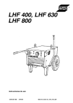
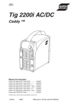
CaddyTig HF
Bruksanvisning
Brugsanvisning
Bruksanvisning
Käyttöohjeet
Instruction manual
Betriebsanweisung
Manuel d’instructions
0700 159 017
0219
Gebruiksaanwijzing
Instrucciones de uso
Istruzioni per l’uso
Manual de instruções
Ïäçãßåò ÷ñÞóåùò
Instrukcja obs³ugi
Valid from serial no. 217
SVENSKA . . . . . . . . . . . . . . . . . . . . . . . . . . . . . . . . . . . . . . . . . . . . . . . . . . . . .3
DANSK . . . . . . . . . . . . . . . . . . . . . . . . . . . . . . . . . . . . . . . . . . . . . . . . . . . . . . .13
NORSK . . . . . . . . . . . . . . . . . . . . . . . . . . . . . . . . . . . . . . . . . . . . . . . . . . . . . . .23
SUOMI . . . . . . . . . . . . . . . . . . . . . . . . . . . . . . . . . . . . . . . . . . . . . . . . . . . . . . .33
ENGLISH . . . . . . . . . . . . . . . . . . . . . . . . . . . . . . . . . . . . . . . . . . . . . . . . . . . . .43
DEUTSCH . . . . . . . . . . . . . . . . . . . . . . . . . . . . . . . . . . . . . . . . . . . . . . . . . . . .53
FRANÇAIS . . . . . . . . . . . . . . . . . . . . . . . . . . . . . . . . . . . . . . . . . . . . . . . . . . . .63
NEDERLANDS . . . . . . . . . . . . . . . . . . . . . . . . . . . . . . . . . . . . . . . . . . . . . . . . .73
ESPAÑOL
. . . . . . . . . . . . . . . . . . . . . . . . . . . . . . . . . . . . . . . . . . . . . . . . . . . .83
ITALIANO . . . . . . . . . . . . . . . . . . . . . . . . . . . . . . . . . . . . . . . . . . . . . . . . . . . . .93
PORTUGUÊS . . . . . . . . . . . . . . . . . . . . . . . . . . . . . . . . . . . . . . . . . . . . . . . . . .103
E
HNIKA . . . . . . . . . . . . . . . . . . . . . . . . . . . . . . . . . . . . . . . . . . . . . . . . . . . .113
POLSKI . . . . . . . . . . . . . . . . . . . . . . . . . . . . . . . . . . . . . . . . . . . . . . . . . . . . . .123
Schema - Skema - Skjema - Johdotuskaavio - Diagram - Schaltplan Schéma - Esquema - Schemat - . . . . . . . . . . . . . . . . . .133
Reservdelsförteckning - Reservedelsfortegnelse - Reservedeloversikt Varaosaluettelo - Spare parts list - Ersatzteilverzeichnis Liste de pièces détachées - Reserveonderdelenlijst Lista de repuestos - Esercizio - Lista de peças de reposição . . . . . . . . . . . . . . . . . . . . . . . . . . . . . . . . . . . . . . . . . . . . . . . . . . . . . . . . . . . . .135
2
1 DIRECTIVE . . . . . . . . . . . . . . . . . . . . . . . . . . . . . . . . . . . . . . . . . . . . . . . . . .44
2 SAFETY . . . . . . . . . . . . . . . . . . . . . . . . . . . . . . . . . . . . . . . . . . . . . . . . . . . . .44
3 INTRODUCTION . . . . . . . . . . . . . . . . . . . . . . . . . . . . . . . . . . . . . . . . . . . . .46
3.1 Technical data . . . . . . . . . . . . . . . . . . . . . . . . . . . . . . . . . . . . . . . . . . . .46
3.2 Equipment . . . . . . . . . . . . . . . . . . . . . . . . . . . . . . . . . . . . . . . . . . . . . . .47
3.3 Field of application . . . . . . . . . . . . . . . . . . . . . . . . . . . . . . . . . . . . . . . . .47
4 INSTALLATION . . . . . . . . . . . . . . . . . . . . . . . . . . . . . . . . . . . . . . . . . . . . . .47
4.1 Placing . . . . . . . . . . . . . . . . . . . . . . . . . . . . . . . . . . . . . . . . . . . . . . . . . .47
4.2 Connection . . . . . . . . . . . . . . . . . . . . . . . . . . . . . . . . . . . . . . . . . . . . . .47
4.2.1 Mains connection . . . . . . . . . . . . . . . . . . . . . . . . . . . . . . . . . . . . . . . . .47
4.2.2 Connection of welding and return cable in MMA . . . . . . . . . . . . . . . . .48
4.2.3 Connection of TIG torch and return cable . . . . . . . . . . . . . . . . . . . . . . .48
5 OPERATION . . . . . . . . . . . . . . . . . . . . . . . . . . . . . . . . . . . . . . . . . . . . . . . . .48
5.1 Start-up . . . . . . . . . . . . . . . . . . . . . . . . . . . . . . . . . . . . . . . . . . . . . . . . .48
5.2 Overload protection . . . . . . . . . . . . . . . . . . . . . . . . . . . . . . . . . . . . . . . .49
5.3 Mains voltage compensation . . . . . . . . . . . . . . . . . . . . . . . . . . . . . . . . .49
5.4 Fan operation . . . . . . . . . . . . . . . . . . . . . . . . . . . . . . . . . . . . . . . . . . . . .49
5.5 Controls and connections . . . . . . . . . . . . . . . . . . . . . . . . . . . . . . . . . . . .49
5.6 Set-up menu . . . . . . . . . . . . . . . . . . . . . . . . . . . . . . . . . . . . . . . . . . . . . .50
6 MAINTENANCE . . . . . . . . . . . . . . . . . . . . . . . . . . . . . . . . . . . . . . . . . . . . .51
6.1 Cleaning
. . . . . . . . . . . . . . . . . . . . . . . . . . . . . . . . . . . . . . . . . . . . . . . .51
7 FAULT TRACING . . . . . . . . . . . . . . . . . . . . . . . . . . . . . . . . . . . . . . . . . . . .51
7.1 Possible faults and measures to take . . . . . . . . . . . . . . . . . . . . . . . . . . .51
8 ORDERING OF SPARE PARTS . . . . . . . . . . . . . . . . . . . . . . . . . . . . . . . .51
DIAGRAM . . . . . . . . . . . . . . . . . . . . . . . . . . . . . . . . . . . . . . . . . . . . . . . . . . .133
SPARE PARTS LIST . . . . . . . . . . . . . . . . . . . . . . . . . . . . . . . . . . . . . . . . . .135
43
GB
1
DIRECTIVE
DECLARATION OF CONFORMITY
ENGLISH
Esab Welding Equipment AB, S-695 81 Laxå, Sweden, gives its unreserved guarantee
that welding power source Caddy TIG HF having serial number 217 complies with standard EN 60974-1, in accordance with the requirements of directive 73/23/ EEA and
addendum 93/68/ EEA and standard EN 50199 in accordance with the requirements of
directive 89/336/ EEA and addendum 93/68/ EEA.
Laxå 97-09-10
Henry Selenius
Managing Director
Esab Weldin Equipment AB
695 81 LAXÅ
SWEDEN
Tel: + 46 584 81000
2
Fax: + 46 584 12336
SAFETY
Users of ESAB welding equipment have the ultimate responsibility for ensuring that anyone who works on
or near the equipment observes all the relevant safety precautions. Safety precautions must meet the
requirements that apply to this type of welding equipment. The following recommendations should be
observed in addition to the standard regulations that apply to the workplace.
All work must be carried out by trained personnel well-acquainted with the operation of the welding equipment. Incorrect operation of the equipment may lead to hazardous situations which can result in injury to
the operator and damage to the equipment.
1. Anyone who uses the welding equipment must be familiar with:
• its operation
• location of emergency stops
• its function
• relevant safety precautions
• welding
2. The operator must ensure that:
• no unauthorised person is stationed within the working area of the equipment when it is started up.
• no-one is unprotected when the arc is struck
3. The workplace must:
• be suitable for the purpose
• be free from draughts
4. Personal safety equipment
• Always wear recommended personal safety equipment, such as safety glasses, flame-proof
clothing, safety gloves.
• Do not wear loose-fitting items, such as scarves, bracelets, rings, etc., which could become
trapped or cause burns.
5. General precautions
• Make sure the return cable is connected securely.
• Work on high voltage equipment may only be carried out by a qualified electrician.
• Appropriate fire extinquishing equipment must be clearly marked and close at hand.
• Lubrication and maintenance must not be carried out on the equipment during operation.
44
GB
WARNING
ARC WELDING AND CUTTING CAN BE INJURIOUS TO YOURSELF AND OTHERS. TAKE PRECAU TIONS WHEN WELDING. ASK FOR YOUR EMPLOYER'S SAFETY PRACTICES WHICH SHOULD BE
BASED ON MANUFACTURERS' HAZARD DATA.
ELECTRIC SHOCK - Can kill
• Install and earth the welding unit in accordance with applicable standards.
• Do not touch live electrical parts or electrodes with bare skin, wet gloves or wet clothing.
• Insulate yourself from earth and the workpiece.
• Ensure your working stance is safe.
FUMES AND GASES - Can be dangerous to health
• Keep your head out of the fumes.
• Use ventilation, extraction at the arc, or both, to keep fumes and gases from your breathing zone
and the general area.
ARC RAYS - Can injure eyes and burn skin.
• Protect your eyes and body. Use the correct welding screen and filter lens and wear protective
clothing.
• Protect bystanders with suitable screens or curtains.
FIRE HAZARD
• Sparks (spatter) can cause fire. Make sure therefore that there are no inflammable materials nearby.
NOISE - Excessive noise can damage hearing
• Protect your ears. Use ear defenders or other hearing protection.
• Warn bystanders of the risk.
MALFUNCTION - Call for expert assistance in the event of malfunction.
READ AND UNDERSTAND THE INSTRUCTION MANUAL BEFORE INSTALLING OR OPERATING.
PROTECT YOURSELF AND OTHERS!
WARNING!
Read and understand the instruction manual
before installing or operating.
45
GB
3
INTRODUCTION
Caddy TIG HF is a welding power source based on the inverter technique, intended for
welding with coated electrodes (MMA welding) and with infusible tungsten electrode in
inert gas (TIG welding).
Caddy TIG HF is especially designed for high quality TIG welding due to a specific device
that allows the striking of the arc without touching the metal surface with the electrode.
3.1 Technical data
Caddy TIG HF
Performance MMA:
at 25% duty cycle
at 60% duty cycle
at 100% duty cycle
Performance TIG:
at 30% duty cycle
at 60% duty cycle
at 100% duty cycle
Setting range MMA/TIG
Open circuit voltage MMA/TIG
Mains supply:
voltage
frequency
fuse
mains cable, area
Enclosure class
Application class
Dimensions L x W x H
Weight
150 A/26 V
115 A/24.6 V
100 A/24 V
150 A/16 V
125 A/15 V
110 A/14.4 V
5-150 A
95 V/104 V
230 V AC ±15%
50/60 Hz
16 A*
3x1,5 mm2
IP 23C
375 x 145 x 280 mm
5.9 kg
*When welding below 100 A in MMA a 10 A slow fuse is adequate..
Duty cycle
The duty cycle refers to the time in per cent of a ten-minute period that you can weld
at a certain load without overloading the welding power source.
Enclosure class
The IP code indicates the enclosure class, i. e. the degree of protection against penetration by solid objects or water. Equipment marked IP 23C is designed for indoor and
outdoor use.
Application class
The symbol
indicates that the power source is designed for use in areas where
there is an increased electrical hazard.
46
GB
3.2 Equipment
The welding power source is delivered with mains cable (3 metres).
3.3 Field of application
The power source supplies direct current, which allows you to weld most alloyed and
non-alloyed steels, stainless steels and cast iron.
MMA welding
Selecting the MMA welding with the selection switch and the led indication on the front
panel, coated electrodes from Ø1.6 mm to Ø 3.25 mm and also many Ø 4,00 mm can
be welded.
TIG -welding
TIG welding is particularly useful when high quality standards are required and when
welding thin sheet.
Before using the Caddy TIG HF for TIG welding, it must be equipped with a TIG torch
with trigger switch, a cylinder of argon, an argon regulator, tungsten electrodes and, if
necessary, suitable filler metal.
Selecting the TIG process, in order to strike the arc, you only need to put the tip of the
tungsten electrode near the workpiece and to press the trigger switch; an high frequency
(HF) discharge will strike the arc.
When the TIG LIFT START welding process has been selected the arc ignition is obtened touching the workpiece with the tip of the tungsten electrode, pressing the trigger
switch and lifting the electrode gently to estabilish the arc. In this way the short circuit
current is maintained to a minimum level, in order to prevent the wear of the tungsten
electrode, and to reduce contamination of tungsten in the weld pool.
4
INSTALLATION
WARNING
This product is intended for industrial use and for repair and maintenance welding.
In domestic or office environment this product may cause radio interference.
It is the responsibility of the user to take adequate precautions.
4.1 Placing
Place the machine so that there is nothing to prevent the cooling air from passing through it.
4.2 Connection
4.2.1 Mains connection
The rating plate, including connection data, is placed underneath the units.
Connect the welding power source to an earthed mains terminal.
Make sure the welding power source is connected for the correct mains voltage and properly fused.
•
•
•
•
Mains voltage 230 V ±15%
Mains frequency 50-60 Hz
Fuse, slow 16 A
Mains cable, area 3 x 1,5 mm2
47
GB
4.2.2 Connection of welding and return cable in MMA
The welding power source has two power terminals, one plus and one minus pole, for the
connection of the welding and the return cable. Connect the welding cable to the pole indicated on the package of the electrode to be used.
Connect the return cable to the other terminal. Fit the earth clamp of the return cable to
the work-piece and make sure there is good contact between the work-piece and the
return cable terminal on the welding power source.
4.2.3 Connection of TIG torch and return cable
Connect the power connector of the torch to the minus pole terminal of the power source.
Connect the signal and the gas male connectors of the torch to the corresponding female connectors on the front side of the welding power source.
Connect the gas hole from the gas cylinders to the gas connector on the rear side of the
machine.
5
OPERATION
General safety regulations for the handling of the equipment can be found on page 36.
Read through before you start using the equipment!
5.1 Start-up
•
•
•
•
•
Make sure that the mains cable is properly connected.
Make sure that the welding cable or the connectors of the TIG torch and the earth
clamp are properly connected.
Start the welding power source by setting the mains switch to position 1.
Select the welding process you want pressing on the process selection switch.
Electrode welding process
TIG LIFT START process
TIG HF START process.
Light on the corresponding led confirm the choise.
Set the welding current, using the knob on the front panel of the power source and
reading the current on the display.
Follow the instructions on the electrode package for the recommended welding
current in MMA welding.
In TIG welding the current must be appropriate to the workpiece and the welding
requirements.
For reducing the final crater in the weld pool is possible to select the ramp-down
function with the selection switch on the right of the front panel and to change its
value with the knob. After some seconds the control return to the welding current.
48
GB
5.2 Overload protection
Caddy TIG HF is provided with a thermal cut-out to prevent overheating of the welding
power source. In the event of overload the supply voltage is interrupted, the yellow led on
the front goes on and an error code starts blinking on the display accordingly to the follow:
E01 = overtemperature
E03 = overload with respect to allowed duty cycle
In case of error E01 or E03 resetting takes place automatically as soon as the welding
power source has cooled down.
Error code E20 could also be displayed; in that case switch off and on again the machine: if E20 is still displayed, call Service.
5.3 Mains voltage compensation
Caddy TIG HF both has mains voltage compensation, which means that + 15% fluctuation in the supply voltage produces a negligible variation in the welding voltage.
5.4 Fan operation
In order to reduce noise, no load consumption and metallic powder movement, Caddy
TIG HF has a special device that control the fan velocity; the higher is the internal temperature the faster is the fun speed.
5.5 Controls and connections
1.
2.
3.
4.
5.
6.
7.
8.
9.
10.
11.
12.
13.
14.
15.
Control panel
Knob for adjusting the welding parameters
Green indicating led (correct mains connection)
Yellow indicating led (overheating)
Selection switch: MMA mode (light on
led); TIG LIFT START mode (light on
led); TIG HF START mode (light on
led)
Welding parameters and set up switch
Green led (welding current is selected)
Green led (ramp down time is selected)
Display
Terminal, minus pole, for connecting welding or return cable or TIG torch.
Terminal, plus pole, for connecting welding or return cable
Torch switch connector
Torch gas connector
Input gas connector for the gas hole from the argon cylinder
Mains switch
49
GB
5.6 Set-up menu
Pressing the set-up button for 2s you access to the set-up menu confirmed by a central
"0" on the display.
Via the knob you vary the set-up line, via the set up button you confirm the required line,
via the knob you vary the parameter value, an so on.
If line "1" is confirmed with the button you return to the factory-set values.
If line "0" is confirmed with the button you quit set-up and you save the parameters you
have changed.
Here is the complete list of the set-up parameters:
N.
0
1
2
3
Welding Mode
TIG/MMA
TIG/MMA
TIG
TIG
4
5
TIG
TIG
6
7
TIG
TIG
Description
Save and exit
Reset and return to pre-set values
Pre-gas time (s), 0.0s-25.0s. Pre-set value = 0.1s
Start current (% of welding current), 0% - 500%.
Pre-set value= 50%.
Slope-up time (s), 0.0s-10.0 s. Pre-set value = 0.0s.
The second welding current value (%of welding current) in TIG
MANUAL PULSE, 0-500%. Pre-set value = 50%.
Final current (%of welding current), 0-500%. Pre-set value = 50%.
Post-gas time (s). 0.0-25.0. In 0.0 you have an automatic Postgas time. Pre-set value = 0.0s.
Trigger modes, 0=2T, 1=4T, 2=MANUAL PULSE. Pre-set value = 0.
Hot-start (% added to welding current), 0-500%. Pre-set value = 80%.
Arc-force (% added to welding current), 0-500%. Pre-set value = 30%.
8 TIG
10 MMA
11 MMA
MMA WELDING
TIG WELDING (MANUAL PULSE)
CURRENT
CURRENT
TIME
TIME
Approx = 1 s
I1 = START CURRENT (ADJ. 0-500% OF I2)
I2 = SET CURRENT (0-150 A)
I3 = FINAL CURRENT (ADJ. 0-500% OF I2)
I4 = PULSE CURRENT (MANUAL PULSE)
I1 = HOT START (ADJ. 0-500% OF I2 + I2)
I2 = SET CURRENT (0-150 A)
50
GB
6
MAINTENANCE
6.1 Cleaning
Normally it is sufficient to blow the welding power source clean regularly using dry compressed air (reduced pressure), and to clean the filter in the front regularly.
In dusty and dirty environment the welding power source should be cleaned at shorter
intervals.
7
FAULT TRACING
7.1 Possible faults and measures to take
Type of fault
No arc is generated by the welding
power source.
The welding current is interrupted in the
course of welding.
The thermal cut-out trips frequently.
Poor welding result.
8
Measure
• Make sure the mains switch is on.
• Check that the welding and return
cables are properly connected.
• Make sure the welding current set is
correct.
• Verify that the welding process is correctly selected
• Check if the thermal cut-out has tripped (the yellow indicating led on the
front panel is on).
• Check the mains fuse.
• Check that the filter is not packed with
dust.
• Check that the ratings of the welding
power source have not been exceeded
(overload of the power source).
• Check that the welding and return
cables are properly connected.
• Make sure the welding current set is
correct.
• Check that there is nothing wrong with
the electrodes.
• Verify that the welding process is correctly selected
ORDERING OF SPARE PARTS
When ordering a spare part, please state the type and serial number of the machine as
well as number of the spare part, according to the spare parts list.
This will simplify dispatch and ensure you get the right part.
51