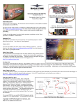
1
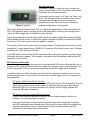
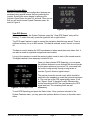
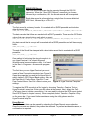
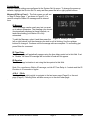
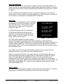
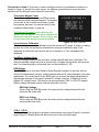
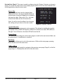
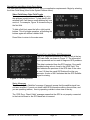
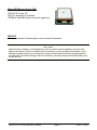
INSPIRE OSD
On-Screen Display with GPS Telemetry
User Manual
Firmware Version 3.2
INTRODUCTION:
INSPIRE is a GPS-based video system designed for
photography applications. Besides offering a remote
shutter interface for digital and film cameras, it also
provides detailed navigational information. The realtime
data is presented as a text overlay on the user’s
existing video camera signal. In addition, the GPS data
for each photo can be stored for later review.
Although INSPIRE is designed for video and still
photography, its applications do not stop there. It can
also be used in applications that serve the mapping
industry, hobby robotics, ham radio, radio control
modeling, and other commercial/hobby uses. In nonGPS applications, it can be used for video telemetry
monitoring of voltages, current, tach-speed, radio
performance, and more.
The main module’s weight is approximately 3 ounces
(85 grams) and the size is 4.0" x 2.4" x 0.4". A
compatible 0.5 ounce (16 gram) micro-sized GPS
receiver allows for a low overall weight.
Figure 1, Inspire Board
Flexible power requirements allow operation on as little as 6VDC at ~185mA. The On-Screen
Display (OSD) video format is NTSC/RS-170. A PAL/CCIR compatible video version is available
upon special request.
FEATURE SUMMARY:
#
#
#
#
#
#
#
#
#
#
#
#
#
Clock/Timer can display local time, UTC time, or elapsed time.
Remote operation of data display and camera shutter.
R/C Glitch counter can capture up to 999 glitch events.
Data recorder can capture GPS information on up to 999 Photos/Events.
Displayed GPS altitude can be MSL or AGL. Accurate ground referenced speed.
Tachometer provides real time display of RPM (up to 65K RPM).
Interval-based station ID (ham call sign or station name).
Real-time GPS based heading degrees, latitude and longitude.
GPS Waypoint bearing & steering indicators (user provided Garmin Geko GPS required).
Buffered GPS output provides NMEA sentences to external devices.
Export GPS records to your custom application via RS-232.
Displays up to 40VDC and current up to +/-50 amps continuous.
Displays radio system voltage.
INSPIRE V3.2 USER MANUAL ©2006
Page 1
May-17-2006
VIDEO BOARD SPECIFICATIONS
!
Dimensions: 4.0" L x 2.4" W x 0.4" H.
!
Weight (less micro GPS receiver): 3 oz.
!
Voltage requirements: 6VDC to 14VDC
!
Current: 80mA typical, 95mA max. 185mA nominal with micro GPS.
!
External Serial I/O port: RS-232/RS-232C, 2400-19.2K baud.
!
Video: Industry standard composite, 1.0V pk-pk, 75 ohms resistive termination.
!
Radio Control Inputs: Industry standard 1mS to 2mS, ~50Hz pulse.
!
Shutter Servo Output: 1mS to 2mS, ~50Hz pulse.
!
Direct Connect Output: Dry contact, opto-isolated, 15VDC @ 10mA max.
!
Battery voltage monitor: 5.7VDC to 17.0VDC, 100mV resolution.
!
RSSI voltage monitor: 0.00VDC to 5.00VDC, 10mV resolution.
!
R/C Battery voltage monitor: 0.00V to 10.00VDC, 10mV resolution.
!
Aux/Motor voltage monitor: 0.0VDC to 40.0VDC, 100mV resolution.
!
Aux/Motor current monitor: 0 to 50A DC continuous, 75A peak, 0.25A resolution.
!
Current sensor: 130 micro-ohms path resistance, DC isolated.
MICRO GPS RECEIVER SPECIFICATIONS
!
Dimensions: 1.2" x 1.2" x 0.4" (30mm x 30mm x 10mm).
!
Module weight: 0.5 oz.
!
Power requirements 5.0V DC @ 75mA (provided by main board).
!
Chipset: SiRF Star III.
!
1Hz update rate.
!
Channels: 20
!
Sensitivity: -159dBm.
!
Accuracy: 10meters 2D, 5 meters 2D WAAS.
!
Cold Start Time: 42 seconds typical.
!
NMEA sentences: GGA, GPGLL, GPGSA, GPGSV, GPRMC, and GPVTG.
!
Serial Interface: 4800 baud, 3.3V TTL non-inverted (provided by main board).
NOTICE
Using the Inspire video system requires safety-minded operation. Under no circumstances should the
telemetry data be used as the primary navigation resource. Never remotely operate the equipment
unless you have direct visual contact at all times and it is safe to do so. Use of the system is entirely
at your own risk.
Digital Products Company, or their distributors, have no control over the installation and use of the
Inspire video system. As such, no liability may be assumed, nor will any liability be accepted, for any
damages resulting from the use of this product. Under no circumstances will the buyer be entitled to
consequential or incidental damages. By act of installing it, the buyer accepts all resulting liability.
INSPIRE V3.2 USER MANUAL ©2006
Page 2
May-17-2006
OSD (ON-SCREEN DISPLAY)
What is shown on INSPIRE’s display is up to you. Every field
group of the OSD is programmable. That is, each field can
be turned on or off, and some allow you to change the data
format. Essentially, you can create a custom formatted
screen that best serves your application or personal tastes.
A view of the default main screen can be seen in Figure 2.
Note: Normally the OSD data is superimposed over your
camera system’s video. However, the screen shot example
presented here has omitted the camera’s view.
Figure 2, Main Screen View
TIME:
At the upper left corner, on the top line, is the elapsed time (shown as 00:01:47). It can also
show the Local or UTC time. The elapsed time is indicated by the clock icon, whereas the
Local/UTC time will omit the symbol. Note: Local/UTC time will not be valid unless a GPS
satellite lock is obtained.
GLITCH COUNT:
Just below the time data is the R/C Glitch counter (shown as G:0). It is active if a radio control
receiver is connected to the system. The glitch value will increment each time a group of
corrupted servo pulses are encountered.
SNAPSHOT/EVENT RECORD COUNT:
Next to the Glitch count is the snapshot/event record counter (shown as R:2). This counter will
advance each time a snapshot is taken using the user supplied R/C system. It can also be used
as a general event counter managed by a user programmable timer. In either case, the GPS
navigation data is stored with each new count.
WAYPOINT ROUTE NAVIGATION:
Note: The waypoint route navigation fields are only active when a Garmin Geko 201 GPS
receiver is installed. They are NOT active if the micro GPS receiver module is installed.
Below the Glitch and Snapshot counter data are the GPS waypoint navigation fields. The first
number (shown here as 039) is the turn/steer bearing. Next to it is the steerage indicator, which
in this example is shown as a right turn. The third field, shown as 0.03, is the waypoint
destination in miles (can be displayed as kilometers too). The final number (shown as 08) is the
destination’s waypoint number, as provided by your GPS receiver’s routing schedule. The
example shown here indicates that waypoint destination #8 is 0.03 miles away and requires a
39 degree right turn for the correct bearing.
ALTITUDE AND SPEED:
At the upper right corner are the altitude and speed (shown as 170ft/20mph). This data is
available when the GPS option is used. Below it is the motor tachometer data (shown as 630
rpm).
STATION ID:
The text field below the Altitude shows the station ID message (shown here as “Inspire OSD”). It
appears at user specified intervals. This message can be easily edited and allows up to eleven
characters.
INSPIRE V3.2 USER MANUAL ©2006
Page 3
May-17-2006
GPS HEADING, LONGITUDE, AND LATTITUDE:
The first text line, at the lower left, is the course heading. It is referenced to TRUE north, not
magnetic north. Below that is the longitude and latitude navigation data. These fields are active
when the GPS receiver has established a satellite lock.
GPS ERROR INDICATOR:
If the GPS signal is lost, or the data is invalid, then there
will be a question mark shown at the longitude field, as
shown in Figure 4. When this occurs, the GPS
information is not valid and should NOT be used.
RELATIVE SIGNAL STRENGTH INDICATOR:
At the lower right (shown as 0.71V) is the relative signal
strength indicator (RSSI) voltage. It can also be
configured to show a moving bar graph instead. This field
can be used in applications ranging from general low
voltage monitoring to reporting signal levels from a
communications receiver.
Figure 3, Main Screen View
R/C System Signal Indicator:
To the right of the RSSI field is an antenna icon. This graphic will blink for alerting purposes
whenever R/C signal problems are occurring.
Aux/Motor Voltage and Current:
Directly below the RSSI information is the auxiliary/motor voltage and current fields (shown as
4.9V -0.6A). This is valuable data for electric motor operation. The voltage can be configured
with an alarm threshold for additional visual warning.
The last data line shows the R/C system’s voltage (shown as 5.21V)) and the OSD board’s
operating voltage (shown as 8.6V).
Note: The OSD board’s operating voltage must not be allowed to go below 5.6VDC under any
circumstance. If it does, the OSD voltage field will say ?ALERT.” Operation at this low voltage
will adversely affect displayed data accuracy and video quality.
INSPIRE V3.2 USER MANUAL ©2006
Page 4
May-17-2006
FIVE-WAY JOYSTICK
A miniature ?finger tip” joystick is used to control the
various system features. The short ribbon cable allows
mounting it at a convenient location.
Figure 4, Joystick
The joystick has five inputs: Left, Right, Up, Down, and
Enter. The up/down buttons are used to move around
the menus and left/right are used to change the
selected menu item. The Enter button is chosen by
pressing straight down on the joystick.
The joystick board includes a status LED. If no alerts are present then it will be on steadily (all
OK). If the camera’s video is missing or bad, it will slowly blink. If there is a low voltage issue
(motor or OSD voltage alert) it will blink at a very fast rate.
During normal operation the left/right joystick buttons are used to toggle the timer/clock display.
When elapsed time is chosen, a small clock graphic is shown to the left of the data field. When
the local or UTC time is in view, the clock graphic is omitted.
The joystick is also used to reset some common parameters. Pressing the Enter button for one
second will (1) reset elapsed time to 00:00:00, (2) reset the AGL altitude to zero, and (3) display
the station ID. It also resets the ID timer.
If the OSD video is turned off by the R/C transmitter then pressing the up/down joystick buttons
will cause the video to appear. This is handy if you need to see the telemetry data and the R/C
transmitter is not close by.
R/C CONTROLLED FEATURES
INSPIRE has two servo cables that connect to a user provided R/C receiver. Besides their use to
monitor for R/C signal glitches and receiver voltage, they are also used to control features from
the R/C transmitter. You can use spare channels that are stick or toggle switch activated.
In addition, there is an R/C controlled output that can be configured to activate a servo or low
current switched circuit. This is ideal for use as camera shutter trigger, but it is not restricted to
that application.
R/C INPUTS: OSD VIDEO ON/OFF CONTROL
The R/C-VID cable can be used to turn the OSD on/off from the R/C transmitter. This is a
handy way to obtain a clear camera image for data-free video recording and viewing.
While the OSD is off, any alarm condition (low voltage, lost R/C signal, glitches) will
cause the OSD data to reappear.
R/C INPUTS: AUXILIARY CAMERA/EVENT CONTROL
The R/C-AUX cable can be used to remotely control a digital camera’s shutter, an
accessory, or to record events to memory.
Each remote activation increases the record count value that is displayed. In addition,
the GPS’s navigation data is saved (up to 999 records) for later review. By matching the
camera’s stored photo count (or time stamp) to INSPIRE’s stored records, the GPS
information to each photo can be determined.
INSPIRE V3.2 USER MANUAL ©2006
Page 5
May-17-2006
Of course a camera does not need to be used with this feature. Perhaps your application
will want to use the R/C transmitter only to store useful GPS data upon remote
command. Lastly, a user-configured Event timer can be setup to periodically record the
GPS data for you.
R/C OUTPUT: SHUTTER CONTROL SERVO
The camera/event control input operates the Shutter Control output. This output can
control a standard R/C servo and is available when the system’s CAMERA MODE is set to
“Servo” (please see CAMERA MODE, page 10).
This output is typically used to snap photos. If your digital (or film) camera is already
equipped with a R/C servo compatible interface, then it is merely plugged into the 3-pin
female servo connector. A very simple shutter activation method can be achieved by
mounting a servo on the camera (3M double sided tape is often used).
The servo output is digitally filtered and protects the servo from R/C signal glitches. It
also has a hold-last-position feature in the event the R/C signal is lost.
SWITCHED OUTPUT: DIRECT CONNECT CONTROL
In addition to the servo interface, there is a 2-pin header connector for direct connect
switched applications. This output is available when the system’s CAMERA MODE is set to
“Direct” (please see CAMERA MODE, page 10).
The output is a 2-wire interface (labeled Out+/Out-) that can be wired across the electric
shutter switch of digital and film cameras. This helps to eliminate the mechanical setup of
the servo method. Please do not ask for specific camera connection advice -- we are not
equipped to help in that area.
INSPIRE V3.2 USER MANUAL ©2006
Page 6
May-17-2006
SYSTEM FEATURES MENU
INSPIRE’s record storage and configuration features are
accessed using special menus that are guided by the
joystick. Entering the menu begins by pressing the
joystick’s Enter button for three (3) seconds. Once you do
that you will see the main System Features menu, as
seen in Figure 5.
Figure 5, System Features
VIEW GPS REPORT
When you first enter the System Features menu the ?View GPS Report” entry will be
blinking. To select this entry, press the joystick’s left or right buttons.
The GPS report feature is used to access the navigation data that was saved. There is
sufficient memory for up to 999 records. This data is retained, even if INSPIRE is turned
off.
The data is used to display the GPS coordinates of where each photo was taken. But, it
can also be used as a general navigational event marker.
It is up to the operator to match the camera’s photo count to each of the stored records.
The digital camera’s time stamping is useful for this.
Once you have chosen GPS Reporting, you can press
the up/down buttons to move through the stored records.
A short press advances one record. Or, press and hold
the button to skip quickly through a long series of
records. Figure 6 shows a typical record.
Figure 6, GPS Report View
The top line shows the record count, which should be
matched to the snapshot or event that you are interested
in. The next line is the GPS signal quality status. If will
say ?Signal: Good” if the data is valid. Otherwise the
current record should NOT be used because the GPS
signal was bad. The remaining fields are self
explanatory.
To exit GPS Reporting just press the Enter button. Once you have returned to the
System Features menu, you may press the up/down buttons to move to the other menu
items.
INSPIRE V3.2 USER MANUAL ©2006
Page 7
May-17-2006
SEND GPS REPORT
The GPS record data can also be exported through the RS-232
connector. When the “Send GPS Reports” menu entry is chosen,
followed by a confirmation, ALL the stored records will be exported.
Each data record is reformatted as a single line of comma delimited
ASCII text, followed by a <CR><LF>.
Figure 7, RS-232
The first record is a dummy header. It is marked with a $HDR preamble and includes
data dictionary titles:
$HDR,REC,SIG*,HH:MM:SS,LONGITUDE**,LATITUDE**,ALTITUDE****,SPEED*,DEG**<CR><LF>
The data records that follow are marked with a $DAT preamble. These are the GPS data
values that were stored during each photo or event:
$DAT,001,Good,18:43:33,-121.140608,+38.686096,00000ft AGL,000mph,029.0<CR><LF>
Any data record that is corrupt will be marked with a $ERR preamble and will have empty
fields:
$ERR,002,!ERR,,,,,,<CR><LF>
The end of the file will be stamped with a short data record that is marked with a $EOF
preamble:
$EOF,000,%EOF,,,,,,<CR><LF>
One method of retrieving the stored records is to
use HyperTerminal. It is a basic Microsoft
Windows serial communications utility. It is found
in the Start-> Programs-> Accessories program
tab.
The first time you use HyperTerminal you must
create a New Connection template (see Figure 8).
Open the properties box and set the baud rate to
match Inspire’s GPS Report Baud setting. Also set
the Data bits=8, Parity=None, Stop Bit=1, and
Flow Control=None. Use File->Save to save your Figure 8, HyperTerminal Template
settings.
To capture the GPS records to a file, begin by choosing Transfer->Capture Text on
HyperTerminal’s menu bar. Enter your file name at the prompt. Next, select the Call>Call menu item to initiate a connection. It is now ready to receive the GPS report (select
Send GPS Report in Inspire’s menu). When complete, select Transfer->Capture->Stop
on the menu bar. If you need further assistance using the utility please see the
HyperTerminal help file.
ERASE REPORT
The GPS record data can be erased by selecting the Erase Reports menu selection.
Once the records are deleted, they cannot be restored. To prevent accidental erasure, a
confirmation is required.
INSPIRE V3.2 USER MANUAL ©2006
Page 8
May-17-2006
SYSTEM SET UP
INSPIRE’s default settings are configured in the System Set Up menu. To change the power-up
defaults, highlight the SYSTEM SET UP entry and then press the left or right joystick buttons.
MESSAGE ID SETUP PAGE 1: The first screen you will see
is ?Msg ID Setup Page 1,” as shown in Figure 9. It is
used to setup the Station ID message and its interval
time.
ID Message
The ID message can be nearly any text you want,
up to eleven characters. The message you choose
is automatically displayed at timed intervals, so
tasks like showing your Station ID is fully
automated.
Figure 9, Message ID Setup
To edit the Message, select it and then press the
left or right buttons until the character you wish to edit is blinking. Use the up/down
buttons to change it. Continue until the message edits are complete. To end editing just
press Enter for a moment.
ID Time Delay
The ID message will periodically appear using the time delay period set in this field. If set
to ?Disable” the timed ID message will be turned off and will not appear.
ID Duration
The ID message’s duration is set using the time period in this field.
Note: For a continuous Station ID message, set the ID Time Delay to 1-minute and the ID
Duration to 61-seconds or higher.
<PG-6 PG-2>
Use the left and right joystick to navigate to the last menu page (Page-6) or the next
page (Page-2). Pressing Enter will also move you to the next menu page.
.
INSPIRE V3.2 USER MANUAL ©2006
Page 9
May-17-2006
CAMERA/EVENT PAGE 2: Once you are satisfied with page 1, you can move to the next page by
pressing the joystick’s Enter button. This leads to the ?Camera/Event Page 2” configuration
menu, as seen in Figure 10.
Camera Mode
The R/C-Aux channel input can be configured to
operate a standard R/C Servo or it can provide a
switched output for direct (hardwired) camera
connection.
The SERVO setting is used for R/C servo activated
shutter installations. When this entry is chosen
your shutter servo can be installed on the R/C
cable labeled “Shut”.
The DIRECT setting configures the “dry closure”
Figure 10, Camera/Event Setup
output (Out+/Out-) for use as a switched On/Off
output. It is also used for timed event applications.
Note: The special optically isolated output requires connecting a 2-wire cable to Out+ and
Out-. The 3-wire female servo cable cannot be used during the DIRECT mode.
Wake/Event Time
This parameter is used to keep the digital camera awake. It is also used for timer-based
event recording. The time period sets the delay before the servo is moved or the direct
connect output is activated, with a fixed duration of two seconds. The timer is also used
for event recording, which is useful for periodic storage of GPS data.
Note: The Wake/Event timer will reset whenever the Aux-R/C channel is activated. This
is convenient when controlling a digital camera since it eliminates unnecessary dummy
snapshots that might be needed to keep the camera awake.
Wake/Event Record
This parameter is as follows:
On: Use this mode if you need to automatically store GPS data at each camera
Wake-up or at timed events.
Off: Use this mode if you do not want to store GPS data during camera Wake-up
or timed events.
Servo Direction
The Servo Direction parameter controls the Aux channel’s R/C servo pulse thresholds for
the Camera Shutter and Event trigger On and Off states.
Normal:
1.65mS or Higher is On state
1.57mS or Lower is Off state
Reverse:
1.35mS or Lower is On state
1.43mS or Higher is Off state
INSPIRE V3.2 USER MANUAL ©2006
Page 10
May-17-2006
Servo Pulse Position
When the Camera Mode is set for Servo operation, the Servo Pulse field appears. It is
used to set the servo arm position that is needed during the camera Wake-up. The value
shown is the pulse period of the R/C signal that will be used and can range from 1.05mS
to 1.95mS.
As you change the pulse parameter, the servo arm will accurately move to reflect the
chosen value. You can use this to carefully align the servo. When the menu is exited, the
servo will return to the position commanded by R/C transmitter.
Servo Test
The R/C Servo Test feature is useful for checking
the operation of the two R/C channels. The data
seen here will show you the exact servo pulse
values that are sent by your R/C transmitter.
Please see Figure 11.
For PPM R/C systems, the R/C transmitter’s
ATV/EPA and Dual Rate mixes should be
adjusted so that the extreme pulse values fall
within a range of 1.0mS to 2.0mS. Do not go
below 1.0mS or above 2.0mS.
Figure 11, Servo Test
For PCM or DSP based R/C systems, please
ensure that the pulse values observe the same restrictions as discussed above.
However, the PCM’s failsafe should be set so that the failsafe signal cause the servo test
screen to display ?Bad Pulse.” This will occur with pulses that are less than 0.85mS or
greater than 2.15mS. Forcing such exaggerated pulse values will allow the glitch counter
to count failsafe events.
Note: When using a R/C receiver with failsafe, the R/C-Vid servo channel must be
programmed to turn on the OSD video upon failsafe detection.
While you review the R/C Servo Test screen, take note of the two State fields as you
move the transmitter’s sticks or toggle switches. These fields will indicate the control
state of the Video On/Off and Shutter/Aux channels. Use the transmitter’s servo
reversing and ATV/EPA mixing features to provide correct response to the displayed
messages. In other words, when you want the OSD’s main screen video to be shown, the
Video State should display ?On.” When you want enable the camera shutter, the Aux
State should display ?On.”
<PG-1 PG-3>
Use the left and right joystick to navigate to the previous menu page (Page-1) or the next
page (Page-3). Pressing Enter will also move you to the next menu page.
INSPIRE V3.2 USER MANUAL ©2006
Page 11
May-17-2006
GPS FORMAT PAGE 3: This menu is used to configure the
GPS related parameters. Please see Figure 12.
As with the other menus, the up/ down joystick buttons
move the menu selection and the left/right buttons alter
the menu entry.
Coordinate Format
The GPS coordinates can be displayed in Decimal
or NMEA format. Most applications will use the
Decimal setting.
Figure 12, Setup GPS
Measurement Units
The GPS’s speed and altitude units can be configured for the preferred region. You may
choose USA (miles per hour and feet) or Euro (kilometers per hour and meters).
Hours Offset
Your local time may differ from the GPS’s default time zone. If you wish to set the clock
to your local time zone, then enter your time zone’s offset here. If you wish to use UTC
time, then select zero.
Altitude Units
The Altitude can be either AGL (Above Ground Level) or MSL (Mean Sea Level). When
using the AGL mode the altitude should be zeroed before each flight. During normal use,
this is performed by pressing the Joystick’s ENTER button for two seconds.
Report Baud
This entry is used to select the RS-232 serial baud rate for exporting the GPS reports.
When using the data export feature, be sure to set your host to match the baud rate
parameter that is used here.
<PG-2 PG-4>
Use the left and right joystick to navigate to the previous menu page (Page-2) or the next
page (Page-4). Pressing Enter will also move you to the next menu page.
INSPIRE V3.2 USER MANUAL ©2006
Page 12
May-17-2006
GPS HARDWARE PAGE 4: This menu is used to configure
the GPS hardware related parameters, as shown in
Figure 13. As with the other menus, the up/down joystick
buttons move the menu selection and the left/right
buttons alter the menu entry.
GPS Module ID
This entry is used to select the GPS Module type
that is used. If the micro-sized GPS module is
installed then the “EM-406" entry must be selected.
Select “Generic” if the Garmin Geko 201 is used.
Figure 13, Setup GPS Hardware
GPS Baud Rate
This entry is used to display the GPS Module’s baud rate. When the ID is set to “Generic”
the baud rate can set to match your GPS receiver’s requirements.
WAAS/SBAS Satellite Mode
This entry is shown when the GPS Module Type is “EM-406." It selects the EM-406's
WAAS satellite correction feature. If the WAAS signal is found in your geographical area
(depends on satellite position and USA location) then the displayed GPS data may be
more accurate. This entry can be turned On/Off; no foul will occur if it is turned On in an
area that doesn’t support the WAAS feature.
Motion Filter
This entry is shown when the GPS Module Type is “EM-406." Some of the EM-406 data
will not be stable or meaningful when the GPS module is stationary. If this is a nuisance
in your application, you can turn on the Motion Filter to help stabilize the data whenever
motion stops. The data will not update until the ground speed is greater than 2.7mph
(4.3km/hr), or until approximately 50 feet (15 meters) has been traveled.
<PG-3 PG-5>
Use the left and right joystick to navigate to the previous menu page (Page-3) or the next
page (Page-5). Pressing Enter will also move you to the next menu page.
INSPIRE V3.2 USER MANUAL ©2006
Page 13
May-17-2006
FEATURE SETUP PAGE 5: This menu is used to configure INSPIRE’s miscellaneous features, as
shown in Figure 14. As with the other menus, the up/down joystick buttons move the menu
selection and the left/right buttons alter the menu entry.
Tachometer Magnet Count
The tachometer is based on a Hall Effect sensor
that monitors shaft mounted magnets. The magnet
count value is set to match the number of pulse
interruptions that occur for each revolution of the
monitored wheel, blade, or gear set.
Tach Magnet Alignment: A star character will
appear after the Magnet Count value whenever the
tachometer magnet is sensed. This is a handy way
to help ensure your magnet is correctly aligned.
Figure 14, Misc Features
Current Sensor Calibration
The current sensor must be calibrated for an idle current of 0.0 amps. It is best to unplug
at least one of the current sensor wires before running the calibration step. If the
calibration is performed, and found to be out of tolerance, a ?Fail” message will be
displayed.
Aux/Motor Voltage Alarm
Upon low voltage detection, the aux/motor voltage field will flash as a visual alert. The
minimum allowed voltage set point is chosen here. Voltages that are lower will cause an
alert. If a visual warning is not wanted, then set the threshold to ?Off.”
RSSI Display
The RSSI Display is used as a Relative Signal Strength Indicator for sources such as
fluid level measurement systems, communication receiver RF signal strengths, and other
applications. The usual format for the RSSI field is a six-level bar graph that shows the
approximate strength of the signal’s scaled DC voltage. However, it defaults to a nongraphic DC voltage format. This feature can accommodate 0.00V to 5.00V DC signals.
Higher voltages will need custom external attenuation circuitry.
RSSI High Voltage
When using the RSSI Bar mode, this entry sets the voltage threshold for the
maximum bar scale level.
RSSI Low Voltage
When using the RSSI Bar mode, this entry sets the voltage threshold for the
minimum bar scale level.
<PG-4 PG-6>
Use the left and right joystick to navigate to the previous menu page (Page-4) or the next
page (Page-6). Pressing Enter will also move you to the next menu page.
INSPIRE V3.2 USER MANUAL ©2006
Page 14
May-17-2006
SYSTEM SETUP PAGE 6: This menu is used to configure INSPIRE’s System Features, as shown in
Figure 15. As with the other menus, the up/down joystick buttons move the menu selection and
the left/right buttons alter the menu entry.
Screen Size
The main screen’s size can be changed here.
When set to CROP, the top and bottom fields are
moved inward to prevent clipped text on systems
that crop the video. When set to FULL, the main
screen’s text fields use the full screen size.
Note: You will not see the effects from changing
this setting until you return to the main screen.
Figure 15, System Features
Joystick Direction
The Joystick button assignments can be reversed. This allows for installing the joystick
pad upside down (rotated 180 degrees). When set to Normal, the status LED will be on
the right. If set to Reverse, the status LED will be on the left.
Factory Reset
The factory default settings for all the menu pages, as well as the main screen fields, can
be restored here. A confirmation is required.
Exit Setup
This selection allows you to exit to the main menu. While on this setup page, pressing
Enter will also exit to the main menu.
<PG-5 PG-1>
Use the left and right joystick to navigate to the previous menu page (Page-5) or the first
page (Page-1). Pressing Enter will exit to the main menu.
INSPIRE V3.2 USER MANUAL ©2006
Page 15
May-17-2006
SYSTEM FEATURES MENU: VIDEO FIELD SETUP
The data fields are easily turned on or off, per your application requirements. Begin by selecting
the Video Field Setup (found in the System Feature menu).
Video Field Setup: Data Field Toggle
You can move around the various fields by using
the up/down joystick buttons. To help identify the
selected field, it will have a small skeleton key icon
next to it. For example, Figure 16 shows the key at
the first field.
To hide a field just press the left or right joystick
buttons. This is a toggle operation, so pressing the
buttons again will restore a hidden field.
Press Enter to return to the main menu.
Figure 16, Video Field Setup
SYSTEM FEATURES MENU: GPS DIAGNOSTICS
The GPS Diagnostics selection is used to look at the key
GPS data fields, as shown in Figure 17. The information
that is presented can be used to diagnose GPS problems.
The data is extracted from the GPS receiver. One useful
troubleshooting value is found in the HDOP field. This
field indicates the precision of the GPS data. If the value
is over 2.0 then the overall GPS data will not be very
accurate. A value of 99.0 indicates that the GPS Satellite
signal is missing.
Figure 17, GPS Diagnostics
Status Messages
The “Searching For Satellites” message (if present) means that the satellite signal has
not been acquired. If you do not obtain valid GPS information within a few minutes, and
you are operating indoors, then try operating outside in clear view of the sky.
The “GPS Error: Check Cable" message means that the GPS is not properly connected
to the INSPIRE Board or the GPS baud rate is incorrect.
INSPIRE V3.2 USER MANUAL ©2006
Page 16
May-17-2006
MICRO-GPS MODULE STATUS LED
LED Off: DC Power Off.
LED On: Searching for satellites.
LED Blink: Satellites found, successful signal lock.
SERVICE
For service, please visit www.dpcav.com for contact information.
DISCLAIMER
Digital Products Company, or their distributors, have no control over the installation and use of the
Inspire video system. As such, no liability may be assumed, nor will any liability be accepted, for any
damages resulting from the use of this product. Under no circumstances will the buyer be entitled to
consequential or incidental damages. By act of installing it, the buyer accepts all resulting liability. Use
at your own risk.
INSPIRE V3.2 USER MANUAL ©2006
Page 17
May-17-2006