1
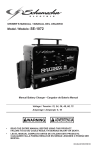
OWNER’S MANUAL • Manual del usuario
Power Inverter / Convertidor de Energía
Models / Modelos: PI-1000 & PI-1500
Converts 12V DC Battery Power to 120V AC Household Power
Convierte la Energía de Baterías de 12V de CD a 120V de
CA de Energía Doméstica
ADVERTENCIA
•
•
READ THE ENTIRE MANUAL BEFORE USING THIS PRODUCT.
FAILURE TO DO SO COULD RESULT IN SERIOUS INJURY OR DEATH.
LEA EL MANUAL COMPLETO ANTES DE UTILIZAR ESTE PRODUCTO.
CUALQUIER FALLA PODRÍA RESULTAR EN SERIAS LESIONES O PODRÍA
SER MORTAL.
00-99-001142/00
DO NOT RETURN THIS PRODUCT
TO THE STORE!
Call Customer Service for Assistance:
800-621-5485
¡NO LO DEVUELVA este producto
A LA TIENDA!
Llame a Servicios al Cliente para Asistencia:
800-621-5485
Table of Contents
Section
Page
IMPORTANT SAFETY INSTRUCTIONS
1
INVERTER FEATURES
2
BEFORE USING YOUR POWER INVERTER
3
FASTENING THE INVERTER TO A FLAT SURFACE
3
CONNECTING INVERTER CABLES
3
USING THE GFCI OUTLET (MODEL PI-1500 ONLY)
5
OPERATING INSTRUCTIONS
5
POWER SOURCE
6
LED INDICATOR AND SHUTDOWN PROTECTION
6
IF THE INVERTER FUSE BLOWS
6
MAINTENANCE INSTRUCTIONS
7
Troubleshooting
7
BEFORE RETURNING FOR REPAIRS
7
SPECIFICATIONS
7
Limited warranty
8
ÍNDICE
SECCIÓN
PÀGINA
INSTRUCCIONES IMPORTANTES DE SEGURIDAD
12
CARACTERÍSTICAS DEL CONVERTIDOR
13
ANTES DE USAR SU CONVERTIDOR DE ENERGÍA
14
PARA SUJETAR EL CONVERTIDOR A UNA SUPERFICIE PLANA
15
PARA CONECTAR LOS CABLES DEL CONVERTIDOR
15
PARA USAR LA TOMA DE CORRIENTE GFCI
(SOLAMENTE MODELO PI-1500)
16
INSTRUCCIONES DE OPERACIÓN
17
FUENTE DE ENERGÍA
18
INDICADOR LED Y PROTECCIÓN DE DE APAGADO
18
SI SE QUEMA EL FUSIBLE DEL CONVERTIDOR
18
RESOLUCIÓN DE PROBLEMAS
19
ESPECIFICACIONES
19
IMPORTANT: READ AND SAVE THIS SAFETY AND INSTRUCTION MANUAL.
SAVE THESE INSTRUCTIONS – The PI-1000 and PI-1500 offer a wide range of features
to accommodate your needs. This manual will show you how to use your inverter safely and
effectively. Please read, understand and follow these instructions and precautions carefully,
as this manual contains important safety and operating instructions. The safety messages
used throughout this manual contain a signal word, a message and an icon.
The signal word indicates the level of the hazard in a situation.
Indicates an imminently hazardous situation which, if not avoided, will result in
death or serious injury to the operator or bystanders.
Indicates a potentially hazardous situation which, if not avoided, could result in
death or serious injury to the operator or bystanders.
Indicates a potentially hazardous situation which, if not avoided, could result in
moderate or minor injury to the operator or bystanders.
Indicates a potentially hazardous situation which, if not avoided, could result in
damage to the equipment or vehicle or property damage.
Safety messages in this manual contain two different type styles.
• Unnumbered type states the hazard.
• Numbered type states how to avoid the hazard.
The icon gives a graphical description of the potential hazard.
Pursuant to California Proposition 65, this product contains chemicals known to
the State of California to cause cancer and birth defects or other reproductive
harm.
1.
IMPORTANT SAFETY INSTRUCTIONS
SAVE THESE INSTRUCTIONS
RISK OF ELECTRIC SHOCK OR FIRE.
1.1 Keep out of reach of children.
1.2 Keep the inverter well ventilated in order to properly disperse heat generated while it is in
use. Make sure there are several inches of clearance around the top and sides, and do
not block the slots of the inverter.
1.3 Make sure the inverter is not close to any potential source of flammable fumes, gases or
clothing.
1.4 Do not place the inverter in areas such as battery compartments or engine compartments
where fumes or gases may accumulate.
1.5 Keep the inverter dry.
1.6 DO NOT allow the inverter to come into contact with rain or moisture.
1.7 DO NOT operate the inverter if you, the inverter, the device being operated or any other
surfaces that may come into contact with any power source are wet. Water and many
other liquids can conduct electricity, which may lead to serious injury or death.
1.8 Do not place the inverter on or near heating vents, radiators or other sources of heat or
flammable materials.
1.9 Do not place the inverter in direct sunlight. The ideal air temperature for operation is
between 50° and 80°F (10º and 27ºC).
•1•
1.10 Only connect the power inverter to a 12 volt battery or power supply. Do not attempt
to connect the inverter to any other power source, including an AC power source.
Connecting to a 6 volt or 16 volt battery will cause damage to the inverter.
1.11 Make sure the AC plug is tight.
1.12 Do not modify the inverter in any way including cables, plugs, switches or AC receptacles
as it may result in property damage or personal injury.
1.13 Incorrect operation of the inverter may result in property damage or personal injury.
The inverter output is 120V AC and can shock or electrocute the same as
any ordinary household AC wall outlet.
1.14 To reduce the risk of electric shock, disconnect the inverter from the power source before
attempting any maintenance or cleaning. Simply turning off the controls will not reduce
this risk.
1.15 Do not operate the inverter with damaged cables; have the cables replaced immediately
by a qualified service person. (Call customer service at: 1-800-621-5485.)
1.16 Do not operate the inverter if it has received a sharp blow, been dropped or otherwise
damaged in any way; take it to a qualified service person. (Call customer service at:
1-800-621-5485.)
1.17 Do not disassemble the inverter; take it to a qualified service person when service or
repair is required. Incorrect reassembly may result in a risk of fire or electric shock. (Call
customer service at: 1-800-621-5485.)
1.18 Working in the vicinity of a lead-acid battery is dangerous. Batteries generate explosive
gases during normal battery operation. For this reason, it is of utmost importance that you
follow the instructions each time you use the inverter.
1.19 This inverter employs parts, such as switches and circuit breakers, that tend to produce
arcs and sparks. If used in a garage, locate this inverter 18 inches (46 cm) or more above
the floor level.
1.20 Do not use the inverter with a product that draws a higher wattage than the inverter can
provide, as this may cause damage to the inverter and product.
2.
INVERTER FEATURES
1. ON/OFF Rocker Switch – Turns the inverter ON and OFF.
2. LED Indicator Light – (Green = power ON, Red = Overload/Interruption in power.)
3. 12-Volt Power Cord – One pair.
4. 120V AC Outlet – Two Standard (Model PI-1000) Two GFCI (Model PI-1500).
5. High-Speed Cooling Fan(s) – Keeps the inverter cool. The speed of the fan is faster
as the load increases. The fan does not run when the inverter is turned OFF.
6. Analog Output Power Display – Shows 120V AC continuous power consumed. Five
lights indicate half of the continuous output power and 10 lights indicate full continuous
power consumption. When the inverter is OFF, the lights do not illuminate.
7. Positive Battery Cable Terminal (Red) – Accepts Positive connector cable.
8. Negative Battery Cable Terminal (Black) – Accepts Negative connector cable.
9. Ground Terminal – Grounds inverter to reduce electrical shock.
10.Thermal Protection – When the inverter case becomes hot (exceeds 145° F), the
inverter shuts down until it cools off an then automatically restarts.
11. Surge Protection – When the power input from the vehicle’s battery exceeds 15 volts,
the inverter shuts down. Once the voltage drops down to less than 14, it automatically
restarts.
12.Low-Battery Protection – When the power input from the vehicle’s battery drops to
approximately 10 volts, the inverter shuts down.
•2•
3.
BEFORE USING YOUR POWER INVERTER
NOTE: Do not use the inverter with a product that draws a higher wattage than the inverter
can provide, as this may cause damage to the inverter and product.
When you turn on a device or a tool that runs on a motor, the device goes through two stages:
1. Start Up – Requiring an initial surge of power (commonly known as the “starting or peak
load”).
2. Continuous Operation – Power consumption drops (commonly known as the
“continuous load”).
The wattage (WATTS) or amperes (AMPS) can normally be found stamped or printed on most
devices and equipment, or in the user’s manual. Otherwise, contact the manufacturer to find
out whether the device you want to use is compatible with a modified sine wave.
To calculate the wattage: Wattage = AMPS x 120 (AC Voltage).
To calculate the starting load: Starting Load = 2 x WATTS. In general, the start up load of the
device or power tool determines whether or not your inverter has the capability to power it.
To calculate the continuous load: Continuous Load = AMPS x 120 (AC Voltage).
Always run a test to establish whether or not the inverter will operate a
particular piece of equipment or device. In the event of a power overload, the inverter is
designed to automatically shut down. This safety feature prevents damaging the inverter while
testing devices and equipment within the wattage range of the inverter.
If a device does not operate properly when first connected to the inverter, turn the inverter On/
Off switch ON, OFF, and ON again in quick succession. If this procedure is not successful,
it is likely that the inverter does not have the required capacity to operate the device in
question.
This inverter uses a nonsinusoidal waveform. Therefore we do not
recommend you use it to power the following devices:
1. Switch Mode Power Supplies;
2. Linear Power Supplies;
3. Class 2 Transformers;
4. Line Filter Capacitors;
5. Shaded Pole Motors;
6. Fan Motors;
7. Microwave Ovens;
8. Fluorescent and High Intensity Lamps (with a Ballast); and
9. Transformerless Battery Chargers.
Doing so, may cause the device to run warmer or overheat.
4.
FASTENING THE INVERTER TO A FLAT SURFACE
For your convenience, the inverter can be fastened to a flat surface, horizontally or vertically.
The area where the inverter is to be fastened must be dry, well ventilated and away from any
combustible material or fumes.
1. Turn off and disconnect the inverter.
2. Place the back of the inverter with the mounting bracket against a flat, secure surface.
3. Attach the inverter to the flat surface using corrosion resistant screws.
5.
CONNECTING INVERTER CABLES
The inverter and power source must be in the OFF mode.
Make sure to connect the inverter to a 12 volt power supply only.
To avoid electrical shock, it is necessary to ground the inverter as well as the device powering
it. The inverter should be grounded using a #8 AWG copper wire (not included).
•3•
NOTE: Do not turn on the inverter or the power source until the inverter and the power source
are grounded.
To ground the inverter:
1. Turn off and disconnect the inverter.
2. Locate the chassis ground screw below the negative terminal on the left side of the
inverter.
3. Remove the outer hex nut and loosen the second hex nut.
4. Strip the insulation of the #8 AWG copper wire back 1.5” and wrap the bare end of the
wire around the ground screw between the two washers.
5. While holding the wire in place, tighten the hex nut securely. Then, replace the other
hex nut and tighten it securely.
6. Attach the other end of the wire to a properly grounded location:
VEHICLE: Connect to the chassis, unpainted frame part, or engine block of the vehicle.
BOAT: Connect to the boat grounding system.
FIXED LOCATION: Connect to a ground rod or other appropriately rated ground.
Inverter Connection:
1. Locate the Positive and Negative plastic terminals located on the left side of the inverter.
Using a standard (flathead) screwdriver, unscrew the positive (red) and negative (black)
terminal screws just enough to be able to insert the bare end of the connector cables.
2. Insert the bare end of the positive (red) cable into the positive (red) terminal. Insert the
bare end of the negative (black) cable into the negative (black) terminal. Tighten each
terminal screw so that the cable cannot come loose.
Connecting Inverter Cable to 12V Battery or 12V Power Source:
RISK OF CONTACT WITH BATTERY ACID. BATTERY ACID IS
A HIGHLY CORROSIVE SULFURIC ACID.
A SPARK NEAR THE BATTERY MAY CAUSE A BATTERY EXPLOSION. TO
REDUCE THE RISK OF A SPARK NEAR THE BATTERY:
1. Keep hands, hair, clothing and jewelry clear of battery terminals.
2. Wear eye protection and clothing protection.
3. For a negative-grounded vehicle, connect the POSITIVE (RED) terminal from the
inverter to the POSITIVE (POS, P, +) ungrounded post of the battery. Connect the
NEGATIVE (BLACK) terminal to the vehicle chassis or engine block away from the
battery. Do not connect the terminal to the carburetor, fuel lines or sheet-metal body
parts. Connect to a heavy gauge metal part of the frame or engine block.
4. For a positive-grounded vehicle, connect the NEGATIVE (BLACK) terminal from the
inverter to the NEGATIVE (NEG, N, -) ungrounded post of the battery. Connect the
POSITIVE (RED) terminal to the vehicle chassis or engine block away from the battery.
Do not connect the terminal to the carburetor, fuel lines or sheet-metal body parts.
Connect to a heavy gauge metal part of the frame or engine block.
5. To disconnect the inverter, reverse the above steps.
NOTE: The internal speaker may make a brief “beep” when the inverter is being connected to
or disconnected from the 12 volt power source.
Failure to make the correct connections will result in blown fuses and
permanent damage to the inverter.
•4•
6.
USING THE GFCI OUTLET (MODEL PI-1500 ONLY)
The PI-1500 inverter includes two GFCI (Ground Fault Circuit Interrupter) outlets located
on the right side of the inverter. The purpose of a GFCI outlet is to quickly stop the flow of
electricity in the event a ground fault occurs on the device plugged into the inverter’s GFCI
outlet. Use only a 3-prong grounded plug when using the GFCI outlets.
The GFCI outlets provide auxiliary power to 120V AC devices that require less than 15 amps;
and auxiliary power to 120V AC devices that require less than 15 amp. If using both GFCI
outlets at the same time, the amperage cannot exceed a total of 15 amps for both devices
combined.
The GFCI must be tested before each use. To test:
1. Connect the inverter (see CONNECTING INVERTER CABLES section).
2. Turn the inverter on.
3. Push the “Reset” button located on the GFCI receptacle first to assure normal GFCI
operation.
4. Plug a night light (with an ON/OFF switch) or other device (such as a lamp) into the
GFCI receptacle, and turn the device ON.
5. Push the “Test” button located on the GFCI receptacle. The night light (or other device)
should turn OFF.
6. Push the “Reset” button and the light (or other device) should turn ON again.
NOTE: If the light (or other device) remains ON when the “Test” button is pushed, the GFCI is
not working properly and should not be used. Call Customer Service (1-800-621-5485).
7.
OPERATING INSTRUCTIONS
1. Connect the inverter (see CONNECTING INVERTER CABLES section).
2. Switch the inverter On/Off switch to the ON (I) position.
3. The GREEN LED indicator light will light verifying the inverter is receiving power.
4. Switch the inverter On/Off switch to the OFF (O) position. (The GREEN LED power
indicator light may flash briefly and/or the internal speaker may make a brief “beep”.
This is normal.)
5. Make sure the device to be operated is turned OFF.
6. Plug the device into the inverter AC outlet.
7. Switch the inverter On/Off switch to the ON (I) position.
8. Turn the device on.
9. To disconnect, reverse the above procedure.
NOTE: If more than one device is to be powered, start one device at a time to avoid a power
surge and overloading the inverter. The surge load of each device should not exceed the
inverter’s Continuous Operation wattage rate.
If you are using the power inverter to operate a battery charger, monitor the
temperature of the battery charger for about 10 minutes. If the battery charger becomes
abnormally warm, disconnect it from the inverter immediately.
NOTE: You can use an extension cord from the inverter to the device without significantly
decreasing the power being generated by the inverter. Use an 18 gauge (AWG) (0.75mm2)
extension cord. For best operating results, the extension cord should be no longer than 50
feet (15.2m).
Using the Inverter to Operate a TV or Audio Device:
The inverter is shielded and filtered to minimize signal interference. Despite this, some
interference may occur with your television picture, especially with weak signals. Below are
some suggestions to try and improve reception.
1. Make sure the television antenna produces a clear signal under normal operating
conditions (i.e. at home plugged into a standard 120 volt AC wall outlet). Also, ensure
that the antenna cable is adequately shielded and of good quality.
•5•
2. Try altering the position of the inverter, antenna cables, and television power cord.
Add an extension cord from the inverter to the TV so as to isolate its power cord and
antenna cables from the 12 volt power source.
3. Try coiling the television power cord and the input cables running from the 12 volt power
source to the inverter.
4. Affix one or several “Ferrite Data Line Filters” to the television power cord. Ferrite Data
Line Filters can be purchased at most electronic supply stores.
5. Try grounding the inverter with a minimum 18 gauge (AWG) (0.75mm2) wire, using as
short a length as possible.
NOTE: You may hear a “buzzing” sound being emitted from inexpensive sound systems when
operated with the inverter. This is due to ineffective filters in the sound system’s power supply.
Unfortunately, this problem can only be resolved by purchasing a sound system with a higher
quality power supply or higher quality filter.
8.
POWER SOURCE
When operating a device that draws approximately 60 watts, your average automobile
or marine battery at full charge will provide an ample power supply to the inverter for
approximately 3 hours when the engine is off. The actual length of time the inverter will
function depends on the age and condition of the battery and the power demand being placed
by the device being operated with the inverter.
If you decide to use the inverter while the engine is off, we recommend you turn OFF the
device plugged into the inverter before starting the engine. To maintain battery power, start
the engine regularly and let it run for approximately 15 to 20 minutes to recharge the battery.
Although it is not necessary to disconnect the inverter when turning over the engine, it may
briefly cease to operate as the battery voltage decreases. While the inverter draws very low
amperage when not in use, it should be unplugged to avoid battery drain.
9.
LED INDICATOR AND SHUTDOWN PROTECTION
The Green LED lights automatically when then inverter is plugged into a 12 volt DC power
source and is turned on. The Red LED lights, the alarm sounds and the inverter automatically
turns itself off under the following conditions:
1. When the power input from the vehicle’s battery drops to approximately 10.5 volts, low
battery shutdown occurs and the inverter shuts off. Solution: Recharge or Replace the
battery.
2. When the power input from the vehicle’s battery exceeds 15 volts, high voltage overload
protection occurs. Solution: Reduce the voltage range to between 12 volts and 14 volts.
3. The continuous load demand from the equipment or device being operated exceeds
the continuous load rating of the inverter being used. Solution: Use a higher capacity
inverter or lower rated device.
4. The case temperature becomes hot (exceeds 145°F). Solution: Allow the inverter to
cool. Do not block the cooling slots or air flow over and through the inverter. Reduce the
load on the inverter to the continuous rated output.
RESET: To reset after shutdown occurs, switch the inverter On/Off switch to the OFF (O)
position. Check the source of the problem and correct. Switch the inverter On/Off switch to
the ON (I) position.
10.
IF THE INVERTER FUSE BLOWS
The power inverter is fitted with fuses, which should not have to be replaced under normal
operating conditions. A blown fuse is usually caused by reverse polarity or a short circuit
within the device or equipment being operated.
If the fuses blow:
1. The fuse is not user replaceable; take the inverter to a qualified service person. (Call
customer service at: 1-800-621-5485.)
•6•
11.
MAINTENANCE INSTRUCTIONS
11.1 After use and before performing maintenance, unplug the device and disconnect the
inverter from the 12 volt power supply.
11.2 Use a dry cloth to wipe all battery corrosion and other dirt or oil from the battery terminals,
cords, and the inverter case.
11.3 Ensure that all of the inverter components are in place and in good working condition.
11.4 Servicing does not require opening the unit, as there are no user-serviceable parts.
11.5 All other servicing should be performed by qualified service personnel.
12.
Troubleshooting
PROBLEM
REASON
Red LED is on, audible alarm Poor contact at terminals.
is on, and/or inverter does not
function.
Fuse blown.
13.
SOLUTION
Check connections at power
supply.
See “IF THE INVERTER
FUSE BLOWS” section.
Inverter shutdown.
See “LED INDICATOR AND
SHUTDOWN PROTECTION”
section.
Inverter may not be working
properly.
See Warranty and call
Customer Service 1-800-6215485 (Hours: 7 am – 5 pm
CST).
BEFORE RETURNING FOR REPAIRS
13.1 When an inverter problem arises, make certain that the power supply is operating
properly (fully charged). Double check all connections for correct polarity and the quality
of the connections from the cables to the connectors and from the connectors to the
inverter. The connectors must be clean.
13.2 When an UNKNOWN OPERATING PROBLEM arises, please read the complete manual
and call the customer service number for information that will usually eliminate the need
for return.
If the above solutions do not eliminate the problem or for information about troubleshooting,
call toll-free from anywhere in the U.S.A.
1-800-621-5485
7:00 am to 5:00 pm Central Time Monday through Friday
14.
SPECIFICATIONS
Model: PI-1000
Maximum Continuous Power
1000 Watts
Surge Capability (Peak Power)
2000 Watts
No Load Current Draw
<0.6A
Wave Form
Modified Sine Wave
Input Voltage Range
10.5V – 15.5V DC
Output Voltage Range
110V – 125V AC
Low Battery Alarm
Audible, 10.3V – 10.6V DC
Low Battery Shutdown
9.7V – 10.3V DC
High Battery Shutdown
15.0V – 16.0V DC
Optimum Efficiency
>85%
•7•
Model: PI-1000
AC Outlet
Two, 120V AC NEMA 5-15
Dimensions
10.5” L x 9” W x 3.75” H (267 x 229 x 95.2 mm)
Weight
Approximately 7.25 lbs. (3288.5 g)
Model: PI-1500
Maximum Continuous Power
1500 Watts
Surge Capability (Peak Power)
3000 Watts
No Load Current Draw
<0.6A
Wave Form
Modified Sine Wave
Input Voltage Range
10.5V – 15.5V DC
Output Voltage Range
110V – 125V AC
Low Battery Alarm
Audible, 10.3V – 10.6V DC
Low Battery Shutdown
9.7V – 10.3V DC
High Battery Shutdown
15.0V – 16.0V DC
Optimum Efficiency
>85%
AC Outlet
Two, 120V AC 3-Prong GFCI
Dimensions
11” L x 9.5” W x 3.75” H (279 x 241 x 95.2 mm)
Weight
Approximately 7.9 lbs. (3583.4 g)
15.
Limited warranty
SCHUMACHER ELECTRIC CORPORATION, 801 BUSINESS CENTER DRIVE, MOUNT
PROSPECT, IL 60056-2179, MAKES THIS LIMITED WARRANTY TO THE ORIGINAL
RETAIL PURCHASER OF THIS PRODUCT. THIS LIMITED WARRANTY IS NOT
TRANSFERABLE OR ASSIGNABLE.
Schumacher Electric Corporation (the “Manufacturer”) warrants this inverter for 2 years from
the date of purchase at retail against defective material or workmanship that may occur
under normal use and care. If your unit is not free from defective material or workmanship,
Manufacturer’s obligation under this warranty is solely to repair or replace your product
with a new or reconditioned unit at the option of the Manufacturer. It is the obligation of the
purchaser to forward the unit, along with mailing charges prepaid to the Manufacturer or its
authorized representatives in order for repair or replacement to occur.
Manufacturer does not provide any warranty for any accessories used with this product
that are not manufactured by Schumacher Electric Corporation and approved for use with
this product. This Limited Warranty is void if the product is misused, subjected to careless
handling, repaired, or modified by anyone other than Manufacturer or if this unit is resold
through an unauthorized retailer.
Manufacturer makes no other warranties, including, but not limited to, express, implied or
statutory warranties, including without limitation, any implied warranty of merchantability or
implied warranty of fitness for a particular purpose. Further, Manufacturer shall not be liable
for any incidental, special or consequential damage claims incurred by purchasers, users
or others associated with this product, including, but not limited to, lost profits, revenues,
anticipated sales, business opportunities, goodwill, business interruption and any other injury
or damage. Any and all such warranties, other than the limited warranty included herein,
are hereby expressly disclaimed and excluded. Some states do not allow the exclusion or
limitation of incidental or consequential damages or length of implied warranty, so the above
limitations or exclusions may not apply to you. This warranty gives you specific legal rights
and it is possible you may have other rights which vary from this warranty.
•8•
THIS LIMITED WARRANTY IS THE ONLY EXPRESS LIMITED WARRANTY AND THE
MANUFACTURER NEITHER ASSUMES OR AUTHORIZES ANYONE TO ASSUME OR
MAKE ANY OTHER OBLIGATION TOWARDS THE PRODUCT OTHER THAN THIS
WARRANTY.
Schumacher Electric Corporation Customer Service
1-800-621-5485
Monday – Friday 7:00 a.m. to 5:00 p.m. CST
Schumacher and the Schumacher Logo are registered trademarks of
Schumacher Electric Corporation
To activate the warranty, please fill in the warranty registration card on page 10 and mail it in,
OR go to www.batterychargers.com to register your product online.
DO NOT RETURN THIS PRODUCT TO THE STORE!
Call Customer Service for Assistance:
800-621-5485
•9•
2 YEAR LIMITED
WARRANTY PROGRAM
REGISTRATION
MODEL:___________________
DESCRIPTION:___________________________
This is the only express limited warranty, and the manufacturer neither assumes nor authorizes
anyone to assume or make any other obligation. There is no other warranty, other than what is
described in the product owner’s manual.
The warranty card should be submitted within 30 days of purchase. The customer must
keep the ORIGINAL receipt because it will be required for any warranty claims.
This warranty is not transferable.
Mail To:
Schumacher Electric Corporation
801 Business Center Drive
Mount Prospect, IL 60056-2179
Name_______________________________________________________________
Street Address________________________________________________________
City_________________________________State__________Zip Code__________
Phone______________________Email____________________________________
Store Name Where Purchased____________________Date of Purchase__________
Store Location_____________________UPC Number_________________________
Serial Number________________________(SEE PRODUCT)
PROGRAMA DE REGISTRO
DE 2-AÑOS DE GARANTÍA
LIMITADA
MODELO:___________________ DESCRIPCIÓN:___________________________
Esta es la única garantía limitada expresa, y el productor no autoriza ni otorga a alguien a realizar
alguna otra obligación. No existe ninguna otra garantía más que la descrita en el manual del dueño.
La tarjeta de garantía debe enviarse durante los primeros 30 días después de la compra.
El cliente debe mantener el recibo de compra ORIGINAL como comprobante,
el cual le otorga todo derecho a cualquier reclamo de garantía.
Esta garantía no es tranferible.
Mail To:
Schumacher Electric Corporation
801 Business Center Drive
Mount Prospect, IL 60056-2179
Nombre______________________________________________________________
Dirección_____________________________________________________________
Ciudad_______________________________Estado_____________C.P.__________
Tel:_______________________Correo electrónico____________________________
Nombre de la Tienda donde se Compró_________________Fecha de compra _____
Localización de la Tienda___________________Numero de Serie _______________
Código de barras ________________________(CONSULTE EL PRODUCTO)
• 10 •
• 11 •
IMPORTANTE: LEA Y GUARDE ESTE MANUAL DE INSTRUCCIONES Y SEGURIDAD.
GUARDE ESTAS INSTRUCCIONES: Los PI-1000 y PI-1500 ofrecen una amplia gama
de características para satisfacer sus necesidades. Este manual le mostrará cómo
utilizar su convertidor en forma segura y efectiva. Por favor, lea, comprenda y siga estas
instrucciones y precauciones cuidadosamente, ya que este manual contiene instrucciones
operativas y de seguridad de importancia. Los mensajes de seguridad representados en
este manual contienen palabras guía, un mensaje y una figura.
La palabra guía indica el nivel de peligro en determinada situación.
una inminente situación de riesgo que, si no se evita, resultaría mortal o
PELIGRO Indica
de serios perjuicios al operador o personas alrededor.
ADVERTENCIA
Indica una situación potencialmente riesgoso que, si no se evita, podría
resultar o de serios perjuicios al operador o personas alrededor.
ATENCIÓN Indica una situación potencialmente peligrosa que, de no evitarse, podría
resultar en menores o serio daños al usuario y terceras personas.
IMPORTANTE Indica una situación potencialmente peligrosa que, de no evitarse, podría
causar daño al equipo, al vehículo y propiedades alrededor.
Los mensajes estipulados en este manual se describen dos tipos de estilo.
• Los que aparecen sin número indican el riesgo.
• Aquellos que aparecen numerados, indican cómo evitar los riesgos.
La figura muestra una descripción gráfica del potencial de riesgo.
ADVERTENCIA
Conforme a la propuesta 65 de California, este producto contiene químicos
de los cuales en el Estado de California se tiene conocimiento que provocan
cáncer y malformaciones congénitas u otras lesiones reproductivas.
1.
INSTRUCCIONES IMPORTANTES DE SEGURIDAD
GUARDE ESTAS INSTRUCCIONES
El riesgo de descarga eléctrica o incendio.
1.1 Manténgase alejado de los niños.
1.2 Mantenga el convertidor bien ventilado para dispersar apropiadamente el calor generado
cuando está en uso. Asegúrese de que haya varias pulgadas de libramiento alrededor de
la parte superior y lados y no bloquee las ranuras del convertidor.
1.3 Asegúrese de que el convertidor no esté cerca de ninguna fuente potencial de gases
inflamables, gases o ropa.
1.4 No coloque el convertidor en áreas tales como compartimientos de baterías o
compartimientos del motor donde los vapores o gases pueden acumularse.
1.5 Mantenga el convertidor seco.
1.6 NO OPERE el convertidor si usted, el convertidor, el dispositivo a ser operado o cualquier
otra superficie puede entrar en contacto con cualquier fuente de energía que está
húmeda. El agua y muchos otros líquidos pueden conducir electricidad, lo cual puede
llevar a una lesión seria o la muerte.
1.7 NO OPERE el convertidor si usted, el convertidor, el dispositivo a ser operado o cualquier
otra superficie que puede entrar en contacto con cualquier fuente de energía está
húmeda. El agua y muchos otros líquidos pueden conducir electricidad, lo cual puede
llevar a una lesión seria o la muerte.
1.8 No coloque el convertidor sobre o cerca de ventilas de calefacción, radiadores u otras
fuertes de calor o materiales inflamables.
• 12 •
1.9 No coloque el convertidor en la luz directa del sol. La temperatura del aire ideal para la
operación es entre 50° y 80°F.
1.10 Solamente conecte el convertidor de energía a una toma de corriente accesoria de 12V o
a una toma de energía de 12V en un avión. No intente conectar el convertidor a cualquier
otra fuente de energía, incluyendo una fuente de energía de CA (corriente alterna). El
conectarlo a una batería de 6 V o 16 V dañará el convertidor.
1.11 Asegúrese de que la clavija de CA estén ajustadas.
1.12 No modifique el inversor de ninguna forma, incluyendo los cables, enchufes, interruptores
o receptors de CA, esto podría causar serios daños personales o materiales.
1.13 La operación incorrecta de su convertidor puede resultar en daño y lesión personal.
ADVERTENCIA
La salida del convertidor es de 120 V CA y puede dar una descarga o
electrocutar igual que cualquier toma de corriente de pared doméstica de CA ordinaria.
1.14 Para reducir el riesgo de descarga eléctrica, desenchufe del convertidor de energía
antes de intentar llevar a cabo cualquier actividad de mantenimiento o limpieza. El simple
apagado de los controles no reducirá este riesgo.
1.15 No utilice el convertidor si el mismo posee unos cables dañado; substituya los cables
inmediatamente por una persona calificada en el ramo. (Comuníquese con el servicio al
cliente al: 1-800-621-5485.)
1.16 No utilice el convertidor si el mismo recibió un golpe fuerte, si se cayó o si sufrió
daños de cualquier otra forma; hágalo revisar por una persona capacitada que efectúe
reparaciones. (Comuníquese con el servicio al cliente al: 1-800-621-5485.)
1.17 No desarme el convertidor; hágalo revisar por una persona capacitada que efectúe
reparaciones cuando necesite servicio de mantenimiento o una reparación. Volver
a ensamblar el convertidor en forma incorrecta puede provocar riesgo de incendio o
descarga eléctrica. (Comuníquese con el servicio al cliente al: 1-800-621-5485.)
1.18 Resulta peligroso trabajar en forma cercana a una batería de plomo. Las baterías
generan gases explosivos durante su normal funcionamiento. por este motivo, resulta de
suma importancia que siga las instrucciones cada vez que utiliza el convertidor.
1.19 Este convertidor está equipado con partes, tales como, interruptores y cortacircuitos, que
tienden a originar chispas y cortos. Si se utiliza en la cochera, utilice el convertidor 18
pulgadas (46) o más del nivel del suelo.
1.20 No utilice el convertidor con un producto que absorba mayor cantidad de watts que el
convertidor pueda proveer, esto podría causar daño al convertidor y al producto.
2.
CARACTERÍSTICAS DEL CONVERTIDOR
1. Interruptor de Balancín de ENCENDIDO/APAGADO (ON/OFF) - Enciende y apaga el
convertidor.
2. Luz Indicadora LED - (Verde = energía ENCENDIDA, Roja = Sobrecarga, interrupción
en la energía.
3. Cable de Energía de 12 V - Un par
4. Toma de Corriente de 120 V CA - Dos Estándar (Modelo de PI-1000) Dos
Interruptores de Circuito con Conexión a Tierra (GFCI por sus siglas en inglés) (Modelo
PI-1500)
5. Abanico(s) de Enfriamiento de Alta Velocidad - Mantiene el convertidor fresco. La
velocidad del abanico es más rápida al incrementarse la carga. El abanico no funciona
cuando él convertidor está APAGADO.
6. Visualizador Análogo de Salida de Energía - muestra la energía de 120V de CA
continua consumida. Cinco luces indican la mitad de la energía continua de salida y
diez luces indican el consumo de la total energía continua. Cuando el convertidor está
APAGADO, no parece ninguna luz.
7. Terminal Positiva del Cable de la Batería (Roja) - Acepta un cable conector Positivo.
8. Terminal Negativa del Cable de la Batería (Negra) - Acepta un cable conector
Negativo.
9. Termina la Tierra - Conecta a tierra el convertidor para reducir la descarga eléctrica.
• 13 •
10.Protección Térmica - Cuando la caja del convertidor se calienta (excede los 145 °F) el
convertidor se apaga.
11. Protección contra Sobretensión - Cuando la entrada de energía de la batería del
vehículo excede 15 V el convertidor se apaga.
12.Protección contra Batería Baja - Cuando la entrada de energía de la batería del
vehículo baja a aproximadamente 10 V el convertidor se apaga.
3.
ANTES DE USAR SU CONVERTIDOR DE ENERGÍA
NOTA: No utilice el inversor con un producto que absorba mayor cantidad de watts que el
inversor pueda proveer, esto podría causar daño al inversor y al producto.
Cuando usted enciende un dispositivo o una herramienta que funciona con un motor, el
dispositivo básicamente pasa a través de dos etapas:
1. Arranque - Requiriendo una subida inicial de voltaje (comúnmente conocida como
“carga de inicio o pico”).
2. Operación Continua - el consumo de energía desciende (comúnmente conocido como
la “carga continua”).
El vataje (WATTS) o amperaje (AMPS) pueden ser encontrados normalmente estampados
o impresos en la mayoría de los dispositivos y equipo, o en el manual del usuario. Por lo
demás, comuníquese con el fabricante para averiguar si el dispositivo que usted quiere usar
es compatible con una onda senoidal modificada.
Para calcular el vataje: Vataje = AMPS x 120 (Voltaje CA).
Para calcular la carga de arranque: Carga de Arranque = 2 x WATTS. En general, la carga
de arranque del dispositivo o herramienta eléctrica determina si su convertidor tiene la
capacidad de hacerlo funcionar.
Para calcular la carga continua: Carga Continua = AMPS x 120 (Voltaje CA).
IMPORTANTE Siempre corra una prueba para establecer si el convertidor operará una pieza
particular de equipo o dispositivo. En caso de una sobrecarga de corriente, el convertidor
está diseñado para apagarse automáticamente. Ésa característica de seguridad evitar dañar
el convertidor mientras se prueban dispositivos y equipo dentro del ámbito de vataje del
convertidor.
Si un dispositivo no funciona apropiadamente cuando se conecta por primera vez al
convertidor, de vuelta al interruptor broker a ENCENDIDO (ON) (I), APAGADO (OFF) (O) y
nuevamente ENCENDIDO (ON) (I) en rápida sucesión. Si este procedimiento no tiene éxito,
es probable que el convertidor no tenga la capacidad requerida para operar el dispositivo en
cuestión.
IMPORTANTE Este inversor está diseñado para operar aparatos de 100 watts o menos
usado el Puerto de 12 voltios. Para utilizar la salida completa, usted debe usar el adaptador
de las pinzas de la batería y así conectar el inversor directamente a la batería.
NOTA: El límite de 100 watts es para adaptar la proporción del fusible a todos los vehículos.
Algunos vehículos pueden permitir la salida. Si el fusible se funde cuando cambie al aparato
que intenta usar, solo tiene dos opciones: Usar un aparato más pequeño o conectar el
inversor directamente a la batería.
IMPORTANTE Este inversor usa ondas solenoids. Por lo tanto, no recomendamos para
operar los siguientes aparatos:
1. Fuentes energía de en forma de conmutador.
2. Líneas de corriente eléctrica
3. Transformadores clase2
4. Condensadores de capacidad
5. Motores ligeros.
6. Motores de ventilador
7. Hornos de microondas
8. Lámparas flourescentes y de alta intensidad (con balastra); y
• 14 •
9. Cargadores de Baterías sin tranformador.
Al hacerlo, podría operar el aparato bajo intenso calor y sobrecalentarlo.
4.
PARA SUJETAR EL CONVERTIDOR A UNA SUPERFICIE PLANA
Por comodidad su convertidor puede ser sujetado a una superficie plana, horizontal o
verticalmente. El área donde el convertidor será sujetado debe ser seca, bien ventilada y
estar alejada de cualquier material o gases combustibles.
1. Apague y desconecte el convertidor.
2. Coloque la parte posterior del convertidor con el soporte de montaje contra una
superficie segura y plana.
3. Sujete el convertidor a la superficie plana usando tornillos resistentes a la corrosión
5.
PARA CONECTAR LOS CABLES DEL CONVERTIDOR
El convertidor y la fuente de energía deben estar en el modo APAGADO (OFF).
IMPORTANTE Asegúrese de conectar su convertidor a una fuente de energía de 12V
solamente.
Para evitar descarga eléctrica, es necesario conectar a tierra el convertidor así como el
dispositivo que le da energía. El convertidor debe ser conectado a tierra usando un alambre
de cobre calibre #8 AWG (no incluido).
NOTA: No encienda el convertidor o la fuente de energía hasta que el convertidor y la fuente
de energía estén conectados a tierra.
Para conectar a tierra el convertidor:
1. Apague y desconecte el convertidor.
2. Ubique el tornillo a tierra del chasís abajo de la terminal negativa sobre el lado
izquierdo del convertidor.
3. Quite la tuerca hexagonal externa y afloje la segunda tuerca hexagonal.
4. Quite el aislamiento a 1.5” del cable del cobre calibre #8 (AWG) y envuelva el apunta
a fin aislamiento del alambre alrededor del tornillo de conexión a tierra entre las dos
arandelas.
5. A mientras sostiene el alambre en que su lugar, apriete la tuerca hexagonal que aflojó
hasta que esté segura. Luego, reemplace la otra tuerca hexagonal y apriétela hasta
que esté segura.
6. Sujete la otra punta del alambre a una ubicación conectada a tierra de forma apropiada:
VEHÍCULO: Conecte al chasís, parte sin pintar del bastidor, o bloque del motor del vehículo.
BARCO: Conecte al sistema de conexión a tierra del barco.
UBICACIÓN FIJA: Conectar con una varilla a tierra u otra conexión a tierra apropiadamente
clasificada.
Conexión Del Convertidor:
1. Ubique las terminales plásticas Positiva y Negativa ubicadas en la parte izquierda del
convertidor. Usando un desarmador estándar (plano), desatornille los tornillos positivo
(rojo) y negativo (negro) de las terminales lo suficiente para poder insertar la parte sin
aislamiento de los cables conectores.
2. Inserte la parte sin aislamiento del cable positivo (rojo) en la terminal positiva (roja).
Inserte la parte sin aislamiento del cable negativo (negro) en la terminal negativa
(negra). Apriete el tornillo de cada terminal para que el cable no pueda soltarse.
Para Conectar Los Cables Del Convertidor A Una Batería De 12v O Una Fuente De
Energía De 12v:
Riesgo de contacto con el ácido de la batería.
El ácido de la batería es un ácido sulfúrico
altamente corrosivo.
• 15 •
UNA CHISPA PROVOCADA CERCA DE LA BATERÍA PUEDE CAUSAR LA
EXPLOSIÓN DE LA BATERÍA. PARA REDUCIR EL RIESGO DE PROVOCAR
CHISPAS CERCA DE LA BATERÍA:
1. Mantenga las manos, cabello, ropa y joyería alejados de las terminales de la batería.
2. Usé protección para ojos y protección para la ropa.
3. En un vehículo con descarga a tierra por borne negativo, conecte el gancho POSITIVO
(ROJO) del convertidor de batería al borne POSITIVO (POS, P, +) sin descarga a
tierra de la batería. Conecte el gancho NEGATIVO (NEGRO) al chasis del vehículo o
al bloque motor alejado de la batería. No conecte el gancho al carburador, líneas de
combustible o cuerpos metálicos. Conecte a una pieza metálica de calibre grueso del
marco o del bloque motor.
4. En un vehículo con descarga a tierra por borne positivo, conecte el gancho NEGATIVO
(NEGRO) del convertidor de batería al borne NEGATIVO (NEG, N, -) sin descarga a
tierra de la batería. Conecte el gancho POSITIVO (ROJO) al chasis del vehículo o al
bloque motor alejado de la batería. No conecte al carburador, líneas de combustible
o cuerpos metálicos. Conecte a una pieza metálica de calibre grueso del marco o del
bloque motor.
5. Para desconectar el convertidor, invierta los pasos anteriores.
NOTA: La bocina interna puede hacer breve “bip” cuando el convertidor está siendo
conectado a o desconectado de la fuente de energía de 12V.
IMPORTANTE El no hacer las conexiones correctas resultará en fusibles quemados y daño
permanente el convertidor.
6.
PARA USAR LA TOMA DE CORRIENTE GFCI (SOLAMENTE MODELO PI-1500)
El convertidor PI-1500 incluye dos tomas de corriente “GFCI” (de Interruptor de Circuito con
Conexión a Tierra) ubicadas en la parte derecha del convertidor. El propósito de una toma
de corriente GFCI es detener rápidamente el flujo de electricidad en el caso de que ocurra
una falla a tierra en el dispositivo conectado a la toma del corriente GFCI del convertidor. Use
solamente clavijas con conexión a tierra de 3 patas conduce la toma de corriente GFCI.
Las tomas de corriente GFCI proporcionan energía a auxiliar a dispositivos de 120 V de
CA que requieren menos de 15 amps. Las tomas de corriente GFCI proporcionan energía
a auxiliar a dispositivos de 120 V de CA que requieran menos de 15 amps. Si usa ambas
tomas de corriente GFCI al mismo tiempo, el amp era que no puede exceder un total de 15
amps para ambos dispositivos combinados.
El GFCI (Interruptor de Circuito con Conexión a Tierra) debe aprobarse antes de cada uso.
Para probar:
1. Conecte el convertidor (ver la sección “PARA CONECTAR LOS CABLES DEL
CONVERTIDOR”).
2. Encienda el dispositivo.
3. Oprima el botón “Reset” (Restablecer) en el receptáculo GFCI, primero para asegurar
la operación normal del GFCI.
4. Conecte una luz nocturna (con un interruptor de APAGADO/ENCENDIDO (ON/OFF))
en el receptáculo GFCI y encienda el dispositivo (ON).
5. Oprima el botón “Test” (Probar) ubicado en el receptáculo GFCI. La luz nocturna u otro
dispositivo deben “APAGARSE” (OFF).
6. Oprima el botón (Restablecer) y la luz otro dispositivo deben “ENCENDERSE” (ON) de
nuevo.
NOTA: Si la luz otro dispositivo permanecen ENCENDIDOS (ON) cuando se oprime el botón
“Test” (Probar), el GFCI no está funcionando apropiadamente y no debe ser usado. Llame al
Servicio al Cliente (1-800-621-5485).
• 16 •
7.
INSTRUCCIONES DE OPERACIÓN
1. Conecte el convertidor (ver la sección “PARA CONECTAR LOS CABLES DEL
CONVERTIDOR”).
2. Cambie el interruptor del convertidor a la posición de ENCENDIDO (ON) (I).
3. La luz del indicador LED debe brillar VERDE verificando que el convertidor está
recibiendo energía.
4. Cambie el interruptor de balancín del convertidor a la posición de APAGADO (OFF)
(O). (El indicador de energía LED VERDE puede parpadear brevemente y/o la bocina
interna puede hacer un breve “bip”. Esto es normal.).
5. Asegúrese de que el dispositivo a ser operado este APAGADO (OFF).
6. Conecte el dispositivo en la toma de corriente CA del convertidor.
7. Encienda el dispositivo.
8. Enciende el dispositivo.
9. Para desconectar, invierta el procedimiento anterior.
NOTA: Si se va a dar energía a más de un dispositivo, inicie un dispositivo a la vez para
evitar una sobretensión de energía y sobrecargar el convertidor. La sobretensión de cada
dispositivo no debe exceder el ámbito de vataje de Operación Continúa el convertidor.
IMPORTANTE Si usted usando el convertidor de energía para operar un cargador de
baterías, monitoree la temperatura del cargador de baterías por aproximadamente 10
minutos. Si el cargado de graderías se pone anormalmente caliente, desconéctelo del
convertidor inmediatamente.
NOTA: Se puede utilizar una extensión del Inversor al aparato sin causar significante pérdida
de poder generado por el inversor. Se recomienda una extensión de calibre 16 (AWG) de
(1.5mm2) Para obtener mejores resultados, la extensión no debe sobrepasar 50 pies (15
metros).
Para Usar El Convertidor Para Operar Una Televisión O Dispositivo De Sonido:
El convertidor está protegido y filtrado para minimizar la interferencia con la señal. A pesar de
esto, alguna interferencia puede ocurrir con la imagen de su televisión, especialmente con
señales débiles. Abajo y algunas sugerencias para tratar y mejorar la recepción.
1. Asegúrese de que la antena de televisión produzca una señal clara bajo condiciones
normales de operación (Ej. en casa conectado en una toma de corriente de pared
estándar de 120 V de CA). También, asegúrese de que el cable de la antena este
protegido adecuadamente y que sea de buena calidad.
2. Trate de alterar la posición del convertidor, los cables de la antena y el cable de
corriente de la televisión. Agregue un cable de extensión del convertidor a la televisión
para aislar el cable de energía y los cables de la antena de la fuente de energía de 12V.
3. ntente enrollar el cable de energía de la televisión y los cables de aporte que van de la
fuente de energía de 12V al convertidor.
4. Fije uno o varios “Filtros de Línea de Datos de Ferrita” al cable de energía de la
televisión. Los Filtros de Línea de Datos de Ferrita pueden comprarse la mayor parte
de las tiendas de partes electrónicas.
5. Intente conectar a tierra el convertidor con un alambre de 18 AWG (medida de cable
americana) (mínimo) (0.75mm2), usando un tramo tan corto como sea posible.
NOTA: Usted puede escuchar un sonido de “zumbido” siendo emitido de sistemas de
sonido baratos cuando son operados con el convertidor. Esto es debido a filtros inefectivos
en el abastecimiento de energía del sistema de sonido. Lamentablemente, este problema
solamente puede ser resuelto comprando un sistema de sonido con una calidad más alta de
abastecimiento de sonido o un filtro de más alta calidad.
• 17 •
8.
FUENTE DE ENERGÍA
Cuando se opere un aparato que absorve aproximadamente 60 watts, su batería de
automóvil o marina promedio a toda carga proporcionará un abastecimiento de energía
amplio para él convertidor por aproximadamente dos a tres horas cuando el motor está
apagado. El tiempo total que el convertidor funcionará depende de la edad y condición de
la batería y de la demanda de energía colocada por el dispositivo siendo operado con el
convertidor.
Si decide usar el convertidor mientras el motor está apagado, le recomendamos que apague
el dispositivo conectado al convertidor antes de arrancar el motor. Para mantener la energía
de la batería, arranque el motor cada hora o dos y déjelo encendido por aproximadamente 30
minutos para recargar la batería.
Aunque no es necesario desconectar el convertidor cuando arranca de nuevo el motor,
puede dejar de operar brevemente mientras disminuye el voltaje de la batería. Aunque el
convertidor extrae muy poco amperaje cuando no está en uso, debe ser desconectado para
evitar descargar la batería.
9.
INDICADOR LED Y PROTECCIÓN DE DE APAGADO
LA LUZ LED VERDE brilla automáticamente cuando se conecta a una fuente de 12V de CD y
se enciende. Las Luces LED Rojas, la alarma suena y el inversor automáticamente se apaga
bajo las siguientes condiciones:
1. Cuando la aportación de energía de la batería del vehículo disminuye
aproximadamente 10.5V, o un apagado por batería baja y el convertidor se apaga.
Solución: Recargue o Reemplace la batería.
2. Cuando la aportación de energía de la batería del vehículo excede 15V, la protección
de sobrecarga de alto voltaje ocurre. Solución: Reducir el ámbito de voltaje a entre
12V y 14V.
3. La demanda de carga continua del equipo o dispositivo siendo operado excede
la clasificación de carga continua del convertidor siendo usado. Solución: Usar un
convertidor de mayor capacidad o un dispositivo de clasificación más baja.
4. La temperatura de la caja se pone caliente (excede los 145 °F). Solución: Permita que
el convertidor se enfríe. No bloquee las ranuras de enfriamiento o el flujo de aire sobre
y a través del convertidor. Reduzca la carga sobre el convertidor a la salida continua
clasificada.
RESTABLECER: Para restablecer después de que ocurre el apagado, cambie el interruptor
On/Off a la posición de OFF (O). Identifique el origen del problema y corríjalo. Cambie el
inversor a la posición ON (I).
10.
SI SE QUEMA EL FUSIBLE DEL CONVERTIDOR
Su convertidor de corriente está equipado con unos fusibles, que no tendría que ser
reemplazado bajo condiciones normales de operación. Un fusible quemado es causado
usualmente por una polaridad inversa como un cortocircuito dentro del dispositivo o equipo
siendo operados.
Si el fusible se quema:
1. El fusible no es reemplazable por el usuario; lleve el convertidor a un técnico calificado
para reparaciones. (Comuníquese con el servicio al cliente al: 1-800-621-5485.)
11.
INSTRUCCIONES DE MANTENIMIENTO
11.1
Después de usar y antes de realizar mantenimiento, desenchufe el dispositivo y
desconecte el convertidor de la fuente de energía de 12V.
11.2
Utilice un paño seco para limpiar la corrosión de toda la batería y otra suciedad o aceite
de los terminales, cables y carcasa del convertidor
11.3
Asegúrese de que todas las piezas del convertidor estén bien instaladas y en buenas
condiciones para su función.
11.4
Para realizar mantenimiento no es necesario abrir la unidad, ya que no existen piezas a
las cuales puede realizarle mantenimiento el usuario.
11.5
Cualquier otro servicio debe realizarse por personal calificado en el ramo.
• 18 •
12.
RESOLUCIÓN DE PROBLEMAS
PROBLEMA
La LED roja está
encendida, la alarma
audible está encendida, y/o
el convertidor no funciona..
13.
CAUSA POSIBLE
SOLUCION
Mal contacto en las
terminales.
Desconecte y vuelva a
reinsertar la clavija de 12V
o revise las conexiones a la
fuente de energía.
Fusible Quemado.
Ver la sección “SI SE
QUEMA EL FUSIBLE DEL
CONVERTIDOR”.
Cierre del convertidor.
Ver la sección “INDICADOR
LED Y PROTECCIÓN DE
CIERRE”.
Es probable que el
inversor no esté trabajando
propiamente.
Vea la Garantía y llame al
Servicio al Cliente al 1-800621-5485 (Horario: De 7
a.m. a 5 p.m. CST (Tiempo
del Centro))
ANTES DE DEVOLVER A REPARACIONES
13.1 Cuando surja un problema de convertidor, asegúrese de que la fuente de energía
se abre apropiadamente. Verificar dos veces todas las conexiones para lograr una
polaridad correcta y la calidad de las conexiones de los cables a los conectores y de los
conectores al convertidor. Los conectores deben estar limpios.
13.2 Cuando surja un PROBLEMA DE FUNCIONAMIENTO DESCONOCIDO, por favor
lea todo el manual y comuníquese con el número de atención al cliente para más
información que no haga falta la devolución.
Si las soluciones descriptas no eliminan el problema o por información sobre la solución de
problemas, puede llamar a la línea gratuita desde cualquier lugar de los EE.UU.
1-800-621-5485
7:00 a. m. a 5:00 p. m. hora central de lunes a viernes
14.
ESPECIFICACIONES
Modelo: PI-1000
Máxima Energía Continua
1000 Watts
Capacidad de Tensión (Potencia Máxima)
2000 Watts
Consumo de Corriente en Vacío
<0.6A
Forma de Onda
Onda Senoidal Modificada
Ámbito de Tensión de Entrada
10.5V – 15.5V DC
Ámbito de Tensión de Salida
110V – 125V AC
Alarma de Batería Baja
Audible, 10.3V - 10.6V CD
Cierre por Batería Baja
9.7V – 10.3V DC
Cierre por Batería Alta
15.0V – 16.0V DC
Óptima Eficiencia
>85%
Toma de Corriente CA
Dos, NEMA 5 - 15 USA
Dimensiones
10.5” L x 9” W x 3.75” H (267 x 229 x 95.2 mm)
Peso
Aproximadamente 7.25 libras (3288.5 g)
• 19 •
Modelo: PI-1500
Máxima Energía Continua
1500 Watts
Capacidad de Tensión (Potencia Máxima) 3000 Watts
Consumo de Corriente en Vacío
<0.6A
Forma de Onda
Onda Senoidal Modificada
Ámbito de Tensión de Entrada
10.5V – 15.5V DC
Ámbito de Tensión de Salida
110V – 125V AC
Alarma de Batería Baja
Audible, 10.3V – 10.6V DC
Cierre por Batería Baja
9.7V – 10.3V DC
Cierre por Batería Alta
15.0V – 16.0V DC
Óptima Eficiencia
>85%
Toma de Corriente CA
Dos, 120V AC 3-Prong GFCI
Dimensiones
11” L x 9.5” W x 3.75” H (279 x 241 x 95.2 mm)
Peso
Aproximadamente 7.9 libras (3583.4 g)
15.
GARANTÍA LIMITADA
GARANTIA LIMITADA NO VALIDA EN MEXICO.
SCHUMACHER ELECTRIC CORPORATION, 801 BUSINESS CENTER DRIVE, MOUNT
PROSPECT, IL 60056-2179, REALIZA LA PRESENTE GARANTÍA LIMITADA AL
COMPRADOR MINORISTA ORIGINAL DE ESTE PRODUCTO. LA PRESENTE GARANTÍA
LIMITADA NO PUEDE TRANSFERIRSE NI CEDERSE.
Schumacher Electric Corporation (el “Fabricante”) otorga garantía por este convertidor por
un plazo de 2 años contados a partir de la fecha de compra por menor por la existencia
de cualquier material o de mano de obra defectuosos que pudieran surgir por su uso y
cuidado normal. Si su unidad cuenta con material defectuoso o defectos de mano de obra,
la obligación de los Fabricantes, conforme a la presente garantía, será simplemente reparar
o sustituir el producto por uno nuevo o por una unidad reparada, a elección del fabricante.
Es obligación del comprador enviar la unidad junto con los gastos de envío prepagos al
fabricante o a sus representantes autorizados para que ésta se pueda reparar o reemplazar.
El Fabricante no presta garantía por lo accesorios utilizados con este producto que no sean
los fabricados por Schumacher Electric Corporation y que no estén aprobados para su
uso con este producto. La presente Garantía Limitada será nula si el producto se utiliza en
forma errónea, se trata de manera inadecuada, es reparado o modificado por personas que
nos sean el Fabricante o si esta unidad es revendida a través de un vendedor minorista no
autorizado.
El Fabricante no realiza ninguna otra garantía, incluidas, a título enunciativo, las garantías
expresas, implícitas o legales, incluidas, a modo de ejemplo, las garantías implícitas
de comerciabilidad o adecuación a un fin específico. Asimismo, el Fabricante no será
responsable ante reclamos por daños accidentales, especiales ni directos en los que
incurran los compradores, usuarios u otras personas asociadas al producto, incluidas, a
título enunciativo, los ingresos y ganancias no percibidos, ventas anticipadas, oportunidades
comerciales, el buen nombre, la interrupción de la actividad comercial o cualquier otro
daño que haya provocado. Todas las garantías, excepto la garantía limitada incluida en el
presente, por medio de la presente, quedan expresamente anuladas y excluidas. Algunos
estados no permiten la exclusión ni la limitación de los daños accidentales ni directos
o el plazo de garantía implícita, por lo que las limitaciones o exclusiones mencionadas
anteriormente podrían no corresponder con su caso. La presente garantía le otorga derechos
legales específicos y es probable que usted cuente con otros derechos que podrían diferir de
los incluidos en la presente garantía.
• 20 •
LA PRESENTE GARANTÍA LIMITADA ES LA ÚNICA GARANTÍA LIMITADA EXPRESA
Y EL FABRICANTE NO ASUME NI AUTORIZA A NADIE A ASUMIR O A ADQUIRIR
NINGUNA OTRA OBLIGACIÓN RESPECTO DEL PRODUCTO QUE NO SEA LA
PRESENTE GARANTÍA.
Servicio de atención al cliente de Schumacher Electric Corporation
1-800-621-5485
Lunes-viernes 7:00 a. m. a 5.00 p. m. CST
Schumacher y el logo Schumacher son marcas registradas de
Schumacher Electric Corporation
Para hacer efectiva la garatía, por favor llene la tarjeta de garantía en página 10 y evíela, O,
visite la página de internet www.batterychargers.com para registrar su producto en la red.
¡NO LO DEVUELVA este producto A LA TIENDA!
Llame a Servicios al Cliente para Asistencia:
800-621-5485
• 21 •
• 22 •
• 23 •
• 24 •
DO NOT RETURN THIS PRODUCT
TO THE STORE!
Call Customer Service for Assistance:
800-621-5485
¡NO LO DEVUELVA este producto
A LA TIENDA!
Llame a Servicios al Cliente para Asistencia:
800-621-5485