1
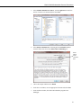
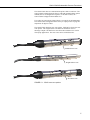
CS451/CS456 Submersible
Pressure Transducer
Revision: 1/13
C o p y r i g h t © 2 0 0 9 - 2 0 1 3
C a m p b e l l S c i e n t i f i c , I n c .
Warranty
“PRODUCTS MANUFACTURED BY CAMPBELL SCIENTIFIC, INC. are
warranted by Campbell Scientific, Inc. (“Campbell”) to be free from defects in
materials and workmanship under normal use and service for twelve (12)
months from date of shipment unless otherwise specified in the corresponding
Campbell pricelist or product manual. Products not manufactured, but that are
re-sold by Campbell, are warranted only to the limits extended by the original
manufacturer. Batteries, fine-wire thermocouples, desiccant, and other
consumables have no warranty. Campbell’s obligation under this warranty is
limited to repairing or replacing (at Campbell’s option) defective products,
which shall be the sole and exclusive remedy under this warranty. The
customer shall assume all costs of removing, reinstalling, and shipping
defective products to Campbell. Campbell will return such products by surface
carrier prepaid within the continental United States of America. To all other
locations, Campbell will return such products best way CIP (Port of Entry)
INCOTERM® 2010, prepaid. This warranty shall not apply to any products
which have been subjected to modification, misuse, neglect, improper service,
accidents of nature, or shipping damage. This warranty is in lieu of all other
warranties, expressed or implied. The warranty for installation services
performed by Campbell such as programming to customer specifications,
electrical connections to products manufactured by Campbell, and product
specific training, is part of Campbell’s product warranty. CAMPBELL
EXPRESSLY DISCLAIMS AND EXCLUDES ANY IMPLIED
WARRANTIES OF MERCHANTABILITY OR FITNESS FOR A
PARTICULAR PURPOSE. Campbell is not liable for any special, indirect,
incidental, and/or consequential damages.”
Assistance
Products may not be returned without prior authorization. The following
contact information is for US and international customers residing in countries
served by Campbell Scientific, Inc. directly. Affiliate companies handle
repairs for customers within their territories. Please visit
www.campbellsci.com to determine which Campbell Scientific company serves
your country.
To obtain a Returned Materials Authorization (RMA), contact CAMPBELL
SCIENTIFIC, INC., phone (435) 227-9000. After an applications engineer
determines the nature of the problem, an RMA number will be issued. Please
write this number clearly on the outside of the shipping container. Campbell
Scientific’s shipping address is:
CAMPBELL SCIENTIFIC, INC.
RMA#_____
815 West 1800 North
Logan, Utah 84321-1784
For all returns, the customer must fill out a “Statement of Product Cleanliness
and Decontamination” form and comply with the requirements specified in it.
The form is available from our web site at www.campbellsci.com/repair. A
completed form must be either emailed to [email protected] or faxed to
(435) 227-9106. Campbell Scientific is unable to process any returns until we
receive this form. If the form is not received within three days of product
receipt or is incomplete, the product will be returned to the customer at the
customer’s expense. Campbell Scientific reserves the right to refuse service on
products that were exposed to contaminants that may cause health or safety
concerns for our employees.
Table of Contents
PDF viewers: These page numbers refer to the printed version of this document. Use the
PDF reader bookmarks tab for links to specific sections.
1. Introduction .................................................................1
2. Cautionary Statements...............................................1
3. Initial Inspection .........................................................1
4. Quickstart ....................................................................2
4.1
4.2
4.3
4.4
4.5
4.6
Step 1 — Desiccant Check...................................................................2
Step 2 — Choose Appropriate Depth...................................................2
Step 3 — Dislodge Bubbles .................................................................3
Step 4 — Install Transducer.................................................................3
Step 5 — Measure Initial Water Elevation...........................................3
Step 6 — Use SCWin to Program Datalogger and Generate
Wiring Diagram................................................................................4
5. Overview......................................................................6
6. Specifications .............................................................8
7. Operation ...................................................................10
7.1
Configuration .....................................................................................10
7.1.1 PC Connection Using the A200 ..................................................10
7.1.1.1 Driver Installation ............................................................10
7.1.1.2 Wiring ..............................................................................10
7.1.1.3 Powering the Sensor.........................................................11
7.1.1.4 Determining which COM Port the A200 has been
Assigned .......................................................................11
7.1.2 Device Configuration Utility (version 2.03 or higher)................12
7.1.3 SDI-12 Transparent Mode ..........................................................12
7.1.4 RS-232 Connection via PC Terminal Software ..........................14
7.1.5 SDI-12 Commands......................................................................15
7.1.5.1 SDI-12 Addresses.............................................................16
7.1.5.2 Extended SDI-12 Commands ...........................................17
7.2
Installation Considerations.................................................................18
7.2.1 Non-Vertical Installations ...........................................................18
7.2.2 Offset Calculation .......................................................................18
7.2.3 Split Mesh Cable Grip (pn 25431) ..............................................19
7.3
Wiring ................................................................................................19
7.3.1 SDI-12.........................................................................................20
7.3.2 RS-232 ........................................................................................20
i
Table of Contents
7.4
Programming ..................................................................................... 20
7.4.1 CRBasic Programming............................................................... 21
7.4.1.1 Example Program for CR200(X)-Series Datalogger ....... 21
7.4.1.2 Example Program for CR1000 Datalogger..................... 22
7.4.2 Edlog Programming ................................................................... 22
7.4.2.1 Example Program for CR10(X) Dataloggers................... 23
8. Maintenance ..............................................................23
8.1
8.2
Every Visit......................................................................................... 24
Every Two to Three Years or on a Rotating Schedule ...................... 24
9. Troubleshooting........................................................24
Appendix
A. Calibration Certificate.............................................A-1
Figures
5-1.
7-1.
7-2.
7-3.
7-4.
7-5.
CS451 nose cone options..................................................................... 7
A200 Sensor-to-PC Interface............................................................. 11
Connect screen .................................................................................. 12
Terminal Emulator ............................................................................ 13
Terminal Emulator ............................................................................ 15
Transducer suspended with split mesh cable grip ............................. 19
7-1.
7-2.
7-3.
7-4.
7-5.
7-6.
7-7.
Factory Settings................................................................................. 10
A200 Wiring...................................................................................... 11
RS-232 Settings................................................................................. 14
RS-232 Terminal Commands ............................................................ 15
SDI-12 Commands ............................................................................ 16
SDI-12 Wiring................................................................................... 20
RS-232 Wiring .................................................................................. 20
Tables
ii
CS451/CS456 Submersible Pressure
Transducer
1.
Introduction
The CS451/CS456 Submersible Pressure Transducer provides pressure and
temperature measurements. It uses the SDI-12 or RS-232 communications
protocols to communicate with an SDI-12 or RS-232 recorder simplifying
installation and programming. The -L in the transducer’s model name
indicates user-specified cable length.
Before using the CS451/CS456 please study
•
•
•
2.
3.
Section 2, Cautionary Statements
Section 3, Initial Inspection
Section 4, Quickstart
Cautionary Statements
•
Sensor will be damaged if it is encased in frozen liquid.
•
Although the CS451/CS456 is rugged, it is also a highly precise scientific
instrument and should be handled as such. There are no user-serviceable
parts and any attempt to disassemble the device will void the warranty.
•
Care should be taken when opening the package not to damage or cut the
cable jacket.
•
Dropping the instrument or allowing it to “free fall” down a well may
damage the transducer.
•
Never suspend the CS451/CS456 from the connections at the top end of
the cable. Sharp bends or excessive pinching of the cable can cause
damage and may pinch off the vent tube causing measurement errors.
•
Confirm the compatibility of the sensor and cable to non-water
environments before installation.
•
The CS456 should be used in harsh water applications, including salt
water.
Initial Inspection
•
Upon receipt of the CS451/CS456, inspect the packaging for any signs of
shipping damage and, if found, report the damage to the carrier in
accordance with policy. The contents of the package should also be
inspected and a claim filed if any shipping related damage is discovered.
1
CS451/CS456 Submersible Pressure Transducer
4.
•
The model number and pressure range is etched on the housing and the
cable length is printed on the label near the connection end of the cable.
Check this information against the shipping documentation to ensure that
the expected product was received.
•
The transducer comes with a desiccant tube attached to the cable.
Quickstart
This quickstart guide assumes:
•
•
Default settings used (SDI-12 address 0, pressure reported in psig,
temperature reported in C)
ShortCut Program Generator for Windows (SCWin) used to program
datalogger, calculate offset, and generate wiring diagram
For complete configuration, installation, wiring, and programming information,
see Section 7, Operation.
4.1
Step 1 — Desiccant Check
CAUTION
The desiccant tube is shipped with a black cap to cover the
vent hole. This cap MUST be removed prior to installation.
Ensure the desiccant is blue; replace if not.
The desiccant tube must always be attached to the CS451/CS456.
4.2
Step 2 — Choose Appropriate Depth
The CS451/CS456 must be installed below the water at a fixed depth. This
depth should be chosen so the water pressure will never exceed the
transducer’s pressure range (twice its pressure range).
CAUTION
The output reading will not be correct, and the transducer
can be damaged if pressure is excessive (2 x full scale).
Pressure can be converted to feet of fresh water using the following simple
equation:
1 psi = 2.31 feet of water
For example, the maximum depth with a pressure range of 0 to 7.25 psig is
16.748 feet of water.
2
CS451/CS456 Submersible Pressure Transducer
4.3
Step 3 — Dislodge Bubbles
While submersing the transducer, air bubbles may become trapped between the
pressure plate and the water surface, causing small offset errors until the
bubbles dissolve. Dislodge these bubbles by gently shaking the CS451/CS456
while under water.
4.4
CAUTION
If bubbles are not removed by rotation and shaking
underwater (or bleeding out the air in a closed system), the
CS451/CS456 reading will drift lower by the distance of the
gap as the bubbles are slowly dissolved into the water over
time.
CAUTION
Hitting against the well casing or other solid surface could
damage the transducer.
Step 4 — Install Transducer
Lower the transducer to an appropriate depth.
CAUTION
Do not drop the instrument or allow it to “free fall” down a
well as this may damage the sensor.
With long drops it may be necessary to use the weighted nose cone (option
-WN).
The transducer body can be strapped with tie wraps or tape. Campbell
Scientific offers cable ties (pn 7421) that can be used to secure and strain relief
the cable. If installing in a well, fasten the cable to the well head. Wrap the
cable ties around the cable jacket.
CAUTION
Never suspend the CS451/CS456 from the connections at
the top of the cable. Sharp bends or excessive pinching of
the cable can cause damage and may pinch off the vent
tube causing measurement errors.
Several readings should be taken to ensure proper operations after installation.
4.5
Step 5 — Measure Initial Water Elevation
Use a staff gauge (or other device) to measure the initial elevation of water.
This value is used to calculate an offset that corrects the final measurement for
errors due to zero offset or installation. SCWin will make the offset
calculation. Refer to Section 7.2.2, Offset Calculation, if not using SCWin to
calculate the offset.
3
CS451/CS456 Submersible Pressure Transducer
4.6
Step 6 — Use SCWin to Program Datalogger and Generate
Wiring Diagram
The simplest method for programming the datalogger to measure a
CS451/CS456 is to use SCWin.
4
1.
Open Short Cut and click on New Program then select Next.
2.
Select a datalogger and scan interval then select Next.
CS451/CS456 Submersible Pressure Transducer
3.
Select CS451/CS456 Pressure Sensor, click the right arrow to add it to
the list of sensors to be measured, then select Next.
4.
Select Offset Calculation then select lvl_ft for the Linked Level and
enter the initial water level in the Observed Level Reading box.
Enter
initial
water
elevation
here
5.
Choose the outputs and then select Finish.
6.
In the Save As window, enter an appropriate file name and select Save.
7.
In the Confirm window, click Yes to download the program to the
datalogger.
5
CS451/CS456 Submersible Pressure Transducer
8.
NOTE
5.
Click on Wiring Diagram and wire according to the wiring diagram
generated by SCWin Short Cut.
Refer to Section 7, Operation, for wiring, offset calculation, and
programming information if not using SCWin Short Cut.
Overview
The CS451/CS456 Submersible Pressure Transducer is designed to provide a
reliable, accurate pressure/level measurement that is fully temperature
compensated.
The 24 bit A/D has simultaneous 50/60 Hz rejection and automatic calibration
for each measurement. A number of additional advanced measurement
techniques are employed to harness the best possible performance available from
today’s state-of-the-art pressure transducer technology. The transducer reverts to
a low power sleep state between measurements. A series of measurements are
performed yielding a temperature and pressure value. This measurement cycle
takes less than 1.5 second. The transducer can also be configured to output
pressure only in less than 1 second. The measurement cycle is activated by
commands via SDI-12 or RS-232 terminal commands.
The design uses a piezoresistive sensor housed in a 316L stainless-steel (CS451)
or titanium (CS456) package to enhance reliability. The rugged construction
makes the CS451/CS456 suitable for water level measurement in irrigation
applications, water wells, lakes, streams and tanks. The titanium package of the
CS456 makes it ideal for salt water or other harsh environments. The cable
incorporates a vent tube to compensate for atmospheric pressure fluctuations and
the jacket is made of rugged Hytrel®, designed to remain flexible and tough,
even under harsh environmental conditions.
6
CS451/CS456 Submersible Pressure Transducer
The CS451/CS456 has two communication options: SDI-12 or RS-232. The
CS451/CS456 is shipped from the factory with both communications options
enabled; there is no configuration required. As an SDI-12 sensor, the
CS451/CS456 is shipped with an address of 0.
Two values are output by the CS451/CS456—pressure/level and temperature.
The CS451/CS456 is shipped from the factory to output pressure in psig and
temperature in degrees Celsius.
The CS451/CS456 has three nose cone options. FIGURE 5-1 shows the nose
cone options. The weighted nose cone makes the transducer easier to
submerge to depth. The NPT nose cone allows the transducer to be used in
closed-pipe applications. The nose cones can be switched out later.
Standard Nose Cone
Weighted Nose Cone
NPT Nose Cone
FIGURE 5-1. CS451 nose cone options
7
CS451/CS456 Submersible Pressure Transducer
6.
Specifications
Features:
• Output acceptable for recording devices with SDI-12 or RS-232
capability including Campbell Scientific dataloggers
• Quality construction that ensures product reliability
• Rugged stainless steel or titanium case that protects piezoresistive
sensor
• Fully temperature compensated
• Low power sleep state between measurements that reduces power
consumption
• Weighted nose cone offered that adds 0.2 kg (7.4 oz) to the
transducer’s weight. Additional weight makes submersion of the
transducer easier
Compatible Dataloggers:
CR200(X) series
CR800
CR850
CR1000
CR3000
CR5000
CR500
CR510
CR10(X)
CR23X
Power Requirements:
5 to 18 Vdc
Power Consumption:
Quiescent current < 50 µA
Measurement/Communication Current: 8
mA for 1-s measurement
Maximum Peak Current: 40 mA
Measurement Time:
Less than 1.5 s
Outputs:
SDI-12 (version 1.3) 1200 bps
RS-232 9600 bps
Measurement Ranges:
8
Pressure (psig)
Pressure (kPa)
Depth of fresh water
0 to 2.9
0 to 20
0 to 2 m (6.7 ft)
0 to 7.25
0 to 50
0 to 5.1 m (16.7 ft)
0 to 14.5
0 to 100
0 to 10.2 m (33.4 ft)
0 to 29
0 to 200
0 to 20.4 m (67 ft)
0 to 72.5
0 to 500
0 to 50.9 m (167 ft)
0 to 145
0 to 1000
0 to 102 m (334.5 ft)
Accuracy:
±0.1% full scale range TEB* or
±0.05% full scale range TEB**
Resolution:
0.0035% full scale range
CS451/CS456 Submersible Pressure Transducer
CAUTION
Overpressure:
2x pressure range
Dry Storage Temperature:
─10° to 80°C
Sensor will be damaged if it is encased in frozen liquid.
Operating Temperature:
0° to 60°C
Temperature Accuracy:
±0.2°C
Maximum Cable Length:
SDI-12 (one transducer
connected to a single port): ~475 m (1500 ft)
SDI-12 (10 transducers
connected to a single port): 60 m (200 ft)
RS-232:
60 m (200 ft)
Cable Type:
5 Conductor, 26 AWG
Hytrel Jacket
Body Material:
CS451 – 316L Stainless Steel
CS456 – Titanium
Element Material:
CS451 – 316L Stainless Steel
CS456 – Hastelloy
Top Cone Material:
Delrin
Dimensions:
Length 213.36 mm (6.875 in)
Diameter 21.34 mm (0.84 in)
Distance from pressure sensor interface
(black line etched on housing) to:
End of NPT fitting:
2.54 cm (1 in)
End of standard nose cone:
2.3 cm (0.9 in)
End of weighted nose cone:
9.9 cm (3.9 in)
Air Gap
Standard and weighted
nose cone:
NPT fitting:
Weight:
25431 Split Mesh Grip
Accepts cable diameter:
Breaking Strength:
0.653 cm (0.257 in)
2.72 cm (1.07 in)
CS451: 0.17 kg (0.37 lb)
CS456: 0.10 kg (0.23 lb)
Cable: 0.421 kg/m (0.283 lb/ft)
4.57 to 6.35 mm (0.18 to 0.25 in)
~300 lb
* Total Error Band (TEB) includes the combined errors due to nonlinearity,
hysteresis, nonrepeatability, and thermal effects over the compensated
temperature range, per ISA S51.1.
** 0.05% full scale range accuracy not available in the 0 to 2.9 psig range.
9
CS451/CS456 Submersible Pressure Transducer
7.
Operation
7.1
Configuration
The CS451/CS456 is configured at the factory with default settings:
TABLE 7-1. Factory Settings
SDI-12 Address
0
RS-232 Baud Rate
9600
Pressure/Level Units
PSIG
Temperature Units
Celsius
Communicating with the CS451/CS456 requires the sensor to be either
connected to a PC or to an SDI-12 recorder. The sensor typically connects to a
PC via the A200 sensor to PC interface. Many SDI-12 recorders allow
communication to the sensor via a terminal screen. Configurable settings can
be changed via SDI-12 commands or by using Campbell Scientific’s software
Device Configuration Utility.
7.1.1 PC Connection Using the A200
The A200 or another device is required to connect the CS451/CS456 to a PC.
This allows sensor settings to be changed via our Device Configuration Utility.
7.1.1.1 Driver Installation
If the A200 has not been previously plugged into your PC and your PC
operating system is not Windows 7, the A200 driver needs to be loaded onto
your PC.
NOTE
Drivers should be loaded before plugging the A200 into the PC.
The A200 drivers can be downloaded, at no charge, from:
www.campbellsci.com/downloads.
7.1.1.2 Wiring
One end of the A200 has a terminal block while the other end has a type B
female USB port. The terminal block provides 12V, G, TX, and RX terminals
for connecting the sensor (see FIGURE 7-1 and TABLE 7-2).
A data cable (pn 17648) ships with the A200. This cable has a USB type-A
male connector that attaches to a PC’s USB port, and a type B male connector
that attaches to the A200’s USB port.
10
CS451/CS456 Submersible Pressure Transducer
7.1.1.3 Powering the Sensor
The A200 provides power to the sensor when it is connected to a PC’s USB
port. An internal DC/DC converter boosts the 5 Vdc supply from the USB
connection to a 12 Vdc output is required to power the sensor.
7.1.1.4 Determining which COM Port the A200 has been Assigned
When the A200 driver is loaded, the A200 is assigned a COM port number.
This COM port number is needed when using the Device Configuration Utility
or a PC terminal software such as HyperTerminal.
Often, the assigned COM port will be the next port number that is free.
However, if other devices have been installed in the past (some of which may
no longer be plugged in), the A200 may be assigned a higher COM port
number.
To check which COM port has been assigned to the A200, watch for the
appearance of a new COM port in the list of COM ports offered in the software
package (e.g., LoggerNet) before and after the installation, or look in the
Windows Device Manager list under the ports section (access via the control
panel).
FIGURE 7-1. A200 Sensor-to-PC Interface
TABLE 7-2. A200 Wiring
Color
Sensor
Cable Label
A200
Terminal
Red
12V
+12Vdc
Black
G
G
White
C
Tx
Blue
G
Rx
Yellow
G
G
Clear
Signal Ground
G
11
CS451/CS456 Submersible Pressure Transducer
7.1.2 Device Configuration Utility (version 2.03 or higher)
The Device Configuration Utility allows you to change the settings of the
CS451/CS456. Device Configuration Utility is shipped on the Campbell
Scientific ResourceDVD included with the CS451/CS456.
To use Device Configuration Utility, the transducer needs to be connected to
the PC via the A200 (see Section 7.1.1, PC Connection Using the A200). After
installing Device Configuration Utility and connecting the transducer to the
PC, select CS451 from the Device Type list on the left column of the screen.
In the PC Serial Port box, select the COM port that was assigned to the A200
(see Section 7.1.1.4, Determining which COM Port the A200 has been
Assigned). Click on the Connect button to enable communication with the
sensor. Once successfully connected, the screen should look like FIGURE 7-2.
FIGURE 7-2. Connect screen
There are three settings that can be changed: SDI-12 address, Pressure/Level
Units and Temperature Units. Double-click on the window of the units to be
changed. This will open a pick menu box. Select the desired units and Apply
the changes.
7.1.3 SDI-12 Transparent Mode
Transparent Mode allows direct communication with the CS451/CS456. This
may require waiting for programmed datalogger commands to finish before
sending responses. While in the transparent mode, datalogger programs may
not execute. Datalogger security may need to be unlocked before transparent
mode can be activated.
12
CS451/CS456 Submersible Pressure Transducer
Transparent mode is entered while the PC is in telecommunications with the
datalogger through a terminal emulator program. It is most easily accessed
through Campbell Scientific datalogger support software, but is also accessible
with terminal emulator program.
To enter the SDI-12 transparent mode, enter Terminal Emulator from
LoggerNet, PC400 or PC200W datalogger support software. A terminal
emulator screen is displayed. Click the Open Terminal button.
For CR800-series, CR1000, CR3000 dataloggers, press <Enter> until the
datalogger responds with the prompt (“CR800>” for the CR800). Type SDI12
at the prompt and press <Enter>. In response, the query Enter Cx Port 1,3,5
or 7 will appear. Enter the control port integer to which the transducer is
connected. An Entering SDI12 Terminal response indicates that SDI-12
Transparent Mode is active.
FIGURE 7-3. Terminal Emulator
For CR10X and CR510 standard mixed-array dataloggers, the
telecommunications command to enter SDI-12 transparent mode is nX<Enter>
where n is the control port being used for SDI-12. In this example, the selected
control port is C1, so the command would be 1X<Enter>. In response, the
datalogger opens the link to control port 1 and responds with a prompt. CR10X
and CR510 dataloggers reply with entering SDI-12.
CR10X-PB and CR510-PB dataloggers require *#n being entered at the
prompt, where n is the control port being used.
13
CS451/CS456 Submersible Pressure Transducer
Now check for response from the sensor with address zero by typing the SDI12 Identify command 0I!<Enter> (that’s a zero, not the letter O). The sensor
should respond with an identification string similar to:
013CSI450.Std.01_xxxxxxxx, where xxxxxxxx represents the eight digit serial
number. Note that the SDI-12 standard allows for multiple probes to be
connected to one datalogger control port. For example, if you have another
SDI-12 probe on the C1 that has address 7, you could issue the identify
command 7I!<Enter>.
Only one sensor of the same address can be connected when using the change
address command.
7.1.4 RS-232 Connection via PC Terminal Software
PC terminal software can be used to communicate with the CS451/CS456 via
the RS-232 communication mode (see FIGURE 7-4).
The CS451/CS456 is connected to the PC via the A200 (see Section 7.1.1, PC
Connection Using the A200).
Upon setup, the terminal emulator software will request you enter the
Communication connection; defaults to a phone connection. Change the
communication to appropriate “Com” in the “Connect Using” box (see Section
7.1.1.4, Determining which COM Port the A200 has been Assigned, to
determine the COM port that was assigned to the A200). The software will
then prompt for the proper “Port Settings”. TABLE 7-3 shows the RS-232
settings.
TABLE 7-3. RS-232 Settings
Bits per Second
9600
Data bits
8
Parity
None
Stop bits
1
Flow control
None
You will now be able to communicate with the CS451/CS456. At the prompt,
push the <Enter> key several times. This will wake-up the RS-232 mode of
the sensor. TABLE 7-4 shows the RS-232 commands that can be entered once
it is in the RS-232 mode.
NOTE
14
By default, the CS451/CS456 is in the SDI-12 mode for
communication. Once in the RS-232 mode, if there is no
communication for 20 seconds, the sensor will return to the SDI12 mode.
CS451/CS456 Submersible Pressure Transducer
FIGURE 7-4. Terminal Emulator
TABLE 7-4. RS-232 Terminal Commands
Terminal Commands
Values Returned
1
Serial Number, Pressure/Level, Temperature
(in configured units)
2
Serial Number, Pressure (kPa), Temperature
(°C)
3
Serial Number, ΔR(ohms), Rb(ohms),
Temperature (°C), Element Serial Number,
Product Name
5
Copyright information, OS Version and Date,
Serial Number, Element Serial Number,
Product Name, User Defined Name (Station
Name), SDI-12 Address
H or h
Help menu
7.1.5 SDI-12 Commands
The CS451/CS456 uses an SDI-12 compatible hardware interface and supports
a subset of the SDI-12 commands. The most commonly used command is the
aM! command, issued by the datalogger, where a represents the sensor address.
The communication sequence begins with the datalogger waking the sensor
and issuing the aM! command. The transducer responds to the datalogger
indicating that two measurements will be ready within two seconds.
Subsequent communications handle data reporting from the sensor to the
datalogger.
The SDI-12 protocol has the ability to support various measurement
commands. The CS451/CS456 supports the commands that are listed in
TABLE 7-5.
15
CS451/CS456 Submersible Pressure Transducer
TABLE 7-5. SDI-12 Commands
SDI-12 Command
Command Function
Values Returned
aM!
Configured settings
Pressure/Level,
Temperature
aM1!
PSIG, °C
Pressure, Temperature
aM2!
PSIG, °F
Pressure, Temperature
aM3!
kPa, °C
Pressure, Temperature
aM4!
kPa, °F
Pressure, Temperature
aM5!
Sensor’s Serial Number
Serial Number
aM6!
Ohms, ohms, °C
ΔR, Rb, Temperature
aM7!
Configured settings
(provides data in less than
0.8 seconds)
Pressure/Level
aM8!
Configured settings
(provides average of data
based on user selected
samples)
Pressure/Level,
Temperature
As measurement data is transferred between the probe and datalogger digitally,
there are no offset errors incurred with increasing cable length as seen with
analog sensors. However, with increasing cable length, there is still a point
when digital communications break down, resulting in either no response or
excessive SDI-12 retries and incorrect data due to noise problems. (Using SDI12 commands like aMC!, which adds a CRC check, can significantly improve
incorrect data issues.)
7.1.5.1 SDI-12 Addresses
Multiple sensors can be connected to a single digital I/O channel (control port)
on an SDI-12-compatible datalogger; each sensor must have a unique SDI-12
address. Possible addresses are 0 to 9, A to Z, and a to z.
The CS451/CS456 is shipped from the factory with the address set to 0. The
address on the CS451/CS456 can be changed by sending an SDI-12 change
address command ‘aAb!’, where a is the original address and b is the new
address. The change address command can be issued from most SDI-12
recorders.
To change the address of a sensor that has a default address of 0 to the address
of 1 the following command can be sent:
0A1!
When it is necessary to measure more than one CS451/CS456, it is easiest to
use a different control port for each CS451/CS456 instead of changing the
16
CS451/CS456 Submersible Pressure Transducer
address. If additional control ports are not available, then the address will need
to be changed.
7.1.5.2 Extended SDI-12 Commands
Extended SDI-12 commands can be used to configure the CS451/CS456 data
output and sample number. These commands are used to select the
temperature units (Celsius or Fahrenheit), pressure/level units (psig, kPa, bar,
feet, meter, inches, or millimeter), and the integration time for each
measurement. If level units are selected, they will represent level of fresh
water. The multiplier (slope) and offset should be used to correct for relative
density of water.
Sample number represents the number of values used to provide the output
value received by the datalogger. This output value is an average of the
samples.
The extended SDI-12 command used to configure output units is
aXCONFIG1=tt,pp,mmm.mm,000.00! where a = the SDI-12 address of the
sensor, tt = temperature units, pp = measurement unit, mmm.mm = multiplier
(slope), and 000.00 = offset.
Valid entries for tt (temperature) are:
0 = Celsius
1 = Fahrenheit
and valid entries for pp (pressure/level) are:
0 = psig
1 = kPa
2 = Bar
3 = Feet
4 = Meter
5 = Inch
6 = Millimeter
Only SDI-12 instruction aM!, aM7!, and aM8! output the results obtained
when using the multiplier and offset. The multiplier and offset are only applied
to the pressure/level value, not to the temperature.
The extended SDI-12 command used to configure sample number is
aXCONFIG2=nnn!, where nnn is the number of samples that will be measured
to obtain the final output value, which is an average of the samples taken. This
value only applies to the aM8! command. The integration time is a result of
the number of samples selected. This value can be derived by adding 2 s to the
number of samples. For example, if nnn = 50, then 50 samples would be
averaged. The integration time for this process is 50 plus 2, or 52 s.
17
CS451/CS456 Submersible Pressure Transducer
7.2
Installation Considerations
The CS451/CS456 is designed for water level measurements. Typical
applications include agricultural water level/flow, water wells, lakes, streams
and tanks. If the device is to be installed in a liquid other than water or in
contaminated water, check the compatibility of the wetted material. The
CS456 should be used in harsh water applications, including salt water.
7.2.1 Non-Vertical Installations
The CS451/CS456 can be installed in any position; however, when it leaves the
factory it is tested in the vertical position. There will be an offset error if not
installed vertically; contact Campbell Scientific for more information.
Strapping the transducer body with tie wraps or tape will not hurt it.
7.2.2 Offset Calculation
The pressure created is directly proportional to the water column above the
sensor. An offset is used to correct the final measurement to any error due to
sensor zero offset or installation.
For example, if the correct elevation of the water, as measured by a staff gauge
or other measurement device, is 2015.50 feet, and the CS451 provides a
reading of 5.76 psig, then:
5.76 psig * 2.31 ft/psig = 13.3056 ft.
So, the offset is calculated:
2015.50 ft – 13.3056 ft = 2002.1944 ft
This offset can be accounted for in the program instruction of the SDI-12
recorder.
18
CS451/CS456 Submersible Pressure Transducer
7.2.3 Split Mesh Cable Grip (pn 25431)
The 25431 Split Mesh Cable Grip is recommended for use in wells to center
the cable and to provide a method of suspending the cable-reducing cable
stretch. FIGURE 7-5 shows a transducer’s cable suspended using the split
mesh cable grip.
FIGURE 7-5. Transducer suspended with split mesh cable grip
7.3
Wiring
NOTE
Power down your system before wiring the CS451/CS456. The
shield wire plays an important role in noise emissions and
susceptibility as well as transient protection.
19
CS451/CS456 Submersible Pressure Transducer
7.3.1 SDI-12
TABLE 7-6. SDI-12 Wiring
Color
CS451/CS456
Function
CR800
CR5000
CR3000
CR1000
CR200(X)
Series
CR510
CR23X
CR10X
Red
+12VDC
12V
Battery+
12V
Black
Power Ground
G
G
G
White
SDI-12 Signal
*Control Port
C1/SDI-12
Control Port
Blue
GND
GND
G
G
Yellow
GND
GND
G
G
Clear
Shield
GND
G
G
*dedicated SDI-12 port on CR5000
7.3.2 RS-232
TABLE 7-7. RS-232 Wiring
7.4
Color
CS451/CS456
Function
Connection
Red
+12vdc
Power Source
Black
Power Ground
Power Ground
White
RS-232 Tx (Output)
Transmit
Pin 2 Rx (Input)
Blue
RS-232 Rx (Input)
Receive
Pin 3 Tx (Output)
Yellow
Digital Ground
Ground
Pin 5 GND
Clear
Shield GND
Ground
RS-232 9-pin
Programming
NOTE
SCWin is the preferred method for programming the datalogger.
SCWin generates a wiring diagram that shows how to connect
the CS451/CS456 to your Campbell Scientific datalogger. This
section is for users who are using CRBasic or Edlog to program
their datalogger.
NOTE
The sections that immediately follow are for CRBasic and Edlog.
Keyboard/Display users and SCWin users can jump ahead to the Maintenance
section.
20
CS451/CS456 Submersible Pressure Transducer
7.4.1 CRBasic Programming
Dataloggers that use CRBasic include our CR200(X)-series, CR800, CR850,
CR1000, CR3000, and CR5000. These dataloggers use the SDI12Recorder()
to read the CS451/CS456. A multiplier of 1.0 and an offset of 0.0 yield water
level in psig and temperature in degrees C.
The SDI12Recorder() instruction has the following form:
SDI12Recorder(Destination, Output String, Multiplier, Offset)
7.4.1.1 Example Program for CR200(X)-Series Datalogger
'CR200(X) Series
'Declare the variable for the water level measurement
Public CS451(2)
'Rename the variable names
Alias CS451(1)=Level
Alias CS451(2)=Temp_C
'Define a data table for 60 minute maximum and minimums
DataTable(Hourly,True,-1)
DataInterval(0,60,Min)
Maximum(1,Level,0,0)
Minimum(1,Level,0,0)
Maximum(1,Temp_C,0,0)
Minimum(1,Temp_C,0,0)
EndTable
'Read sensor every 60 seconds
BeginProg
Scan(60,sec)
'Code for SDI-12 measurements:
SDI12Recorder(CS451,0M!,1,0)
'Call the data table:
CallTable(Hourly)
NextScan
EndProg
21
CS451/CS456 Submersible Pressure Transducer
7.4.1.2 Example Program for CR1000 Datalogger
'CR1000 Series Datalogger
'Declare the variable for the water level measurement
Public CS451(2)
'Rename the variable names
Alias CS451(1)=Level
Alias CS451(2)=Temp_C
'Define a data table for 60 minute maximum and minimums
DataTable(Hourly,True,-1)
DataInterval(0,60,Min,10)
Maximum(1,Level,FP2,0,0)
Minimum(1,Level,FP2,0,0)
Maximum(1,Temp_C,FP2,0,0)
Minimum(1,Temp_C,FP2,0,0)
EndTable
'Read sensor every 60 seconds
BeginProg
Scan(60,sec,1,0)
'Code for SDI-12 measurements:
SDI12Recorder(CS451,1,”0”,”M!”,1,0)
'Call the data table:
CallTable(Hourly)
NextScan
EndProg
7.4.2 Edlog Programming
Our CR500, CR510, CR10(X), and CR23X dataloggers are programmed with
Edlog.
These dataloggers use Instruction 105 to read the CS451/CS456. Your
datalogger manual has a detailed explanation of Instruction 105.
Please note that Edlog only allocates one input location for Instruction 105.
Two input locations are required—one for the pressure measurement and one
for the temperature measurement. The additional input location needs to be
inserted manually using the Input Location Editor. To get into the Input
Location Editor, select Edit/Input Labels or press the F5 key. Once in the Input
Location Editor, do the following steps:
22
1.
Choose Edit/Insert Block.
2.
After the Insert Block dialog box appears, type in a base name for the
input locations. Each input location will have the base name with an
underscore and a consecutive number.
3.
In the Start Address field, type in the number of the first input location.
4.
In the Number of InLocs field, type in 2 and select OK.
CS451/CS456 Submersible Pressure Transducer
7.4.2.1 Example Program for CR10(X) Dataloggers
Below is a portion of a CR10X program that measures the CS451/CS456.
NOTE
The instructions below do not store data in final storage.
Instruction 92, Instruction 77 and processing instructions such as
Instruction 70 are required to store the data permanently.
;{CR10X}
;
*Table 1 Program
01: 60
Execution Interval (seconds)
1: SDI-12 Recorder (P105)
1: 0
SDI-12 Address
2: 0
Start Measurement (aM0!)
3: 1
Port ;this is where the white wire is connected
4: 1
Loc[Data_1
]
5: 1.0
Mult
6: 0.0
Offset
*Table 2 Program
02: 0.000
Execution Interval (seconds)
*Table 3 Subroutines
End Program
After Instruction 105 is executed, the input location called “Data_1” will hold
the measured pressure, reported in PSI, and the input location called Data_2
will hold the measured temperature, in degrees Celsius. The results can be
further processed by the datalogger. Note that Port 1 specifies that the SDI-12
data line is to be connected to the Port C1.
8.
Maintenance
Campbell Scientific recommends that the CS451/CS456 be factory recalibrated
and checked every 24 months. Before a CS451/CS456 sensor is sent to
Campbell Scientific, the customer must get an RMA (returned material
authorization) number, and fill out the Declaration of Hazardous Material and
Decontamination form.
The CS451/CS456 has no user-serviceable parts. Cable can be damaged by
abrasion, rodents, sharp objects, twisting, crimping or crushing, and pulling.
Take care during installation and use to avoid cable damage. If a section of
cable is damaged, it is recommended that you send your sensor back to replace
the bale harness assembly.
Periodic evaluation of the desiccant is vital for keeping the vent tube dry. The
CS451/CS456 ships with the desiccant tube attached. To assess the
effectiveness of the desiccant, use one of the following:
23
CS451/CS456 Submersible Pressure Transducer
8.1
8.2
•
The desiccant in the tube changes color from blue to pink when the drying
power is lost.
•
The Enclosure Accessory Humidity Indicator Card (pn 28878).
Every Visit
•
Collect data
•
Visually inspect wiring and physical conditions
•
Check indicating desiccant or enclosure humidity indicator; service if
necessary
•
Check battery condition (inspect physical appearance and use a keyboard
display, PDA, or laptop to view the battery voltage)
•
Check all sensor readings: adjust transducer offsets if necessary
•
Check recent data
Every Two to Three Years or on a Rotating Schedule
•
9.
Send the CS451/CS456 in for inspection.
Troubleshooting
The most common causes for erroneous pressure transducer data include:
•
poor sensor connections to the datalogger
•
damaged cables
•
damaged transducers
•
moisture in the vent tube
Problem:
Unit will not respond when attempting serial communications.
Suggestion:
Check the power (red is +V and black is ground) and signal (white is SDI-12
data) lines to ensure proper connection to the datalogger. Check the datalogger
program to ensure that the same port the SDI-12 data line is connected to is
specified in the measurement instruction.
Problem:
Transducer appears to be operating properly but data shows a periodic or cyclic
fluctuation not attributable to water level changes.
24
CS451/CS456 Submersible Pressure Transducer
Suggestion:
A kinked or plugged vent tube will not effectively vent a gauge pressure
(Vented) type of device. Normal changes in barometric pressure will appear as
water level fluctuations and these types of errors are typically on the order of 1
foot of water level. If the desiccant chamber has not been properly maintained,
water may have condensed in the vent tube and the device should be returned
to the factory for service.
25
CS451/CS456 Submersible Pressure Transducer
26
Appendix A. Calibration Certificate
Each CS451/CS456 has been calibrated to meet printed accuracy specification
at multiple temperature and pressure ranges. If additional verification is
required, a Calibration Certificate can be purchased for each CS451/CS456
Submersible Pressure Transducer.
The Instrument Data Report provides a list of the pressure and temperature at
which the sensor was tested.
Pressure [kPa] is the pressure applied (listed in kilopascals) to the sensor.
Temperature [°C] is the temperature inside the test chamber at the time of
testing. Pressure After [kPa] represents the resulting measurement output by
the CS451/CS456 at the give pressure and temperature. Finally, Deviation
After [%F.S.], provides the difference between the actual pressure applied to
the sensor and the pressure measurement output by the sensor. This value is
listed as a percentage of the Full Scale range of the sensor.
When a CS451/CS456 is returned to Campbell Scientific for calibration, the
sensor will be returned with an Instrument Data Report. This report will
include values in the Pressure Before [kPa] column. These values represent the
measured pressure the sensor returns at the specified pressure and temperature,
BEFORE calibration.
A-1
Appendix A. Calibration Certificate
A-2
Campbell Scientific Companies
Campbell Scientific, Inc. (CSI)
815 West 1800 North
Logan, Utah 84321
UNITED STATES
www.campbellsci.com • [email protected]
Campbell Scientific Africa Pty. Ltd. (CSAf)
PO Box 2450
Somerset West 7129
SOUTH AFRICA
www.csafrica.co.za • [email protected]
Campbell Scientific Australia Pty. Ltd. (CSA)
PO Box 8108
Garbutt Post Shop QLD 4814
AUSTRALIA
www.campbellsci.com.au • [email protected]
Campbell Scientific do Brazil Ltda. (CSB)
Rua Luisa Crapsi Orsi, 15 Butantã
CEP: 005543-000 São Paulo SP BRAZIL
www.campbellsci.com.br • [email protected]
Campbell Scientific Canada Corp. (CSC)
11564 - 149th Street NW
Edmonton, Alberta T5M 1W7
CANADA
www.campbellsci.ca • [email protected]
Campbell Scientific Centro Caribe S.A. (CSCC)
300 N Cementerio, Edificio Breller
Santo Domingo, Heredia 40305
COSTA RICA
www.campbellsci.cc • [email protected]
Campbell Scientific Ltd. (CSL)
Campbell Park
80 Hathern Road
Shepshed, Loughborough LE12 9GX
UNITED KINGDOM
www.campbellsci.co.uk • [email protected]
Campbell Scientific Ltd. (France)
3 Avenue de la Division Leclerc
92160 ANTONY
FRANCE
www.campbellsci.fr • [email protected]
Campbell Scientific Spain, S. L.
Avda. Pompeu Fabra 7-9, local 1
08024 Barcelona
SPAIN
www.campbellsci.es • [email protected]
Please visit www.campbellsci.com to obtain contact information for your local US or international representative.