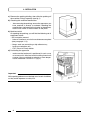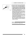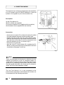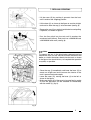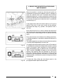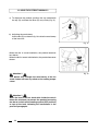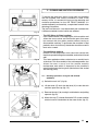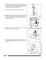
1
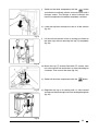
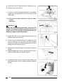
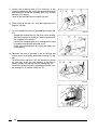
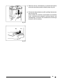
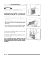
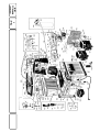
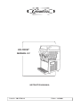
ICE FROST
MANUAL 2.2
INSTRUCTION MANUAL
Code Nr. : IMI I F M 2.2
Edition : 01/2003
Dear Client,
we would like to congratulate you for having chosen a high
quality product which will surely meet all your expectations.
While thanking you for the preference you have given us,
we invite you to carefully read the following instruction
manual before operating your ICE FROST MANUAL 2.2
slush machine.
1
INDEX
1
2
3
IMPORTANT WARNINGS AND
SUGGESTIONS
page 3
TECHNICAL CHARACTERISTICS
page 3
2.1
page 3
Specification plate
INSTRUCTIONS FOR MACHINE
TRANSPORT
page 3
4
INSTALLATION
page 4
5
CONNECTION TO POWER SUPPLY
MAINS
page 5
6
CONNECTION DIAGRAM
page 6
7
REFILLING OPERATIONS
page 7
8
START-UP PROCEDURES
page 8
8.1
Explanation of the controls and
their use (manual mode)
page 8
Setting the "ice-slush drinks" and
"cold drinks" functions"
page 8
Variations in the time display
(twenty-four or twelve hour clock)
and the temperature display
(°C or °F)
page 10
DEVICES FOR THE PROTECTION OF
PERSONNEL AND THE MACHINE
page 11
8.2
8.3
9
10 USING ICE FROST MANUAL 2.2
page 12
11 CLEANING AND SANITATION
PROCEDURES
page 13
11.1 Cleaning operations using the
CIP method:
(WEEKLY)
page 13
11.2 Cleaning and sanitising operations
using the normal method
(MONTHLY)
page 16
12 SPECIAL MAINTENANCE
2
page 20
1 - IMPORTANT WARNINGS AND SUGGESTIONS
The present instruction manual is an important part of
the ICE FROST MANUAL 2.2 slush machine and must
be kept for any future consultation.
Carefully read the warnings contained in this instruction
manual before installing and operating the ICE FROST
MANUAL 2.2 slush machine.
Besides providing information on routine maintenance
of the slush machine and aiding the technical assistants
in the detection and repair of possible malfunctions,
the objective of this manual is to take advantage of the
maximum potentials of the ICE FROST MANUAL 2.2
slush machine in order to adapt the machine to the
specific needs of the various countries where it will be
used.
Modification of, or any attempt to modify this machine,
is extremely dangerous and will cancel any form of
warranty.
All maintenance procedures must be performed by
expertly qualified personnel. The attempt to repair the
machine by unqualified persons is dangerous and may
cause serious damage to the machine.
2 - TECHNICAL CHARACTERISTICS
2.1
Specification plate
The voltage and frequency rates are found on the
specification plate.
3 - INSTRUCTIONS FOR MACHINE TRANSPORT
In order to prevent the oil contained in the compressor from
flowing into the cooling circuit, it is necessary to always carry,
store and handle the slush machine in a vertical position,
following the instructions found on the packaging.
The special wooden pallet, equipped with fork-lift slots, allow
the machine to be moved with common handling and lifting
equipment.
3
4 - INSTALLATION
a) Remove the packing binding, then slide the packing off
the machine, lifting it upwards (see fig.1).
b) Checking the machine identification
- after removing the packing, ensure the apparatus you
have received is exactly as ordered, checking the
specifications indicated on the invoice or the delivery
note are the same as those written on the plate.
b) Machine tool kit
On opening the packing, you will find the following set of
equipment inside:
- this instruction manual;
- 1 tube of Vaseline to use for the maintenance required
(see paragraph 11.2);
- 2 bags, each one containing a drip collector tray;
- 1 pressure reduction unit;
- 1 CIP (Clean In Place) device.
d) Positioning the apparatus
- make sure the bodywork is positioned in such a way
as to ensure it is aired and avoid installing it near heat
sources. You are advised to maintain a room temperature of between 15 and 25 °C (fig. 2).
Fig. 1
Important
All the packing element must be kept out of reach of children
as they could represent a safety risk.
Fig. 2
4
5 - CONNECTION TO POWER SUPPLY MAINS
Fig. 3
For your personal safety, before inserting the plug into
the electrical outlet, as previously explained in
paragraph 4, carefully read the following precautions:
- The electrical safety of the ICE FROST MANUAL 2.2
slush machine can only be achieved if the machine
is properly connected to an efficient grounding
system, in compliance with current national safety
standards. Therefore, the manufacturer cannot be held
responsible for damage and/or injury caused by
failure to properly ground the machine.
- For a safe and correct installation, it is necessary to
provide for a special outlet, with contacts having an
open distance equal to or greater than 3 mm, controlled
by an unipolar circuit breaker, conforming to current
national security standards (see fig. 3).
- The power supply cable must not, in any way, for its
entire length, be compressed, extension cords may
not be used, and finally, the plug must be removed
from the outlet with a slight pulling movement, after
having first cutoff the power supply.
- Do not obstruct the ventilating grill and heat dispersion
grill, since an insufficient ventilation may not only
reduce the efficiency of the machine, causing it to
function inadequately, but may also cause serious
damage to the machine.
Important
If the power supply cable is damaged, to prevent risks of any
kind, it must be replaced by qualified personnel.
5
6 - CONNECTION DIAGRAM
The diagram in fig. 4 shows the sequence for the connection
of a CO2 cylinder to the ICE FROST MANUAL 2.2 (the said
cylinder is not supplied as part of the machine’s kit).
Description:
(A) Ice Frost Manual 2.2
(B) CO2 cylinder (not supplied)
(C) Pressure reduction unit (supplied with the machine)
(D) Connection hose (supplied with the machine)
Fig. 4
Connection:
- remove the rear panel (E) to release the hose (D) coiled
up inside between the panel and the machine itself;
- connect one end of the hose (D) to the solenoid valves,
fitted with quick couplings and located inside the machine.
- The other end of the hose (D) must be connected to the
pressure reduction unit (C), as shown in fig. 5;
- remount the rear panel (E);
- open the valve (F) of the cylinder (D) to enable the CO2
delivery, making sure the pressure indicated on the relative reduction unit gauge is at 0.5 bar.
Fig. 5
Note
There are two gauges on the pressure reduction unit: one
indicates the pressure of the CO2 delivered (which, as
stated earlier, must be at 0.5 bar) and the other indicates the
quantity of CO2 remaining in the cylinder. Obviously, when
the latter gauge reads 0 bar, this means the CO2 cylinder is
empty and so must be replaced or refilled.
The Ice Frost Manual 2.2 is now connected to the
pressurisation components and therefore the installer can
now proceed with the following operations.
6
7 - REFILLING OPERATIONS
- Lift the cover (G) by pushing it upwards from the front
until it reaches the stopping position.
- Lift the lever (H) as shown in the figure to vent the airtight
tank and to allow the cap (I) to be removed (see fig. 6).
Fig. 6
- Remove the cap (I) by rotating it anticlockwise and pulling
it upwards, as shown in figure 7.
- Pour the fizzy drink into the tank until it reaches the
maximum level (8 litres). Each tank has a MINIMUM and
a MAXIMUM level mark (see fig. 8).
Fig. 7
Note
To prevent the gas in the drink being released and lost
outside the tank, you are advised to insert the neck of the
bottle, or a similar container, directly into the tank, as shown
in the figure. You should also try to complete the operation
as quickly as possible.
Fig. 8
- Close the cap (I) immediately and lower the lever (H) to
create an airtight seal and to ensure the interior of the
tank is pressurised and aseptic.
- Lower the cover (G), moving the lever (J) to the left as
shown in the figure.
- Make sure the pin (K) of the cover is inserted into its socket
so that the apparatus can be switched on immediately
with the switch (L) (fig. 9).
Fig. 9
7
8 - START-UP OPERATIONS
Ice Boom Fizz is fitted with a multifunctional control panel
shown below (fig. 10).
8.1 - Explanation of the controls and their use (manual mode)
a) Switch on the control panel at the main switch (M).
b) Each tank is managed by 2 buttons which are activated
as follows:
- button (N)
- the
is used to activate the mixer components;
Fig. 10
button: by pressing the "MODE" button the user
switches from OFF (cooling system switched off) to the
position (used to activate the cooling system for the
"slush" function) and pressing it again will switch the
machine to the
position (for the "cold drinks" function).
If a green LED lights up, the symbol located next to it
indicates the function selected.
Every model is fitted with an electronic timer to program the
apparatus to switch on the ‘ice slush drinks’ and the "cold
drinks" functions automatically at whatever time the user
requires.
When the machine is switched on, the exact time will appear
on the display in the twenty-four hour clock format.
If you wish to change this display to the twelve hour clock
format (a.m. and p.m.) follow the instructions given in
paragraph 8.3.
If, for example, the operator wishes to set the "cold drinks"
function (defrosting during the night) to start automatically
at 22.30 and the "ice slush drinks" function (freezing) to
start at 07.15, he would proceed as follows.
Important
When the "ice slush drinks" and the "cold drinks" functions
are set to start automaticall, the settings apply to all the
tanks: the tanks cannot be set to start separately at different
times.
8
➤
8.2 - Setting the "ice-slush drinks" and "cold drinks"
functions
Fig. 10a
- Press down the “MODE” button until the characters for
the hour and the minutes appear on the display and the
LED for the
symbol starts flashing.
- Press the
button (O) until the hour you wish to set
appears (e.g. 22).
- Press the “MODE” button to confirm the hour set.
- The ‘minutes’ characters will now begin to flash on the
display.
- Press the button
(until the minutes you wish to set
are displayed (e.g. 30).
- Press the “MODE” button to confirm the minutes set.
Note
According to the example above, the "cold drinks" function
will start up automatically at 22.30.
Note
When the machine is running in the "cold drinks" function,
the display will show the working temperature of the lefthand tank. By pressing the
symbol the user will be
able to read the temperature of the other tank/s.
symbol
- At this point the characters for the hour and the
LED will start to flash on the display, confirming that the
automatic start-up for the ‘ice slush drinks’ function must
be programmed.
- Press the
(O) button until the hour you wish to set
appears (e.g. 7);
- Press the “MODE” button to confirm the hour set.
- The "minutes" characters will now begin to flash on the
display;
- press the
(O) button until the minutes you wish to
set are displayed (e.g. 15).
- Press the “MODE” button to confirm the minutes set.
Note
According to the example above, the "ice slush drinks"
function will start up automatically at 07.15.
9
Both functions have now been programmed to start
automatically.
When the red LED next to the
button (O) lights up,
this means the functions are running in the automatic mode.
To switch from automatic to manual mode, press again the
button (O) (the relevant red LED will go out, thus
confirming that the machine is set to be operated manually).
8.3 - Variations in the time display (twenty-four or twelve
hour clock) and the temperature display (°C or °F)
The electronic system in the Ice Frost Manual 2.2 is set
during the production phase to indicate the time in the
twenty-four hour clock and the temperature in degrees
Celsius.
However, there is an electronic key which can be used to
vary these values and express the time in the twelve hour
clock and the temperature in degrees Fahrenheit.
To do so, proceed as follows.
Starting with the machine switched off, hold down the
button (N) and at the same time, switch on the machine
using the main switch “M”.
The number “24” will flash on the display. If the user presses
(O) button, the display will switch to “12”. At this
the
point, the variation must be confirmed by the MODE button
being pressed.
Then the symbol “C” (degrees Celsius) will start to flash on
the display. When
(O) is pressed, the symbol “F”
(degrees Fahrenheit) will appear and this must be confirmed
by pressing the MODE button.
10
Fig. 10
9 - DEVICES FOR THE PROTECTION OF PERSONNEL
AND THE MACHINE
When the machine is started up with the main switch (as
mentioned in the previous paragraph), the CO2 will begin to
enter the relative tanks until it reaches the maximum
designated pressure. A safety mechanism will ensure the
pressure inside the tanks never exceeds 0.3 bar. The gauge
(P) ensures the pressure inside the tanks is continually
monitored (fig. 11).
Fig. 11
If the gauge shows 0 bar this means there is no CO2 left to
deliver to the tank. In this case, switch off the machine,
disconnect the empty CO2 cylinder and replace it with a
new one.
Every time the cover (G) is raised, a device stops the flow of
CO2 into the tanks, ensuring it remains pressurised though.
When the cover is lowered again, the CO2 delivery starts up
again.
Every time the lever (H) is lifted (for the refilling operations),
a venting procedure is activated to reduce the pressure in
each tank.
The refilling operations can be carried out while the machine
is running and independently for each tank.
FILT
Fig. 11a
ALARM
Fig. 11b
To safeguard the entire cooling system, the Ice Frost Manual
2.2 is fitted with an electronic system which sounds a warning
signal in the event of poor ventilation or if the condenser
filters are blocked by dust. In addition to this, the messages
"FILT" and then "ALARM" will appear on the control panel
display. If the operator does not intervene as soon as he
hears the warning signal by restoring the normal working
conditions (ensuring better ventilation or cleaning the
condenser filter), this electronic system will stop the machine
automatically.
To clean the filter, follow the instructions given in the
paragraph headed “Special Maintenance”.
11
10 - USING THE ICE FROST MANUAL 2.2
a) To dispense the product, position the cup underneath
the tap (Q) and lower the lever (R) very slowly (fig. 12).
b) Adjusting the consistency
Use the dial (S) as shown in fig. 13 to alter the consistency
of the ice slush.
Fig. 12
When the dial is turned clockwise, the product becomes
less dense.
When the dial is turned anticlockwise, the product becomes
denser.
Attention !!
This device only changes the consistency of the ice
slush, it does not have any effect on the cooling temperature.
Attention !!
When the level of the ice slush drink inside the tank is
below the minimum, to prevent the product becoming
too dense, switch off the cooling system (OFF position)
or top up the tank, following the instructions in the
previous paragraphs.
12
Fig. 13
11 - CLEANING AND SANITATION PROCEDURES
Fig. 14
To ensure the apparatus always works well and complies
with the hygiene and sanitary standards in force in the
country of use, it is essential to carry out the cleaning and
sanitation procedures for the ICE FROST MANUAL 2.2
models frequently and carefully, as explained in detail in the
following instructions.
The Ice Frost Manual 2.2 can be cleaned and sanitised with
2 different methods, both of which are efficient.
- The CIP (Clean In Place) method
uses a device which is an integral part of this machine and
allows the user to clean and sanitise the parts that come
into contact with the drinks product without having to
disassemble anything. To guarantee the machine is kept
perfectly clean and sanitary, the device should be used at
least once a week.
Fig. 15
- The traditional method
involves all the components that come into contact with
the drinks product being disassembled, washed and rinsed
well.
This latter method must be carried out on a monthly basis
at the least. This disassembly of the said components also
allows the user to carry out the routine monthly
maintenance work which is important for the machine’s
good functioning in the long term (lubrication of the sealed
and moving parts).
11.1 - Cleaning operations using the CIP method
(WEEKLY)
a) Switch the tank "off" (fig.14).
Fig. 16
b) Lift the cover (G) and raise the lever (H) to vent the tank
and then open the cap (fig. 15).
c) Remove the cap (I) by turning it anticlockwise and pulling
upwards (fig.16).
d) Mount the cap (T) already fitted with CIP system and the
relative hose for attachment to the water mains (fig.17).
Fig. 17
13
e) Lift the unit and remove it from its seating (as shown for
the other tap) without removing the tap (U) completely.
Connect a discharge hose (V) long enough to reach a
discharge point to the outlet tap (fig.18).
f) Turn on the water flow to rinse the tank carefully.
g) Reposition the tap in its seating, ensuring it is inserted
fully. Fill the tank with water, using the CIP system, until
the water level in the tank reaches the cover, then turn
off the water (fig. 19).
Fig. 18
h) Remove the CIP (T) from the cover, turning
anticlockwise, then lift it off (fig. 20).
Fig. 19
i) Pour the sanitising product (also included in the CIP kit)
into the tank, following the instructions given for its use
(fig. 21).
Fig. 20
Fig. 21
14
button
j) Switch on the mixer components with the
and allow the sanitising solution to move around until it
changes colour. The change in colour indicates the
internal components have been completely sanitised.
k) Lower the tap lever to empty the tank of all the solution
(fig. 22).
Fig. 22
l) Lift the unit and remove it from its seating (as shown for
the other tap) without removing the tap (U) completely
(fig. 23).
Fig. 23
m) Mount the cap (T) already fitted with CIP system, then
turn on the water flow and leave it to rinse everything for
2 minutes. Then turn off the water (fig. 24).
n) Switch off the mixer components with the
Fig. 24
button.
o) Reposition the tap in its seating until it is fully inserted
and remove the discharge hose from the dispensing hole
(fig. 25).
Fig. 25
15
p) Remove the cap (T) fitted with the CIP device (fig. 26).
q) Remount the normal cap (I).
r) As soon as all the cleaning procedures are complete,
repeat the same operations, in the same order, for the
other tank/s.
11.2 - Cleaning and sanitising operations using the normal
method
(MONTHLY)
Fig. 26
Attention !!
Unlike with the cleaning operations using the CIP
method, the following cleaning operations must be
carried out with the machine disconnected from the
electricity supply, as described earlier.
Fig. 27
a) Empty the tank of the remaining drinks product and
switch off the main switch (M).
b) Lift the cover (G) and remove the CO2 feeder hose (W)
from its connector (X) located on the tank, pushing
towards the inside of the connector lightly first of all, then
pulling the hose outwards (fig. 27).
Fig. 28
c) Remove the safety/locking pin (Y) by pulling it upwards
(fig. 28).
d) Slide the locking bar (Z) out to release the tanks fully in
order to facilitate their disassembly (fig. 29).
Z
e) Unscrew the knobs (A1) to lower the tanks slightly and
then slide the tank out of its seating, pulling it outwards
(fig. 30).
Fig. 29
Fig. 30
16
f) Remove the tap from its seating by pressing the two
clamping tabs (fig. 31).
g) Dismount the tap by pushing the body (B1) downwards,
then slide the lever (R) out of its seating (fig. 32).
Wash all the individual parts carefully with hot water and
washing-up liquid, rinse it well and proceed with the reassembly.
Fig. 31
h) Separate the tank from its cover, undoing the fasteners
(D1) by pulling them upwards as shown in fig. 33.
Fig. 32
i) Wash the tank and its components carefully with water
and washing up liquid, rinse them well and then proceed
to reassemble them, making sure the sealing ring (E1)
is positioned properly between the cover itself and the
tank.
To guarantee the seal, the rounded part of the said sealing
ring (as shown in fig. 34) must be turned towards the
cover.
Fig. 33
Fig. 34
17
j) Loosen the fastening knob (F1) by turning it in the
direction indicated by the arrow (left-hand screw thread)
and proceed to extract the scraping spiral (G1) and the
washers (H1) and (I1).
Clean all the individual parts carefully (fig. 35).
k) Clean the drip surface (J1) and the evaporator (K1)
properly (fig. 36).
l) To re-assemble the mixer unit, proceeding as follows (fig.
37):
- dampen the sealing strip (I1) and insert it in its seating;
- grease the suction strip seal (H1) well using the Vaseline supplied in the tool kit;
- remount the scraping spiral (G1), making sure its head
is perfectly aligned with the guide shaft;
- fasten all the components by turning the knob (F1)
anticlockwise.
m) Remount the tank by pushing it into its seating and
making sure it is perfectly sealed with the strip (I1) (fig.
38).
To facilitate this operation, you are advised to grease
the rear part of the tank with Vaseline at the point in
which it comes into contact with the sealing strip (I1).
Proceed to fasten the tank by tightening the knobs (A1),
the locking bar (Z) and the safety key (Y).
Fig. 35
Fig. 36
F1 H1
G1
I1
Fig. 37
Fig. 38
18
n) Remount the tap, remembering to spread the Vaseline
over both the seating and the sealing strips (fig. 39).
o) Dismount the drip collector tray (M1), pulling it downwards
then out (fig. 40).
Wash all the parts carefully and proceed to reassemble
them, following the procedure outlined above and
remembering to reinsert the condensation discharge
hose (N1) into its seating.
Fig. 39
M1
N1
Fig. 40
19
O1
12 - SPECIAL MAINTENANCE
Attention !!
To ensure the cooling system performs well, it is
essential to clean the condenser filter regularly.
As explained earlier in paragraph 9, an audio alarm,
accompanied by the message "FILT" on the control panel
display, indicates the filter is blocked and must be cleaned,
otherwise the machine will stop automatically.
Proceed as follows:
- disconnect the machine from the power supply;
- unscrew the knob (O1) so that the rear panel (P1) is
released (fig. 41).
- Remove the filter (Q1) from the panel (P1), then wash it
well, making sure all the dust has been removed from the
filter (fig. 42).
Fig. 41
Q1
P1
- Then, using a dry brush, or compressed air if available,
remove any dust deposits from the condenser (fig. 43).
Fig. 42
To gain access to the thermostat regulators, remove the righthand side grid (controls side).
To gain access to the equipment compartment for any repairs or special maintenance, unscrew and remove the whole
stainless steel body.
You are reminded that all the operations described
above must be carried out with the machine disconnected from the power supply and the power cable disconnected.
20
Fig. 43
SPARE PARTS
SPARE PARTS ORDERING
Request the spare parts by indicating:
A)
B)
C)
D)
E)
type of the machine
voltage of the machine
serial number
table number
position number
MOD.
ICE FROST
MANUAL 2.2
TAV.
1
ICE FROST
MANUAL 2.2
230/50
It is strictly forbidden to reproduce this instruction manual or any part thereof.
Technical assistance Centre seal