1
DC-AC Power Inverter
Pure Sine Wave
PST-60S-12E / PST-60S-24E
PST-100S-12E / PST-100S-24E
PST-150S-12E / PST-150S-24E
PST-200S-12E / PST-200S-24E
Owner's
Manual
Please read this
manual before
installing your
inverter
Owner's Manual | Index
Section 1
Safety Instructions ................................................................. 3
Section 2
General Information .............................................................. 6
Section 3
Limiting Electromagnetic Interference (EMI) ........................ 11
Section 4
Powering Direct / Embedded Switch Mode
Power Supplies (SMPS) ........................................................ 12
Section 5
Principle of Operation ......................................................... 14
SECTION 6
Layout
.......................................................................... 15
Section 7
General Information on Batteries
for Powering Inverters ......................................................... 17
Section 8
Installation ......................................................................... 27
Section 9
Operation .......................................................................... 37
Section 10
Protections .......................................................................... 39
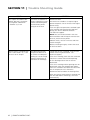
Section 11
Trouble Shooting Guide ...................................................... 41
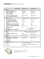
Section 12
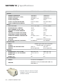
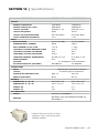
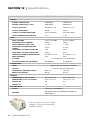
Specifications ...................................................................... 43
Section 13
Warranty .......................................................................... 47
2 | SAMLEX AMERICA INC.
Section 1 | Safety Instructions
The following safety symbols will be used in this manual to highlight safety
and information:
WARNING!
Indicates possibility of physical harm to the user in case of non-compliance.
!
CAUTION!
Indicates possibility of damage to the equipment in case of non-compliance.
i
INFO
Indicates useful supplemental information.
Please read these instructions before installing or operating the unit to prevent personal
injury or damage to the unit.
SAFETY INSTRUCTIONS - GENERAL
Installation and wiring compliance
• Installation and wiring must comply with the Local and National Electrical Codes and
must be done by a certified electrician.
Preventing electrical shock
• Always connect the grounding connection on the unit to the appropriate grounding
system.
• Disassembly / repair should be carried out by qualified personnel only.
• Disconnect all AC and DC side connections before working on any circuits associated
with the unit. Turning the on/off switch on the unit to off position may not entirely
remove dangerous voltages.
• Be careful when touching bare terminals of capacitors. The capacitors may retain high
lethal voltages even after the power has been removed. Discharge the capacitors
before working on the circuits.
Installation environment
• The inverter should be installed indoor only in a well ventilated, cool, dry
environment
• Do not expose to moisture, rain, snow or liquids of any type.
• To reduce the risk of overheating and fire, do not obstruct the suction and discharge
openings of the cooling fans.
• To ensure proper ventilation, do not install in a low clearance compartment.
SAMLEX AMERICA INC. | 3
Section 1 | Safety Instructions
Preventing fire and explosion hazards
• Working with the unit may produce arcs or sparks. Thus, the unit should not be used
in areas where there are flammable materials or gases requiring ignition protected
equipment. These areas may include spaces containing gasoline-powered machinery,
fuel tanks, and battery compartments.
Precautions when working with batteries
• Batteries contain very corrosive diluted sulphuric acid as electrolyte. Precautions
should be taken to prevent contact with skin, eyes or clothing.
• Batteries generate Hydrogen and Oxygen during charging resulting in evolution of
explosive gas mixture. Care should be taken to ventilate the battery area and follow
the battery manufacturer’s recommendations.
• Never smoke or allow a spark or flame near the batteries.
• Use caution to reduce the risk of dropping a metal tool on the battery. It could spark
or short circuit the battery or other electrical parts and could cause an explosion.
• Remove metal items like rings, bracelets and watches when working with batteries.
The batteries can produce a short circuit current high enough to weld a ring or the
like to metal and thus cause a severe burn.
• If you need to remove a battery, always remove the ground terminal from the battery
first. Make sure that all the accessories are off so that you do not cause a spark.
SAFETY INSTRUCTIONS - INVERTER RELATED
Preventing Paralleling of the AC Output
The AC output of the unit should never be connected directly to an Electrical Breaker
Panel / Load Centre which is also fed from the utility power / generator. Such a direct
connection may result in parallel operation of the different power sources and AC
power from the utility / generator will be fed back into the unit which will instantly
damage the output section of the unit and may also pose a fire and safety hazard. If an
Electrical Breaker Panel / Load Center is fed from this unit and this panel is also required
to be fed from additional alternate AC sources, the AC power from all the AC sources
(like the utility / generator / this unit) should first be fed to an Automatic / Manual Selector Switch and the output of the Selector Switch should be connected to the Electrical
Breaker Panel / Load Center.
!
CAUTION!
To prevent possibility of paralleling and severe damage to the unit, never use a
simple jumper cable with a male plug on both ends to connect the AC output
of the unit to a handy wall receptacle in the home / RV.
Preventing DC Input Over Voltage
It is to be ensured that the DC input voltage of this unit does not exceed 16.5 VDC for
4 | SAMLEX AMERICA INC.
Section 1 | Safety Instructions
the 12V battery version and 33.0 VDC for the 24V battery version to prevent permanent
damage to the unit. Please observe the following precautions:
• Ensure that the maximum charging voltage of the external battery charger / alternator / solar charge controller does not exceed 16.5 VDC for the 12V battery version and
33.0 VDC for the 24V battery version
• Do not use unregulated solar panels to charge the battery connected to this unit.
Under cold ambient temperatures, the output of the solar panel may reach > 22 VDC
for 12V Battery System and > 44 VDC for the 24V Battery system. Always use a charge
controller between the solar panel and the battery.
• Do not connect this unit to a battery system with a voltage higher than the rated battery input voltage of the unit (e.g. do not connect the 12V version of the unit to 24V
battery system or the 24V version to the 48V Battery System)
Preventing Reverse Polarity on the Input Side
When making battery connections on the input side, make sure that the polarity of battery connections is correct (Connect the Positive of the battery to the Positive terminal
of the unit and the Negative of the battery to the Negative terminal of the unit). If the
input is connected in reverse polarity, DC fuse(s) inside the inverter will blow and may
also cause permanent damage to the inverter.
!
CAUTION!
Damage caused by reverse polarity is not covered by warranty.
SAMLEX AMERICA INC. | 5
SECTION 2 | General Information
The following definitions are used in this manual for explaining various electrical
concepts, specifications and operations:
Peak Value: It is the maximum value of electrical parameter like voltage / current.
RMS (Root Mean Square) Value: It is a statistical average value of a quantity that varies
in value with respect to time. For example, a pure sine wave that alternates between
peak values of Positive 325V and Negative 325V has an RMS value of 230 VAC. Also, for
a pure sine wave, the RMS value = Peak value ÷ 1.414.
Voltage (V), Volts: It is denoted by “V” and the unit is “Volts”. It is the electrical force
that drives electrical current (I) when connected to a load. It can be DC (Direct Current
– flow in one direction only) or AC (Alternating Current – direction of flow changes periodically). The AC value shown in the specifications is the RMS (Root Mean Square) value.
Current (I), Amps, A: It is denoted by “I” and the unit is Amperes – shown as “A”. It is
the flow of electrons through a conductor when a voltage (V) is applied across it.
Frequency (F), Hz: It is a measure of the number of occurrences of a repeating event per
unit time. For example, cycles per second (or Hertz) in a sinusoidal voltage.
Efficiency, (η): This is the ratio of Power Output ÷ Power Input.
Phase Angle, (φ): It is denoted by “φ” and specifies the angle in degrees by which the
current vector leads or lags the voltage vector in a sinusoidal voltage. In a purely inductive load, the current vector lags the voltage vector by Phase Angle (φ) = 90°. In a purely
capacitive load, the current vector leads the voltage vector by Phase Angle, (φ) = 90°. In
a purely resistive load, the current vector is in phase with the voltage vector and hence,
the Phase Angle, (φ) = 0°. In a load consisting of a combination of resistances, inductances and capacitances, the Phase Angle (φ) of the net current vector will be > 0° < 90°
and may lag or lead the voltage vector.
Resistance (R), Ω: It is the property of a conductor that opposes the flow of current
when a voltage is applied across it. In a resistance, the current is in phase with the voltage. It is denoted by "R" and its unit is "Ohm" - also denoted as "Ω".
Inductive Reactance (XL), Capacitive Reactance (XC) and Reactance (X): Reactance is the
opposition of a circuit element to a change of electric current or voltage due to that
element's inductance or capacitance. Inductive Reactance (XL) is the property of a coil
of wire in resisting any change of electric current through the coil. It is proportional to
frequency and inductance and causes the current vector to lag the voltage vector by
Phase Angle (φ) = 90°. Capacitive reactance (XC) is the property of capacitive elements to
oppose changes in voltage. XC is inversely proportional to the frequency and capacitance
and causes the current vector to lead the voltage vector by Phase Angle (φ) = 90°. The
unit of both XL and XC is "Ohm" - also denoted as "Ω". The effects of inductive reactance XL to cause the current to lag the voltage by 90° and that of the capacitive
reactance XC to cause the current to lead the voltage by 90° are exactly opposite and
6 | SAMLEX AMERICA INC.
SECTION 2 | General Information
the net effect is a tendency to cancel each other. Hence, in a circuit containing both
inductances and capacitances, the net Reactance (X) will be equal to the difference between the values of the inductive and capacitive reactances. The net Reactance (X) will
be inductive if XL > XC and capacitive if XC > XL.
Impedance, Z: It is the vectorial sum of Resistance and Reactance vectors in a circuit.
Active Power (P), Watts: It is denoted as “P” and the unit is “Watt”. It is the power that
is consumed in the resistive elements of the load. A load will require additional Reactive
Power for powering the inductive and capacitive elements. The effective power required
would be the Apparent Power that is a vectorial sum of the Active and Reactive Powers.
Reactive Power (Q), VAR: Is denoted as “Q” and the unit is VAR. Over a cycle, this power
is alternatively stored and returned by the inductive and capacitive elements of the load.
It is not consumed by the inductive and capacitive elements in the load but a certain
value travels from the AC source to these elements in the (+) half cycle of the sinusoidal
voltage (Positive value) and the same value is returned back to the AC source in the (-)
half cycle of the sinusoidal voltage (Negative value). Hence, when averaged over a span
of one cycle, the net value of this power is 0. However, on an instantaneous basis, this
power has to be provided by the AC source. Hence, the inverter, AC wiring and over current protection devices have to be sized based on the combined effect of the Active and
Reactive Powers that is called the Apparent Power.
Apparent (S) Power, VA: This power, denoted by "S", is the vectorial sum of the Active
Power in Watts and the Reactive Power in “VAR”. In magnitude, it is equal to the RMS
value of voltage “V” X the RMS value of current “A”. The Unit is VA. Please note that
Apparent Power VA is more than the Active Power in Watts. Hence, the inverter, AC wiring and over current protection devices have to be sized based on the Apparent Power.
Power Factor, (PF): It is denoted by “PF” and is equal to the ratio of the Active Power
(P) in Watts to the Apparent Power (S) in VA. The maximum value is 1 for resistive types
of loads where the Active Power (P) in Watts = the Apparent Power (S) in VA. It is 0 for
purely inductive or purely capacitive loads. Practically, the loads will be a combination of
resistive, inductive and capacitive elements and hence, its value will be > 0 <1. Normally
it ranges from 0.5 to 0.8.
Load: Electrical appliance or device to which an electrical voltage is fed.
Linear Load: A load that draws sinusoidal current when a sinusoidal voltage is fed to it.
Examples are, incandescent lamp, heater, electric motor, etc.
Non-Linear Load: A load that does not draw a sinusoidal current when a sinusoidal voltage is fed to it. For example non-power factor corrected Switched Mode Power Supplies
(SMPS) used in computers, audio video equipment, battery chargers, etc.
Resistive Load: A device or appliance that consists of pure resistance (like filament
lamps, cook tops, toaster, coffee maker etc.) and draws only Active Power (Watts) from
SAMLEX AMERICA INC. | 7
SECTION 2 | General Information
the inverter. The inverter can be sized based on the Active Power rating (Watts) without
creating overload.
Reactive Load: A device or appliance that consists of a combination of resistive, inductive and capacitive elements (like motor driven tools, refrigeration compressors, microwaves, computers, audio/ video etc.). These devices require Apparent Power (VA) from
the inverter to operate. The Apparent Power is a vectorial sum of Active Power (Watts)
and Reactive Power (VAR). The inverter has to be sized based on the higher Apparent
Power (VA).
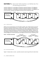
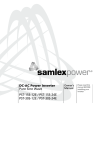
Output Voltage Waveforms
360
320
280
240
200
160
120
80
40
0
40
80
120
160
200
240
280
320
360
Modified Sine
Wave sits at
ZERO for some
time and then
rises or falls
Sine Wave
Modified Sine Wave
Pure Sine Wave
crosses 0.0V
instantaneously
TIME
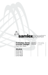
Fig. 2.1: Pure and Modified Sine Waveforms
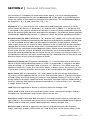
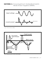
The output waveform of the Samlex PST Series inverters is a pure sine wave like the
waveform of the grid power. Please see sine wave represented in the Fig. 2.1 that also
shows modified waveform for comparison.
In a sine wave, the voltage rises and falls smoothly with a smoothly changing phase
angle and also changes its polarity instantly when it crosses 0 Volts. In a modified sine
wave, the voltage rises and falls abruptly, the phase angle also changes abruptly and
it sits at 0Vs for some time before changing its polarity. Thus, any device that uses a
control circuitry that senses the phase (for voltage / speed control) or instantaneous zero
voltage crossing (for timing control) will not work properly from a voltage that has a
modified sine waveform.
Also, as the modified sine wave is a form of square wave, it is comprised of multiple
sine waves of odd harmonics (multiples) of the fundamental frequency of the modified
sine wave. For example, a 50 Hz modified sine wave will consist of sine waves with odd
harmonic frequencies of 3rd (150 Hz), 5th (250 Hz), 7th (350 Hz) and so on. The high
8 | SAMLEX AMERICA INC.
SECTION 2 | General Information
frequency harmonic content in a modified sine wave produces enhanced radio interference, higher heating effect in inductive loads like microwaves and motor driven devices
like hand tools, refrigeration / air-conditioning compressors, pumps etc. The higher
frequency harmonics also produce overloading effect in low frequency capacitors due to
lowering of their capacitive reactance by the higher harmonic frequencies. These capacitors are used in ballasts for fluorescent lighting for Power Factor improvement and in
single-phase induction motors as start and run capacitors. Thus, modified and square
wave inverters may shut down due to overload when powering these devices.
Advantages of Pure Sine Wave Inverters
• The output waveform is a sine wave with very low harmonic distortion and cleaner
power like utility supplied electricity.
• Inductive loads like microwaves, motors, transformers etc. run faster, quieter
and cooler.
• More suitable for powering fluorescent lighting fixtures containing power factor
improvement capacitors and single phase motors containing start and run capacitors
• Reduces audible and electrical noise in fans, fluorescent lights, audio amplifiers, TV,
fax and answering machines.
• Does not contribute to the possibility of crashes in computers, weird print outs and
glitches in monitors
Some examples of devices that may not work properly with modified sine
wave and may also get damaged are given below:
• Laser printers, photocopiers, and magneto-optical hard drives.
• Built-in clocks in devices such as clock radios, alarm clocks, coffee makers, bread-makers, VCR, microwave ovens etc. may not keep time correctly.
• Output voltage control devices like dimmers, ceiling fan / motor speed control may
not work properly (dimming / speed control may not function).
• Sewing machines with speed / microprocessor control.
• Transformer-less capacitive input powered devices like (i) Razors, flashlights, nightlights, smoke detectors etc. (ii) Re-chargers for battery packs used in hand power
tools. These may get damaged. Please check with the manufacturer of these types of
devices for suitability.
• Devices that use radio frequency signals carried by the AC distribution wiring.
• Some new furnaces with microprocessor control / Oil burner primary controls.
• High intensity discharge (HID) lamps like Metal Halide lamps. These may get damaged.
Please check with the manufacturer of these types of devices for suitability.
• Some fluorescent lamps / light fixtures that have power factor correction capacitors.
The inverter may shut down indicating overload.
SAMLEX AMERICA INC. | 9
SECTION 2 | General Information
Power Rating of the Inverters
The continuous output power rating of the inverter is specified in Active Power in Watts
for resistive types of loads like heating elements, incandescent lamps etc. where Power
Factor (PF) = 1. The Surge Power rating is for < 1 sec.
Non resistive / reactive loads with Power Factor < 1 like motors (PF = 0.4 to 0.8), non
Power Factor corrected electronics (PF = 0.5 to 0.6) etc, will draw higher Apparent Power
in Volt Amps (VA). This Apparent Power is the sum of Active Power in Watts plus Reactive Power in VAR and is = Active Power in Watts ÷ Power Factor. Thus, for such reactive
loads, higher sized inverter is required based on the Apparent Power. Further, all reactive types of loads require higher inrush / starting surge power that may last for
> 1 to 5 sec and subsequent lower running power. If the inverter is not sized adequately
based on the type of AC load, it is likely to shut down or fail prematurely due to
repeated overloading.
i
INFO
The manufacturers’ specification for power rating of the appliances and devices
indicates only the running power required. The surge power required by some
specific types of devices as explained above has to be determined by actual testing or by checking with the manufacturer. This may not be possible in all cases
and hence, can be guessed at best, based on some general rules of thumb.
Table 2.1 below lists some common loads that require high surge power on start up. A
“Sizing Factor” has been recommended against each which is a multiplication factor
to be applied to the rated running Watt rating of the load to arrive at the Continuous
Power Rating of the inverter (Multiply the running Watts of the device/ appliance by the
Sizing Factor to arrive at the size of the inverter).
TABLE 2.1: INVERTER SIZING FACTOR
Type of Device or Appliance
Inverter
Sizing Factor*
Air Conditioner / Refrigerator / Freezer (Compressor based)
5
Air Compressor
4
Sump Pump / Well Pump / Submersible Pump
3
Dishwasher / Clothes Washer
3
Microwave (where rated output power is the cooking power)
2
Furnace Fan
3
Industrial Motor
3
Portable Kerosene / Diesel Fuel Heater
3
Circular Saw / Bench Grinder
3
Incandescent / Halogen / Quartz Lamps
3
Table Continues Next Page ►
10 | SAMLEX AMERICA INC.
SECTION 2 | General Information
TABLE 2.1: INVERTER SIZING FACTOR
Type of Device or Appliance
Inverter
Sizing Factor*
Laser Printer / Other Devices using Quartz Lamps for heating
4
Switch Mode Power Supplies (SMPS): no Power Factor correction
3
Photographic Strobe / Flash Lights
4 (Note 1)
* Multiply the Running Active Power Rating {Watts} of the appliance by this Factor to arrive at
the Continuous Power Rating of the inverter for powering this appliance.
TABLE 2.1: NOTES 1.For photographic strobe / flash unit, the surge power of the inverter should be > 4
times the Watt Sec rating of photographic strobe / flash unit.
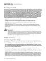
SECTION 3 | Limiting Electro-Magnetic
Interference (EMI)
These inverters contain internal switching devices that generate conducted and radiated
electromagnetic interference (EMI). The EMI is unintentional and cannot be entirely
eliminated. The magnitude of EMI is, however, limited by circuit design to acceptable
levels as per limits laid down in European Standard EN55022: Class B and EN55024.
These limits are designed to provide reasonable protection against harmful interference when the equipment is operated in a residential environment. These inverters can
conduct and radiate radio frequency energy and, if not installed and used in accordance
with the instruction manual, may cause harmful interference to radio communications.
The effects of EMI will also depend upon a number of factors external to the inverter
like proximity of the inverter to the EMI receptors, types and quality of connecting wires
and cables etc. EMI due to factors external to the inverter may be reduced as follows:
i
INFO
- Ensure that the inverter is firmly grounded to the ground system
of the building or the vehicle
- Locate the inverter as far away from the EMI receptors like radio, audio
and video devices as possible
- Keep the DC side cables between the battery and the inverter
as short as possible.
- Twist the DC side cables. This will partially cancel out the radiated noise
from the cables
-Shield the DC side cables with metal sheathing / copper foil / braiding:
- Use coaxial shielded cable for all antenna inputs (instead of 300 ohm twin leads)
- Use high quality shielded cables to attach audio and video devices to one another
- Limit operation of other high power loads when operating audio /
video equipment
SAMLEX AMERICA INC. | 11
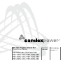
SECTION 4 | Powering Direct / Embedded Switch
Mode Power Supplies (SMPS)
Switch Mode Power Supplies (SMPS) are extensively used to convert the incoming AC
power into various voltages like 3.3V, 5V, 12V, 24V etc. that are used to power various
devices and circuits used in electronic equipment like battery chargers, computers, audio
and video devices, radios etc. These power supplies use large capacitors in their input
section for filtration. When the power supply is first turned on, there is a very large
inrush current drawn by the power supply as the input capacitors are charged (The capacitors act almost like a short circuit at the instant the power is turned on). The inrush
current at turn-on is several to tens of times larger than the rated RMS input current
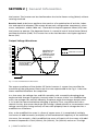
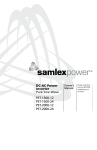
and lasts for a few milliseconds. An example of the input voltage versus input current
waveforms is given in Fig. 4.1. It will be seen that the initial input current pulse just after
turn-on is > 15 times larger than the steady state RMS current. The inrush dissipates in
around 2 or 3 cycles i.e. in around 40 to 60 milliseconds for 50 Hz sine wave.
Further, due to the presence of high value of input filter capacitors, the current drawn
by an SMPS (With no Power Factor correction) is not sinusoidal but non-linear as shown
in Fig 4.2 above. The steady state input current of SMPS is a train of non-linear pulses
instead of a sinusoidal wave. These pulses are two to four milliseconds duration each
when on 50 Hz power, with a very high Crest Factor corresponding to peak values
around three times the RMS value of the input current:
(Crest Factor = Peak value ÷ RMS value).
Many SMPS units incorporate “Inrush Current Limiting”. The most common method is
the NTC (Negative Temperature Coefficient) resistor. The NTC resistor has a high resistance when cold and a low resistance when hot. The NTC resistor is placed in series with
the input to the power supply. The cold resistance limits the input current as the input
capacitors charge up. The input current heats up the NTC and the resistance drops
during normal operation. However, if the power supply is quickly turned off and back
on, the NTC resistor will be hot so its low resistance state will not prevent an inrush
current event.
The inverter should, therefore, be sized adequately to withstand the high inrush current
and the high Crest Factor of the current drawn by the SMPS. Hence, it is recommended
that for purposes of sizing the inverter, the continuous power of the inverter should be
> 3 times the continuous rated power of the SMPS. For example, an SMPS rated at
100 Watts should be powered from an inverter that has continuous power of
> 300 Watts.
12 | SAMLEX AMERICA INC.
SECTION 4 | Powering Direct / Embedded Switch
Mode Power Supplies (SMPS)
Input voltage
RMS Current
Inrush current
Fig 4.1: Inrush current in an SMPS
Peak Current
Non-linear
Input Current
RMS Current
Input Sine
Wave Voltage
TIME
Fig. 4.2: High Crest Factor of current drawn by SMPS
SAMLEX AMERICA INC. | 13
SECTION 5 | Principle of Operation
These inverters convert DC battery voltage to AC voltage with an RMS (Root Mean
Square) value of 230 VAC, 50 Hz RMS.
The waveform of the AC voltage is a pure sine wave form that is same as the waveform
of grid power (Supplementary information on pure sine waveform and its advantages
are discussed on pages 8 & 9).
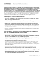
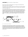
Fig. 5.1 below specifies the characteristics of 230 VAC, 50 Hz pure sine waveform. The
instantaneous value and polarity of the voltage varies cyclically with respect to time. For
example, in one cycle in a 230 VAC, 50 Hz system, it slowly rises in the positive direction
from 0V to a peak positive value “Vpeak” = + 325V, slowly drops to 0V, changes the
polarity to negative direction and slowly increases in the negative direction to a peak
negative value “Vpeak” = - 325V and then slowly drops back to 0V. There are 50 such
cycles in 1 sec. Cycles per second is called the “Frequency” and is also termed “Hertz
(Hz)”.
+VPEAK = + 325V
VRMS = 230 VAC
+
OV
-
TIME
-VPEAK = -325V
Fig. 5.1: 230 VAC, 50 Hz Pure Sine Waveform
The voltage conversion takes place in two stages. In the first stage, the DC voltage
of the battery is converted to a high voltage DC using high frequency switching and
Pulse Width Modulation (PWM) technique. In the second stage, the high voltage DC is
converted to 230 VAC, 50 Hz sine wave AC again using PWM technique. This is done by
using a special wave shaping technique where the high voltage DC is switched at a high
frequency and the pulse width of this switching is modulated with respect to a reference sine wave.
14 | SAMLEX AMERICA INC.
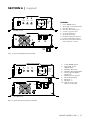
SECTION 6 | Layout
600W Power Inverter
1
ON
2
3
4
POWER
OVER
OVER
LOAD
TEMP
OFF
5
OUTPUT
230 VAC
50HZ
600W
PST-60S: Front
6
7
NEG -
8
PST-60S: Back
LEGEND
1.
2.
Power ON/OFF Switch
Green LED - Power Ouptut Status
3.
4.
Red LED - Overload
Red LED - Over temperature
5.
6.
7.
“Schuko” type AC outlet
Cooling Fan Opening
Grounding Terminal
8. Negative (-) DC Input Terminal
9. Positive (+) DC Input Terminal
10. Modular Jack for RC-15 Remote
Control (Bottom of Unit)
POS +
9
10
Fig. 6.1: Layout of PST-60S-12E, PST--60S-24E
1000W POWER INVERTER
PST-60S-230-Layout
2
3
4
POWER
OVER
OVER
LOAD
TEMP
ON
1
OUTPUT
230VAC
50Hz
1000w
OFF
5
PST-100S: Front
6
9
NEG -
Power ON/OFF Switch
Green LED - Power
Output Status
3.
4.
Red LED - Over load
Red LED - Over Temperature
5.
Schuko Type AC Output
Receptacle
Opening for Cooling Fan
Grounding Terminal
DC Input “-”
DC Input “+”
Remote Control Jack
(Bottom of the unit)
6.
7.
8.
9.
10.
10
8
1.
2.
POS +
7
PST-100S: Back
Fig. 6.2: Layout of PST-100S-12E, PST--100S-24E
SAMLEX AMERICA INC. | 15
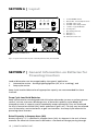
SECTION 6 | Layout
2
TEMP
LOAD
ON
I
OUTPUT
230V
50Hz
3
OVER POWER
O
4
OVER
1
OFF
10
6
Pure Sine Wave Inverter
Remote
PST-150S, PST-200S: Front
9
6
1.
2.
3.
4.
5.
6.
7.
8.
9.
10.
Power ON/OFF Switch
Green LED - Power Output Status
Red LED - Over Load
Red LED - Over Temperature
“Schuko” Type AC Outlets
Cooling Fans
Grounding Terminal
DC Input “-”
DC Input “+”
Remote Control Jack
8
POS +
NEG -
6
7
PST-150S, PST-200S: Back
Fig. 6.3: Layout of PST-150S-12E, PST--150S-24E, PST-200S-12E, PST--200S-24E
PST-150S-230 & PST-200S-230: Layout
SECTION 7 | General Information on Batteries for
Powering Inverters
Lead-acid batteries can be categorized by the type of application:
1. Automotive service - Starting/Lighting/Ignition (SLI, a.k.a. cranking), and
2. Deep cycle service.
Deep Cycle Lead Acid Batteries of appropriate capacity are recommended for these
inverters.
Deep Cycle Lead Acid Batteries
Deep cycle batteries are designed with thick-plate electrodes to serve as primary power
sources, to have a constant discharge rate, to have the capability to be deeply discharged up to 80 % capacity and to repeatedly accept recharging. They are marketed
for use in recreation vehicles (RV), boats and electric golf carts – so they may be referred
to as RV batteries, marine batteries or golf cart batteries. Use Deep Cycle batteries for
powering these inverters.
Rated Capacity in Ampere-hour (Ah)
Battery capacity “C” is specified in Ampere-hours (Ah). An Ampere is the unit of measurement for electrical current and is defined as a Coulomb of charge passing through
16 | SAMLEX AMERICA INC.
SECTION 7 | General Information on Batteries for
Powering Inverters
an electrical conductor in one second. The Capacity “C” in Ah relates to the ability of the
battery to provide a constant specified value of discharge current (also called “C-Rate”) over
a specified time in hours before the battery reaches a specified discharged terminal voltage
(Also called “End Point Voltage”) at a specified temperature of the electrolyte. As a benchmark, the automotive battery industry rates batteries at a “Discharge Rate” C/20 Amperes
corresponding to 20 Hour discharge period. The rated capacity “C” in Ah in this case will be
the number of Amperes of current the battery can deliver for 20 Hours at 80ºF (26.7ºC) till
the voltage drops to 1.75V / Cell i.e. 10.5V for 12V battery, 21V for 24V battery and 42V for a
48V battery. For example, a 100 Ah battery will deliver 5A for 20 Hours.
Rated Capacity in Reserve Capacity (RC)
Battery capacity may also be expressed as Reserve Capacity (RC) in minutes typically for
automotive SLI (Starting, Lighting and Ignition) batteries. It is the time in minutes a
vehicle can be driven after the charging system fails. This is roughly equivalent to the
conditions after the alternator fails while the vehicle is being driven at night with the
headlights on. The battery alone must supply current to the headlights and the computer/ignition system. The assumed battery load is a constant discharge current of 25 A.
Reserve capacity is the time in minutes for which the battery can deliver 25 Amperes at
80ºF (26.7ºC) till the voltage drops to 1.75V / Cell i.e. 10.5V for 12V battery, 21V for 24V
battery and 42V for 48V battery. Approximate relationship between the two units is:
Capacity “C” in Ah = Reserve Capacity in RC minutes x 0.6
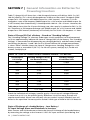
Typical Battery Sizes
The Table 7.1 below shows details of some popular battery sizes: Table 7.1: Popular Battery Sizes
BCI* Group
Battery Voltage, V
Battery Capacity, Ah
27 / 31
12
105
4D
12
160
8D
12
225
GC2**
6
220
* Battery Council International; ** Golf Cart
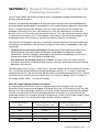
Specifying Charging / Discharging Currents: C-Rate
Electrical energy is stored in a cell / battery in the form of DC power. The value of the
stored energy is related to the amount of the active materials pasted on the battery
plates, the surface area of the plates and the amount of electrolyte covering the plates.
As explained above, the amount of stored electrical energy is also called the Capacity of
the battery and is designated by the symbol “C”. The time in Hours over which the battery is discharged to the “End Point Voltage” for
purposes of specifying Ah capacity depends upon the type of application. Let us denote
this discharge time in hours by “T”. Let us denote the discharge current of the battery
SAMLEX AMERICA INC. | 17
SECTION 7 | General Information on Batteries for
Powering Inverters
as the “C-Rate”. If the battery delivers a very high discharge current, the battery will be
discharged to the “End Point Voltage” in a shorter period of time. On the other hand,
if the battery delivers a lower discharge current, the battery will be discharged to the
“End Point Voltage” after a longer period of time. Mathematically:
EQUATION 1:
Discharge current “C-Rate” = Capacity “C” in Ah ÷ Discharge Time “T”
Table 7.2 below gives some examples of C-Rate specifications and applications:
Table 7.2: Discharge current rates - “C-Rates”
Hours of discharge time
“T” till the “End Point
Voltage”
C-Rate Discharge Current in Amps
Fraction
Decimal
Subscript
Example of C-Rate
Discharge Currents for
100 Ah battery
0.5 Hrs.
2C
2C
2C
200A
1 Hrs.
1C
1C
1C
100A
5 Hrs.
C/5
0.2C
C5
20A
8 Hrs.
(UPS application)
C/8
0.125C
C8
12.5A
10 Hrs.
(Telecom application)
C/10
0.1C
C10
10A
20 Hrs.
(Automotive application)
C/20
0.05C
C20
5A
100 Hrs.
C/100
0.01C
C100
1A
NOTE: When a battery is discharged over a shorter time, its specified “C-Rate” discharge current
will be higher. For example, the “C-Rate” discharge current at 5 Hour discharge period i.e. 0.2C
/ C5 / C/5 Amps will be 4 times higher than the “C-Rate” discharge current at 20 Hour discharge
period i.e. 0.05C / C20 / C/20 Amps.
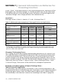
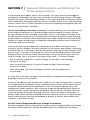
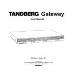
Charging / Discharging Curves
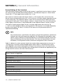
Fig. 7.1 (page 19) shows the charging and discharging characteristics of a typical, 6 cell,
12V, Lead Acid battery at electrolyte temperature of 80°F (by convention, battery data
is normally presented at 80°F). The curves show the % State of Charge (X-axis) versus
terminal voltage (Y-axis) during charging and discharging at different C-Rates. For 24V
battery, multiply voltage on Y-axis by 2 for 48V battery, multiply voltage on Y-axis by 4
(Please note that X-axis shows % State of charge. State of Discharge will be = 100% % State of Charge). These curves will be referred to in subsequent explanations.
Reduction in Usable Capacity at Higher Discharge Rates –
Typical in Inverter Application
As stated above, the rated capacity of the battery in AH is normally applicable at a discharge rate of 20 Hours. As the discharge rate is increased as in cases where the inverters
are driving higher capacity loads, the usable capacity reduces due to “Peukert Effect”.
This relationship is not linear but is more or less according to the Table 7.3 (page 19).
18 | SAMLEX AMERICA INC.
SECTION 7 | General Information on Batteries for
Powering Inverters
12 Volt Lead-Acid Battery Chart - 80˚F
16.5
C/5
C/10
16.0
CHARGE
C/20
15.5
C/40
15.0
Battery Voltage in VDC
14.5
14.0
13.5
13.0
C/100
C/20
C/10
12.5
C/5
12.0
DISCHARGE
C/3
11.5
11.0
10.5
Please note that X-axis shows %
State of Charge. State of Discharge
will be = 100% - % State of Charge.
10.0
9.5
9.0
0
10
20
30
40
50
60
70
80
90
100
110
120
130
Battery State of Charge in Percent (%)
Fig. 7.1: Charging / Discharging Curves for 12 V Lead Acid Battery
Table 7.3 Battery Capacity versus Rate of Discharge – C-Rate
C-Rate Discharge Current
Usable Capacity (%)
C/20
100%
C/10
87%
C/8
83%
C/6
75%
C/5
70%
C/3
60%
C/2
50%
1C
40%
SAMLEX AMERICA INC. | 19
SECTION 7 | General Information on Batteries for
Powering Inverters
Table 7.3 (page 19) will show that a 100 Ah capacity battery will deliver 100% (i.e. full
100 Ah) capacity if it is slowly discharged over 20 hours at the rate of 5 Amperes (50W
output for a 12V inverter and 100W output for a 24V inverter). However, if it is discharged at a rate of 50 Amperes (500W output for a 12V inverter and 1000W output for
a 24V inverter) then theoretically, it should provide 100 AH ÷ 50 = 2 hours. However, the
Table above shows that for 2 hours discharge rate, the capacity is reduced to 50% i.e. 50
Ah. Therefore, at 50 Ampere discharge rate (500W output for a 12V inverter and 1000W
output for a 24V inverter) the battery will actually last for 50 Ah ÷ 50 Amperes = 1 Hour.
State of Charge (SOC) of a Battery – Based on “Standing Voltage”
The “Standing Voltage” of a battery under open circuit conditions (no load connected
to it) can approximately indicate the State of Charge (SOC) of the battery. The “Standing
Voltage” is measured after disconnecting any charging device(s) and the battery load(s)
and letting the battery “stand” idle for 3 to 8 hours before the voltage measurement
is taken. Table 7.4 below shows the State of Charge versus Standing Voltage for a 12V
battery system at around 80°F (26.7ºC). For 24-volt systems, multiply by 2; for 48-volt
systems, multiply by 4.
Table 7.4: State of Charge versus Standing Voltage – 12V Battery
Percentage of
Full Charge
Standing Voltage of 6 Cell,
12V Nominal Battery
Standing Voltage
of Individual Cells
100%
12.63V
2.105V
90%
12.6V
2.10V
80%
12.5V
2.08V
70%
12.3V
2.05V
60%
12.2V
2.03V
50%
12.1V
2.02V
40%
12.0V
2.00V
30%
11.8V
1.97V
20%
11.7V
1.95V
10%
11.6V
1.93V
0%
= / < 11.6V
= / < 1.93V
Check the individual cell voltages / specific gravity. If the inter cell voltage difference
is more than a 0.2 V, or the specific gravity difference is 0.015 or more, the cells will
require equalization. Please note that only the non-sealed / vented / flooded / wet cell
batteries are equalized. Do not equalize sealed / VRLA type of AGM or Gel Cell Batteries.
State of Discharge of a loaded battery – Low Battery /
DC Input Voltage Alarm and Shutdown in Inverters
Most inverter and UPS hardware estimate the State of Discharge of the loaded battery
by measuring the voltage at the inverter’s / UPS’s DC input terminals (considering that
20 | SAMLEX AMERICA INC.
SECTION 7 | General Information on Batteries for
Powering Inverters
the DC input cables are thick enough to allow a negligible voltage drop between the
battery and the inverter) .
Inverters are normally provided with a buzzer alarm to warn that the loaded battery
has been deeply discharged to around 80% of the rated capacity. Normally, the buzzer
alarm is triggered when the voltage at the DC input terminals of the inverter has
dropped to around 10.7V for a 12V battery or 21.4V for 24V battery at C-Rate discharge current of C/5 Amps and electrolyte temp. of 78°C (by convention, battery data
is normally presented at 78°C). The inverter is shut down if the terminal voltage at C/5
discharge current falls further to 10V for 12V battery (20V for 24V battery).
The State of Discharge of a battery is normally estimated based on the measured terminal voltage of the battery. The terminal voltage of the battery is dependent upon the
following:
- Temperature of the battery electrolyte: Temperature of the electrolyte affects the
electrochemical reactions inside the battery and produces a Negative Voltage
Coefficient – during charging / discharging, the terminal voltage drops with rise in
temperature and rises with drop in temperature
- The amount of discharging current or “C-Rate”: A battery has non linear internal
resistance and hence, as the discharge current increases, the battery terminal voltage
decreases non-linearly
The discharge curves at Fig. 7.1 show the % State of Charge versus the terminal voltage
of a 12V battery under different charge /discharge currents, i.e. “C-Rates” and fixed
temperature of 78°F. (By convention, battery data is normally presented at 78°F). (Please
note that the X-Axis of the curves shows the % of State of Charge. The % of State of
Discharge will be 100% - % State of Charge).
Low DC Input Voltage Alarm in Inverters
As stated earlier, the buzzer alarm is triggered when the voltage at the DC input
terminals of the inverter has dropped to around 10.7V for a 12V battery (21.4V for 24V
battery) at C-Rate discharge current of C/5 Amps. Please note that the terminal voltage
relative to a particular of State Discharge decreases with the rise in the value of the
discharge current. For example, terminal voltages for a State of Discharge of 80% (State
of Charge of 20%) for various discharge currents will be as follows:
Discharge Current:
C-Rate
Terminal Voltage at 80% State
of Discharge (20% SOC)
Terminal Voltage When Completely
Discharged (0% SOC)
C/3 A
10.45V
09.50V
C/5 A
10.90V
10.30V
C/10 A
11.95V
11.00V
C/20 A
11.85V
11.50V
C/100 A
12.15V
11.75V
SAMLEX AMERICA INC. | 21
SECTION 7 | General Information on Batteries for
Powering Inverters
In the example given above, the 10.7V Low Battery / DC Input Alarm would trigger at
around 80% discharged state (20% SOC) when the C-Rate discharge current is C/5 Amps.
However, for lower C-Rate discharge current of C/10 Amps and lower, the battery will be
almost completely discharged when the alarm is sounded. Hence, if the C-Rate discharge
current is lower than C/5 Amps, the battery may have completely discharged by the time
the Low DC Input Alarm is sounded. Low DC Input Voltage Shut-down in Inverters: As explained above, at around 80% State
of Discharge of the battery at C-Rate discharge current of around C/5 Amps, the Low
DC Input Voltage Alarm is sounded at around 10.7V for a 12V battery (at around 21.4V
for 24V battery) to warn the user to disconnect the battery to prevent further draining
of the battery. If the load is not disconnected at this stage, the batteries will be drained
further to a lower voltage and to a completely discharged condition that is harmful for
the battery and for the inverter.
Inverters are normally provided with a protection to shut down the output of the
inverter if the DC voltage at the input terminals of the inverter drops below a threshold
of around 10V for a 12V battery (20V for 24V battery). Referring to the Discharge Curves
given at Fig 7.1, the State of Discharge for various C-Rate discharge currents for battery
voltage of 10V is as follows: (Please note that the X-Axis of the curves shows the % of
State of Charge. The % of State of Discharge will be 100% - % State of Charge):
- 85% State of Discharge (15% State of Charge) at very high C-rate discharge
current of C/3 Amps.
- 100% State of Discharge (0 % State of Charge) at high C-Rate discharge
current of C/5 Amps.
- 100% discharged (0% State of charge) at lower C-rate Discharge current
of C/10 Amps.
It is seen that at DC input voltage of 10V, the battery is completely discharged for C-rate
discharge current of C/5 and lower.
In view of the above, it may be seen that a fixed Low DC Input Voltage Alarm is not useful. Temperature of the battery further complicates the situation. All the above analysis
is based on battery electrolyte temperature of 78°F. The battery capacity varies with
temperature. Battery capacity is also a function of age and charging history. Older batteries have lower capacity because of shedding of active materials, sulfation, corrosion,
increasing number of charge / discharge cycles etc. Hence, the State of Discharge of a
battery under load cannot be estimated accurately. However, the Low DC Input Voltage
Alarm and Shut Down function are designed to protect te inverter from excessive current draw at the lower voltage.
Use of External Programmable Low Voltage Disconnects
The above ambiguity can be removed by using an external, programmable Low Voltage
Disconnect where more exact voltage threshold can be set to disconnect the battery
22 | SAMLEX AMERICA INC.
SECTION 7 | General Information on Batteries for
Powering Inverters
based on the actual application requirements.
Please consider using the following Programmable Low Battery Cut-off / “Battery
Guard” Models manufactured by Samlex America, Inc. www.samlexamerica.com
- BG-40 (40A) – For up to 400W, 12V inverter or 800W , 24V inverter
- BG-60 (60A) - For up to 600W, 12V inverter or 1200W , 24V inverter
- BG-200 (200A) - For up to 2000W, 12V inverter or 4000W , 24V inverter
Depth of Discharge of Battery and Battery Life
The more deeply a battery is discharged on each cycle, the shorter the battery life. Using
more batteries than the minimum required will result in longer life for the battery bank.
A typical cycle life chart is given in the Table 7.5 below:
Table 7.5: Typical Cycle Life Chart
Depth of Discharge
% of Ah Capacity
Cycle Life of Group
27 /31
Cycle Life of Group
8D
Cycle Life of Group
GC2
10
1000
1500
3800
50
320
480
1100
80
200
300
675
100
150
225
550
NOTE: It is recommended that the depth of discharge should be limited to 50%.
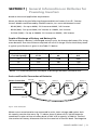
Series and Parallel Connection of Batteries
Series Connection
24V Inverter
or 24V Charger
Cable “A”
Battery 4
Battery 3
Battery 2
Battery 1
6V
6V
6V
6V
Cable “B”
Fig 7.2: Series Connection
When two or more batteries are connected in series, their voltages add up but their
Ah capacity remains the same. Fig. 7.2 above shows 4 pieces of 6V, 200 Ah batteries
connected in series to form a battery bank of 24V with a capacity of 200 Ah. The Positive terminal of Battery 4 becomes the Positive terminal of the 24V bank. The Negative
SAMLEX AMERICA INC. | 23
SECTION 7 | General Information on Batteries for
Powering Inverters
terminal of Battery 4 is connected to the Positive terminal of Battery 3. The Negative
terminal of Battery 3 is connected to the Positive terminal of Battery 2. The Negative
terminal of Battery 2 is connected to the Positive terminal of Battery 1. The Negative terminal of Battery 1 becomes the Negative terminal of the 24V battery bank.
Cable “A”
Parallel Connection
12V Inverter
or 12V Charger
Battery 1
Battery 2
Battery 3
Battery 4
12V
12V
12V
12V
Cable “B”
Fig 7.3: Parallel Connection
When two or more batteries are connected in parallel, their voltage remains the same
but their Ah capacities add up. Fig. 7.3 above shows 4 pieces of 12V, 100 Ah batteries
connected in parallel to form a battery bank of 12V with a capacity of 400 Ah. The four
Positive terminals of Batteries 1 to 4 are paralleled (connected together) and this common Positive connection becomes the Positive terminal of the 12V bank. Similarly, the
four Negative terminals of Batteries 1 to 4 are paralleled (connected together) and this
common Negative connection becomes the Negative terminal of the 12V battery bank.
12V String 1
Series – Parallel Connection
12V String 2
Battery 1
Battery 2
6V
6V
Battery 3
Battery 4
Cable “A”
12V Inverter
or 12V Charger
6V
6V
Cable “B”
Fig. 7.4: Series-Parallel Connection
Figure 7.4 above shows a series – parallel connection consisting of four 6V, 200 AH bat-
24 | SAMLEX AMERICA INC.
SECTION 7 | General Information on Batteries for
Powering Inverters
teries to form a 12V, 400 Ah battery bank. Two 6V, 200 Ah batteries, Batteries 1 and 2
are connected in series to form a 12V, 200 Ah battery (String 1). Similarly, two 6V, 200 Ah
batteries, Batteries 3 and 4 are connected in series to form a 12V, 200 Ah battery
(String 2). These two 12V, 200 Ah Strings 1 and 2 are connected in parallel to form a
12V, 400 Ah bank.
!
CAUTION!
When 2 or more batteries / battery strings are connected in parallel and are
then connected to an inverter or charger (See Figs 7.3 and 7.4 given above),
attention should be paid to the manner in which the charger / inverter is connected to the battery bank. Please ensure that if the Positive output cable of
the battery charger / inverter (Cable “A”) is connected to the Positive battery
post of the first battery (Battery 1 in Fig 7.3) or to the Positive battery post of
the first battery string (Battery 1 of String 1 in Fig. 7.4), then the Negative output cable of the battery charger / inverter (Cable “B”) should be connected to
the Negative battery post of the last battery (Battery 4 as in Fig. 7.3) or to the
Negative Post of the last battery string (Battery 4 of Battery String 2 as in
Fig. 7.4). This connection ensures the following:
- The resistances of the interconnecting cables will be balanced.
- All the individual batteries / battery strings will see the same series resistance.
- All the individual batteries will charge / discharge at the same charging
current and thus, will be charged to the same state at the same time.
- None of the batteries will see an overcharge condition.
Sizing the Inverter Battery Bank
One of the most frequently asked questions is, "how long will the batteries last?" This
question cannot be answered without knowing the size of the battery system and the
load on the inverter. Usually this question is turned around to ask “How long do you
want your load to run?”, and then specific calculation can be done to determine the
proper battery bank size.
There are a few basic formulae and estimation rules that are used:
1. Power in Watts (W) = Voltage in Volts (V) x Current in Amperes (A).
2.
For an inverter running from a 12V battery system, the DC current required from
the 12V batteries is the AC power delivered by the inverter to the load inWatts (W)
divided by 10 & for an inverter running from a 24V battery system, the DC current
required from the 24V batteries is the AC power delivered bythe inverter to the
load in Watts (W) divided by 20.
3.
Energy required from the battery = DC current to be delivered
(A) x time in Hours (H).
SAMLEX AMERICA INC. | 25
SECTION 7 | General Information on Batteries for
Powering Inverters
The first step is to estimate the total AC watts (W) of load(s) and for how long the
load(s) will operate in hours (H). The AC watts are normally indicated in the electrical
nameplate for each appliance or equipment. In case AC watts (W) are not indicated,
Formula 1 given above may be used to calculate the AC watts by multiplying 120 VAC /
230 VAC by the AC current in Amperes. The next step is to estimate the DC current in
Amperes (A) from the AC watts as per Formula 2 above. An example of this calculation
for a 12V inverter is given below:
Let us say that the total AC Watts delivered by the 12V inverter = 1000W.
Then, using Formula 2 above, the DC current to be delivered by the 12V batteries
= 1000W ÷10 = 100 Amperes.
Next, the energy required by the load in Ampere Hours (Ah) is determined.
For example, if the load is to operate for 3 hours then as per Formula 3 above, the
energy to be delivered by the 12V batteries = 100 Amperes × 3 Hours = 300 Ampere
Hours (Ah).
Now, the capacity of the batteries is determined based on the run time and
the usable capacity.
From Table 7.3 “Battery Capacity versus Rate of Discharge”, the usable capacity at 3
Hour discharge rate is 60%. Hence, the actual capacity of the 12V batteries to deliver
300 Ah will be equal to: 300 Ah ÷ 0.6 = 500 Ah.
And finally, the actual desired rated capacity of the batteries is determined based on
the fact that normally only 80% of the capacity will be available with respect to the
rated capacity due to non availability of ideal and optimum operating and charging
conditions. So the final requirements will be equal to: 500 Ah ÷ 0.8 = 625 Ah (note that
the actual energy required by the load was 300 Ah).
It will be seen from the above that the final rated capacity of the batteries is almost 2
times the energy required by the load in Ah. Thus, as a rule of thumb, the Ah capacity
of the batteries should be twice the energy required by the load in Ah.
For the above example, the 12V batteries may be selected as follows:
- Use 6 Group 27/31, 12V, 105 Ah batteries in parallel to make up 630 Ah, or
- Use 3 Group 8D, 12V, 225 Ah batteries in parallel to make up 675 Ah.
26 | SAMLEX AMERICA INC.
SECTION 8 | Installation
WARNING!
1.Before commencing installation, please read the safety instructions explained
in the Section titled “Safety Instructions” on page 3.
2.It is recommended that the installation should be undertaken by a qualified,
licensed / certified electrician.
3.Various recommendations made in this manual on installation will be superseded by the National / Local Electrical Codes related to the location of the
unit and the specific application.
Location of Installation
Please ensure that the following requirements are met:
Cool: Heat is the worst enemy of electronic equipment. Hence, please ensure that the
unit is installed in a cool area that is also protected against heating effects of direct
exposure to the sun or to the heat generated by other adjacent heat generating devices.
Well ventilated: The unit is cooled by convection and by forced air-cooling by temperature controlled fan(s). The fan(s) sucks cool air from air intake openings on the bottom
in PST-60S / 100S and from bottom / sides / top in PST-150S / 200S and expels hot air
through the exhaust openings next to the fans. To avoid shut down of the inverter due
to over temperature, do not cover or block these intake / exhaust openings or install the
unit in an area with limited airflow. Keep a minimum clearance of 10” around the unit
to provide adequate ventilation. If installed in an enclosure, openings must be provided
in the enclosure, directly opposite to the air intake and exhaust openings of the inverter.
Dry: There should be no risk of condensation, water or any other liquid that can enter
or fall on the unit.
Clean: The area should be free of dust and fumes. Ensure that there are no insects or
rodents. They may enter the unit and block the ventilation openings or short circuit electrical circuits inside the unit.
Protection against fire hazard: The unit is not ignition protected and should not be
located under any circumstance in an area that contains highly flammable liquids like
gasoline or propane as in an engine compartment with gasoline-fueled engines. Do not
keep any flammable / combustible material (i.e., paper, cloth, plastic, etc.) near the unit
that may be ignited by heat, sparks or flames.
Closeness to the battery bank: Locate the unit as close to the battery bank as possible
to prevent excessive voltage drop in the battery cables and consequent power loss and
reduced efficiency. However, the unit should not be installed in the same compartment
as the batteries (flooded or wet cell) or mounted where it will be exposed to corrosive
acid fumes and flammable Oxygen and Hydrogen gases produced when the batteries
are charged.
SAMLEX AMERICA INC. | 27
SECTION 8 | Installation
The corrosive fumes will corrode and damage the unit and if the gases are not ventilated and allowed to collect, they could ignite and cause an explosion.
Accessibility: Do not block access to the front panel. Also, allow enough room to access
the AC receptacles and DC wiring terminals and connections, as they will need to be
checked and tightened periodically.
Preventing Radio Frequency Interference (RFI): The unit uses high power switching
circuits that generate RFI. This RFI is limited to the required standards. Locate any electronic equipment susceptible to radio frequency and electromagnetic interference as far
away from the inverter as possible. Read Section 3, page 11 “Limiting Electromagnetic
Interference (EMI)” for additional information.
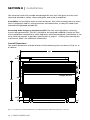
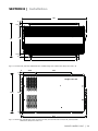
Overall Dimensions
The overall dimensions and the location of the mounting slots are shown in Fig. 8.1 to
8.3 below:
281
4
16.5
Height: 82 mm
200
241
16.5
1.6
4
32
12
162
PST-60S Dimensions (mm): 281 x 241 x 82
12
Fig. 8.1: PST-60S-12E, PST-60S-24E Dimensions and Mounting Slots / Dimensions (mm): 281 x 241 x 82
28 | SAMLEX AMERICA INC.
32
SECTION 8 | Installation
400
4
16.5
Height: 82 mm
200
241
16.5
4
44
282
12
PST-100S Dimensions (mm): 400 x 241 x 82
Fig. 8.2: PST-100S-12E, PST-100S-24E Dimensions and Mounting Slots / Dimensions (mm): 400 x 241 x 82
3
3
80.5
225
Height: 101 mm
282
276
3
415
Fig. 8.3: Dimensions and Mounting Slots for PST-150S-12E, PST-150S-24E and PST-200S-12E, PST-200S-24E /
Dimensions (mm): 415 x 282 x 101
PST-150S & PST-200S Dimensions (mm): 415 x 282 x 101
SAMLEX AMERICA INC. | 29
SECTION 8 | Installation
Mounting Orientation
The unit has air intake and exhaust openings for the cooling fan(s). It has to be mounted
in such a manner so that small objects should not be able to fall easily into the unit from
these openings and cause electrical / mechanical damage. Also, the mounting orientation should be such that if the internal components overheat and melt / dislodge due to
a catastrophic failure, the melted / hot dislodged portions should not be able to fall out
of the unit on to a combustible material and cause a fire hazard. The size of openings
has been limited as per the safety requirements to prevent the above possibilities when
the unit is mounted in the recommended orientations. In order to meet the regulatory
safety requirements, the mounting has to satisfy the following requirements:
- Mount on a non-combustible material.
- The mounting surface should be able to support the weight of the unit
- Mount horizontally on a horizontal surface - above a horizontal surface
(e.g. table top or a shelf).
- Mount horizontally on a vertical surface – The unit can be mounted on a vertical
surface (like a wall) with the fan axis horizontal and the DC input terminals facing
left or right.
WARNING!
Mounting the unit vertically on a vertical surface is NOT allowed (DC terminals
facing up or down). As explained above, this is to prevent falling of objects into
the unit through the fan grille when the fan opening faces up. If fan opening
faces down, hot damaged component may fall out.
DC Side Connections
Preventing DC Input Over Voltage
It is to be ensured that the DC input voltage of this unit does not exceed 16.5 VDC for
the 12 -V battery versions and 33.0 VDC for the 24 -V battery versions to prevent permanent damage to the unit. Please observe the following precautions:
- Ensure that the maximum charging voltage of the external battery charger / alternator / solar charge controller does not exceed 16.5 VDC for the 12V battery version and
33.0 VDC for the 24 -V battery version
- Do not use unregulated solar panels to charge the battery connected to this unit.
Under open circuit conditions and in cold ambient temperatures, the output of the
solar panel may be > 44 VDC. Always use a charge controller between the solar panel
and the battery.
- When using Diversion Charge Control Mode in a charge controller, the solar / wind /
hydro source is directly connected to the battery bank. In this case, the controller will
divert excess current to an external load. As the battery charges, the diversion duty
cycle will increase. When the battery is fully charged, all the source energy will flow
30 | SAMLEX AMERICA INC.
SECTION 8 | Installation
into the diversion load if there are no other loads. The charge controller will disconnect the diversion load if the current rating of the controller is exceeded. Disconnection of the diversion load may damage the battery as well as the inverter or other DC
loads connected to the battery due to high voltages generated during conditions of
high winds (for wind generators), high water flow rates (for hydro generators). It is,
therefore, to be ensured that the diversion load is sized correctly to prevent the above
over voltage conditions.
- Do not connect this unit to a battery system with a voltage higher than the rated battery input voltage of the unit (e.g. do not connect the 12V version of the unit to 24V
or 48V Battery System)
Preventing Reverse Polarity on the Input Side
!
CAUTION!
Damage caused by reverse polarity is not covered by warranty! When making
battery connections on the input side, make sure that the polarity of battery
connections is correct (Connect the Positive of the battery to the Positive terminal of the unit and the Negative of the battery to the Negative terminal of the
unit). If the input is connected in reverse polarity, DC fuse(s) inside the inverter
will blow and may also cause permanent damage to the inverter.
Connection From The Batteries To The DC Input Side Of The Unit –
Wire And External Fuse Sizes
WARNING!
The input section of the inverter has large capacitors connected across the
input terminals. As soon as the DC input connection loop (Battery (+) terminal
► External fuse ► Positive input terminal of the inverter ► Negative input
terminal of the inverter ► Battery (–) terminal) is completed, these capacitors
will start charging and the unit will momentarily draw very heavy current that
will produce sparking on the last contact in the input loop even when the on/
off switch on the inverter is in the off position. Ensure that the external fuse is
inserted only after all the connections in the loop have been completed so that
the sparking is limited to the fuse area.
The flow of electric current in a conductor is opposed by the resistance of the conductor.
The resistance of the conductor is directly proportional to the length of the conductor
and inversely proportional to its cross-section (thickness). The resistance in the conductor produces undesirable effects of voltage drop and heating. Thus, thicker and shorter
conductors are desirable.
SAMLEX AMERICA INC. | 31
SECTION 8 | Installation
The size (thickness / cross-section) of the conductors is designated by AWG (American
Wire Gauge). Please note that a smaller AWG # denotes a thicker size of the conductor
up to AWG #1. Wires thicker than AWG #1 are designated AWG 1/0, AWG 2/0, AWG 3/0
and so on. In this case, increasing AWG # denotes thicker wire.
The DC input circuit is required to handle very large DC currents and hence, the size of
the wires and connectors should be selected to ensure minimum voltage drop between
the battery and the inverter. Thinner wires and loose connections will result in poor
inverter performance and will produce abnormal heating leading to risk of insulation
melt down and fire. Normally, the thickness of the wire should be such that the voltage
drop due to the current & the resistance of the length of the wire should be less than
2%. Use oil resistant, multi- stranded copper wire wires rated at 90ºC minimum. Do not
use aluminum wire as it has higher resistance per unit length. Wires can be bought at a
marine / welding supply store.
Effects of low voltage on common electrical loads are given below:
- Lighting circuits - incandescent and Quartz Halogen: A 5% voltage drop causes an
approximate 10% loss in light output. This is because the bulb not only receives less
power, but the cooler filament drops from white-hot towards red-hot, emitting much
less visible light.
- Lighting circuits - fluorescent: Voltage drop causes a nearly proportional drop in
light output.
- AC induction motors: These are commonly found in power tools, appliances, well
pumps etc. They exhibit very high surge demands when starting. Significant voltage
drop in these circuits may cause failure to start and possible motor damage.
- PV battery charging circuits: These are critical because voltage drop can cause a disproportionate loss of charge current to charge a battery. A voltage drop greater than
5% can reduce charge current to the battery by a much greater percentage.
Fuse Protection In Battery Circuits
A battery is an unlimited source of current. Under short circuit conditions, a battery can
supply thousands of Amperes of current. If there is a short circuit along the length of
the cables that connects the battery to the inverter, thousands of Amperes of current
can flow from the battery to the point of shorting and that section of the wire will become red-hot, the insulation will melt and the cable will ultimately break. This interruption of very high current will generate a hazardous, high temperature, high-energy arc
with accompanying high-pressure wave that may cause fire, damage nearby objects and
cause injury. To prevent occurrence of hazardous conditions under short circuit conditions, an appropriate fuse should be used in the battery circuit that will limit the current, blow in a very short time and quench the arc in a safe manner. For this purpose, UL
Class T fuse or equivalent with Ampere Interrupting Capacity (AIC) of at least 10,000A
should be used (As per UL Standard 248-15). This special purpose current limiting, very
fast acting fuse will blow in less than 8 ms under short circuit conditions. Appropriate
capacity of the above Class T fuse should be installed within 7” of the battery Plus (+)
Terminal. The fuse will require a corresponding fuse holder.
32 | SAMLEX AMERICA INC.
SECTION 8 | Installation
WARNING!
Use of an appropriately sized external fuse as described above is mandatory to
provide safety against fire hazard due to accidental short circuit in the battery
wires. Please note that the DC side fuse(s) inside the unit are designed to provide protection to the internal components of the inverter. These fuses will NOT
blow if there is a short circuit along the length of wires connecting the battery
and the inverter.
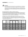
Recommended Sizes of Wires and External Fuses
The following sizes of wires and external fuses are recommended. The distance of 3 ft. /
6 ft. / 10 ft. is the distance between the battery and the inverter. The running length of
routing of the wire should be considered if the wiring run is not straight but circuitous.
The recommended size of wires will limit the voltage drop to 2% of the nominal battery
voltage (0.24V for 12V battery and 0.48V for the 24V battery)
The length of the wire for calculating voltage drop has been taken as 2 times the
distance between the inverter and the battery assuming that 2 lengths of wires (one
Positive and one Negative) are used for the connection. DC resistance values are based
on uncoated, stranded copper conductors at a temperature of 75°C. This temperature is
typical of operating power circuits.
Model No.
Maximum
DC input
current at
rated output
power
3 ft.
6 ft.
PST-200S-12E
240A
AWG #1
PST-200S-24E
120A
AWG #6
PST-150S-12E
200A
AWG #2
PST-150S-24E
100A
AWG #8
PST-100S-12E
160A
AWG #3
PST-100S-24E
80A
AWG #8
PST-60S-12E
80A
PST-60S-24E
40A
Size of Wire
Recommended
SAMLEX
DC Installation
Kit*
10 ft.
Minimum
current
rating of
external
fuse
AWG #3/0
AWG #4/0
240A
DC-2500-KIT
AWG #4
AWG #2
120A
DC-2000-KIT
AWG #2/0
AWG #4/0
200A
DC-2000-KIT
AWG #4
AWG #2
100A
DC-1000-KIT
AWG #1/0
AWG #3/0
160A
DC-2000-KIT
AWG #6
AWG #4
80A
DC-1000-KIT
AWG #6
AWG #3
AWG #1
80A
DC-1000-KIT
AWG #12
AWG #10
AWG #6
40 A
DC-1000-KIT
* Manufactured by Samlex America, Inc. (contains 2 wires and fuse)
SAMLEX AMERICA INC. | 33
SECTION 8 | Installation
i
INFO
4 standard Models of Samlex America, Inc. DC Installation Kits are available to
cover installation requirements of 600 to 3500W inverters. Voltage drop of 2%
or less will be applicable for 3 ft. distance. In some cases, the kits may contain
thicker cables and higher rated fuses than the minimum sizes recommended.
Thicker cables will produce lower voltage drop and hence, will further
improve the overall efficiency. Also, voltage drop may be > 2% in some cases
for distances > 3 ft.
DC Input Terminals for Battery Connection
The DC input terminals for battery connection (8, 9) have cylindrical hole with set screw as
follows: Model PST-60S has an 8 mm cylindrical hole diameter with M-8 set screw and
Models PST-100S-150S and 200S have an 11 mm cylindrical hole diameter with M-8 set screw.
Using Proper DC Wiring Termination
The battery end and the inverter end of the DC input wiring should have proper terminals that will ensure a firm and tight connection. The following Pin Type of terminals are
provided for crimping on to the inverter end of the DC input wires:
- PST-60S:
2 terminals PTNB35-20 for up to AWG #2 or 35 mm2 wires
- PST-100S, PST-150S and PST-200S: 2 terminals PTNB50-20 for up to AWG #1/0 or 50 mm2 wires
Reducing RF Interference
To reduce the effect of radiated interference, twist the DC side cables. To further reduce
RF interference, shield the cables with sheathing /copper foil / braiding.
Taping Battery Cables Together to Reduce Inductance
Do not keep the battery cables far apart. In case it is not convenient to twist the cables,
keep them taped together to reduce their inductance. Reduced inductance of the battery cables helps to reduce induced voltages. This reduces ripple in the battery cables
and improves performance and efficiency.
AC Side Connections
WARNING! Preventing Paralleling of the AC Output
1.The AC output of the inverter cannot be synchronized with another AC
source and hence, it is not suitable for paralleling. The AC output of the inverter should never be connected directly to an electrical breaker panel / load
34 | SAMLEX AMERICA INC.
SECTION 8 | Installation
center which is also fed from the utility power/ generator. Such a connection
will result in parallel operation and AC power from the utility / generator will
be fed back into the inverter which will instantly damage the output section
of the inverter and may also pose a fire and safety hazard. If an electrical
breaker panel / load center is being fed from the utility power / generator
and the inverter is required to feed this panel as backup power source, the
AC power from the utility power/ generator and the inverter should first be
fed to a manual selector switch / Automatic Transfer Switch and the output
of the manual selector switch / Automatic Transfer Switch should be connected to the electrical breaker panel / load center.
2.To prevent possibility of paralleling and severe damage to the inverter, never
use a simple jumper cable with a male plug on both ends to connect the AC
output of the inverter to a handy wall receptacle in the home / RV.
AC Output Connections
For AC output connection, the inverter uses standard, Class 1 grounded mains receptacle
type CEE 7/4 used in Germany, Australia, the Netherlands, Sweden, Norway and Finland.
This type is also known as "Schuko" receptacle (5 in Figs. 6.1, 6.2 and 6.3). A corresponding Class 1 grounded “Schuko” plug Type CEE 7/7 is required on the power cord feeding
the AC devices to be connected to the inverter. The construction of the “Schuko” receptacle and plug is shown at Fig. 8.4 below.
1
2
1.2
1.
European Plug Type CEE-7/7,
also called “Schuko” plug
1.1: Two, non-polarized male
contacts for the two current
carrying conductors
1.2: Two clips for grounding
conductor
2.
Receptacle Type CEE-7/4, also
called “Schuko” receptacle
2.1: Two non-polarized, female
cylindrical contacts for current
carrying conductors
2.2: Spring contacts for
grounding conductor of
the inverter
2.2
1.1
1.2
2.1
Fig. 8.4: Typical “Schuko Type” Receptacle and Plug
In the “Schuko” receptacle (2), two round female cylindrical contacts (2.1) are internally
connected to the current-carrying conductors of the AC output section of the inverter.
The 2 spring contacts (2.2) on the periphery are for “equipment grounding” connec-
SAMLEX AMERICA INC. | 35
SECTION 8 | Installation
tion and are internally connected to the metal chassis of the inverter. The metal chassis
of the inverter is connected to the designated Ground. When the “Schuko” plug (1) of
the power cord of the AC device is plugged into the corresponding “Schuko” receptacle
on the inverter (2 in Fig. 8.4 or 5 in Figs. 6.1, 6.2 and 6.3), the chassis of the AC device is
automatically connected to the designated Ground through the equipment grounding
conductor that is connected to the spring contacts (2.2, Fig 8.4) of the “Schuko” receptacle on the inverter (5 in Figs. 6.1, 6.2 and 6.3)
WARNING!
Because the “Schuko” plug (1) can be inserted in either direction into the
Schuko receptacle (2), the “Schuko” connection system is not polarized (i.e. Line
and Neutral could get reversed). Hence, both the current carrying conductors
are isolated from the chassis of the inverter and there is NO NEUTRAL. Each of
the 2 female contacts (2.1) of the “Schuko” receptacle will be at an elevated
voltage with respect to the chassis of the inverter as follows and should not be
touched:
- PST-60S: 15 VAC to 214 VAC
- PST-100S: 74 VAC to 151 VAC
- PST-150S: 83 VAC to 146 VAC
- PST-200S: 82 VAC to 149 VAC
Please note that the voltage between the 2 female contacts (2.1) of the
“Schuko” receptacle connected to the 2 internal current carrying conductors
of the inverter will be 230 VAC.
Grounding to Earth or to other designated ground
For safety, ground the metal chassis of the inverter to the Earth Ground or to the other
designated ground (For example, in a mobile RV, the metal frame of the RV is normally
designated as the negative DC ground). For PST-60 and PST-100. An equipment grounding bolt with a wing nut (7) has been provided for grounding the metal chassis of the
inverter to the appropriate ground. For PST-150 and PST-200, grounding lug (7) has been
provided.
When using the inverter in a building, connect a 10 mm2 or AWG #8 insulated stranded
copper wire from the above equipment grounding bolt to the Earth Ground connection ( a connection that connects to the Ground Rod or to the water pipe or to another
connection that is solidly bonded to the Earth Ground ). The connections must be tight
against bare metal. Use star washers to penetrate paint and corrosion.
When using the inverter in a mobile RV, connect a 10 mm2 or AWG #8 insulated
stranded copper wire from the above equipment grounding bolt to the appropriate
ground bus of the RV (usually the vehicle chassis or a dedicated DC ground bus). The
connections must be tight against bare metal. Use star washers to penetrate paint and
corrosion.
36 | SAMLEX AMERICA INC.
SECTION 9 | Operation
Powering On The Loads
After the inverter is switched on, it takes a finite time to become ready to deliver full
power. Hence, always switch on the load(s) after a few seconds of switching on the
inverter. Avoid switching on the inverter with the load already switched on. This may
prematurely trigger the overload protection.
When a load is switched on, it may require initial higher power surge to start. Hence, if
multiple loads are being powered, they should be switched on one by one so that the
inverter is not overloaded by the higher starting surge if all the loads are switched on at
once.
Switching The Inverter On/Off
Before switching on the inverter, check that all the AC loads have been switched off. The
on/off switch (1) on the front panel of the inverter is used to switch on and switch off
the inverter. This switch operates a low power control circuitry, which in turn controls all
the high power circuitry.
!
CAUTION!
Please note that the On/Off switch is not switching the high power battery
input circuit. Parts of the DC side circuit will still be alive even when the switch
is in the off position. Hence, disconnect the DC and AC sides before working
on any circuits connected to the inverter.
When the inverter is switched on, the LED indicator (2, Figs. 6.1, 6.2, 6.3) will turn
Green. This LED
indicates that the inverter is operating normally. Under normal operating conditions,
AC output voltage will now be available at the AC outlet (5).
Switch on the AC load(s). The Green LED (2) should remain lighted for normal operation of the load.
Temperature Controlled Cooling Fan
The cooling fan is thermostatically controlled. Temperature of a critical hot spot inside
the inverter is monitored to activate the fan and the over temperature shut-down.
When the temperature of this hot spot reaches 48°C, the fan is switched on. The fan
will be automatically switched off once the hot spot cools down to 42°C. Please note
that the fan may not come on at low loads or if the ambient temperature is cooler. This
is normal.
SAMLEX AMERICA INC. | 37
SECTION 9 | Operation
Indications For Normal Operation
When the inverter is operating normally and supplying AC load(s), the LED (2) will be
green. In case of abnormal operation, other displays and alarms will be activated.
Please see under “Protections Against Abnormal Conditions” .
Optional Wired Remote On/Off Control – Model RC-15
An optional wired Remote Control Model, No. RC-15, is available to enable switching on
and off from a distance of 15 ft. The remote on / off control comes with 15 ft. cable. One
end of the Remote Control is plugged into the 6 Position Modular Jack (10) provided on
the inverter.
To use the Remote Control, the inverter is first required to be switched on from the on/
off switch on the front panel. Now, the inverter can be toggled between on/off conditions by pressing the push button on the remote control.
The LED on the remote control will light when the inverter is in the on condition
No Load Draw (Idle Current)
When the on/off switch is turned on, all the circuitry inside the inverter becomes alive
and the AC output is made available. In this condition, even when no load is being supplied (or, if a load is connected but has been switched off), the inverter draws a small
amount of current from the batteries to keep the circuitry alive and ready to deliver the
required power on demand. This is called the idle current or the no load draw. Hence,
when the load is not required to be operated, turn off the on/off switch on the inverter to prevent unnecessary current drain from the battery.
i
INFO
When the inverter is turned off using the optional Remote Control RC-15, only
the final output section is turned off. The rest of circuits are still in standby
condition. Hence, even in this off condition, there will be a no load current.
Therefore, to prevent any drain from the battery, switch of the inverter from the
on/off switch provided on the front panel of the inverter.
38 | SAMLEX AMERICA INC.
SECTION 10 | Protections
The inverter has been provided with protections detailed below:
Overload / Short Circuit Shut Down
The inverter can provide a higher than normal instantaneous power (< 1 second) limited
to the surge power rating of the inverter. Also, the inverter can provide continuous
power limited to the continuous power rating of the inverter. If there is an overload
beyond these specified limits, the AC output of the unit will be shut down permanently.
Red LED marked “OVER LOAD” (3) will be lighted and Green LED marked “POWER” (2)
will be switched off. The unit will be latched in this shutdown condition and will require
manual reset. To reset, switch off the power On/Off switch, wait for 3 minutes and then
switch on again. Before switching on again, remove the cause of the shutdown.
Warning Alarm - Low DC Input Voltage
The voltage at the DC input terminals (8, 9) will be lower than the voltage at the battery terminals due to voltage drop in the battery wires and connectors. The drop in the
voltage at the DC input terminals of the inverter could be due to lower battery voltage
or due to abnormally high drop in the battery wires if the wires are not thick enough
(Please read “Section 8, Installation; DC SIDE CONNECTIONS; Connection From the Batteries To the DC Input Side of The Unit – Wire and External Fuse Sizes”). If the voltage
at the DC input terminals falls below 10.7V for 12V versions or 21.4V for 24V versions,
a buzzer alarm will be sounded. The Green LED marked “POWER” (2) will continue to
lighted and the AC output voltage would continue to be available. This warning buzzer
alarm indicates that the battery is running low and that the inverter will be shut down
after sometime if the voltage at the inverter terminals further drops to 10 V for 12 V
versions or 20V for 24V versions.
Low DC Input Voltage Shut Down
If the voltage at the DC input terminals falls below 10V for 12V versions or 20V for
24V versions, the AC output is shut down. Buzzer alarm is sounded and the Green LED
marked “POWER” (2) will be switched off. The unit will reset automatically when the
DC input voltage rises > 11.5V for 12V versions and > 23V for 24V versions.
High DC Input Voltage Shutdown
If the voltage at the DC input terminals exceeds 16.5V for 12V versions or 33V for 24V
versions, the inverter will be shut down temporarily. The Green LED marked “POWER”
(2) will be switched off and there will buzzer alarm. The unit will be reset automatically
when the voltage drops down to < 16.5V for 12V versions and to < 33V for 24V versions.
Over-Temperature Shut Down
In case of failure of the cooling fan or in the case of inadequate heat removal due to
higher ambient temperatures / insufficient air exchange, the temperature inside the unit
will increase. The temperature of a critical hot spot inside the inverter is monitored and
at 95°C, the AC output of the inverter is shut down temporarily. The Red LED marked
“OVER TEMP” (4) is lighted and a buzzer is sounded.
SAMLEX AMERICA INC. | 39
SECTION 10 | Protections
The unit will automatically reset after the hot spot has cooled down to 70°C.
Reverse Polarity at the DC Input Terminals
The Positive of the battery should be connected to the Positive DC input terminal of
the inverter (9) and the Negative of the battery should be connected to the Negative
DC input terminal of the inverter (8). A reversal of polarity (the Positive of the battery
wrongly connected to the Negative DC input terminal of the inverter and the Negative
of the battery wrongly connected to the Positive DC input terminal of the inverter) will
blow the external / internal DC side fuses. If the DC side fuse is blown, the inverter will
be dead. The Green LED marked “POWER” (2) will be switched off and there will be no
AC output.
i
INFO
Reverse polarity connection is likely to damage the DC input circuitry. The
internal fuse(s) should be replaced with the correct size of fuse shown under
specifications. If the unit does not work after replacing the fuse(s), it has been
permanently damaged and will require repair / replacement (Please read Section 11 - “Troubleshooting Guide” for more details).
!
CAUTION!
Damage caused by reverse polarity is not covered by warranty! When making
battery connections on the input side, make sure that the polarity of battery
connections is correct (Connect the Positive of the battery to the Positive terminal of the unit and the Negative of the battery to the Negative terminal of the
unit). If the input is connected in reverse polarity, DC fuse(s) inside the inverter
will blow and may also cause permanent damage to the inverter.
40 | SAMLEX AMERICA INC.
SECTION 11 | Trouble Shooting Guide
ISSUE
When switched ON, Green
LED “Power” (2) does not
light. Buzzer is off. There is
no AC output voltage.
POSSIBLE CAUSE
There is no voltage at the
DC input terminals.
REMEDY
Check the continuity of the battery
input circuit.
Check that the external battery fuse is intact.
Replace if blown.
Check that all connections in the battery input
circuit are tight.
Low AC output voltage
(No buzzer alarm).
Polarity of the DC input
voltage has been reversed
that has blown the external / internal DC side fuses
(Note: Reverse polarity
may cause permanent
damage).
Check external and internal fuses. Internal
fuses may be soldered and may not be easily
replaceable. Replace fuses. If unit does not
work, call Technical Support for repair.
Low input voltage at the
inverter terminals and the
load is close to the maximum allowable power.
Check that the battery is fully charged. Recharge, if low.
Check that the battery cables are thick enough
to carry the required current over the required
length. Use thicker cables, if required.
Tighten connections of battery input circuit.
Reduce load.
Buzzer alarm is sounded when
load is switched on. Voltage
at DC input terminals reads
between 10 to 10.7V for 12V
versions and between 20 to
21.4V for 24V versions. Green
LED “Power” (2) is on. AC
output voltage is available.
DC input voltage is less
than 10.7V for 12V versions and less than 21.4V
for 24V versions.
Buzzer alarm is sounded
when load is switched on.
Voltage at the DC input
terminals reads below 10V for
12V versions and below 20V
for 24V versions. Green LED
“Power” (2) is off. There is
no AC output.
Shut-down due to low
DC input voltage - Less
than 10V for 12V versions
and less than 20V for 24V
versions.
There is no AC output.
Green LED “Power” (2) is
off. Buzzer is on.
Shut-down due to high
input DC voltage –
Check that the battery is fully charged. Recharge, if low.
Check that the battery cables are thick enough
to carry the required current over the required
length. Use thicker cables, if required.
Tighten connections of the battery input circuit.
Check that the battery is fully charged. Recharge, if low.
Check that the battery cables are thick enough
to carry the required current over the required
length. Use thicker cables, if required.
Tighten connections of the battery input circuit.
> 16.5V for 12V versions
and > 33V for 24V versions.
Check that the voltage at the DC input terminals is less than 16.5V for 12V versions and less
than 33V for 24V versions.
Ensure that the maximum charging voltage of
the battery charger / alternator / solar charge
controller is below 16.5V for 12V versions and
below 33V for 24V versions.
Ensure that an unregulated solar panel is not
used to charge a battery. Under cold ambient
temperatures, the output of the solar panel
may exceed 22V for 12V system or 42V for
24 V system. Ensure that a charge controller is
used between the solar panel and the battery.
SAMLEX AMERICA INC. | 41
SECTION 11 | Trouble Shooting Guide
ISSUE
AC output shuts down completely. Red LED “Overload”
(3) is lighted. Green LED
“Power” (2) is off.
POSSIBLE CAUSE
Permanent shut-down of
the AC output due to continuous overload beyond
the continuous power
rating of the inverter.
REMEDY
Reduce the load.
The load is not suitable as it requires higher
power to operate. Use an inverter with higher
power rating.
If the unit goes into permanent overload again
after resetting and removing the load completely, the unit has become defective.
Call Technical support.
Note: The unit will be latched in this shutdown condition and will require manual reset.
To reset, switch off the power
On/Off switch, wait for 3 minutes and then
switch on again.
Before switching on again, remove the cause
of the shut-down.
Buzzer alarm is sounded. Red
LED “Over Temp” (4) is on.
There is no AC output.
Shut-down due to over
temperature because of
fan failure or inadequate
cooling as a result of high
ambient temperature or
insufficient air exchange
Check that the fan is working. If not, the fan
control circuit may be defective. Call
Technical Support.
If the fan is working, check that the ventilation
slots on the suction side and the openings
on the discharge side of the fan are not
obstructed.
If the fan is working and the openings are not
obstructed, check that enough cool replacement air is available. Also check that the ambient air temperature is less than 40ºC.
Reduce the load to reduce the heating effect.
After the cause of overheating is removed and
the unit cools down sufficiently, it will reset
automatically.
42 | SAMLEX AMERICA INC.
SECTION 12 | Specifications
Model NO.
PST-60S-12E
PST-60S-24E
output
Power, Continuous
600 Watts
600 Watts
Power, Surge (for <1 sec)
1000 Watts
1000 Watts
Output Voltage
230 VAC +/- 3%
230 VAC +/- 3%
Output Frequency
50 Hz
50 Hz
Output Voltage Waveform
Pure Sine Wave
Pure Sine Wave
Total Harmonic distortion
< 3%
< 3%
INPUT
Input Voltage
10.7 to 16.5 VDC
21.4 to 33 VDC
MAXIMUM INPUT CURRENT
80 A
40 A
Input Current at No Load
< 800 mA
< 600 mA
LOW INPUT VOLTAGE WARNING
ALARM
10.7 V
21.4 V
LOW INPUT VOLTAGE Shut-down
10 V
20 V
High Input Voltage Shut-down
16.5 V
33 V
Operating Ambient Temperature
0 to 40ºC +/- 5ºC
0 to 40ºC +/- 5ºC
Peak Efficiency
85%
85%
COOLING
Temperature Controlled Fan
DC INSTALLATION KIT (OPTIONAL)
DC-1000-KIT
connections
Input
Tubular type screw down terminals
Output
1 Schuko Type of receptacle*
INTERNAL DC Side Input Fuse
40A x 2
20A x 2
REMOTE
RC-15 (optional)
RC-15 (optional)
Dimensions (L x w x H), mm
281 x 241 x 82 281 x 241 x 82
Dimensions (L x w x H) inches
11.1 x 9.5 x 3.2
11.1 x 9.5 x 3.2
Weight, KG
2.5
2.5
Weight, LB
5.4
5.4
General
CE Compliance
SAFETY
Conforms to EN 60950-1
EMI/EMC
EN 55022: Class B; EN 55024; EN 61000-3-2;
EN 61000-3-3
* Schuko Type to Universal Type
adapter is also sold separately.
(Model: 99034)
SAMLEX AMERICA INC. | 43
SECTION 12 | Specifications
Model NO.
PST-100S-12E
PST-100S-24E
output
Power, Continuous
1000 Watts
1000 Watts
Power, Surge (for <1 sec)
2000 Watts
2000 Watts
Output Voltage
230 VAC +/- 3%
230 VAC +/- 3%
Output Frequency
50 Hz
50 Hz
Output Voltage Waveform
Pure Sine Wave
Pure Sine Wave
Total Harmonic distortion
< 3%
< 3%
input
Input Voltage
10.7 to 16.5 VDC
21.4 to 33 VDC
maximum input current
160 A
80 A
Input Current at No Load
LOW INPUT VOLTAGE WARNING
ALARM
LOW INPUT VOLTAGE Shut-down
< 1.2 A
< 0.8 A
10.7 V
21.4 V
10 V
20 V
High Input Voltage Shut-down
16.5 V
33 V
Operating Ambient Temperature
0 to 40ºC +/- 5ºC
0 to 40ºC +/- 5ºC
Peak Efficiency
85%
85%
COOLING
Temperature Controlled Fan
DC INSTALLATION KIT (OPTIONAL)
DC-2000-KIT
DC-1000-KIT
connections
Input
Tubular type screw down terminals
Output
1 Schuko Type of receptacle*
internal DC Side Input Fuse
40 A x 4
20 A x 4
REMOTE
RC-15 (optional)
RC-15 (optional)
Dimensions (L x w x H), MM
400 x 241 x 82
400 x 241 x 82
Dimensions, (L x w x H), inches
15.7 x 9.5 x 3.2
15.7 x 9.5 x 3.2
Weight, KG
4
4
Weight, LB
8.8
8.8
general
ce compliance
SAFETY
Conforms to EN 60950-1
EMI/EMC
EN 55022: Class B; EN 55024; EN 61000-3-2;
EN 61000-3-3
* Schuko Type to Universal Type
adapter is also sold separately.
(Model: 99034)
44 | SAMLEX AMERICA INC.
SECTION 12 | Specifications
Model NO.
PST-150S-12E
PST-150S-24E
output
Power, Continuous
1500 Watts
1500 Watts
Power, Surge (for <1 sec)
3000 Watts
3000 Watts
Output Voltage
230 VAC +/- 3%
230 VAC +/- 3%
Output Frequency
50 Hz
50 Hz
Output Voltage Waveform
Pure Sine Wave
Pure Sine Wave
Total Harmonic distortion
< 3%
< 3%
input
Input Voltage
10.7 to 16.5 VDC
21.4 to 33 VDC
maximum input current
200 A
100 A
Input Current at No Load
< 1.6 A
< 1.0 A
LOW INPUT VOLTAGE WARNING ALARM
10.7 V
21.4 V
LOW INPUT VOLTAGE Shut-down
10 V
20 V
High Input Voltage Shut-down
16.5 V
33 V
Operating Ambient Temperature
0 to 40ºC +/- 5ºC
0 to 40ºC +/- 5ºC
Peak Efficiency
85%
85%
COOLING
2 x Temperature Controlled Fans
DC INSTALLATION KIT (OPTIONAL)
DC-2000-KIT
DC-1000-KIT
connections
Input
Tubular type screw down terminals
Output
2 Schuko Type of receptacles*
internal DC Side Input Fuse
40 A x 5
20 A x 5
REMOTE (OPTIONAL)
RC-15
RC-15 Dimensions, (L x w x H)
415 x 282 x 101
415 x 282 x 101
Dimensions, (L x w x H)
16.3 x 11.1 x 4
16.3 x 11.1 x 4
Weight, KG
5.7
5.7
Weight, LB
12.7
12.7
general
ce compliance
SAFETY
Conforms to EN 60950-1
EMI/EMC
EN 55022: Class B; EN 55024; EN 61000-3-2;
EN 61000-3-3
* Schuko Type to Universal Type
adapter is also sold separately.
(Model: 99034)
SAMLEX AMERICA INC. | 45
SECTION 12 | Specifications
Model NO.
PST-200S-12E
PST-200S-24E
2000 Watts
2000 Watts
output
Power, Continuous
Power, Surge (for <1 sec)
4000 Watts
4000 Watts
Output Voltage
230 VAC +/- 3%
230 VAC +/- 3%
Output Frequency
50 Hz
50 Hz
Output Voltage Waveform
Pure Sine Wave
Pure Sine Wave
Total Harmonic distortion
< 3%
< 3%
input
Input Voltage
10.7 to 16.5 VDC
21.4 to 33 VDC
maximum input current
240 A
120 A
Input Current at No Load
LOW INPUT VOLTAGE WARNING
ALARM
LOW INPUT VOLTAGE Shut-down
< 1.6 A
< 1.0 A
10.7 V
21.4 V
10 V
20 V
High Input Voltage Shut-down
16.5 V
33 V
Operating Ambient Temperature
0 to 40ºC +/- 5ºC
0 to 40ºC +/- 5ºC
Peak Efficiency
85%
85%
COOLING
2 x Temperature Controlled Fans
DC INSTALLATION KIT (optional)
DC-2500-KIT
DC-2000-KIT
connections
Input
Tubular type screw down terminals
Output
2 Schuko Type of receptacles*
internal DC Side Input Fuses
40 A x 6
20 A x 6
REMOTE (optional)
RC-15 RC-15
Dimensions (L x w x H), mm
415 x 282 x 101
415 x 282 x 101
Dimensions (L x w x H), inches
16.3 x 11.1 x 4
16.3 x 11.1 x 4
Weight, KG
5.9
5.9
Weight, LB
13
13
general
ce compliance
SAFETY
Conforms to EN 60950-1
EMI/EMC
EN 55022: Class B; EN 55024; EN 61000-3-2;
EN 61000-3-3
* Schuko Type to Universal Type
adapter is also sold separately.
(Model: 99034)
46 | SAMLEX AMERICA INC.
SECTION 13 | Warranty
2 Year limited warranty
The PST-60S-12E / PST-60S-24E; PST-100S-12E / PST-100S-24E; PST-150S-12E / PST-150S-24E;
and PST-200S-12E / PST-200S-24E Series Inverters are manufactured by Samlex America,
Inc. (the “Warrantor“) is warranted to be free from defects in workmanship and materials under normal use and service. The warranty period is 2 years for the United States
and Canada, and is in effect from the date of purchase by the user (the “Purchaser“).
Warranty outside of the United States and Canada is limited to 6 months. For a warranty
claim, the Purchaser should contact the place of purchase to obtain a Return Authorization Number.
The defective part or unit should be returned at the Purchaser’s expense to the authorized location. A written statement describing the nature of the defect, the date of purchase, the place of purchase, and the Purchaser’s name, address and telephone number
should also be included.
If upon the Warrantor’s examination, the defect proves to be the result of defective
material or workmanship, the equipment will be repaired or replaced at the Warrantor’s option without charge, and returned to the Purchaser at the Warrantor’s expense.
(Contiguous US and Canada only)
No refund of the purchase price will be granted to the Purchaser, unless the Warrantor
is unable to remedy the defect after having a reasonable number of opportunities to do
so. Warranty service shall be performed only by the Warrantor. Any attempt to remedy
the defect by anyone other than the Warrantor shall render this warranty void. There
shall be no warranty for defects or damages caused by faulty installation or hook-up,
abuse or misuse of the equipment including exposure to excessive heat, salt or fresh
water spray, or water immersion.
No other express warranty is hereby given and there are no warranties which extend
beyond those described herein. This warranty is expressly in lieu of any other expressed
or implied warranties, including any implied warranty of merchantability, fitness for the
ordinary purposes for which such goods are used, or fitness for a particular purpose, or
any other obligations on the part of the Warrantor or its employees and representatives.
There shall be no responsibility or liability whatsoever on the part of the Warrantor or
its employees and representatives for injury to any persons, or damage to person or
persons, or damage to property, or loss of income or profit, or any other consequential
or resulting damage which may be claimed to have been incurred through the use or
sale of the equipment, including any possible failure of malfunction of the equipment,
or part thereof. The Warrantor assumes no liability for incidental or consequential damages of any kind.
Samlex America Inc. (the “Warrantor”)
www.samlexamerica.com
SAMLEX AMERICA INC. | 47
Contact
Information
Toll Free Numbers
Ph: 800 561 5885
Fax: 888 814 5210
Local Numbers
Ph: 604 525 3836
Fax: 604 525 5221
Website
www.samlexamerica.com
USA Shipping Warehouse
Kent WA
Canadian Shipping Warehouse
Delta BC
Email purchase orders to
[email protected]
11001-PST-60-100-150-200S-12-24E-0412