1
™
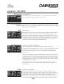
FDS-366T OMNIDRIVE
User Manual
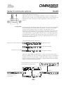
Connect here first...
FDS-366T
ZM10019 issue 4 CB/PW/DN/DP/JWK
Software version 2.00
IMPORTANT SAFETY INFORMATION
DO NOT REMOVE COVERS.
NO USER SERVICABLE PARTS INSIDE.
REFER SERVICING TO QUALIFIED SERVICE PERSONNEL.
THIS EQUIPMENT MUST BE EARTHED.
IT SHOULD NOT BE NECESSARY TO REMOVE ANY PROTECTIVE
EARTH OR SIGNAL CABLE SHIELD CONNECTIONS TO PREVENT
GROUND LOOPS. ANY SUCH DISCONNECTIONS ARE OUTSIDE
THE RECOMMENDED PRACTISE OF BSS AUDIO AND WILL
RENDER ANY EMC OR SAFETY CERTIFICATION VOID.
REGULATORY INFORMATION
This equipment has been tested and found to comply with the following European and International Standards
for Electromagnetic Compatibility and Electrical Safety:
Emmissions (EU):
Generic Immunity (EU):
Mains Harmonics (EU)
Voltage Fluctuations (EU)
Electrical Safety (EU):
Electrical Safety (USA):
EN55013+A12+A13
EN50082-1
EN61000-3-2
EN61000-3-3
EN60065+A11
UL813/ETL
(1990)
(1992)
(1995)
(1995)
(1993)
(1996)
For continued compliance with international EMC legislation ensure that all input and output cables are wired
with the cable screen connected to Pin 1 of the XLR connectors.
The input XLR Pin 1 is connected to the chassis via a low value capacitor, providing high immunity from ground
loops whilst ensuring good EMC performance.
The FDS-366T Omnidrive was designed and developed by BSS Audio, Hertfordshire, UK.
In keeping with our policy of continued improvement, BSS Audio reserves the right to alter specifications
without prior notice.
-2-
FDS-366T
Contents
FDS-366T Omnidrive compact plus
1.0 Primary Checks ......................................................................................... 8
2.0 Installation ................................................................................................. 8
3.0 Warranty Information ............................................................................... 9
About the FDS-366T Omnidrive Compact Plus ............................... 10
4.0 Introduction ............................................................................................ 11
5.0 Features .................................................................................................... 12
What is DEQ? ................................................................................................. 16
6.0 Dynamic Equalisation .............................................................................. 16
Notes and Uses .................................................................................................................. 17
7.0 Crossover Shapes and Frequencies .......................................................... 19
Thiele Crossover ................................................................................................................ 21
Crossover comparison chart ............................................................................................... 22
Phase Compensation .......................................................................................................... 23
Stereo 3-Way with mono sub-bass. ................................................................ 24
8.0 Typical Applications ................................................................................. 24
6-Way zoning distribution .............................................................................. 25
LCR cinema systems (3x2-way)....................................................................... 25
Triple Bi-amp (Stage monitors) ........................................................................ 25
Mono 6-way ................................................................................................... 26
Stereo 6-way (example) .................................................................................. 26
9.0 Front Panel ............................................................................................... 27
10.0 Rear panel .............................................................................................. 29
Using the FDS-366T Omnidrive Compact Plus ............................... 30
Voltage setting ................................................................................................ 31
11.0 Connections - Mains Power .................................................................. 31
AC Power fusing ............................................................................................ 32
Connections - Audio...................................................................................... 33
Balanced wiring .................................................................................................................. 33
-3-
FDS-366T
Unbalanced wiring ............................................................................................................. 34
MIDI ................................................................................................................................... 35
RS232 Serial ....................................................................................................................... 35
RS485 Serial ....................................................................................................................... 35
Program Select Port ............................................................................................................. 36
12.0 Navigation .............................................................................................. 37
The Navipad ................................................................................................... 37
The Rotary Encoder ........................................................................................ 37
13.0 Default Screen ....................................................................................... 38
14.0 Quick Start Guide .................................................................................. 39
Keep relative delays while delaying a group ....................................................................... 44
Name a band ..................................................................................................................... 44
15.0 Quick Reference - How to ... ................................................................. 44
Use delays for driver alignment .......................................................................................... 44
Make a band full range ...................................................................................................... 45
Add EQ for Constant Directivity horns................................................................................ 45
Load custom logos ............................................................................................................. 45
Programming functions in depth ..................................................... 46
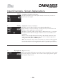
Recalling a Program ........................................................................................................... 47
16.0 Program Functions - Recall .................................................................... 47
Storing a Program ............................................................................................................... 48
Program Functions - Store.............................................................................. 48
Store Lock .......................................................................................................................... 48
Program lock ...................................................................................................................... 49
Store Type .......................................................................................................................... 49
Delete Program .................................................................................................................. 50
Card types .......................................................................................................................... 51
Compatible Cards .............................................................................................................. 51
Storage life ......................................................................................................................... 51
PC Card format .................................................................................................................. 51
17.0 PC Card Usage ....................................................................................... 51
FDS-355 compatibility ....................................................................................................... 52
Computer compatibility...................................................................................................... 53
-4-
FDS-366T
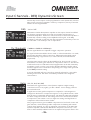
18.0 Utilities .................................................................................................. 53
1. Configuration.................................................................................................................. 54
2. Stereo Link ...................................................................................................................... 54
3. Sum Type........................................................................................................................ 54
5. Phase Comp ................................................................................................................... 55
4. Xover Adjust ................................................................................................................... 55
6. Alignment Assistant ......................................................................................................... 56
Method .............................................................................................................................. 56
Microphone placement and connection .............................................................................. 56
Procedure ........................................................................................................................... 57
Selecting bands to measure ................................................................................................. 57
Adjusting the stimulus level ................................................................................................. 58
Notes ................................................................................................................................. 58
7. Delay Corrn (Correction) ................................................................................................. 60
8. Temperature.................................................................................................................... 61
9. Limit units ....................................................................................................................... 61
10. Delay units ................................................................................................................... 61
11. Brightness ..................................................................................................................... 61
12. Contrast ........................................................................................................................ 61
14. Owner lock .................................................................................................................. 62
13. Lock out ....................................................................................................................... 63
Setting up 'Owner' Locks .................................................................................................... 63
Storing Owner Programs ..................................................................................................... 64
Adding further locks ........................................................................................................... 64
15. OEM Lock .................................................................................................................... 65
Storing OEM Programs ........................................................................................................ 66
Adding further locks ........................................................................................................... 66
OEM & Owner Locks .......................................................................................................... 67
Configuration parameter note .............................................................................................. 67
Lockable Utilities ................................................................................................................ 67
17. Serial Port ..................................................................................................................... 68
18. MIDI Mode ................................................................................................................... 68
16. Input A/AES .................................................................................................................. 68
19. MIDI Channel ............................................................................................................... 69
20. MIDI Dump .................................................................................................................. 69
23. Delete Program ............................................................................................................. 70
21. Backup & Swap ............................................................................................................ 70
22. Store Gain Trims ............................................................................................................ 70
24. Format Card.................................................................................................................. 70
19.0 Input Channels ....................................................................................... 71
2. Delay ............................................................................................................................. 72
3. EQ Bypass ...................................................................................................................... 72
-5-
FDS-366T
4. Dynamic EQ ................................................................................................................... 72
1. Gain ............................................................................................................................... 72
DEQ ................................................................................................................................... 73
Thr (Threshold) ................................................................................................................... 73
Ratio .................................................................................................................................. 73
Attack and Release ............................................................................................................. 74
Atk (Attack) ......................................................................................................................... 74
Rel (Release) ....................................................................................................................... 74
20.0 Output Channels .................................................................................... 75
1. Name ............................................................................................................................. 76
2. Source ............................................................................................................................ 76
3. Low Shape ..................................................................................................................... 77
Low Freq/Xover .................................................................................................................. 77
4. High shape ..................................................................................................................... 77
High Freq/Xover ................................................................................................................. 77
6. Band gain ....................................................................................................................... 78
5. Phase ............................................................................................................................. 79
Polarity .............................................................................................................................. 79
7. Limiter ........................................................................................................................... 79
Over (Overshoot) ............................................................................................................... 79
Thr (Threshold) ................................................................................................................... 79
Rel (Release) ...................................................................................................................... 79
Atk (Attack) ........................................................................................................................ 79
Delay ................................................................................................................................. 80
EQ Bypass....................................................................................................... 80
Delay link .......................................................................................................................... 80
DEQ ................................................................................................................................... 81
Thr (Threshold) ................................................................................................................... 81
Ratio .................................................................................................................................. 81
Attack and Release ............................................................................................................. 82
Atk (Attack) ........................................................................................................................ 82
Rel (Release) ...................................................................................................................... 82
Outputs - EQ .................................................................................................. 83
EQ shape ........................................................................................................................... 84
Frequency .......................................................................................................................... 85
Width ................................................................................................................................. 85
Cut/Boost ........................................................................................................................... 85
-6-
FDS-366T
Reference Section ........................................................................... 86
21.0 Serial Communications ......................................................................... 87
MIDI ................................................................................................................................... 87
MIDI with PC Control.......................................................................................................... 88
Synchronous Control .......................................................................................................... 88
RS232 ................................................................................................................................ 89
RS485 & Multidrop ............................................................................................................. 90
22.0 Troubleshooting ..................................................................................... 94
23.0 FDS-366T Omnidrive MIDI Implementation ....................................... 95
A.1 FDS-366T MIDI Implementation ............................................................ 95
24.0 Default Configuration Settings ............................................................... 96
25.0 Filter Allocations .................................................................................... 98
26.0 Specifications and Block Diagram ......................................................... 99
27.0 Block Diagram ..................................................................................... 101
28.0 User Notes ........................................................................................... 102
-7-
FDS-366T
1.0
✓
Primary Checks
As part of BSS' system of quality control, this product is carefully inspected
before packing to ensure flawless appearance.
After unpacking the unit, please inspect for any physical damage and retain the
shipping carton and ALL relevant packing materials for use should the unit
need returning.
In the event that damage has occurred, please notify your dealer immediately,
so that a written claim to cover the damages can be initiated.
Please fill in the warranty details on the form opposite for future reference.
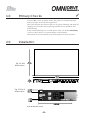
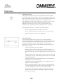
2.0
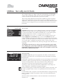
Installation
Fig 3.1 Unit
dimensions.
Fig 3.2 Rack
dimensions.
Note all dimension in mm
-8-
FDS-366T
3.0
Warranty Information
✍
When sold to an end user by BSS Audio or a BSS Audio Authorised Reseller,
this unit is warranted by the seller to the purchaser against defects in
workmanship and the materials used in its manufacture for a period of one
year from the date of sale.
Faults arising from misuse, unauthorised modifications or accidents are not
covered under this warranty. No other warranty is expressed or implied.
If the unit is faulty it should be sent to the seller of the equipment, in its original
packaging with shipping prepaid. The unit will be returned to you when the
repair has been completed. If the unit was purchased in the European Union,
you may, as an alternative, return the unit to any other BSS distributor in the
European Union.
You should include a statement listing the faults found. The unit’s serial
number must be quoted in all correspondence relating to a claim.
IMPORTANT
We recommend that you record your purchase information here for future
reference.
Unit Serial Number:
Dealer Name:
Dealer Address:
Post/Zip Code:
Dealer Phone Number:
Dealer Contact Name:
Invoice/Receipt Number:
Date of Purchase:
Comments or questions regarding the FDS-366T or other BSS products? Contact
us at this address:
+
✆
BSS Audio
Cranborne House
Cranborne Road
Potter Bar
Herfordshire
EN6 3JN
England
Phone (+44) (0)1707 660667. Fax (+44) (0)1707 660742.
Web site, www.bss.co.uk
-9-
FDS-366T
About the
FDS-366T
Omnidrive
Compact
Plus
- 10 -
FDS-366T
4.0
Introduction
Introducing the BSS Audio FDS-366T Omndrive Compact Plus, an incredibly
powerful loudspeaker management system in only 1U of rackspace! Based on
BSS Audio's many years of experience building analogue processing devices
for the live sound and installed markets, the FDS-366T Omnidrive is an 'all in
one' solution for system crossover assignment, EQ, delay and dynamics
control.
Processing power
Using custom designed digital signal processing (DSP) technologies BSS Audio
are able to deliver far more capabilities in one box than was realisable from a
whole rack of analogue equipment only a few years ago. Also as all the
processing on the audio signal is kept in the digital domain added noise and
phase anomalies usually expected with analogue equivalents are virtually
eliminated. The signals are processed at 24bit, 96kHz resolution to achieve a
dynamic range greater than 112dB to ensure the best possible audio quality for
your system.
Security
Moreover, the comprehensive security features included in the FDS-366T
enable the unit to be set up with varying degrees of access to its functionality
applied and protected by passwords. Indeed the whole unit can be locked
totally to prevent tampering, in installed applications for example.
Routing
An arrangement of 3 inputs and 6 outputs and an additional internal sum of
inputs A&B, A+B+C, pre or post input EQ can be matrixed in various
combinations to provide a complete loudspeaker management system with
integral crossovers, delays, dynamic EQ, and protection limiters.
Applications
The flexibility of the FDS-366T enables it to be employed for many system
uses, such as complete 3 way stereo setups or a 2 way LCR combination.
Equally FDS-366T Omnidrives can be stacked to run larger 5 and 6 way
systems and more.
In stage monitor systems the FDS-366T can function as a triple bi-amp
crossover with delay, limiters and EQ. On-stage 'hotspots' caused by monitors
with identical signals can be eliminated by applying small delays between
wedges.
Furthermore, the FDS-366T can function as a distribution unit to multizone
systems where crossovers may be passive or local to the loudspeaker. In this
case, the provision of delays and EQ can radically enhance such a system
while reducing both processing costs and required rack space.
Upgradeable operating system
The system operating software is held in flash EPROM, which means that
upgrading to new software is easy - either via PC card or from a PC via the
MIDI or RS-232 ports.
Memorising Setups
60 internal program locations are available to the user for storing system
setups, which may be generic system programs or complete venue settings.
These memories may be stored onto a PC card for backup or archiving.
- 11 -
FDS-366T
5.0
Features
✓
✓
Individual keys to select input and output channels for editing.
✓
✓
✓
Comprehensive output limiters on each band (mid-filter).
Crossover slopes of 6,12, 18, 24 or 48dB per octave.
Filter types:Butterworth, Bessel, Linkwitz-Riley and WHISEWORKSNTM*.
Equalisers and 'dynamic' equalisers on each input and output.
High resolution input and output delays up to 2.6 seconds in
approximately 11 microsecond steps.
✓
✓
Input LED metering, showing signals from -12dB to clip level, and SIG.
Output LED metering, showing signals from -20dB to +6dB over limit
threshold, and SIG.
✓
✓
✓
Front panel output level trims and mutes.
Polarity reverse on each output.
Phase adjustment for each crossover point, and phase compensation
defeat.
✓
✓
PC card port for storage and recall of program settings
Electronically balanced inputs and outputs with transformer output
option.
✓
✓
✓
✓
✓
MIDI, RS-232, RS-485 and program change ports on rear panel.
✓
Temperature based delay correction.
96kHz sample rate and 24bit encoding/decoding for audio excellence.
AES/EBU digital input for direct digital feeds into Omnidrive.
Alignment Assistant for setting up cabinet driver alignments.
Comprehensive system security with control lock out, programmable
'Owner' and 'OEM' locks, and 'Safe' mode available for complete
system lock out.
If you are familiar with the FDS-355 Omnidrive then look at the extra benefits
that the FDS-366T brings, an extra output channel, dynamic equalisation,
Thiele crossover shape and 96kHz audio quality to start with!
* The words "WHISEWORKS", "Neville Thiele Method" and NTM logotype are
trademarks of Precision Audio Pty. Ltd (registration pending). Manufactured
under license from Precision Audio Pty. Ltd. International Patents Pending.
- 12 -
FDS-366T
Features
Some of the features are explained in greater detail here.
•
96kHz Sample rate
The FDS-366T operates the A-D and D-A converters and the Digital
Signal Processing (DSP) at a sample rate of 96kHz. The use of a higher
Nyquist frequency enables the audio bandwidth to extend all the way
up to 40kHz. With this extra frequency response we have also been
able to incorporate more accurate filter sets for a more natural, open
sound.
There is also benefit from the improved filter response shapes when the
nyquist frequency (the maximum frequency of which the DSP can
correctly process the signal), moves up from 24kHz to 48kHz. Low-pass
filters and bell filters then retain their magnitude and phase response
shapes more accurately.
•
AES/EBU digital input
The FDS-366T is equipped as standard with a stereo AES/EBU digital
audio input which will accept sample rates of 44.1, 48, 88.2 and 96kHz.
44.1 and 48kHz modes are sample-rate converted and the waveform
interpolated to 88.2 and 96kHz respectively within the FDS-366T so
that all of the filtering is done at the higher rate to get more of the
benefits of the increased sample rate. Using the AES input the
realisable dynamic range is increased to greater than 117dB.
•
Phase matching
This feature maintains the inter-band phase relationship true to the
crossover type selected (Bessel, Butterworth, L-R etc), regardless of any
interference from far-end crossover filtering.
In 2-way crossovers, this is not an issue since each band has just one
high-pass or low-pass filter. Three or more bands however, cause at least
one band to have both low-pass and high-pass filters which react with
one another, so disturbing the correct phase relationship at the crossover
point. This can result in poor combining of adjacent crossover bands,
resulting in an irregular frequency response and non-uniform polar
characteristics.
The Phase Matching technique used in the FDS-366T eliminates this
problem by compensating for these phase anomalies. The phase
compensation can be bypassed if not required.
- 13 -
FDS-366T
Features
•
Alignment Assistant
The Alignment Assistant is an advanced loudspeaker measurement
function built-in to the FDS-366T for directly measuring the delay and
phase relationships between drivers (using a measurement microphone),
and automatically adjusting the settings to accommodate these.
@
The Alignment Assistant has the ability to ‘see’ past the crossover filters,
and is thus able to compensate for the drivers and enclosures
themselves, leaving the crossovers to do exactly what they were
intended to do - presenting a precisely aligned acoustic wavefront.
The Alignment Assistant can measure and compensate for:
•
-
Physical alignment of drivers within an enclosure.
-
Driver or enclosure phase anomalies near the crossover point.
-
Relative distance correction of arrayed boxes.
Advanced Limiters
Driver protection limiters have always been a balance between
protection, transparency and the preservation of maximum power. The
all-new limiter algorithm in the FDS-366T not only allows the user the
freedom to change the way the compromises are balanced, but
introduces several new features which enable the requirements to be
met with less sacrifice.
-
Feed-forward design for better stability.
-
Adaptive attack, so that attack time is reduced the further over
threshold the signal strays. This helps to preserve transparency for
light overshoots, but acts more aggressively if the signal strays too
far.
-
Adaptive release, so that short-term overshoots do not reduce the
average power output, whilst keeping distortion low on sustained
over-threshold signals.
-
Adjustable attack speed (fast/med/slow/dual) - but still related to
the high-pass crossover frequency.
-
Adjustable release speed (fast/med/slow) - but still related to the
high-pass crossover frequency.
-
Brickwall overshoot limiter. This is actually a soft-clipper which
constrains signals which overshoot during the attack phase. The
user has adjustable ‘overshoot’ from 1 to 12dB (and off).
-
Dual time-constant mode for giving simultaneous protection
against short-term mechanical damage or clipping, and longer
term thermal damage.
- 14 -
FDS-366T
Features
•
Safe mode
The FDS-366T has a hidden function called 'Safe'. 'Safe' mode is intended to
be used as a complete lock-out for installations or as the ultimate protection
for hire systems etc.
When SAFE mode is switched on, all controls are disabled, the screen blanks
and the backlight is dimmed. The input and output meters will still display the
existence of signal being processed through the unit but no one can change
any values within the unit.
! Any adjustments made to the gain controls whilst in 'Safe' mode will not be
heard until 'Safe' is turned off.
! As the 'Safe' mode is intended for ultimate security, the details of its use
cannot be published here. Please consult your dealer for further information
on Safe mode.
- 15 -
FDS-366T
6.0
Typical Applications
j
The FDS-366T has three inputs: A, B, C. An internal mono sum of inputs is also
available for routing to any of the outputs. Many combination of routing inputs
to outputs is available, and the FDS-366T can be configured as a stereo or
mono device. The basic configurations are selected in the Utilities and the
following examples are based upon these as possible likely setups.
Stereo 3-Way with
mono sub-bass.
Systems can be run in one of two stereo 3-way modes.
LLMMHH allows compatability with the 355, now having two low outputs.
LMHLMH set up is an alternative, allowing users to choose the setup they are
most familiar with.
Stereo Link "On" mode allows the same parameters on the left and right
channels to be adjusted simultaneously, and any edits made whilst unlinked
preserve the left/right difference as an offset.
Note: The stereo pairs change appropriately for LLMMHH and LMHLMH
modes.
- 16 -
FDS-366T
j
Typical Applications
Triple Bi-amp
(Stage monitors)
The FDS-366T can provide 3 channels of bi-amp crossover for monitor racks
with EQ, delays, and limiters. With so much EQ available in the FDS-366T, it
is easy to assign 12 bands of EQ to the input, as well as EQ to the output
bands, saving the need for external EQ.
In LHLHLH mode by default, input A feeds outputs 1 and 2, input B feeds
outputs 3 and 4, and input C feeds outputs 5 and 6.
In this mode, it is possible to remove ‘hot spots’ on stage. Where the same mix
is sent to a number of performers, interaction between wedges can create lobes
of high intensity sound causing confusion. Using a fine delay to shift wedge
feeds can move these 'hot-spots' to less sensitive areas on stage.
LCR cinema
systems (3x2-way)
6-Way zoning
distribution
A similar configuration to the triple 2-way setup above.
The FDS-366T can be also be used as a zone distribution system, without
using any of its crossover facilities. Using this mode, a common input signal
can be routed to up to 6 separate outputs, each with delays, EQ and limiters.
Typical uses for this mode would include feeding a number of under-balcony
loudspeakers with integral passive crossovers, using the delays of the FDS366T for time correction, and EQ for tuning response.
For this application set the configuration to Mono and each output should be
full range (unless you particularly want to band restrict the outputs). Use the
'Xover Freq' screens in the output channel to set each band edge to be 'OUT'.
- 17 -
FDS-366T
j
Typical Applications
Mono 6-way
In the mono mode, the FDS-366T can provide a full 6-way system. It can also
function as a 5-way system fed from input A, with an independent sub-bass
output fed from the sum of inputs A & B or input C.
Stereo 6-way
(example)
Two FDS-366Ts working in this mode can form a stereo 6-way system. For
example purposes only, in the diagram below the first FDS-366T is running a 5
way system with the mono sub bass derived from the sum of inputs A and B.
The second FDS-366T has its mono sub bass output fed from a dedicated
output on the desk running into input C.
- 18 -
FDS-366T
7.0
Crossover Shapes and Frequencies
It is not possible to provide one loudspeaker driver to cover all audible
frequencies. Even if the frequency response could be achieved, the large size
of the driver required to shift enough air at low frequencies would offer an
impossibly directional beam at high frequencies because at small wavelengths,
the differing path lengths from the extremities of the diaphragm to the listener
would cause cancellations off-axis. Therefore, it is necessary to use more than
one driver and to split the bands with an electrical filter or crossover. This
filtering can be done by passive, active or digital means, external to or within
the loudspeaker cabinet.
Ideally, the filtering is done so that when acoustically combined, the drivers
produce a constant output across the required range of frequencies.
Additionally, the signal phase behavior with frequency should offer smooth
transitions across all the drivers to achieve a constant group delay. Another
important consideration is that the crossover should control the beaming
properties, also known as the polar response, so that listeners off-axis do not
hear anomalies in the sound range. Many crossover filter designs do not
achieve these goals.
Finally, the signal should be quickly attenuated outside the optimum band of
operation for each driver to avoid driver anomalies such as resonance and
over-excursion distortion at low frequencies. In these instances some crossover
shapes have limitations.
The FDS-366T allows full control over each high and low pass filter of a
crossover segment in shape, slope and frequency. Graphically these
parameters are labelled as below.
Filter Edge Identification
- 19 -
FDS-366T
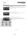
Crossover Shapes and Frequencies
The graphs on this page show the filter slope curves with associated crossover points in order to aid the sound
technician in the choice of filter shape to use for the desired result between speaker drivers of differing
specifications and characteristics.
5.0000
Linkwitz-Riley 12, 24 & 48dB/Octave Slopes.
For many years Linkwitz-Riley crossovers have
been the 'industry standard' as they offered the
best compromise between the parameters
discussed earlier. They retain good polar
response, sum to a flat amplitude response and
retain correct polarity across the 24dB/octave and
48dB/octave slopes. The 12dB/octave variant
generally needs a polarity inversion to achieve the
required results. They have been the usual choice
for most applications.
0.0
-5.000
-10.00
-15.00
-20.00
-25.00
-30.00
-35.00
-40.00
-45.00
-50.00
20
100
1k
10k
20k
Butterworth 6, 12, 18, 24 & 48dB/Octave Slopes.
The even order Butterworth crossovers (12, 24,
48dB/octave) exhibit a symmetrical polar response
due to identical phase responses in the Hi and Lo
bands. There is an issue with a 3dB peak in the
amplitude response at the crossover frequency but
this can be corrected with equalisation. In
contrast, the odd order Butterworths (6 & 18dB/
octave) sum to a flat amplitude response but suffer
asymmetry in their polar response that changes as
the signal moves through the crossover point. This
'tilt' can produce colouration and is dependant on
the listening position. These also require polarity
inversion for correct response.
5
0
-
-
-
-
-
-
-
-
-
-
Bessel 12 & 24dB/Octave Slopes.
Standard Bessel filters when used for crossover
duties do not provide immediately acceptable
results due to deficiencies in their amplitude
response. Due to this only 4th and 2nd order (Bes
24 & 12) alignments were considered to be
acceptable for inclusion. The 12dB/octave
version will require a polarity inversion of one
band for proper summation.
- 20 -
FDS-366T
Crossover Shapes and Frequencies
WHISEWORKS-NTM
Crossover
The WHISEWORKS-Neville Thiele Method (NTM) crossover filter is a new
type of electrical/acoustical filter offering significant performance advantages
over all previous crossover filter types in audio applications. The filter was
developed by Neville Thiele (pronounced “Teel”).
This filter uses a unique notched response to achieve a very steep roll-off rate
outside the passband. There are two choices of NTM crossover included in
the FDS-366T; a 4th order (NTM 36) and an 8th order (NTM52). The 4th order
shape offers exceptional group delay flatness with a roll-off of at least 36dB/
octave. The 8th order version offers the steepest roll-off rate of all.
10
Thiele 4 rolloff
WHISEWORKS-NTM Crossover Filter advantages:
0
dB
10
20
30
40
50
100
3
1 .10
Hz
1 .10
4
1.
It sums to give constant output against frequency.
2.
It has a well defined phase response.
3.
It keeps the phase difference between adjacent drivers at zero degrees
throughout the crossover region to prevent beam shifting.
4.
It has the highest known rate of attenuation in the stop band of all
conventional analogue or analogue-equivalent filters of similar order.
The faster roll-off rates realised by the NTM filter shape enable lower
distortion that is particularly valuable in applications where space is at a
premium as smaller drivers may be used. Driver and cabinet design
constraints are also eased since designers can work ‘closer to the edge’ where
resonance, breakup, or other anomalies may normally occur with more gentle
slopes.
The new Neville Thiele Method crossover shapes now represent the optimal
combination of characteristics for most applications and listening tests seem
to bear this out! We feel that this shape could topple the Linkwitz-Riley as
the new 'industry standard', particularly as the nearest Linkwitz-Riley
equivalent (L-R 48) has attained a reputation for a "hard sound", this doesn't
appear to be the case using the NTM shapes.
- 21 -
FDS-366T
Crossover Shapes and Frequencies
Crossover
comparison chart
Key:
= Worst
•
••••••= Best
BUT = Butterworth
BES = Bessel
L-R = Linkwitz-Riley
NTM = Neville Thiele
Method
Below is a chart comparing the different crossover filter types that are
provided in the FDS-366T Omnidrive. This table should help to ascertain the
particular choice of filter dependant on application. Shapes marked with an
asterisk * will require polarity inversion.
Amplitude response flatness: also known as 'frequency response', a measure of
the flatness of the amplitude with differing frequencies. Choosing a crossover
alignment that sums to a flat amplitude response is usually desirable because
such a system will require less equalisation.
Group delay flatness: a measure of how different frequencies are delayed
throughout the crossover region. Although it is unlikely that all frequencies
can be delayed equally, a smooth group delay response that lacks peakiness is
desirable.
Polar response: a qualification of the lobing effect due to the distance between
any pair of drivers involved in the crossover. The main lobe needs to be onaxis so that listeners on-axis do not hear dips in the amplitude response
through the crossover region.
Roll-off rate: A measure of how quickly the slope of the filter drops off to a
much lower amplitude. A steeper slope is generally required to maximise the
potential of driver frequency response and to narrow the frequency range that
is affected by the crossover operation.
- 22 -
FDS-366T
Crossover Shapes and Frequencies
Phase
Compensation
Phase compensation to active crossovers was introduced in the classic FDS355 Omnidrive Compact Loudspeaker Management System. The FDS-366T
Omnidrive includes this feature, freeing the user of worry about phase
alignment between bands.
More info about Phase Compensation:
A properly designed 2 way crossover always exhibits the inter-band phase
relationships that are characteristic of the chosen crossover shape. For
example, the Linkwitz-Riley filter shape, with its low-pass filter for the low
band, and high-pass filter for the high band, will maintain zero phase
difference between these bands at all frequencies, which means that the
acoustic outputs from the drivers will sum to a flat response, free of any shifting
in polar response.
In 3 way (or more) systems, things can start to go wrong. The mid band in a 3
way system for example, has not one filter, but two (high-pass, and low-pass).
The low-pass filter, set at the mid-high crossover frequency will produce some
phase disturbance at the low-mid crossover frequency, causing the low-mid
crossover filter pair to be misaligned. The same is true of the high-pass filter,
which may affect the mid-high crossover filter pair. This misalignment causes
incorrect acoustic summing, which results in a non-flat response, and a polar
response which shifts with frequency, causing further response problems in
some listening positions. Although these effects may be subtle when the
crossover frequencies are well separated, 4 and 5 way systems particularly can
produce significant errors.
The phase compensation scheme employed in Omnidrive analyses these phase
anomalies whenever adjustments are made, and automatically introduces
phase adjustment into certain bands so that the phase difference between
adjacent bands is always close to zero degrees. Intentional phase differences
can be introduced using the Delay and Phase parameters.
Omnidrive will not attempt to apply phase compensation if the high and low
frequencies or shapes of the adjacent bands do not match, on the assumption
that the user does not expect to produce a standard crossover alignment.
By default the FDS-366T applies phase compensation to crossover setups
where there are 3 bands, or more, in use on a channel and where the
crossover filter shapes are identical. In general the application of this feature
is desirable to maintain the correct phase relationships between bands but, in
certain circumstances phase compensation may need to be defeated to avoid
phase inconsistencies between separated speaker installations, such as side or
under fills and certain monitoring applications. The facility to do this is called
'Phase Comp' and is found in the Utilities.
- 23 -
FDS-366T
8.0
Dynamic Equalisation
What is DEQ?
The BSS DPR-901 Analogue Dynamic Equaliser was a revolutionary way of
dealing with equalisation, and was made possible by the subtractive
progressive knee technique developed for the industry-standard DPR-402
Analogue Compressor. The very same techniques are used in the FDS-366T to
give you dynamic control of equalisation, or indeed for conventional full-range
compression on every input and every output.
The compressor used in the FDS-366T Dynamic Equaliser uses the audibly
transparent ‘subtractive VCA' (Voltage Controlled Amplifier) technology used
in all other BSS compressors, and results in substantially better performance
than other methods. There is clearly no VCA in use in the FDS-366T, as it is a
digital device, but the DSP (Digital Signal Processing) models the effect using
algorithms developed by our crack team of audio systems experts.
The subtractive ‘VCA’ also allows the realisation of a completely different type
of compression that BSS have named parametric compression. This enables
selective compression to be applied to only certain frequencies in a signal, as
displayed by a conventional looking parametric filter control window. When
the selected frequencies are encountered, the Dynamic Equaliser starts to
compress only those signals at a rate determined by the ratio and threshold
controls.
The Dynamic Equaliser operates in two very different ways depending on
whether the parametric equaliser is set to boost or cut:
In boost mode, the parametric equaliser is allowed to impose its
response on the signal when below threshold, but the effect of the
equaliser is ‘flattened out’ as the signal starts to exceed threshold.
Dynamic EQ boost at -15dB threshold
In cut mode however, the equaliser only has effect above threshold, and
is flattened out as the signal reduces below threshold.
Dynamic EQ cut at -15dB threshold
- 24 -
FDS-366T
Dynamic Equalisation
Notes and Uses
Frequency selective compressing
Conventional compressors affect the whole audible band of frequencies
equally. Some compressors can be configured to only start compression when
they encounter given frequencies, however, once they start compressing they
compress the whole audio band. This is quite distinct from the type of
compression available in the FDS-366T DEQ.
The DEQ can be set up so that when it encounters a given band of frequencies
it compresses only that band, this is a very different technique from simple
equalisation and is vastly more powerful for both corrective applications and
creative manipulation.
To use Dynamic EQ as a wide band compressor, use high pass (i.e low
shelving) with a low frequency or vice versa.
Use with Stereo sources
To avoid 'image shift' when stereo sources are compressed the input DEQs
have their sidechains linked when the Stereo Link parameter is set to "On" .
Control of horn distortion
Above a certain critical sound level output, horn loaded speakers often start to
produce distortion. This is due to the irregular movement of air in the horn
throat and is usually a problem over a restricted range of frequencies. The band
of frequencies affected is dependent on the dimensions of the horn.
The DEQ can be used to reduce the energy in the frequency band that
aggravates the horn, resulting in both a much-improved sound and the
possibility of higher sound levels.
To do this:
1
With some program material playing, set the EQ shape of the DEQ to
Bell with some boost.
2
Manipulate the sound system level, DEQ frequency and width
parameters to find the frequency band that is causing problems.
3
Make this band as narrow as possible using the width parameter,
ensuring that the DEQ is initially set to "Off".
4
Set the EQ to cut and increase the system sound level until there is
unacceptable distortion.
5
Adjust the threshold ("Thr") parameter until the distortion is diminished.
6
Try different ratio and filter settings to achieve the best response.
- 25 -
FDS-366T
Dynamic Equalisation
Dynamic bass and treble enhancement
The bass and treble content of the program can be made to appear louder
without increasing the overall sound level if the middle frequencies of the
program are reduced when the sound level approaches the limit. This can be
especially useful to squeeze the last few dB of perceived headroom out of a
PA.
The parametric equaliser associated with the Dynamic Equaliser is much like
the other EQs in the FDS-366T (and may in fact be used as a conventional
equaliser if DEQ is set to "Off".
As the sidechain of the compressor is fed from the equaliser, this endows the
DEQ with the unique ability to select a portion of the audio band and
compress only that band.
To do this:
1
Set the EQ parameters to boost at the appropriate frequencies, using
either BELL filter shape, or probably more aptly, LO-SHELF for the LF
end or HI-SHELF for the HF end.
2
Set the threshold ("Thr") parameter so that the boost/cut bargraph starts
to go upward at the desired level.
3
Adjust the ratio control for the correct amount of compression.
For more information on setting Dynamic Equalisation please refer to the DEQ
descriptions in the Input and Output sections of this manual.
- 26 -
FDS-366T
The Rear Panel
and Connections
- 27 -
FDS-366T
9.0
Rear panel
A
Mains power input
The power inlet for the FDS-366T. Note that there is no On/Off switch
for the unit. Accepted voltage range: 90-240V AC 50/60Hz,
autosensing.
B
Fuse
In the event of failure due to mains overload only replace with T1A fuse
as stated on the unit.
C,D RS-485 connectors
Serial connection to a PC on a multi-drop network.
E
RS-232 connector
Serial connection to either a PC or to connect to another FDS-366T.
Provides an easy way to upload new software.
F
Program select connector
Use to select programs 1-8 with external switches or buttons or can also
be connected to Soundweb's control port logic outputs.
G
H
MIDI OUT connector
MIDI IN connector
For connection to other FDS-366T units in order to perform simultaneous
program changes, backup or control functions.
J
Band outputs (6)
The FDS-366T audio outputs are electronically balanced and floating.
Pin 1
Pin 2
Pin 3
K
Shield/Ground
Signal Hot (+)
Signal Cold (-)
Channel inputs (3)
The FDS-366T audio inputs are electronically balanced. Transformer
balancing is available as a retrofit option.
Pin 1
Pin 2
Pin 3
Open circuit
Signal Hot (+)
Signal Cold (-)
- 28 -
FDS-366T
10.0 Connections - Mains Power
Mains Power
,
IMPORTANT: The wires in the mains lead are colour coded in accordance
with the following code.
Green and Yellow = Earth
Blue = Neutral
Brown = Live
If the colours of the wires in the mains lead do not correspond with the
identifying markings on the terminals in your plug refer to the following:
The wire that is coloured Green & Yellow or Green must be connected to
the terminal which is marked with the letter ‘E’ or by the Earth symbol
or which is coloured Green & Yellow or Green.
The wire that is coloured Blue must be connected to the terminal labelled
‘N’ or coloured Black or Blue.
The wire that is coloured Brown must be connected to the terminal labelled
‘L’ or coloured Red or Brown.
WARNING! THIS APPLIANCE MUST BE EARTHED.
The Green and Yellow wire of the mains cord must always be connected to
an installation safety earth or ground. The earth is essential for personal
safety as well as the correct operation of the system, and is internally
connected to all exposed metal surfaces. Any rack framework into which this
unit may be mounted is assumed to be connected to the same grounding
circuit.
”
Units supplied to the North American market will have a moulded 3 pin
connector that is provided to satisfy required local standards.
Voltage setting
The FDS-366T uses a switch mode power supply which offers high efficiency
and low heat generation. This power supply accepts universal AC power input
voltages in the range 100V AC to 240V AC (nominal), and requires no setting
adjustment for AC power voltages in this range. Minimum AC input voltage is
90 Volts, and the maximum is 264 volts.
Outside these ranges the unit will not work satisfactorily, if at all. Voltages in
excess of the maximum will probably cause damage. Voltages below the
minimum will cause complete system shutdown. The flash memory in the unit
should preserve all data in the event of a power failure.
- 29 -
FDS-366T
Connections - Mains Power
AC Power fusing
,
The incoming mains power is protected within the FDS-366T by a fuse in the
holder mounted on the rear panel.
In the event that a mains fault occurs and blows this fuse always replace with
an identical 20mm x 5mm 'T' fuse, rated at 1A for continued protection from
equipment damage and fire.
Spare fuses of the correct rating are supplied with the unit.
It is most important for continued safety that this specification is strictly
adhered to.
Location of mains fuse on rear panel.
- 30 -
FDS-366T
Connections - Audio
Audio
The FDS-366T has three balanced Inputs and six balanced Outputs that can
accommodate both balanced and unbalanced signals.
Note: Because the FDS-366T outputs can be programmed for any passband,
caution must be taken when connecting the outputs to the amplifiers. The
connection of low frequency signals to high frequency drivers could cause
serious damage - this is not covered by warranty.
Please check your wiring before using the Omnidrive. During the initial set
up of the system turn the output volumes up slowly and listen for hums,
buzzes and crackling all of which could be down to faulty wiring and could
damage your speakers and/or amplifiers.
Balanced wiring
High quality twin conductor shielded audio cables should always be used for
all inputs and outputs. The two Inputs are balanced female XLRs. Input cable
shields need to be derived from the signal source end as pin 1 for the Inputs is
isolated via a low value capacitor to provide high immunity from earth loops,
whilst ensuring good EMC performance.
Signal source
Omnidrive Input
The Outputs are balanced male XLRs, with pin 1 connected to ground.
Either pin 2 or pin 3 can be used as ‘hot’ provided that both the Inputs and
Outputs are wired to the same standard.
Omnidrive Output
Signal Destination
- 31 -
FDS-366T
Connections - Audio
Unbalanced wiring
A fully balanced system will yield the best possible results with none of the
problems often associated with interconnected audio equipment. However, if
the equipment driving the FDS-366T has only unbalanced outputs then the
input plug to the FDS-366T should be wired so that the shield connection on
pin 1 is shorted to either pin 2 or pin 3, depending on the wiring convention of
the unbalanced equipment at the sending end.
Signal Source
Omnidrive Input
If the equipment connected to the FDS-366T Outputs only has unbalanced
inputs, it is still recommended to use balanced (i.e. 2-connector shielded)
cable. The interconnecting cable should have the shield earthed to pin 1 at
the FDS-366T output, the output ‘cold’ should be connected to the unbalanced
input (0V) ground, and the output ‘hot’ should be connected to the unbalanced
live input. There should be no connection between the cable screen and the 0
V/chassis ground connection of the unbalanced equipment. Strict adherence
to these wiring conventions will help to eliminate potential ground loop hums
by removing signal currents from the cable shield.
Omnidrive Output
Signal Destination
Note: All diagrams show pin 2 as the ‘Hot’ connection and pin 3 as the ‘cold’,
in some applications this standard may need to be reversed.
- 32 -
FDS-366T
Connections - Serial Controller Connections
MIDI
RS232 Serial
Standard 5 pin DIN MIDI In and Out jacks are located on the back
panel. These allow remote program recall, parallel control and MIDI
systems exclusive dump capability. Standard 5 pin din MIDI cables
should be used.
An RS-232 connector allows updating of the flash memory via a PC
(as system firmware updates become available - check our website,
www.bss.co.uk for updates) and also for other software packages such
as Smaart or Soundbench to control the FDS-366T.
The cable from the first unit to the PC should be a null modem cable. If you
wish to make a suitable cable then connect two female 9 way d-type
connectors together as follows:
pin 2 - to - pin 3
pin 3 - to - pin 2
pin 5 - to - pin 5
RS485 Serial
RS-485 connectors enable Omnidrives connected at some distance apart to
communicate for program changes or control purposes. If you need to position
Omnidrive units more than 50 feet away from the PC use the RS485
connectors built in to the FDS-366T.
The two RS485 connectors on the FDS-366T are wired in parallel to make
connecting units easy. Cables to jump between units should be made up using
two male 9 way D-type connectors wired as follows:
pin 4 - to - pin 4
pin 5 - to - pin 5
pin 3 - Cable screen
pin 3- to - pin 3 (Optional, only if ground drops encountered.)
Further information relating to the usage of these connectors can be found in
chapter 21.0 Seial Communications.
- 33 -
FDS-366T
Connections - Program Select Port
Program Select
Port
The program select port can be used for external selection of the first 8
programs stored in the unit. Short the appropriate pin on the program Select
port to pin 9 to recall the program. This port uses 'negative edge swtiching'
which means that a voltage drop activates the program change. Momentary
switches are best used to trigger the program changes.
For example, to recall program 6, short pin 6 to pin 9.
Port wiring diagram
Up to 8 switches can be wired in this way, here are some examples of possible
configurations.
Using 8 momentary switches as above or, using a rotary selector with a
momentary switch to trigger the program change, see below.
A BSS Soundweb 'control port' could be used to trigger these program changes
by assigning LEDs to the control port 'logic outs' and using 'parameter presets'
to switch programs. Note that the action of the LEDs would need to be inverted
to achieve the correct result.
- 34 -
FDS-366T
Using the FDS-366T
Omnidrive Compact Plus
- 35 -
FDS-366T
11.0
Front Panel
A
STORE /ENTER key
Program data can be stored to either internal memory, or a PC card, and
is done by using the store facility. This key also doubles as an ENTER
key for confirmation of some programming actions.
B
RECALL key
Program data can be recalled to the unit from either internal memory or
a PC card using the recall facility.
C
Navipad
4-way control key for selecting parameters displayed by the LCD screen.
^ and v will change the parameter to adjust in the current channel. <
and > are either used to adjust the value of the current parameter or, in
some cases, to move left and right. e.g: in EQ screens.
D
Main Display
The main LCD screen displays current parameters being edited with
numerical and graphical representations. When the user is not editing,
the screen can display the overall system response, or a custom logo.
E
Rotary encoder
The rotary encoder is used in conjunction with the navipad keys to input
or select information, and also to move between screens. Pushing and
holding the wheel will return you to the default screen after a few
seconds.
F
UTILS button
Quick access to the Utilities menu parameter screens.
G
Input Channel Select Buttons
Quick access to the Input channel parameter screens.
- 36 -
FDS-366T
Front Panel
H
SUM button
Quick access to the Input Sum parameter screens.
J
PC card slot
The card slot is used for storing/recalling program data via a standard
type 2 PC card. Note that the card only inserts up to about a third of its
length.
K
Mute button
Pressing a mute button will toggle the associated band output on and off.
The mute button is illuminated red when the output is MUTED. Mute
status is saved when a program is stored.
L
Gain trim
Each output band can be trimmed for output level across a range of -6dB
to +6dB. The settings of the gain trims can be saved with a program if
required.
M
Output Channel Select Buttons
Used to access the edit screen for the relevant channel. Illuminates
when the output is being edited.
N
Output meter
Calibrated to limiter threshold settings.
Output section
- 37 -
FDS-366T
`
12.0 Navigation
The Navipad
The Navipad
To the left of the display screen there is a four way rocker selector switch.
This enables navigation through the various screens and to both select a
parameter to adjust (^/v) and to fine adjust the value of the currently selected
parameter (< and >). Where the parameter is non-numeric these keys scroll
through a list of options.
The Rotary Encoder
To the right of the display screen there is a continuous rotary encoder that,
when turned, changes the values in the value area of the screen. If this control
is pressed continuously it will also step through the Inputs, Outputs and Utility
The Rotary Encoder modes (the latter only if Utilities was already selected). If held down and
turned it will also enable fast switching through the avaliable modes.
Quick access to the main functions of the FDS-366T is available via a
selection of front panel buttons.
Utilities and Input Section
In the middle of the unit, next to the rotary encoder, are the buttons that
select edit access to the Utilities (UTILS) and the four inputs; A, B, C and the
SUM .
The right hand end of the unit is dedicated to the output channels. There are
six outputs that each have an edit selection button, gain trim, meter and mute
switch.
Output Section
In general navigate around the programming functions of the FDS-366T
Omnidrive by pressing the required mode button (UTILS for Utilities functions,
Input or Output select buttons as shown above). Then use the two main
controllers to select and edit the various screens. In this way a great deal of
operational flexibility is achieved.
- 38 -
FDS-366T
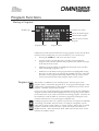
13.0 Default Screen
Unsaved
changes flag
T
Program
number and
name
Owner Lock
Output band
curves
On powering up, the FDS-366T performs internal checks and sets up the audio
path before releasing the output mute relays. This takes a few seconds. During
this time the operating software version will briefly be displayed. When the
FDS-366T is fully powered up the 'default' screen is shown, this gives a
representation of the current state of the unit.
If Lock Out mode in the Utilities is "On", the default screen will be replaced by
the standard BSS logo or one of the users choice, see the section on loading
custom logos for more information on personalising your Omnidrive.
The main area of the display contains the output band curves. Each band curve
represents the frequency response of the high and pass crossover rolloffs, in
addition to any equalisation filters that have been used (and are not hidden).
- 39 -
FDS-366T
14.0 Quick Start Guide
i
This section describes how to get started using the FDS-366T Omnidrive. If
you are unsure about how to use this product please take the time to study
this manual before attempting to deploy the unit in earnest. The FDS-366T is
a very capable device and as such, knowledge of both audio sound systems
and the way that the Omnidrive integrates with them is required, especially
to achieve the best results. If you are familiar with the concepts of setting up
a system then following this Quick Start guide should enable you to access
the facilities of the Omnidrive quickly and easily.
Further information is available in the relevant sections of the manual for
clarification of the functionality described below, plus there are many other
higher level features that can be employed and these are described
elsewhere.
Connecting up
Audio connections
The audio connections should be made before powering the unit. All inputs
and outputs are electronically balanced, with Pin 2 'hot' signal (+ve), please
ensure that your system wiring conforms to the correct specification.
Outputs from your source equipment, e.g. mixer, should be connected to the
FDS-366T inputs using inputs A&B for stereo analogue sources or input A for
AES digital connection.
The output channels from the FDS-366T should be used to feed amplification
systems connected to the relative speakers for the particular bands that are to
be setup in the Omnidrive.
Do not put any audio through the unit at this time.
AC power connection
,
The FDS-366T has a universal voltage AC power input. Connect the FDS-366T
to AC power with the lead supplied. The unit will switch on automatically
(there is no separate on/off switch). The display should show the default
screen, with the current program (if selected), and overall system response
curves.
- 40 -
FDS-366T
Quick Start Guide
Getting going with
a preconfigured
program
T
•
Program recall
If the FDS-366T has already been configured with a suitable program, you
only need to use the recall mode to set the parameters to that program.
!
Be aware that different programs may contain inappropriate routings
and EQ/Limiter settings for your particular system so care should be
exercised when selecting the correct program.
Press RECALL. Turn the rotary encoder to select the required program by
number and name, and press RECALL again.
Programs marked with diamonds are ‘OEM’ programs and have usually been
designed to match specific sound systems. Programs marked with a padlock
symbol are 'Owner' programs. Either of these two types of locked programs
may only allow edting access of some of the units functions.
Some units will be locked to a specific program only, in this case most controls
will be disabled and the unit will be ready for use.
•
Recalling a program from a PC Card
To load programs from a PC card:
1
Push the card into the slot on the front panel of the FDS-366T.
2
Press RECALL.
3
Press 'v' on the navipad control to highlight "Int", and turn the encoder
to select "6Prg" (or "6All" for a full PC Card recall).
4
Press the '^' key to return to file selection, and turn the rotary encoder to
select the required program.
5
Push RECALL again to recall the program as the current setting.
5Prg and 5All are for the recall of FDS-355 programs which can be read by the
FDS-366T (refer to the PC Card chapter for more info).
Getting some output:
Having selected the appropriate program for the application of the Omnidrive
now it is time to apply some audio source material to the unit's inputs. By
default all the output mutes should be lit red, i.e. channels muted, so to hear
the signal unmute the outputs one by one checking that the sound output is
correct for the speaker system required. Adjust the trim levels as necessary to
acquire the correct volume balance.
A brief explanation of how to edit the Omnidrive's parameters follows on the
next page.
- 41 -
FDS-366T
Quick Start Guide
Setting up a system
The overall configuration of the FDS-366T is the first parameter that needs to
be set. Decide whether the unit needs to run as a stereo 3 way, mono up to 6
way or as a 3 channel 2 way device.
•
Configuration
The FDS-366T has 4 modes as starting points from which the unit can be
configured:
"Mono" - Mono 6-way
"LLMMHH" - Stereo 3-way (similar to FDS-355 routing)
"LMHLMH" - Stereo 3-way
"LHLHLH" - 3-channel 2-way
Access the Utilities menu from the default screen by pressing the ^ navipad
key, or press the Utils button. Scroll around the Utilities menu, if required, to
access the "Configuration" screen.
Turn the rotary encoder to select the option you wish to use.
NOTE: When the configuration is changed, the unit will prompt for
confirmation of the action. If the 'ENTER' key is pressed, then the mode will
change, and default values for that configuration will be restored. It is
advisable to do a 'Store' before changing configuration if you have edited a
program previously.
Note also that all audio output mutes are 'on' by default however, as these
mutes are the last function to be applied during the change it is possible that
some audio may be heard. It is still therefore recommended that volumes be
turned down when switching Configurations to avoid possible damage to
speaker systems.
Once the Configuration is chosen, the crossover points, individual band delays,
EQ, DEQ and limiter parameters can be set up.
•
Setting the crossover points
1
Select the band to be edited by pressing the output assign key on the
required channel.
2
Press the navipad ^/v keys until the first crossover ('Low' slope) screen
appears.
3
Select the filter shape from the available types with the rotary encoder.
Choose between Butterworth (Butt), Bessel (Bess), Linkwitz-Riley (L-R)
and NTM and between the various slope rates available.
4
Press the navipad ^ key to access the frequency/Xover point and
choose its frequency using the rotary encoder wheel.
5
The high slope and frequency screen is then accessed by pushing the ^
key.
•
Assigning Band delays
- 42 -
FDS-366T
Quick Start Guide
Use the navipad ^/v keys to select the delay screen. The delay is adjusted
using the rotary encoder.
Default settings for display and adjustment of delay is in meters (m), but can
be changed to milliseconds (ms), feet/inches (ft) or frames per second (fps)
using the "Delay Units" parameter in the Utilities.
Bands can also be linked so multiple outputs can be delayed as one using the
"Delay Link" facility.
•
Adding EQ
Use the navipad ^/v keys to move to the EQ screen. The EQ shape can be
edited first. The shape of the EQ can be selected from one of the following by
turning the rotary encoder:
High Shelf with 12dB slope (Hi12)
High Shelf with 6dB slope (Hi6)
Bell
Low Shelf with 6dB slope (Lo6)
Low Shelf with 12dB slope (Lo12)
Navigate around the other EQ parameters using the navipad to adjust:
-
Filter Frequency (kHz)
Cut/Boost (dB)
Filter Bandwidth (Oct) (bell EQ only)
Once an EQ has been set, press ^ again to assign a new EQ (if required).
•
Setting the limiters
There are several parameters associated with the limiters of the FDS-366T,
which allow you to:
-
Switch the limiter (On/Off)
Adjust the limiter threshold (Thr)
Adjust the attack & release times (Atk & Rel)
Adjust the brickwall limiter overshoot (Over)
The output meters are calibrated to the threshold, so the threshold value will
determine the reference of '0' on the meter at all times, even if the limiters
are off. The threshold is indicated in dBu, but can be changed to mV via the
Limiter Units screen in the Utilities.
•
Storing your settings
- 43 -
FDS-366T
Quick Start Guide
When you have set up the Omnidrive it is essential to store your settings so
that they can be recalled should the power be removed from the unit.
Press the STORE button to enter the store mode.
Select an unused program location from the list, the Omnidrive will move the
cursor to the naming area of the screen. Input an appropriate name for your
settings using the rotary encoder to change the characters and the navipad </>
keys to move along the naming area.
Having given your program a name press STORE again. The Omnidrive will
ask if you want to store the program with a lock to prevent accidental further
storing over this memory location. Select either "Locked" or "Unlocked" and
press STORE a final time to commit your settings to memory.
A locked program is denoted by the key symbol displayed next to the name of
the program.
This Quick Start Guide is only designed to get you up and running with the
FDS-366T Omnidrive's more obvious features. There are many more facilities
that can be implemented, including dynamic EQ, phase adjustment, polarity
reversal and gain, please refer to the 'Outputs' section of this manual for further
information. Also remember that EQ, gain and delay can be applied to the
input channels, see the 'Inputs' section for more information.
- 44 -
FDS-366T
15.0 Quick Reference - How to ...
Use delays for
driver alignment
The best way to do this is to have a good idea of the physical positions of the
voice coils of the drivers in the cabinet. If you do not know this, an estimate
can be made, but it may take a while longer.
For example consider a 3-way box; with a 12” direct radiator, a 2” horn with a
compression driver, and a 1” bullet.
The voice-coil furthest away from the front of the cabinet will be the 2” horn,
so the other two drivers will need delaying to compensate for the time it takes
the audio energy to reach the outer flare of the horn. This distance could be
300mm. Subtract from this the distance of the voice coil of the low driver (lets
say 120mm) and set that delay to the result (180mm). Do the same for the 1”
bullet, which will usually have a shorter distance from voice coil to front, and
hence need a longer delay.
Alternatively use the Alignment Assistant to aid this process with
measurements, see the Alignment Assistant section in the Utilities chapter of
this manual for more information.
Keep relative
delays while
delaying a group
Name a band
This is achieved by using the 'Delay Link' mode. Any bands can be linked so
that a delay applied acts to all the linked bands. This means that relative shifts
between cabinets can be made without upsetting driver alignments.
Select the output band to be linked, then use the navipad ^ key to cycle
through the screens until the Delay Link screen is shown. Turning the rotary
encoder will show all possible choices, which are determined by the bands
sourced from the same input. The graphic display will also show the bands
being linked.
The FDS-366T has a preset list of names you can select from which may suit
your system layout. For example, Output 1 can be renamed to Subs.
To do this:
•
Select Output 1 by pressing the appropriate output select button or by
pushing the rotary encoder to select Output 1.
•
Use the navipad v key to select the Name screen (if not already shown).
•
Turn the rotary encoder to select a relevant name for the output. The
name is automatically retained at the top of the display when a new
screen is selected.
- 45 -
FDS-366T
Quick Reference - How to ...
Make a band full
range
The 'Xover Adjust' must be changed from "Both" to "Edge" in the Utilities.
Pressing UTILS while in a crossover edit screen will select 'Xover Adjust'.
1
2
3
4
5
Add EQ for
Constant Directivity
horns
Constant Directivity horns often require additional equalisation in order to
extend their frequency response. In most cases, this is a fairly simple EQ,
requiring only a gentle slope (6dB per octave) high-pass shelving filter.
To add CD EQ:
1
2
3
4
5
6
7
Load custom logos
Select the band to be edited by pushing the output assign buttons.
Use the navipad ^/v keys to cycle to the Xover frequency for the
lower band edge ("Low Freq").
Turn the rotary encoder anti-clockwise until the display reads
"OUT", the graphic display should show the lower edge as a
horizontal line, with no roll-off.
Pressing the navipad ^ key twice will access the upper edge
Xover frequency screen ("High Freq").
Turn the rotary encoder clockwise until the display reads "OUT",
and the band is shown as completely flat, i.e. displayed as a
continuous horizontal line across the display.
Select the band to be equalised by pressing the output assign
button or by pushing the rotary encoder to select the channel
Press the navipad ^/v keys until you reach a free EQ.
Select the 'shape' icon at the top of the screen and select a 6dB,
Hi Pass filter by turning the rotary encoder until the graphic
shown left is displayed.
Push the navipad < key to access the EQ frequency.
Adjust the frequency by turning the rotary encoder to about 2kHz
(check with your manufacturer for detailed information about
frequency and boost requirements for a system).
Push the navipad > key to access the EQ cut/boost, and turn the
rotary encoder to give a boost of about 6dB.
The frequency and boost values may need slight adjustment to
give the best results.
Custom logos can be loaded into the FDS-366T using the 366Load.exe loader
program (available from our web site, www.bss.co.uk).
•
These logos must be in .GIF 87a (non-interlaced) format.
•
The size of the FDS-366T screen is 128x56 pixels, and 2 colours.
•
Logos should be drawn with a white tool on a black background.
- 46 -
FDS-366T
Programming
functions
in depth
- 47 -
FDS-366T
16.0 Program Functions
The FDS-366T has 60 internal program memories which should be plenty of
storage space for most applications. However it is always good practice to
back up your programming work and this can be achieved in several ways.
Programs can be saved to a PC card (refer to the next chapter for more
information on the use of PC cards) or 'dumped' via MIDI into either another
FDS-366T or a computer/midi data storage medium for later recall.
Storing and Recalling a program can be done at any time using the STORE
and RECALL keys on the left hand side of the LCD, unless Backup and Swap
has been turned on (see more about this facility in the 'Utilities' section).
NOTE: If the unit is prompting for confirmation of an action at any time, the
STORE/ENTER key is often used to confirm the action, pressing it at these
times will not access the STORE facility.
Recalling a
Program
Press the RECALL key to access the Recall screen.
The rotary encoder selects the program number to recall (when highlighted), or
selects the internal memory or PC card to recall (when highlighted).
The ^/v keys are used to toggle between Program number and recall type.
The FDS-366T is able to recall both FDS-355 and FDS-366T file types,
although FDS-355 programs are converted to suit the new layout and range of
the FDS-366T parameters.
Int
Recall programs from the units internal memories.
Prg
Recalls the currently selected program from a PC card in the slot at the front
of the unit (with a FDS-355 file format).
All
Recalls all program data from a PC card in the slot at the front of the unit
(with FDS-355 file formats).
Prg
Recalls the currently selected program from a PC card in the slot at the front
of the unit (with a FDS-366T file format).
All
Recalls all program data from a PC card in the slot at the front of the unit
(with FDS-366T file formats).
When the program you wish to recall has been selected, push the RECALL key
again to recall the program. The unit will display a message showing that data
is being recalled, and will then display the default screen once the recall is
complete.
To exit from the recall screen without recalling a program, press any of the
select buttons other than the navipad.
- 48 -
FDS-366T
Program Functions
Storing a Program
STORE type
Program Lock status
Owner locked Program
OEM locked Program
OEM & Owner locked
Program
Program number
Program Name
Familiarise yourself with the method for storing programs as this must be done
to memorise any editing that you may have done to your system set up.
Program lock
•
Pressing the STORE key will access the Store screen.
•
Use the ^/v keys (or push the rotary encoder) to move along the
program name, and also between the program name and the store type
at the top left of the screen.
•
While the program number is highlighted, turning the rotary encoder
will cycle through programs 1-60.
•
While each of the letters in the program name are highlighted, turning
the rotary encoder will cycle through all available characters. Note that
the letters in the program name being edited (at the top of the screen)
are more spaced out than other program names on the screen...
This facility is available for each stored program. The last space in the
program name is reserved for program lock. If a program name displays a key
symbol at the right hand side, a new program, or edited version of the current
program, cannot be stored in this location.
If you try to store a program in place of a locked program, the unit will display
"Program Locked!", but will then highlight the key icon, giving you the option
to turn off the lock if you wish to overwrite the existing program. The lock can
be turned off in order to delete or overwrite a program by turning the rotary
encoder anticlockwise or by pressing the navipad 'v' key.
Locking a program in this way is purely to protect the user against accidentally
overwriting a stored file. The lock status can easily be changed by anyone
unless the program is either 'OEM' or 'Owner' locked. These types of locked
programs cannot be saved over unless a particular method is used to first
disable the locks. More information about 'OEM' and 'Owner' locks can be
found in the Utilities section.
- 49 -
FDS-366T
Program Functions
Store Type
There are 3 ways in which data can be stored, and these are indicated by the
store type message at the top of the display. To highlight the Store type
message, use the navipad 'v' key while a program number is highlighted. Once
highlighted, turn the rotary encoder to select the type of store you wish to use.
INT
This stores the program in the internal memory of the unit.
Prg
This stores the currently selected program to a PC card (if inserted) in the slot
at the front of the unit (in a 366T file format).
All
This stores all program data to a PC card (if inserted) in the slot at the front of
the unit (in a 366T file format).
The Program Lock can be applied to a program stored using any of these 3
methods.
NOTE: The edit flag ('*') appears when there are unsaved changes to a
program, compared to the initial status of the last recalled/stored program
(Internal memory only). When a program is stored to internal memory, the edit
flag will disappear.
If a program is stored to a PC card, then the flag will NOT disappear, since
there are differences between the last recalled/stored program (Internal), and
the current program.
Store Lock
Once the program name has been entered, the store type selected, and the
Program lock status cleared, pressing the STORE key again will prompt the
message "Store Locked?", asking whether the program should be stored with a
Program lock. Use the rotary encoder to turn the Lock on or off ("Locked?" or
"Unlocked?"). Once the Lock status is set, push the STORE key a final time to
commit the program to memory (or PC storage). The display will now default
back to the screen displayed before the STORE facility was accessed.
To exit from the store screen without storing a program, press the 'RECALL'
button.
- 50 -
FDS-366T
Program Functions
Delete Program
To delete a program press the UTILS button and scroll through the
options until the screen on the left is displayed.
To enter the Delete Program mode, press either > or turn the encoder
clockwise, this will change the screen to:
Choose the program to be deleted using the < and > keys or rotary
control.
Press ENTER to delete the program.
Pressing the ^/v keys at any time will exit the Delete Program mode.
Note:
Program locked (key symbol) and Owner locked (padlock symbol)
programs can both be deleted using Delete Program. OEM locked
(diamond symbol) programs can also be deleted using Delete Program
unless the Delete Program option was locked in the Utilities during the
OEM lock process. In this case the OEM program cannot be deleted if
it is the currently active program but, can still be deleted if another
program is selected.
To totally secure the unit with OEM programs both the Delete Program
and Configuration parameters must be locked on every program. If this
is not done then a user could create a new unlocked program by
changing the Configuration and this would then give access to Delete
Program again.
- 51 -
FDS-366T
17.0 PC Card Usage
Card types
Compatible Cards
Storage life
The program memories of the FDS-366T Omnidrive can be saved to PC cards
for further storage, safety backup and portability between systems. Note that
the PC card only inserts up to about a third of its length into the front panel
slot. Do not try to force the card further in as this could cause damage to the
unit. Also it is recommended not to leave unused cards in the slot as they
could become damaged if the unit is knocked from the front.
The PC Card socket on the front of the unit is designed to use PCMCIA type 2
memory cards of between 256kbyte and 2Mbyte storage capacity. The Smart
Card interface requires 68pin compatible SRAM memory cards. Attribute
memory is not required and is not used. 256K, 512K, 1MB, 2MB cards can be
used, however probably the most appropriate card size for the FDS-366T is the
256K card which can hold approximately 14 complete setup (CAL or PAL)
files.
Battery life varies with manufacturer and memory size and should be checked
with the card supplier.
Rechargeable cards are also available. These cards should periodically be left
in the card slot of an FDS-366T for a few hours to recharge. Expected battery
life for rechargeable cards when not plugged into a unit is about one year, but
should always be checked with the card supplier.
PC Card format
The PC Card filing system on the FDS-366T uses a ‘pseudo-floppy’ format. This
filing system conforms to the PC CARD standard although it does not format
Card Information Structure (CIS) information.
Formatting a Card on the FDS-366T writes a standard PC DOS format to the
card beginning at byte 0 as the first byte on a disc. The format writes a DOS
boot sector with basic format data but does not write boot software.
This is followed by a single File Allocation Table (FAT) starting at byte 200H.
The root directory is written with one entry, a sub-directory called BSSDATA.
All data files used by the unit are stored in the BSSDATA sub-directory as there
are limits to the number of files that can be stored in the root directory.
The file types that are recognised by the FDS-366T have different file
extensions as follows.
"6Prg"
FDS-366T Program data
*.PPG
"6All"
FDS-366T All data
*.PAL
"5Prg"
"5All"
FDS-355 Program data
FDS-355 All data
*.CPG
*.CAL
The file sizes are variable, and change with the number of EQs used, and
number of programs.
- 52 -
FDS-366T
PC Card Usage
Computer
compatibility
:
FDS-355
compatibility
BSS has tested and developed the card filing system using an IBM compatible
PC card reader and a range of palm-top computers, but cannot guarantee that
the cards can be read by any particular piece of computer equipment.
To transfer files to and from an external computer note the following:
•
Format the card on the computer.
•
Write a sub-directory called BSSDATA into the root directory
immediately after formatting the card. All files used by the FDS-366T,
FDS-388 and FPC-900 remote are stored in the BSSDATA sub directory.
The FDS-366T Omnidrive is capable of reading the programs from the older
FDS-355 five channel Omnidrive with a few differences, shown below.
In RECALL mode the FDS-355 programs are listed as "5Prg" or "5All". "5Prg" is
used to load individual FDS-355 programs and "5All" loads a set of FDS-355
programs overwriting all the data in the FDS-366T in the process.
When FDS-355 programs are loaded into the FDS-366T, the five FDS-355
channels become the top five channels on the 366, i.e. outputs 2-6. This is
intended to allow most stereo FDS-355 programs with a mono sub bass to
convert to a stereo sub bass pair. After the conversions are done, channel 2
(which was previously channel 1 on the FDS-355) is copied into the new
channel 1 on the FDS-366T, i.e. channels 1 & 2 become identical.
Gain, limiter threshold and eq cut/boost dB values are all converted to the
new finer steps/incremental values on the FDS-366T. For example the eq cut/
boost values are changed from 0.5dB steps to 0.2dB steps so there may be
0.1dB changes in the values after conversion, e.g. 2.5dB becomes 2.4dB while
2.0dB would stay the same.
If the limiter was "Off" in the FDS-355 program, it stays off. If it was "On"
then the Attack and Release parameters in the FDS-366T are set to "Med"
(medium). If the Limiter Attack on the FDS-355 was set to "Fast" then the
Over (overshoot) value is set to 6dB, otherwise it will be set to 12dB.
Dynamic EQs are set to defaults, i.e. with no cut/boost applied.
- 53 -
FDS-366T
18.0 Utilities
Introduction
The Utilities contain settings for the FDS-366T that are of a more general
operational nature, rather than particularly related to the individual function of
the input and output channels.
Pressing the UTILS button or pushing the navipad '^' key while viewing the
'default' screen will display the Utilities menu. The '^' and 'v' keys are then
used to move along the Utilities path, which starts at the bottom of the list and
works upwards, and the rotary encoder is used to change the selected
parameter. If confirmation of an action is required, the STORE/ENTER key
should be pressed.
Utilities with ">" next to their names have further screens associated with them.
Press '>' on the navipad to access the extra parameters.
Note: The '96kHz' indicator light under the Utils button is purely to display
the units sample rate for the AtoD and DtoA conversion of the audio.
The Utilities can be regarded in several functional groups:
•
Overall configuration of the input/output routing
1.
Configuration
2.
Stereo Link
3.
Sum Type
•
Operational alignments & adjustments
4.
Xover (Crossover) Adjust
5.
Phase Comp(ensation)
6.
Alignment Assistant
7.
Delay Corrn (Correction)
8.
Temperature
•
Display units
9.
Limit Units
10. Delay Units
•
Screen adjustment
11. Brightness
12. Contrast
•
Security locks
13. Lock Out
14. Owner Lock
15. OEM Lock
•
Connector modes
16. Input A/AES
17. Serial Port
•
MIDI functions
18.
MIDI Mode
19.
MIDI Channel
20.
MIDI Dump (also a program function)
•
Program functions
21. Store Gain Trims
22. Backup & Swap
23. Delete Program
24. Format Card
- 54 -
FDS-366T
Utilities - Configuration & Routing
1.
Configuration
"Mono", "LMHLMH", "LLMMHH" or "LHLHLH"
Configuration defines the general operating mode for the FDS-366T; either
Mono, Dual/Stereo 2-Way or Stereo 3-way. The rotary encoder is used to
select the desired configuration.
2.
Stereo Link
•
"Mono" mode assigns all outputs from input A.
•
Stereo "LMHLMH" mode routes input A to outputs 1, 2 & 3 and input B
to outputs 4, 5 & 6.
•
Stereo "LLMMHH" mode routes input A to outputs 1, 3 & 5 and input B
to outputs 2, 4 & 6. (Similar to the FDS-355)
•
Three way "LHLHLH" will route inputs A, B & C to 1&2, 3&4, and 5&6
respectively to drive three 2-way speakers. e.g left, centre, right or 3 biamped monitors.
"On" or "Off"
This mode selects whether parameters will be adjusted together, or
independently on each stereo pair of channels.
Turning the rotary encoder clockwise selects Stereo Link "On", and
anticlockwise selects "Off".
If a MONO configuration is chosen then this parameter is set to "Off" and is
unchangeable.
3.
Sum Type
"A+B Post EQ", "A+B+C Post", "A+B Pre EQ" or "A+B+C Pre"
Determines what signals are mixed together for the Sum channel. The mono
sum is often used for sub-bass drive and can be derived from either inputs A&B
or A, B & C (useful for LCR systems particularly).
The sum options are:
•
A+B Post EQ
Input A plus Input B (with 6dB of attenuation), with input equalisation.
•
A+B+C Post EQ
Input A plus Input B plus input C (with 9.5dB of attenuation), with input
equalisation.
•
A+B Pre EQ
Input A plus Input B (with 6dB of attenuation), without input
equalisation.
•
A+B+C Pre EQ
Input A plus Input B plus input C (with 9.5dB of attenuation), without
input equalisation.
When selecting the signal source in the Output channels, it is this sum which
becomes one of the source options.
- 55 -
FDS-366T
Utilities - Crossover Adjustment/Phase Comp
4.
Xover Adjust
"Both" or "Edge"
The Xover Adjust determines how crossover points are adjusted relative to the
corresponding edge of the adjacent band. The following options may be
selected:
BOTH
When set to BOTH, both the upper band edge of the lower band and the lower
band edge of the upper band are adjusted as a pair. This means that only one
filter adjustment is required to set a crossover point, and the graphic display
shows both edges moving together.
NOTE: You can select either band in order to adjust the crossover - the lower
band or upper band - and either adjustment will move both band edges
together, updating the data for the other band.
or
EDGE
When set to Edge mode, each band edge is adjustable independently. This
allows the possibility to create band overlaps at the crossover point.
or
5.
Phase Comp
"On" or "Defeat"
By default the FDS-366T is set up to analyse and apply phase compensation to
networks using identical crossover shapes across three bands or more. This is
generally desirable but, there are certain circumstances when it may be
necessary to defeat this feature, such as when using split systems, some
monitor applications and side or under fills.
Further information regarding the implementation of phase compensation can
be found in the 'Crossover Shapes and Frequencies' section of this manual.
- 56 -
FDS-366T
Utilities - Alignment Assistant
6.
Alignment
Assistant
The Alignment Assistant is an advanced loudspeaker measurement function
built-in to the FDS-366T for directly measuring the delay and phase
relationships between drivers (using a measurement microphone), and
automatically adjusting the settings to accommodate these. The Alignment
Assistant has the ability to ‘see’ past the crossover filters, and is thus able to
compensate for the drivers and enclosures themselves, leaving the crossover to
do exactly what it was intended to do, and present a precisely aligned acoustic
wavefront. The Alignment Assistant can measure and compensate for:
•
Physical alignment of drivers within an enclosure
•
Driver or enclosure phase anomalies near the crossover point
•
Relative distance correction of arrayed boxes
Note that Alignment Assistant will not alter the phase response of the selected
crossover alignment. This will be preserved by the Phase Compensation
feature, dependent on the Phase Compensation Defeat setting in the Utilities.
Method
Alignment Assistant uses a special stimulus signal that is sent to the outputs of
the FDS-366T during measurement. Each band output is stimulated in turn (via
the normal crossover filtering and equalisation). A measurement microphone
plugged into the C input of the FDS-366T picks up the stimulus reproduced by
the driver under test, and records the result for analysis. The special nature of
the stimulus signal allows not only the delay (distance) from driver to
microphone to be established, but also the impulse response of the driver/
enclosure, from which phase details can be calculated.
Once all the bands have been measured, the delay and phase results are stored
and used to determine the band delays to be applied to make the wavefront
from the system coherent between drivers and between cabinets. Various
options allow the measurement to be biased towards driver alignment within a
cabinet, cabinet alignment, polarity correction, or a combination of these.
Microphone
placement and
connection
The microphone must be placed far enough away from the loudspeakers so
that the vertical placement of drivers does not give rise to differential delays
which the listener will not normally be subjected to. It must be close enough
that a reasonable level of acoustic energy of the stimulus is achieved and
thereby ensuring that there is good signal-to-noise ratio. A good placement
would be a forward listener position.
If an array of two or more cabinets are to be aligned, then the microphone
should be placed centrally between the cabinets. If the drivers within a cabinet
are to be aligned then better signal-to-noise conditions will exist closer to the
cabinet. The microphone should then be optimally placed on the central axis
of the cabinet at a distance of perhaps 3 metres (10 feet) or so. Care should be
taken to place the microphone away from acoustically reflective surfaces such
as walls, pillars etc.
The microphone must be plugged into Input C. When the automated
measurement process is running, it is important that the microphone is not
moved. A microphone stand is highly recommended. Although the system is
quite tolerant of noise, It makes sense to keep the environment as quiet as
possible.
- 57 -
FDS-366T
Utilities - Alignment Assistant
Procedure
The alignment assistant takes you step-by-step through the various stages of
the process starting with the "SELECT OPTIONS" screen.
Determine which parameters are to be measured and adjusted.
•
Output Delays are used for correcting for discrepancies in distance or
phase between adjacent drivers in a cabinet or stack.
•
Input Delays are used for aligning cabinets with one another.
•
Polarities will correct driver polarities.
Use the Navipad ^ and v to move to the menu item you wish to adjust, then
use < and > to change the selection between "Yes" and "No".
Once you are happy with the selections, press the ENTER button to continue
the assistant.
Selecting bands to
measure
You do not have to measure all bands at once; you can decide to exclude
some bands from a measurement session.
Use the front panel mute buttons to determine which bands are to be included
in the measurement session. Muted bands will not be measured and will not
have their parameters altered. Initially no bands will be selected. At least one
band must be unmuted for the Alignment Assistant to work.
Once you are happy with the selections, press the ENTER button to start the
measurement process.
! If all the outputs are muted then the Omnidrive will warn that there are not
enough outputs to start the process.
The measurement system is tolerant of a reasonably wide range of stimulus
levels received at the microphone and is fairly tolerant of extraneous noise
also. However, optimal measurement accuracy will be obtained with
reasonably high levels of stimulus. The unit allows this level to be set
subjectively.
The stimulus, which sounds similar to pink noise, will start at a low level. Use
the rotary encoder to adjust the level of the stimulus to a reasonably high
sound pressure level which is still comfortable to listen to (or wear ear
defenders!).
As the signal level is increased, you will see the input C bargraph meter
beginning to indicate that the microphone is receiving the signal. The unit will
expect to see a certain minimum signal level before allowing you to continue.
You should avoid setting the level so high as to cause any outputs to limit or
clip.
- 58 -
FDS-366T
Utilities - Alignment Assistant
Adjusting the
stimulus level
As you increase the stimulus level, the microphone amplifier in the FDS-366T
will automatically adjust it’s gain to try to obtain a good level. You may
therefore not see the input C bargraph value changing once it gets close to fullscale.
If the input level is reasonable and the outputs are not limiting or clipping then
start the automated measurement phase by pressing the ENTER button.
p
Warning: As the automated part of the measurement process
continues, similar SPL(Sound Pressure Levels) stimulus signal
levels to those set above will be output intermittently. Care must
be taken to ensure that nobody will be subjected to potentially
hearing-impairing SPLs.
After measuring each band, the impulse response of the band will be shown
graphically on the screen. This may be useful for checking that the Alignment
Assistant has captured a sensible measurement rather than noise, etc.
Press ENTER to continue with the next band.
If this warning is encountered this is because the delay parameters on the
output channels that the Alignment Assistant is trying to measure are either
'OEM' or 'Owner' locked. To prevent this, escape from the Alignment
Assistant by pressing the RECALL button, go to the appropriate lock in the
Utilities and deactivate the locks that have been set on the delay parameters on
the output channels. Now restart the Alignment Assistant procedure which
should now work without this warning appearing.
The not enough level warning may also be encountered at this stage as each
band may need tuning separately.
- 59 -
FDS-366T
Utilities - Alignment Assistant
Notes
1.
Which parameters get overwritten?
Some parameters get overwritten by running Alignment Assistant.
If you have valuable settings in place it is recommended that you
save the current setup to a new program location before
activating Alignment Assistant.
Depending on what options you activate when starting Alignment
Assistant the following parameters get overwritten:
•
Output Delays
•
Input Delays
•
Polarities
Any bands that are omitted from alignment will have their settings
preserved.
2.
Linking
Stereo linking and delay linking have no effect on Alignment
Assistant. Every band that is selected for alignment will have its
parameters individually measured and set.
3.
Polarity in 2nd & 3rd order systems
Alignment Assistant will not try to evaluate the correct polarity for
crossover alignments which require polarity inversion, such as
2nd order and some 3rd order alignments. If the polarity option is
enabled, the polarity of the measured bands will be corrected on
an individual basis. If you wish to make corrections for crossover
alignments which require other polarity settings then these should
be applied manually.
4.
Effects of band EQ & dynamic EQ
Alignment assistant will accurately take into account the effects of
crossover settings, but will not account for any equalisation you
have put in place on the output bands.
It is assumed that any output equalisation has been applied
deliberately and that you require the phase effects that the
equalisation will produce. If not, then more accurate results will
be obtained if input equalisation is used instead of output
equalisation.
The same applies for Dynamic Equalisation, although more so,
since the phase relationship will change dynamically depending
on signal level, causing Alignment Assistant to produce results
which are only correct at the level of the stimulus.
- 60 -
FDS-366T
Utilities - Alignment Assistant
5.
Accuracy
It is difficult to predict accuracy but, under the correct conditions
the Alignment Assistant will be more than adequate for aligning
drivers to within a few degrees.
Very low frequency bands are often aligned less accurately in
terms of time, because of the poor stimulus bandwidth, but will
be more than adequate in terms of phase angle. Note also that
very low frequency bands can easily be phase shifted by DC
block filtering, both within the FDS-366T and in external
equipment, causing additional time shifts to be correctly aligned
out.
6.
C input - care needed with feedback
When using input C in your system care should be taken when
Alignment Assistant finishes, since the routing of input C will
revert back to feeding outputs. Although the gain will be very
much lower (because the microphone amplifier is defeated), this
could under some circumstances cause feedback to the
microphone.
7.
Exiting the Alignment Assistant
If at any time during the process you wish to escape back to
normal operation, press the RECALL button.
8.
Maximum distance/delay
Alignment Assistant has an upper limit on the maximum delay
time that may be measured of approximately 75ms (23 metres or
75 feet). If the distance between the driver and the microphone
causes a delay any greater than this, erroneous readings will
result.
9.
Microphone type
The choice of measurement microphone is not critical, although a
high quality capacitor microphone with a flat frequency/phase
response will give more accurate results.
If the microphone is phantom powered, it must be capable of
operating at a phantom voltage of at least 15V.
We recommend the BSS FPC900-MIC for this application.
- 61 -
FDS-366T
Utilities - Adjustments, Units and Screen
7.
Delay Corrn
(Correction)
"Off", "Manual" or "MIDI"
Corrects the implementation of delay in the unit to compensate for ambient
temperature. This facility works in tandem with the Temperature utility.
With Delay Corrn (correction) set to 'Off', the default temperature is set to
20°C.
Setting Delay Corrn to "Manual" allows a user defined value to be entered,
from -20°C to 50°C, in 1°C increments.
If Delay Corrn is set to "MIDI", then the temperature value can be taken from
a temperature probe connected to a FDS-388. If the 366 is used with a single
388, then the 366 MIDI input should be attached to the MIDI output of the
388. The 388 should be set to "MIDI:XMIT MET".
8.
Temperature
o
o
-20 C to +50 C
Sets the ambient temperature manually if Delay Corrn is set to 'Manual'.
9.
Limit units
"dBu" or "mV"
The limit units screen allows the units of limiter threshold to be changed
between dBu and mV, depending on your amplifier specification.
10.
Delay units
"ms", "ft", "m", 24fps", "25fps" or "30fps"
This selects the units used for displaying and adjusting delays.
•
ms represents milliseconds
•
ft represents feet (and inches - for short delays)
•
m represents metres.
•
24, 25 and 30fps represent delays using 24, 25 and 30 frames per
second respectively - for syncing to video and film.
Note that for longer delays, the resolution of the rotary encoder is reduced to
match the number of decimal places displayed. Short delays will adjust in
approximately 11us increments, whilst longer delays will adjust in 100us
increments.
11.
Brightness
"High" or " Low"
Change the brightness of the LCD display's backlight. Select between High or
Low for different ambient light conditions.
12.
Contrast
Change the contrast of the LCD display. A "/" character will rotate to show that
the value is being changed. Adjust until the screen display is the most easily
readable.
- 62 -
FDS-366T
Utilities - Security Lock Outs
Any changes made to an audio system have the potential to be damaging,
even if only accidentally made. For this reason several different security
systems are built in to the FDS-366T to protect the system.
The security levels offered by the FDS-366T enable the various functional
aspects of the Omnidrive to be secured away from accidental or malicious
adjustment. Some locks are quite easy to defeat, while others deliver in depth
protection for preconfigured set ups at parameter level and are accessed by
passwords.
13.
Lock out
"On" or "Off"
Lock Out mode prevents access to editing functions on the input and output
channels. Since this utility is not password-protected, Lock Out can still be
accessed and turned off. This mode is intended only as a precaution against
accidental adjustments, and not as a tamper-proof security lock.
When Lock Out is set to "On", no variables can be changed except for the
display Brightnesss and Contrast and, of course, the Lock Out itself. The
screen will display either the unit's BSS logo or any custom logo that has been
loaded, (see the Quick Reference section for more details on how to load your
own custom logo). Navigation around the various screens to look at the
parameter values is possible but only the front panel gain trims and mutes are
adjustable.
! Locking the unit in this way is only to protect the Omnidrive against other
users changing the system setup accidentally or against unauthorised people
intentionally changing the system. This status can be changed by anyone who
knows how to operate the FDS-366T.
14.
Owner lock
"Off" or "Active"
The Owner Lock mode gives the programmer the ability to hide selected
parameters from other users' view and prevent those parameters from being
tampered with.
A password is entered by the programmer to protect the integrity of the locked
parameters, and this password is necessary to subsequently gain access to the
'Owner' locked parameters and to the parameter locking mechanisms.
The end user may then use the locked 'Owner' program as a basis for
operating a system, and only make further modifications to the setup to an
extent completely controlled by the program designer.
Owner locked programs are denoted by the padlock symbol, shown left, next
to either a program name or next to any parameters that have been Owner
locked.
It is advisable to edit a program to the desired level before starting the locking
process as further changes to parameter values cannot be made during the
locking process.
Note that 'OEM' locked parameters cannot be unlocked or viewed with the
Owner Lock.
- 63 -
FDS-366T
Utilities - Security Lock Outs - Owner lock
Setting up 'Owner'
Locks
1.
To activate the Owner Lock go to the Utilities, select "Owner Lock"
and turn the rotary encoder clockwise.
2.
Enter the default password, which is "OMNI" for Owner Lock, by
turning the rotary encoder to change the displayed character, and then
either pressing the navipad > key or pushing the rotary encoder to move
along the password. The use of a default password is to prevent
accidental or malicious setting of lock flags.
3.
Press ENTER to enter the default password.
4.
The "Lock Setup" screen is briefly displayed indicating to press the
ENTER key when you have finished setting up the locks.
5.
After this screen the "Lock all?" screen is displayed. This facility allows
the locking of all parameters (that are saved as part of a program)
immediately and is a good starting point if you want to unlock only
particular parameters. Equally, if you wish to selectively lock only
certain parameters leave "Lock all?" off. Press any button other than
ENTER to move into the programming screens.
6.
The screens from here on can be moved around in the usual manner,
but turning the rotary encoder will now toggle Owner Lock on/off for the
current parameter (shown by a padlock icon in place of the current
value) instead of changing any values. Be sure to have set any program
parameter values to those desired before entering the lock setup mode.
The word "Own" in the top left of the screen denotes that this is Owner
Lock mode and prompts you to press ENTER when finished setting the
locks.
7.
At the 'end' of the used EQs screen, there is an option to '"Lock Unused
EQs". This option prevents any user without the correct password from
entering any further EQs onto that channel.
8.
Once the required parameters have been locked out, the ENTER key
should be pressed again - prompting for the user password to be
entered. At this point it is possible to change the existing default
password to one of your choice - particularly recommended if the unit is
to be hired out as the default password is the same on all FDS-366Ts.
Note that the password is alphabetical only.
9.
Press the ENTER key a final time to exit Owner Lock setup mode,
confirming the lock selections.
- 64 -
FDS-366T
Utilities - Security Lock Outs - Owner lock
Storing Owner
Programs
To store a program as an 'Owner' program, the unit must be in Owner Lock
setup mode when the program is stored, otherwise the stored program will not
be identified as an Owner program in the program list. So as soon as the last
set of locks have been applied and STORE/ENTER has been pressed to confirm
the selection press STORE again and save the program.
Adding further
locks
Further locked parameters can be set up by first turning Owner Lock from
"Active" to "Off" in the Utilities. To do this follow the procedure as above for
entering the password and type in the user password, this time upon pressing
ENTER you will be returned to the Utilities and the Owner Lock will now be
"Off". Switch the Owner Lock back into set up mode by restarting the process
as before, now using the default password. This time your previously locked
parameters will still have the locked icons next to them and you can either
change these settings or add new locks to further parameters.
In the RECALL and STORE screens the padlock symbol will be displayed next
to any program that has had Owner locks applied to it. If the program is also
locked the key symbol will not be shown unless you attempt to store over the
program. In this case the "Program Locked!" warning will be shown and the
cursor will move to the padlock icon. Turning this off with the navipad 'v' key
will reveal the key symbol, turn this off too in oder to store an edit over the
existing program.
! The Owner locks can only be changed by someone who knows the Owner
Lock password. BE WARNED THAT IT IS IMPOSSIBLE TO UNLOCK A
PROGRAM WHERE THE PASSWORD HAS BEEN FORGOTTEN.
- 65 -
FDS-366T
Utilities - Security Lock Outs - OEM lock
15.
OEM Lock
"Off or "Active"
The OEM Lock mode gives the user the ability to hide selected parameters
from other users' view and prevent those parameters from being tampered
with. OEM Lock is the highest level of programmable security available to
the FDS-366T.
A password is entered by the engineer to protect the integrity of the locked
parameters, and this password is necessary to subsequently gain access to the
OEM locked parameters and to the parameter locking mechanisms.
The end user may then use the locked 'OEM 'program as a basis for operating
a system, and make further modifications to the setup, to an extent completely
controlled by the designer.
Setting up 'OEM' Locks:
1.
To activate the OEM Lock go to the Utilities, select "OEM Lock"
and turn the rotary encoder clockwise.
2.
Enter the default password, which is "BSS" for OEM Lock, by
turning the rotary encoder to change the displayed character, and
then either pressing the navipad > key or pushing the rotary
encoder to move along the password. The use of a default
password is to prevent accidental or malicious setting of lock
flags.
Press STORE/ENTER to enter the default password.
3.
4.
The "Lock Setup" screen is briefly displayed indicating to press the
STORE/ENTER key when you have finished setting up the locks.
5.
After this screen the "Lock all?" screen is displayed. This facility
allows the locking of all parameters (that are saved as part of a
program) immediately and is a good starting point if you want to
unlock only particular parameters. Equally, if you wish to
selectively lock only certain parameters leave "Lock all?" off.
6.
The screens from here on can be moved around in the usual
manner, but turning the rotary encoder will now toggle OEM Lock
on/off for the current parameter (shown by a diamond icon in
place of the current value). The word "OEM" in the top left of the
screen denotes that this is OEM Lock mode and the bottom line
prompts you to press STORE/ENTER when you have finished
setting the locks.
7.
At the 'end' of the used EQs screen, there is an option to '"Lock
Unused EQs". This option prevents any user without the correct
password from entering any further EQs onto that channel.
8.
Once the required parameters have been locked out, the STORE/
- 66 -
FDS-366T
Utilities - Security Lock Outs - OEM Lock
ENTER key should be pressed again - prompting for the user
password to be entered. At this point it is possible to change the
existing default password to one of your choice - particularly
recommended if the unit is to be hired out as the default
password is the same on all FDS-366Ts. Note that the password
is alphabetical only.
9.
Storing OEM
Programs
Press the STORE/ENTER key a final time to exit OEM Lock setup
mode, confirming the lock selections.
To store a program as an 'OEM' program, the unit must be in OEM Lock setup
mode when the program is stored, otherwise the stored program will not be
identified as an OEM program in the program list. So as soon as the last set of
locks have been applied and STORE/ENTER has been pressed to confirm the
selection press STORE again and save the program.
When OEM programs are stored, they are automatically program-locked, and
identified in the program list by a diamond. The OEM program lock status
cannot be undone by the program lock utility, but an OEM program may be
overwritten by another OEM program with the same OEM password.
For example, recalled OEM program 1 cannot immediately overwrite program
1, even if the same OEM password is used, and the message "Program
Locked!" will appear. The OEM Lock must first be turned off, and then turned
back on again (using the same password). Now if the program is stored over
program 1, the STORE facility will allow the program to be overwritten.
! The Owner lock mode can only be changed by someone who knows the
Owner Lock password. BE WARNED THAT IT IS IMPOSSIBLE TO UNLOCK A
PROGRAM WHERE THE PASSWORD HAS BEEN FORGOTTEN.
Adding further
locks
Further locked parameters can be set up by first turning OEM Lock from
"Active" to "Off" in the Utilities. To do this follow the procedure as above for
entering the password and enter the user password, this time upon pressing
ENTER you will be returned to the Utilities and the OEM Lock will now be
"Off". Switch the OEM Lock back into set up mode by restarting the process as
before, now using the default password. This time your previously locked
parameters will still have the locked icons next to them and you can either
change these settings or add new locks to further parameters.
- 67 -
FDS-366T
Utilities - Security Lock Outs - Notes
OEM & Owner
Locks
Configuration
parameter note
Lockable Utilities
If a program has both OEM and Owner Locks applied to it a combination
symbol, i.e. diamond and padlock, will denote the common parameters. Any
such programs will be displayed with this symbol in the STORE, RECALL and
default screens.
When the Configuration parameter is locked by either OEM or Owner locks it
is displayed with the appropriate lock symbol during the lock setup mode.
However, after the locks are confirmed the Configuration parameter will not be
visible in the Utilities menu if an OEM or Owner locked program with this
parameter locked is selected.
Not all of the Utilities are lockable using OEM or Owner locks, some
parameters are seen as applicable only to the unit's operation and are not
stored as part of a program. Utilities that are lockable include:
•
•
•
•
•
•
•
•
•
Configuration
Stereo Link
Sum Type
Delay Correction
Temperature
Input A/AES
MIDI Dump
Backup & Swap
Delete Program
- 68 -
FDS-366T
Utilities - Input modes and MIDI
16.
Input A/AES
"Analogue" or "AES"
Select whether the input A socket is to accept either conventional Analogue
input or AES (AES/EBU) digital input. In the latter case it will be used as the
source of channels A & B for routing in the unit.
17.
Serial Port
"RS232" or "RS485"
Selects whether serial communications is using RS485 or RS232 to transceive
program and/or control data. See the 'Serial Communications' section for
more details.
18.
MIDI Mode
"Off", "Program", Master", "Thru", "PC Port" or "Multidrop"
The selection of this mode sets what data the FDS-366T can transmit on it's
MIDI OUT socket, and depends on the use of the FDS-366T in a system of
similar devices. The possible selections are:
TX Off Prevents MIDI messages being transmitted, MIDI data sent from other
Omnidrives, e.g. program changes, MIDI dumps and control information, is
still received and acted upon accordingly.
Program Enables the unit to transmit only MIDI program changes, useful if there are
several Omnidrives connected together and you do not want control
information to affect the other units.
Master Transmits all control changes to other devices on the same MIDI channel, this
enables parallell operation of two, or more, FDS-366Ts. This can be useful in
situations where simultaneous control of multiple Omnidrives is needed, i.e.
systemwide gain changes over multiple Omndrives during setup.
Thru Passes MIDI data received on the MIDI IN socket directly to the FDS-366T's
MIDI OUT socket. MIDI data received by the unit is still acted upon but in this
mode data is thrued onto other units connected to the MIDI OUT. This is
important in order to send program changes (for example) to several
Omnidrives simultaneously. This mode should also be selected when using
the BSS MIDI network with the FPC-900r and Soundbench systems.
PC Port Allows the unit to be connected directly to a PC via the RS-232 port. In this
mode programs like Soundbench and Smaart Live can communicate with the
Omnidrive and edit the program parameters.
Multidrop Use this setting when the Omnidrive is to be part of a multidrop network of
devices. See the 'Serial Communications' section for more info.
- 69 -
FDS-366T
Utilities - MIDI
19.
MIDI Channel
1-16
Select the MIDI channel that the unit is assigned to (standard MIDI channels 1
through 16 are available). In order to communicate effectively with other
Omnidrives connected on the same MIDI network all units that require
synchronisation for program changes and control must be on the same MIDI
channel.
Alternatively, an easy way to prevent an Omnidrive connected via MIDI from
accepting unnecessary program changes or control data is, to change its MIDI
channel setting to a channel other than the one that the controlling Omnidrive
is set to.
20.
MIDI Dump
This mode allows you to send (dump) the current program settings to another
FDS-366T, or a MIDI storage device, e.g. a computer or MIDI data filer, for
backup. If you are using the MIDI Dump facility to transfer data to another
FDS-366T, ensure that both devices are set to the same MIDI channel, and
connect the MIDI OUT of the sending device to the MIDI IN of the receiving
device. The MIDI Dump functionality is unaffected by the MIDI MODE setting.
To perform this operation:
•
From the MIDI DUMP option in the Utilities, turn the rotary encoder
clockwise, or press the > navipad key to access the MIDI DUMP mode
•
Press ENTER to confirm the operation. A percentage complete figure will
show how much data has been transferred. When the dump is complete,
the screen returns to the Utilities menu.
NOTE: All parameter edits in all stored programs will be overwritten in any
connected FDS-366T set to the same MIDI channel. Use MIDI Dump with
care! This can also apply to other models, e.g. Minidrives, in this case units
connected and set to the same channel may operate erroneously.
- 70 -
FDS-366T
Utilities - Program Functions
21.
Backup &
Swap
"On" or "Off"
Defaults to 'Off'.
Often known as Edit/Compare in other systems.
This function allows the user to make adjustments to a setup, and then
compare the changes to the original setup.
With this facility turned 'On', the STORE and RECALL buttons are
reprogrammed to perform 'backup' and 'swap' respectively.
Pressing the STORE (Backup) button will copy the current setup to the internal
clipboard. Changes can then be made to the setup, and then the RECALL
(Swap) button can be pressed to toggle between the two setups to compare
them audibly.
Note: 'Backup & Swap' only works when parameters of a program have been
edited.
This function has no effect in the following circumstances:
22.
Store Gain
Trims
•
Immediately after boot-up, as the backup is empty.
•
Immediately after a setup has been stored; since pressing the RECALL
(Swap) button toggles between two identical setups.
!
With this option turned 'On', a Store or Recall can ONLY be performed
from the default screen, or Utilities menu.
"On" or "Off"
Stores the front panel gain trim values with the program. The front panel value
is added to the band gain value for each output.
When recalling a program, the unit will warn to set ALL front panel trim values
to zero.
23.
Delete
Program
24.
Format Card
This facility allows any stored program to be removed from the unit. Use the
rotary encoder to select the desired program, and press ENTER to confirm
deletion. See chapter 16.0 Program Functions for more information.
For this mode to be enabled, a PC card must be present in the slot at the front
of the unit. To begin the format, turn the rotary encoder clockwise, and the unit
will prompt for ENTER to be pressed to confirm the action. When the card is
formatted, the screen will return to the Utilities.
!
ANY DATA ALREADY ON A CARD WILL BE LOST DURING A
FORMAT AND IS IRRETRIEVABLE. BE SURE YOU ARE FORMATTING
THE CORRECT MEDIA!
See chapter 17.0 PC Card Usage for more information.
- 71 -
FDS-366T
19.0
Input Channels
There are three inputs available for routing to the outputs, plus an internal
mono sum of inputs. The input channels are:
A, B, C and Sum.
Any input can be routed to any output, particularly in the 'Mono' configuration
mode however, in the stereo configuration modes inputs A&B are usually the
stereo pair and input C can be used as a separate feed for mono sources, e.g. a
sub bass feed or in LCR applications (as the centre channel).
Note also that when input A has been selected to use AES digital sources
(Utilities>Input A/AES) that the internal routing adjusts to accept the stereo AES
feed and route in across inputs A and B, as for an analogue signal.
Sum notes:
The composition of the sum input may be specified in the Utilities, as either:
•
•
•
•
"A+B Pre Eq"
"A+B Post Eq"
"A+B+C Pre" (Eq)
"A+B+C Post" (Eq)
The facilities described in this section are common to all inputs, except Sum
which only has Delay adjustment.
The edit screens associated with the inputs are in the order as follows:
For inputs A, B, C
1.
Gain
2.
Delay
3.
EQ Bypass
4.
DEQ (Dynamics parameters)
5.
DEQ (EQ settings)
6.
EQ 1
Further EQs can then be assigned if required/available.
For the input SUM
1.
Delay
- 72 -
FDS-366T
Input Channels - Screen Explanations
1.
Gain
-15.0dB to +15.0dB in 0.1dB steps
To adjust the relative gain of the input channel, turn the rotary encoder to
achieve the desired gain.
2.
Delay
Adjustable in ms, m, ft and fps
The delay on each input channel can be adjusted individually, in
approximately 11 microsecond steps. Turning the rotary encoder will set the
amount of delay applied to the selected input.
This delay is typically used to set the delay for delay towers etc. or, to stagger
the delays between the left and right channels to ‘move’ sound lobes in an
installation.
Delays can be viewed and adjusted in metres('m') (default), feet/inches ('ft'),
frames per second ('fps') or milliseconds ('ms') by choosing the appropriate
setting in the 'Delay Units' Utilities option.
Note: The maximum delay value is restricted by any amount of delay applied
to an output which the current input feeds. There is a maximum total delay
time of 2625ms that can be assigned between both input and output channels.
3.
EQ Bypass
"Bypass" or "On"
This screen enables all the Eqs currently in use to be switched out of the signal
path when "Bypass" is selected. This is useful to check eq adjustments against
the original uneqed source.
- 73 -
FDS-366T
Input Channels - DEQ Dynamics Screen
The first EQ in each output can be programmed to work dynamically. The first
DEQ screen sets up the parameters of the EQ's compressor; the EQ screen that
follows sets the EQ parameters.
DEQ
"On" or "Off"
Determines whether the Dynamic equaliser on this output channel is enabled
for dynamic operation. When set to OFF, the equaliser will operate as a
conventional equaliser. When set to ON, the boost/cut value of the equaliser is
dynamically varied according to the amplitude of the signal. If the DEQ
parameter is selected as "Off" then the other parameters on this DEQ screen are
not selectable - switch DEQ to "On" to adjust them.
Thr (Threshold)
(-30dBu to +20dBu in 0.1dB steps)
Sets the signal level that is required to trigger compressor operation.
If a signal is below threshold in 'boost' mode, or above threshold in 'cut' mode,
the Dynamic Equaliser will not compress it. Adjusting the threshold control
downwards brings a signal closer to, or takes it above, the threshold level
respectively.
Once the input signal is above the threshold level in 'boost' mode, or below
threshold in 'cut' mode, gain reduction or compression will occur. The amount
of effective boost/cut is indicated on the bargraph meter to the left of the DEQ
parameters screen or on the curve itself in the DEQ Equaliser window. What
actually happens to the sound when compressing is to a large extent governed
by the Ratio parameter setting.
In use the threshold and ratio controls are generally adjusted as a pair whilst
listening to the result. The attack and release parameters also change the
characteristics.
Ratio
(2:1, 5:1, 10:1, 20:1, INF)
Determines the aggressiveness of the dynamic equaliser. Higher settings
control the boost-cut very tightly, just like a limiter. Lower settings produce a
more relaxed result.
In applications where gentle compression is required, it is advantageous to
change from the linear to compression region in a very gradual manner, rather
than the more conventional abrupt manner. The FDS-366T Dynamic Equaliser
has been configured so that for low settings of the ratio control and low levels
of compression, the transfer is soft. For high ratio settings and high levels of
compression the transfer becomes harder.
This ‘progressive knee’ gives inaudible compression for low levels of ratio and
gain reduction, whilst allowing harder compression for limiting and extreme
control when required. It is also an important characteristic of the FDS-366T
Dynamic Equaliser (and all other BSS Audio compressors) and is why a ‘soft
knee’ or other similarly labeled control is not required. Progressive knee is also
- 74 -
FDS-366T
Input Channels - DEQ Dynamics Screen
one of the main reasons for the transparency and musicality of the DEQ at low
compression ratios.
Envelope shaping
The Dynamic Equaliser has automated time constants which track both the
nature of the programme, and the settings of the crossover filters and the
Equaliser associated with DEQ. The user may however influence this
automation using the Attack and Release parameters, which effectively scale
the automatic parameters.
Automatic time constants use a combined program related attack time setting
and a two-part program related release time setting. The two part program
dependent release provides a fast release to restore non-compressing gain as
soon as the event has passed and a much longer one following release to avoid
rapid gain change effects.
Atk (Attack)
"Fast", "Med", "Slow"
Sets the attack time of the dynamic equaliser so that the response time to
increasing input signal levels can be adjusted.
Rel (Release)
"Fast", "Med", "Slow"
Specifies the release time of the dynamic equaliser so that the response time to
decreasing input signal levels may be adjusted.
The dynamics bargraph shows the operation of the compressor, either
compressing or expanding the signal dependant on the settings of the DEQ
equaliser cut or boost settings. The bar in this display will not appear unless
some degree of cut or boost has been applied.
- 75 -
FDS-366T
Inputs - EQ
EQ adjustment
screens
The next screen following the DEQ dynamics settings is the EQ adjustment
screen associated with the DEQ, this is represented by the DEQ logo in the top
right of the display. This EQ should be set up to accomplish the dynamic EQ
characteristics as required and is permanently wired into the channel, although
its effect can be switched out with the EQ Bypass facility. However, should all
the spare EQ filters be in use elsewhere, it is possible to use this EQ without its
dynamic element by switching DEQ 'Off' in its associated dynamics screen.
Using the navipad ^ key will step through into the first 'standard' EQ, i.e.
without dynamic capabilities. Operationally these screens are identical to their
DEQ equivalent except for the indication of spare EQ filters in the top right of
the display. This is important as there are a set number of DSP filters available
in the FDS-366T that can be used for EQ duties, see 25.0 Filter Allocations for
more information.
Channel(s) being edited
Unused EQs number
Shape
Cut/boost EQ number & stereo/mono indicator
Frequency
Width (bell shape only)
Cursor/EQ frequency display
If the FDS-366T's configuration is MONO, all EQ’s will be mono, shown by
the letter 'M' after the EQ number, e.g. "EQ2M". If configured for a stereo
mode, i.e. LHLHLH, LMHLMH or LLMMHH, EQ’s will be marked as stereo
(when Stereo Link is "On") with an 'S' next to the EQ number, e.g. "EQ2S".
A contour line shows the effect of the crossover filters on this band, this is a
combined response and will show both the DEQ EQ curve and any further EQs
that are assigned in the same channel.
NOTE: The A+B sum signal is mixed after the EQ sections on A and B, so the
A+B signal is affected by A and B EQ.
Adding extra EQs
To add extra EQs, an amount of cut/boost must be applied to the current EQ,
another EQ (assuming there are spare EQs) will then be inserted automatically.
Pressing the navipad ^ key will acccess the next EQ. If you press the ^ key
and the screen does not change, then you have reached the last EQ currently
in use.
- 76 -
FDS-366T
Inputs - EQ
EQ shape
The shape of the EQ can be selected from one of the following by turning the
rotary encoder:
Hi shelving with 12dB slope (Hi12)
Hi shelving with 6dB slope (Hi6)
BELL
Low shelving with 6dB slope (Lo6)
Low shelving with 12dB slope (Lo12).
The EQ shape icon at the top of the screen will change, to show the type of EQ
selected.
20.000
15.000
10.000
5.0000
20.000
0.0
15.000
-5.000
10.000
-10.00
5.0000
-15.00
0.0
-20.00
-5.000
20
100
-10.00
1k
12dB/Octave Shelving EQ graph
-15.00
-20.00
20
100
1k
10k
20k
6dB/Octave Shelving EQ graph
- 77 -
10k
20k
FDS-366T
Inputs - EQ
Frequency
"15Hz" to "16kHz"
Turning the rotary encoder adjusts the EQ 'centre' frequency if a bell shape EQ
is chosen and the -3dB points for the shelving EQs. The filter position is shown
graphically by the cursor.
Cut/Boost
"-15dB" to "+15dB" in 0.2dB steps
Turn the rotary encoder clockwise to add boost (+ gain) or anti-clockwise for
cut (- gain) at the centre frequency chosen above.
Width
"0.05" to "3.00" Octaves in 0.05 increments
Only displayed if the 'bell' shape is selected. Turning the rotary encoder
clockwise widens the EQ (lower Q) up to a maximum of three octaves.
Turning the rotary encoder anticlockwise makes the EQ narrower (higher Q) to
a minimum of 0.05 octaves.
2
1
1
5
0
-
-
-
-
- 78 -
FDS-366T
20.0
Output Channels
There are six output channels available for routing audio to the external
system. The output channels are labelled 1-6 on the front of the unit. To select
any one of the 6 output bands, either press the rotary encoder until the output
is shown on the screen, or press the relevant assign key in the outputs area on
the front panel. The assign button illuminates to show the output is selected.
The outputs can be sourced from any of the input channels and in various
combinations dependant on the configuration set in the Utilities and source
settings made for each output channel.
The edit screens associated with the outputs are in the order as follows:
1.
Name
2.
Source
3.
Low crossover - shape and frequency
4.
High crossover - shape and frequency
5.
Phase & Polarity
6.
Gain
7.
Limiter
8.
Delay Link
9.
Delay
10.
EQ Bypass
11.
DEQ (Dynamics parameters)
12.
DEQ (EQ settings)
13.
EQ 1
Further EQs can then be assigned if required/available.
The facilities described in this section are common to all outputs.
- 79 -
FDS-366T
Output Channels - Name & Source
1.
Name
'Name' is the first screen in the Output menu. Here you can identify each
output with a name suitable to its function, selecting from a list of preset names
in the FDS-366T.
Bands 1-6
L Low
L Mid
L High
R Low
R Mid
R High
C Low
C Mid
C High
Subs
Low
Lo Mid
Mid
Hi Mid
High
Mid+Hi
2" Horn
1" Horn
Bullet
Flat
Unused
Bar
BStage
Delay
Centre
Mono
Aux
10"
12"
15"
18"
21"
24"
1.5" Horn
Delay1-6
Turn the rotary encoder to select the desired name. If the name selected begins
with "L " or "R ", then the L or R will not be displayed when stereo linking is on.
2.
Source
This screen gives a graphical representation of the input to output assignment
matrix. The channel selected has its speaker icon highlighted, and a
connecting line shows to which input it is currently assigned. The input source
name is also shown above the diagram.
The diagram shows straight through connections from inputs to outputs,
omitting any output stage processing (EQ, Xover etc) for clarity. The small
boxes at the left of the diagram represent the input EQ, and the lines which
connect to the sum (box with +) will move depending on whether 'pre' or
'post' EQ has been selected.
Note: The speaker icons are not drawn in a fixed order. The diagram will be
drawn in the clearest way, to avoid lines crossing on the screen. Therefore care
must be taken when interpreting input to output assignments, as the numbers
next to the speaker icons (representing the outputs) will change positions.
- 80 -
FDS-366T
Outputs - Crossover Settings
3.
Low Shape
This screen is used to select the filter shape/slope type for the lower band edge
(high-pass) of the current output band. The band edge will be highlighted on
the graphic on the screen. The higher the dB/Octave number the steeper the
slope of the filter's rolloff, see the graphs on the preceding page for a more
accurate representation of this concept. Generally shallower, i.e. lower
number slopes, should be used in applications where dips in the frequency
response are encountered in the crossover area or where two drivers have a
more integrated response around the croosover area.
The available filter types are as follows, in this order:
•
"But 6"
Butterworth 6dB/Octave
•
"But 12"
Butterworth 12dB/Octave
•
"Bes 12"
Bessel 12dB/Octave
•
"L-R 12"
Linkwitz-Riley 12dB/Octave
•
"But 18"
Butterworth 18dB/Octave
•
"But 24"
Butterworth 24dB/Octave
•
"Bes 24"
Bessel 24dB/Octave
•
"L-R 24"
Linkwitz-Riley 24dB/Octave
•
"But 48"
Butterworth 48dB/Octave
•
"L-R 48"
Linkwitz-Riley 48dB/Octave
•
"NTM 36"
Neville Thiele Method 36dB/Octave
•
"NTM 52"
Neville Thiele Method 52dB/Octave
Turning the rotary encoder will scroll through the above list.
More information is available in chapter 7.0 Crossover shapes & Frequencies.
Low Freq/Xover
The lower edge (high-pass) of the crossover band can be set over a wide
frequency range from 'OUT' (no roll off) through 15Hz to 16kHz.
Turning the rotary encoder anticlockwise will lower the frequency, with 'OUT'
as the final step.
Turning it clockwise will increase the frequency, to 'OFF', which mutes the
output.
4.
High shape
Selects the Edge filter type and slope as for the higher (low-pass) band edge.
See the available filter types in the Low Shape description above.
High Freq/Xover
This function works in a similar way to the 'Low Freq', except that OUT is the
last step at the clockwise position.
NOTE: Turning the rotary encoder clockwise will decrease the frequency, to
the final clockwise position 'OUT', which does NOT mute the output.
- 81 -
FDS-366T
Outputs - Polarity, Phase & Gain
5.
Phase
o
o
0-180 (degrees) in 5 steps
The phase relationship of the two band edges at the crossover point can be
adjusted in 5 degree steps using this function.
The phase angle reference frequency is set by the high edge frequency so that
this band controls the phase between the current band, and the band above it.
Adjustments should therefore start with the highest band, and work
downwards. Note that the topmost band(s) do not have an adjustable phase
parameter.
Adding any phase adjustment will utilise an EQ filter. The phase is adjusted by
turning the rotary encoder.
Polarity
'Normal' or 'Invert'
The polarity invert function. Default is non-inverted. Turning the rotary
encoder clockwise will invert the polarity of the output. Turning anticlockwise
will return the polarity to non-inverted.
6.
Band gain
-15dB to +15dB
To adjust the relative gain of the band output, turn the rotary encoder to
achieve the desired level. This is independent of the output TRIM control on
the front panel, and is additional to any level added by TRIM. Band Gain is
stored as part of a program memory, whereas the settings of the trim controls
on the front panel may be stored only when the 'Store Gain Trims' option is
switched on in the Utilities.
- 82 -
FDS-366T
Outputs - Limiter
7.
Limiter
"On" or "Off"
When the limiters are turned 'Off', the red 'OVER' indicator on the front panel
meters will illuminate as a warning.
NOTE: BSS Audio cannot accept any liability for any damage caused by
disabling the protective limiters in the FDS-366T. This function is used totally
at the discretion of the user.
To enable the limiter switch the Limiter parameter to "On".
Over (Overshoot)
"0dB" to "12dB" in 1dB steps and "Off"
Specifies the brickwall limit as the absolute maximum signal level which will
be allowed to pass above the limiter threshold level. Lower settings will
provide the most protection, but can cause short-term distortion to be added on
transients. Higher settings reduce the severity of this distortion at the expense
of protection. The brickwall limiter can be switched "Off" if not required,
although for most purposes it is recommended that it is employed to prevent
possible damaging of speaker drivers by large transients, such as power surge
breakthroughs.
Thr (Threshold)
"-10dBu" to "+20dBu" in 0.1dBu steps
The band limiter threshold can be adjusted by turning the rotary encoder to set
the desired value to match the sensitivity of the amplifier in use. The default
units are dBu, but can be changed to mV in the "Limiter Units" found in the
Utilities.
!
Atk (Attack)
BSS Audio recommends setting the limiter thresholds below the
amplifier clipping sensitivity by about 2dB. This prevents any transient
overshoot driving the amplifier into clip and so damaging your
loudspeakers. Even when limiters are disabled, the threshold setting
determines the output meter sensitivity.
"Slow", "Med", "Fast" and "Dual"
Sets the time taken to reduce the gain after the output signal level has risen
above the threshold level.
The "Dual" mode makes use of two sets of time constants simultaneously. The
fast time constants prevent clipping, while the long time constants are intended
to keep thermal affects under control.
Rel (Release)
"Slow", "Med" and "Fast"
Determines the time taken to recover normal gain after the output signal level
has fallen below the threshold level.
- 83 -
FDS-366T
Outputs - Delay
Delay link
The Delay Link option allows control of several band delays with a single
adjustment. This means that once all the drivers in a single cabinet have been
aligned, the whole cabinet can be delayed relative to the input signal, or
another cabinet, by linking these band delays as one. Any offsets applied
before linking will be retained after linking.
In the Delay Link screen, turn the rotary encoder until the desired linking
configuration is shown. The linking options are dependant on the overall
configuration of the unit and will change between pairs of outputs and single
outputs when the Stereo Link is used. The linking is shown by two line
symbols, the left vertical line indicates which outputs are able to be linked and,
the square bracket symbol immediately next to it is displayed when the link is
engaged.
Delay
The band delays are most often used to electronically align the driver voice
coils with the other drivers in the system, so the sound sources are coherent in
the physical plane.
The delay may be represented in either milliseconds (ms), meters (m), feet (ft)
or frames per second (fps). The display units are changed in the Utilities and
pressing the Utils button from the 'Delay' screen will access the 'Delay Units'
screen immediately.
When represented in milliseconds each increment is about 11 microseconds,
(the reading will change in 10 or 11us steps) which translates in physical terms
to a distance of 3.4mm, giving high accuracy in terms of alignment. If delay
units are set to fps, then the value can be adjusted in half frame increments. If
delay units are changed from say meters to fps in the Utilities the FDS-366T
will automatically convert the value of the delay. This also allows fine tuning
once a value has been set in frames.
Turn the rotary encoder to move the icons from the left, the vertical line being
the zero position (no delay) to right (maximum delay). The actual delay value is
shown above the diagram, and the icons in the display represent the offsets
between each output. Press the output channel buttons to switch between
different sets of linked outputs; the currently selected output is shown by its
driver icon being part solid instead of just outline.
Note that the maximum assignable delay is limited by any delay also assigned
to input channels.
- 84 -
FDS-366T
Outputs - EQ/DEQ
EQ Bypass
"On" or "Bypass"
An EQ bypass facility is now available. To switch out the effect of both the
EQs and Dynamic EQ select "Bypass" in this screen.
DEQ Dynamics
Screen
DEQ
The first EQ in each output can be programmed to work dynamically. The first
DEQ screen sets up the parameters of the EQs' compressor; the EQ screen that
follows sets the EQ parameters.
"On" or "Off"
Determines whether the Dynamic equaliser on this output channel is enabled
for dynamic operation. When set to OFF, the following DEQ equaliser will
operate as a conventional equaliser. When set to ON, the boost/cut value of
the equaliser is dynamically varied according to the amplitude of the signal. If
the DEQ parameter is selected as "Off" then the other parameters on this DEQ
screen are not selectable - switch DEQ to "On" to adjust them. Useful for
previewing the effect of the dynamics independantly.
Thr (Threshold)
(-30dBu to +20dBu in 0.1dB steps)
Sets the signal level that is required to trigger compressor operation.
If a signal is below threshold in 'boost' mode, or above threshold in 'cut' mode,
the Dynamic Equaliser will not compress it. Adjusting the threshold control
downwards brings a signal closer to, or takes it above, the threshold level
respectively.
Once the input signal is above the threshold level in 'boost' mode, or below
threshold in 'cut' mode, gain reduction or compression will occur. The amount
of effective boost/cut is indicated on the bargraph meter to the left of the DEQ
parameters screen or on the curve itself in the DEQ Equaliser window. What
actually happens to the sound when compressing is to a large extent governed
by the Ratio parameter setting.
In use the threshold and ratio controls are generally adjusted as a pair whilst
listening to the result. The attack and release parameters also change the
characteristics.
Ratio
(2:1, 5:1, 10:1, 20:1, INF)
Determines the aggressiveness of the dynamic equaliser. Higher settings
control the boost-cut very tightly, just like a limiter. Lower settings produce a
more relaxed result. In applications where gentle compression is required, it is
advantageous to change from the linear to compression region in a very
gradual manner, rather than the more conventional abrupt manner. The FDS366T Dynamic Equaliser has been configured so that for low settings of the
- 85 -
FDS-366T
Outputs - DEQ Dynamics Screen
ratio control and low levels of compression, the transfer is soft. For high ratio
settings and high levels of compression the transfer becomes harder.
This ‘progressive knee’ gives inaudible compression for low levels of ratio and
gain reduction, whilst allowing harder compression for limiting and extreme
control when required. It is also an important characteristic of the FDS-366T
Dynamic Equaliser (and all other BSS Audio compressors) and is why a ‘soft
knee’ or other similarly labeled control is not required. Progressive knee is also
one of the main reasons for the transparency and musicality of the DEQ at low
compression ratios.
Envelope shaping
The Dynamic Equaliser has automated time constants which track both the
nature of the programme, and the settings of the crossover filters and the
Equaliser associated with DEQ. The user may however influence this
automation using the Attack and Release parameters, which effectively scale
the automatic parameters.
Automatic time constants use a combined program related attack time setting
and a two-part program related release time setting. The two part program
dependent release provides a fast release to restore non-compressing gain as
soon as the event has passed and, a much longer one following release to
avoid rapid gain change effects.
Atk (Attack)
"Fast", "Med", "Slow"
Sets the attack time of the dynamic equaliser so that the response time to
increasing input signal levels can be adjusted.
Rel (Release)
"Fast", "Med", "Slow"
Specifies the release time of the dynamic equaliser so that the response time to
decreasing input signal levels may be adjusted.
Dynamics Indicator
The dynamics bargraph shows the operation of the compressor, either
compressing or expanding the signal dependant on the settings of the DEQ
equaliser cut or boost settings. The bar in this display will not appear unless
some degree of cut or boost has been applied.
- 86 -
FDS-366T
Outputs - EQ
EQ adjustment
screens
The next screen following the DEQ dynamics settings is the EQ adjustment
screen associated with the DEQ, this is represented by the DEQ logo in the top
right of the display. This EQ should be set up to accomplish the dynamic EQ
characteristics as required and is permanently wired into the channel, although
its effect can be switched out with the EQ Bypass facility. However, should all
the spare EQ filters be in use elsewhere, it is possible to use this EQ without its
dynamic element by switching DEQ 'Off' in its associated dynamics screen.
Using the navipad ^ key will step through into the first 'standard' EQ, i.e.
without dynamic capabilities. Operationally these screens are identical to their
DEQ equivalent except for the indication of spare EQ filters in the top right of
the display. This is important as there are a set number of DSP filters available
in the FDS-366T that can be used for EQ duties, see 25.0 Filter Allocations for
more information.
Channel(s) being edited
Unused EQs number
Shape
Cut/boost EQ number & stereo/mono indicator
Frequency
Width (bell
shape only)
Cursor/EQ frequency display
If the FDS-366T's configuration is MONO, all EQ’s will be mono, shown by
the letter 'M' after the EQ number, e.g. "EQ2M".
If configured for a stereo mode, i.e. LHLHLH, LMHLMH or LLMMHH, EQ’s
will be marked as stereo (when Stereo Link is "On") with an 'S' next to the EQ
number, e.g. "EQ2S".
A contour line shows the effect of the crossover filters on this band, this is a
combined response and will show both the DEQ EQ curve and any further EQs
that are assigned in the same channel.
Adding extra EQs
To add extra EQs, an amount of cut/boost must be applied to the current EQ,
another EQ (assuming there are spare EQs) will then be inserted automatically.
Pressing the navipad ^ key will acccess the next EQ. If you press the ^ key
and the screen does not change, then you have reached the last EQ currently
in use.
- 87 -
FDS-366T
Outputs - EQ
EQ shape
The shape of the EQ can be selected from one of the following by turning the
rotary encoder:
Hi shelving with 12dB slope (Hi12)
Hi shelving with 6dB slope (Hi6)
BELL
Low shelving with 6dB slope (Lo6)
Low shelving with 12dB slope (Lo12).
The EQ shape icon at the top of the screen will change, to show the type of EQ
selected.
2
1
1
5
0
-
12dB/Octave Shelving EQ graph
-
-
-
6dB/Octave Shelving EQ graph
- 88 -
FDS-366T
Outputs - EQ
Frequency
"15Hz" to "16kHz"
Turning the rotary encoder adjusts the EQ 'centre' frequency if a bell shape
EQ is chosen and the -3dB points for the shelving EQs. The filter position is
shown graphically by the cursor.
Cut/Boost
"-15dB" to "+15dB" in 0.2dB steps
Turn the rotary encoder clockwise to add boost (+ gain) or anti-clockwise for
cut (- gain) at the centre frequency chosen above.
Width
"0.05" to "3.00" Octaves in 0.05 increments
Only displayed if the 'bell' shape is selected. Turning the rotary encoder
clockwise widens the EQ (lower Q) up to a maximum of three octaves.
Turning the rotary encoder anticlockwise makes the EQ narrower (higher Q) to
a minimum of 0.05 octaves.
20.000
5.000
0.000
5.0000
0.0
5.000
10.00
15.00
20.00
20
100
1k
10k
20k
Limits of EQ Width
- 89 -
FDS-366T
Reference
Section
- 90 -
FDS-366T
21.0 Serial Communications
The FDS-366T is equipped with MIDI, RS232 and RS485 ports that allow it
many capabilities in communicating with further FDS-366T units, other BSS
products and computer based editing and control packages such as SIA's
Smaart.
This serial communications section describes how these ports can be used to
transfer program changes, program data and control information between
equipment in either single or multiple protocol combinations.
BSS Omnidrive products are generally able to switch programs in tandem and,
FDS-366T Omnidrives can communicate program data via the MIDI Dump
facility. A 'master' FDS-366T can control slave FDS-366Ts so that any control
movements and changes on the master unit can be parallelled on the other
devices giving a high level of operational flexibility.
MIDI
MIDI can be used to form a network of FDS-366T and other MIDI compatible
BSS units and/or control them from a PC. The MIDI Mode setting in the
Utilities affects the way that the FDS-366T works with the various
communications options.
To set up a basic network of MIDI compatible BSS devices one unit must
always be the 'master' and this will be the first unit in the chain. Further
Omnidrives, Minidrives and Varicurves can then be connected as in the
diagram shown below. The 'slave' devices should then all be set to MIDI
Mode "Thru" (or use the MIDI hardware Thru sockets where fitted - note that
the FDS-366T has no hardware Thru socket).
All units that are to receive data should be set to the same MIDI channel in
the Utilities, i.e. most commonly to receive program changes.
Example MIDI network of BSS units
MIDI Mode: Master
MIDI Out
to MIDI In
MIDI Mode: Thru
MIDI Out
to MIDI In
(MIDI Mode: Thru)
MIDI Out (or Thru)
to MIDI In
(MIDI Mode: Thru)
MIDI Out (or Thru)
to MIDI In
(MIDI Mode: Thru)
There is no need to connect the last unit's MIDI Out back to the first's MIDI
In, i.e. master Omnidrive, and this could in fact cause problems if attempting
to use the MIDI Dump facility. The user should also be aware that performing
a MIDI dump across different models may cause unexpected errors. Units
that are not the same model as the master unit creating the dump should be
switched to different MIDI channels to avoid receiving unwanted data.
- 91 -
FDS-366T
Serial Communications
MIDI
Synchronous
Control
When a MIDI Dump is undertaken between two, or more, FDS-366T units they
become synchronised, i.e. the contents of each device's memory is identical.
It is at this point, and this point only, that parallel parameter control of multiple
units is achievable. In this situation, changes made to parameters on the
master Omnidrive will be mirrored on all other connected FDS-366T units that
are set to the same MIDI channel and have just received the MIDI Dump.
Changing of any of the Utilities parameters that affect the communications,
i.e. MIDI Mode or Channel, will immediately end this capability.
MIDI with PC
Control
If a PC is used to control the network, i.e. using software such as BSS Audio's
Soundbench, then the PC becomes the 'master' and also requires a MIDI
'loop' in order to communicate. The link to the PC can be MIDI only when a
MIDI compatible sound card or interface is available in the computer.
The MIDI loop
Connect the MIDI Out from the last unit in the chain back to the MIDI In on
the PC in order for the PC to be able to actuate parameter level control on the
Omnidrives. Each device must be set to an independant MIDI channel for
Soundbench to communicate to them.
Example MIDI network of BSS units with PC control
MIDI Out
to MIDI In
MIDI In
MIDI Out
to MIDI In
MIDI Out
to MIDI In
MIDI Out (or Thru)
to MIDI In
MIDI Mode: Thru
MIDI Channel: 1
MIDI Mode: Thru
MIDI Channel: 2
(MIDI Mode: Thru)
MIDI Channel: 3
(MIDI Mode: Thru)
MIDI Channel: 4
MIDI Out (or Thru)
to MIDI In
(MIDI Mode: Thru)
MIDI Channel: 5
MIDI Out (or
Thru)
- 92 -
FDS-366T
Serial Communications
RS232
RS232
For situations where a MIDI interface is not available or it is difficult to fit a
MIDI port, e.g. on a portable, then the FDS-366T's built in RS232 port can be
used to connect directly to any PC with a standard 9 pin D type serial port.
The cable from the first unit to the PC should be a null modem cable. If you
wish to make a suitable cable then connect two female 9 way D-type
connectors together as follows:
pin 2 - to - pin 3
pin 3 - to - pin 2
pin 5 - to - pin 5
When using RS232, set the first Omnidrive's MIDI Mode parameter to "PC
Port" and all the other units in the loop to MIDI Mode "Thru". Also, to enable
the RS232 port the Serial Port parameter must be set to "RS232".
Example MIDI network of BSS units with PC control using RS232
RS232
MIDI Out
to MIDI In
MIDI In
MIDI Out
to MIDI In
MIDI Out (or Thru)
to MIDI In
MIDI Mode: PC Port
MIDI Channel: 1
MIDI Mode: Thru
MIDI Channel: 2
(MIDI Mode: Thru)
MIDI Channel: 3
(MIDI Mode: Thru)
MIDI Channel: 4
MIDI Out (or Thru)
to MIDI In
(MIDI Mode: Thru)
MIDI Channel: 5
MIDI Out (or
Thru)
It is possible to connect just two FDS-366T Omnidrives together using RS232.
In this case either FDS-366T can become the master; the other unit being set
to "PC Port" mode. A null modem cable is again used and as stated before,
both units must be set to the same MIDI channel.
Do not expect RS232 to work reliably over more than 50 feet, if the distance
is greater than this then you should use the FDS-366T's RS485 interfaces, as
discussed in the next section.
MIDI Mode: Master
MIDI Channel: 1
MIDI Mode: PC Port
MIDI Channel: 1
- 93 -
FDS-366T
Serial Communications
RS485 & Multidrop
RS485
Unlike RS232, that can only work with two devices and with cable lengths of
about 50 feet, or MIDI that has a similar cabling length restriction, RS485 can
be used to set up 'multidrop' networks of units that are capable of
communicating successfully over long distances - up to around 4000feet. If
you need to position Omnidrive units more than 50 feet apart (or away from
the controlling PC) then the RS485 serial ports should be used instead of either
MIDI or RS232.
Connections RS485 allows up to a maximum of 32 devices to communicate at 'halfduplex' on a single pair of wires (plus ground), known as '2 wire' mode.
Note: The RS485 standard also supports '4 wire full-duplex' links. These
installations are only applicable to extend an RS232 link with two RS485
converters, e.g. for use with the older FDS-355 Omnidrive or Minidrive
products, there is no need or facility to use 4 wire links with the FDS-366T.
There are two RS485 connectors built in to the FDS-366T and these are wired
in parallel to make connecting units easy. Cables to jump between units
should be made up using two male 9 way D-type connectors wired as follows:
pin 4 - to - pin 4
pin 5 - to - pin 5
pin 3 - Cable screen
pin 3 - to - pin 3 (Optional - only if ground drops encountered)
Although RS485 is a balanced system, it can only cope with a few volts of
difference between unit grounds. Pin 3 is intended to be connected for cable
screen but is also connected to the unit ground via an internal 100 ohm resistor
and can be used to join the adjacent two units' grounds together. Be aware that
this may cause ground loop problems in the audio and may be masking errors
in your system earthing.
To enable RS485 communication the Serial Port parameter in the Utilities must
be set to "RS485". Note that RS232 and RS485 cannot be used simultaneously.
Termination and Biasing Connecting two or more devices together using RS485 creates a 2 wire
'multidrop' network. In its most basic form this could be two FDS-366Ts
situated in different rooms or a FDS-366T connected to a PC using an RS232/
485 converter, further units can then be added to this network. However, the
network requires termination at its extremities and this is usually achieved by
wiring a 100-120Ω resistor across the data lines (pins 4 and 5). This is
probably best fitted inside the RS485 9 way D type connector on both the first
and last units in the chain. If a PC with RS232/485 converter is involved you
may find that there is either a solder link or dip switch setting available to
actuate termination (see the section on converters for more information).
For the network to operate correctly there needs to be a minimum of 200mV
between the two data lines (pins 4 and 5). This can be ensured by connecting
one set of 'biasing' resistors across pins 3 and 5 and, 4 and 6 using 620Ω
resistors, usually near or at the beginning of the network. See the diagram on
the left for a recommended configuration.
- 94 -
FDS-366T
Serial Communications
RS485
Note for older FDS-366 Omnidrives
Older FDS-366 units are wired slightly differently with pin 1 being the unit
ground. As the +5v bias is not connected in these units it is not possible to set
up biasing for them. Biasing may still be applied by a newer unit in the
network.
Configuration Program changes, full memory dumps and synchronous control are all possible
in a multidrop network of FDS-366Ts using RS485. As before for the MIDI
networks, one unit must be set as the 'Master', the other units are set to
'Multidrop' mode however, in this network any of the units can be used as the
master, giving more flexibility for programming. Once again particular units
can be addressed by using the MIDI channels (up to 16 possible assignments)
to enable/disable communication between the master unit and slaves. This
method can be used for example to perform a MIDI Dump between several
units without affecting others.
Example multidrop network of FDS-366Ts
MIDI Mode: Master
Termination & biasing resistors fitted
RS485
MIDI Mode: Multidrop
RS485
Termination resistor fitted
MIDI Mode: Multidrop
Some of the older MIDI only BSS products can be connected (within Midi's
distance capability) but, only by connecting single units to those on the RS485
multidrop network, as shown below. These units will be capable of accepting
program changes but must be switched to a different MIDI channel if a MIDI
dump is sent from the master FDS-366T.
Example multidrop network of FDS-366Ts
and other MIDI only BSS products
MIDI In
MIDI In
MIDI Mode: Multidrop
Termination & biasing
resistors fitted
RS485
MIDI Out
MIDI Mode: Master
- 95 -
MIDI Out
RS485
MIDI Mode: Multidrop
Termination resistor fitted
FDS-366T
Serial Communications
RS232 to RS485 Converters
RS485
At the time of writing the FDS-366T Omnidrive is the only BSS unit to have
built in RS485 support however, a multidrop system can be used with RS232
equipped devices, such as the FDS-355, Minidrive models or a PC, using
RS232 to RS485 converters.
Most RS232/RS485 converters can be run in either 2 or 4 wire mode. For use
with an RS485 multidrop system across FDS-366T’s they only need to be set
up in 2 wire mode. 4 wire mode should only need to be used to extend an
RS232 cable over 50feet.
To connect a multidrop network of FDS-366Ts to a PC, for use with software
such as BSS Audio's Soundbench for example, it is very likely that an RS485
interface will need to be fitted to the computer, either as an internal card or as
an external converter connected to the PC’s RS232 serial port.
Example multidrop network of FDS-366Ts connected to a PC
Converter
RS232
MIDI Mode: Multidrop
MIDI Channel: 1
RS485
RS485
MIDI Mode: Multidrop
MIDI Channel: 2
RS485
MIDI Mode: Multidrop
MIDI Channel: 3
Termination resistor fitted
MIDI channels should be set independantly. Termination and bias should be
applied, either by adjusting settings (if available) on the converter or as
discussed earlier, please consult your RS485 converter documentation.
FDS-366T Multidrop networks can also be arranged using units fitted with
RS232 only using converters as shown below. One converter per unit is
required set up in 2 wire (XMT- to XMT- and XMT+ to XMT+) mode. Biasing
should be fitted as discussed earlier and termination should be applied on just
the end nodes of the network. If different models are being used together care
must be taken with MIDI dumps to ensure that the data is only received by
compatible units. Use the MIDI channels to select only devices of the same
type.
Termination & biasing resistors fitted
RS485
5 4
RS232
Example multidrop network of FDS366T with other RS232 only BSS
units
Termination resistor fitted
Converters
RS232
RS232
- 96 -
FDS-366T
Serial Communications
Recommended converter - Patton Electronics Model 2089
The 2089f is manufactured by Patton Electronics - US +1 (301) 975-1000 and
is a self-powered unit, i.e. no external transformer is needed and, can be used
in 2 or 4 wire mode. It also has switchable 120Ω termination built in and does
not require any soldering for connections. This converter has been tested with
all the permutations discussed in this manual, although other converters from
different manufacturers should work equally well.
Use 2 wire multi-point (hence 'multidrop') mode for driving an FDS-366T
RS485 system. The switch settings shown below should be used to connect
either a PC to a network of FDS-366Ts or other RS232 compatible BSS
products, such as the FDS-355 or Minidrives. Switch S1-1 sets the termination
resistance and should be set ot "ON" when used with either a PC or, if the
converter is connected to the last unit in a network. All other units using
converters in a network should have the termination switched "OFF".
The converter should be connected to a 9 pin D type connector, to plug into
the FDS-366T RS485 port, with the XMT+ connected to pin 4 and XMT- to pin
5.
SWITCH
SETTING
FUNCTION
S1-1
ON
Rcv Impedance = 120W
S1-2
ON
2-wire mode
S1-3
ON
2-wire mode
S1-4
OFF
Echo Off
S2-1
ON
RTS On
S2-2
ON
RTS/CTS Delay = 8ms
S2-3
OFF
XMT "off" Impedance=Intermediate
S2-4
OFF
XMT "off" Impedance=Intermediate
- 97 -
FDS-366T
22.0
Troubleshooting
Problem: Unit does not power up.
Solution: Check power cable is inserted properly at back of unit.
Check the fuse in the plug (if existing) on the power cable and/or try another
power cable.
Check mains supply is powered and operating at a voltage within the required
range.
Check the fuse at the rear of the unit has not blown.
Problem: No output.
Solution: Ensure mutes are not active.
Check that gains are not turned down on the input or output channels.
Check that crossover settings are correct for the frequency band on the output.
Problem: All 3 Input LEDs on a channel light up at once.
Solution: The unit is clipping internally. Reduce EQ or gain.
Problem: A new program will not save over an existing program.
Solution: Check that the existing program is not locked. If it is, clear the key icon by
turning the rotary encoder. If the program is OEM locked, the overwriting
program must have the same OEM password, and be an OEM original
program.
Problem: The LCD graphics are not clear enough.
Solution: Use the brightness and contrast options in the Utilities to change the LCD
display.
- 98 -
FDS-366T
23.0
FDS-366T Omnidrive MIDI
Implementation
V1.0
1 June 1999
A.1 FDS-366T MIDI Implementation
O=Yes
FUNCTION
X=No
TRANSMITTED
RECOGNISED
REMARKS
1-16
1-16
1-16
1-16
Memorised
MODE
X
X
NOTE NUMBER
X
X
VELOCITY
X
X
AFTER TOUCH
X
X
PITCH BENDER
X
X
CONTROL CHANGE
X
X
PROGRAM CHANGE
True Number
0-59
1-60
0-59
1-60
SYSTEM EXCLUSIVE
Dump Request
Dump Follows
Program follows
Program Request
RTA Request
Message
X
O
O
O
O
O
O
X
O
O
O
O
SYSTEM COMMON
X
X
SYSTEM REAL TIME
X
X
AUX MESSAGES
X
X
BASIC CHANNEL
Default
Changed
NOTES:
1: Any parameter out of range will be ignored.
- 99 -
FDS-366T
24.0
Default Configuration Settings
MONO
OUT 1
OUT 2
OUT 3
OUT 4
OUT 5
OUT 6
NAME
SOURCE
LO XOVER
Band 1
Band 2
Band 3
Band 4
Band 5
Band 6
A
A
A
A
A
A
SHAPE
L-R 24
L-R 24
L-R 24
L-R 24
L-R 24
L-R 24
FREQ
OUT
50.8Hz
159Hz
500Hz
1.62kHz
5.09kHz
SHAPE
L-R 24
L-R 24
L-R 24
L-R 24
L-R 24
L-R 24
FREQ
50.8Hz
159Hz
500Hz
1.62kHz
5.09kHz
OUT
LINKING
None
None
None
None
None
None
LHLHLH
OUT 1
OUT 2
OUT 3
OUT 4
OUT 5
OUT 6
NAME
SOURCE
LO XOVER
LLow
LHigh
LLow
Lhigh
CLow
CHigh
A&B
A&B
A&B
A&B
C
C
SHAPE
L-R 24
L-R 24
L-R 24
L-R 24
L-R 24
L-R 24
FREQ
OUT
1.62kHz
OUT
1.62kHz
OUT
1.62kHz
SHAPE
L-R 24
L-R 24
L-R 24
L-R 24
L-R 24
L-R 24
FREQ
1.62kHz
OUT
1.62kHz
OUT
1.62kHz
OUT
LINKING
1&3
2&4
3&1
4&2
None
None
LLMMHH
OUT 1
OUT 2
OUT 3
OUT 4
OUT 5
OUT 6
NAME
SOURCE
LO XOVER
LLow
LLow
LMid
LMid
Lhigh
LHigh
A&B
A&B
A&B
A&B
A&B
A&B
SHAPE
L-R 24
L-R 24
L-R 24
L-R 24
L-R 24
L-R 24
FREQ
OUT
OUT
196Hz
196Hz
1.62kHz
1.62kHz
SHAPE
L-R 24
L-R 24
L-R 24
L-R 24
L-R 24
L-R 24
FREQ
196Hz
196Hz
1.62kHz
1.62kHz
OUT
OUT
LINKING
1&2
1&2
3 &4
3&4
5&6
5&6
LMHLMH
OUT 1
OUT 2
OUT 3
OUT 4
OUT 5
OUT 6
NAME
SOURCE
LO XOVER
LLow
LMid
LHigh
LLow
LMid
LHigh
A&B
A&B
A&B
A&B
A&B
A&B
SHAPE
L-R 24
L-R 24
L-R 24
L-R 24
L-R 24
L-R 24
FREQ
OUT
OUT
196Hz
196Hz
1.62kHz
1.62kHz
SHAPE
L-R 24
L-R 24
L-R 24
L-R 24
L-R 24
L-R 24
FREQ
OUT
196Hz
1.62kHz
OUT
196Hz
1.62kHz
1&4
2&5
3&6
4&1
5&2
6&3
HI XOVER
HI XOVER
HI XOVER
HI XOVER
LINKING
- 100 -
FDS-366T
Default Configuration Settings (common)
PHASE
(Degrees)
0
0
0
0
0
0
POLARITY
Normal
Normal
Normal
Normal
Normal
Normal
GAIN
0dB
0dB
0dB
0dB
0dB
0dB
ON/OFF
On
On
On
On
On
On
OVER
6dB
6dB
6dB
6dB
6dB
6dB
THR
4dBu
4dBu
4dBu
4dBu
4dBu
4dBu
ATK
Med
Med
Med
Med
Med
Med
REL
Med
Med
Med
Med
Med
Med
LINK
OFF
OFF
OFF
OFF
OFF
OFF
LENGTH
0m
0m
0m
0m
0m
0m
On
On
On
On
On
On
ON/OFF
Off
Off
Off
Off
Off
Off
THR
0.0dBu
0.0dBu
0.0dBu
0.0dBu
0.0dBu
0.0dBu
RATIO
2:1
2:1
2:1
2:1
2:1
2:1
ATK
Med
Med
Med
Med
Med
Med
REL
Med
Med
Med
Med
Med
Med
FREQ
1.00kHz
1.00kHz
1.00kHz
1.00kHz
1.00kHz
1.00kHz
GAIN
0.0dB
0.0dB
0.0dB
0.0dB
0.0dB
0.0dB
WIDTH
0.30oct
0.30oct
0.30oct
0.30oct
0.30oct
0.30oct
SHAPE
Bell
Bell
Bell
Bell
Bell
Bell
FREQ
1.00kHz
1.00kHz
1.00kHz
1.00kHz
1.00kHz
1.00kHz
GAIN
0.0dB
0.0dB
0.0dB
0.0dB
0.0dB
0.0dB
WIDTH
0.30oct
0.30oct
0.30oct
0.30oct
0.30oct
0.30oct
SHAPE
Bell
Bell
Bell
Bell
Bell
Bell
LIMITER
DELAY
EQ (Bypass) ON/BYPASS
DEQ
EQ
- 101 -
FDS-366T
25.0 Filter Allocations
The crossover filters and EQs share DSP resources between two Motorola 56300 DSP chips. There
are certain assignment constraints, the table below summarizes how the resources are allocated.
DSP Assignment table:
DSP Number
Total Filters
Output 1&2
Crossovers
Output 3-6
Crossovers
Input EQ
Output 1&2
EQ
Outputs 3-6
EQ*
DSP 1
25
All
None
All
All
Second
DSP 2
37
None
All
None
None
First
* The EQ for outputs 3-6 may come from either DSP 1 or DSP 2, but DSP 2 filters are used first, until
all DSP 2 resources are allocated.
Summing this up in words:
•
There are 25 filters in DSP 1, and 37 in DSP 2.
•
All of the crossover filters for Outputs 1 & 2 come from DSP 1.
•
All of the crossover filters for Outputs 3-6 come from DSP 2.
•
All of the Input EQ comes from DSP 1.
•
All of the Output EQ for Outputs 1 & 2 comes from DSP 1.
•
Output EQ for Outputs 3-6 may come from either DSP.
•
12dB/Octave and 24dB/Octave crossovers use 2 filters per edge.
•
48dB/Octave crossovers use 4 filters per edge.
•
Stereo EQs use 2 filters each.
•
5 of the DSP1 filters and 4 of the DSP2 filters are always allocated to the DEQ.
For example, a stereo 3 way 12dB/octave crossover would use DSP resources as follows:
4 filters are used in DSP 1 for Output 1 & 2 crossovers high edge crossovers. (2 per 12dB/
Octave Slope).
•
12 filters used in DSP 2 for Output 3-6 crossovers (1 per 12dB/Octave Slope).
•
There is a total of (25-4)= 21 filters left in DSP 1 for either Input EQ or Outputs 1 & 2 EQ.
•
There is a total of (37-12)= 25 filters left in DSP 2 for any Output EQ.
•
- 102 -
FDS-366T
26.0
Specifications and Block Diagram
Performance (filters out)
Metering
Input headroom metering -20dB, -12dB, -6dB, -3dB, Clip
Relative to clip point (+20dBu)
Output metering SIG (-40dB), -20dB, -12dB, -6dB, -3dB, 0dB, Over (+6dB)
Relative to limiter threshold setting
Input Section
Input Impedance
Maximum Input Level
CMRR
Input gain
Input Connector
10kOhm, electronically balanced
+20dBu
Better than 50dB (30Hz-20kHz)
+/-15dB variable in 0.1dB steps
XLR-3F or equivalent
AES/EBU Interface
Input sample rate 44.1kHz, 48kHz, 88.2kHz, 96kHz
- 103 -
Note: All Output bands are identical
Frequency response 10Hz - 20kHz, +/-0.25dB
10Hz - 40kHz, +/-2dB
Dynamic range >112dB, unweighted 22Hz to 22kHz
Channel Separation >80dB, 30Hz to 20kHz
Distortion (THD) <0.005%, 20Hz - 20kHz @+10dBu output
FDS-366T
Specifications
Output Section
Output Impedance
Maximum Output Level
Output Gain
Output Connector
<50 Ohms, electronically balanced & floating
+20dBu into 600 Ohms or greater
+/-21dB, variable in 0.1dB steps
XLR-3M or equivalent
Transformer Balancing optional
Crossover Filters
Slopes 6, 12, 18, 24, 36, 48 or 52dB per octave
(Filter type dependant)
Type Bessel, Butterworth, Linkwitz-Riley or Neville Thiele Method
Delays
Available on Inputs A, B, and C, and Outputs 1, 2, 3, 4, 5, 6
Delay Step 10.4 microseconds
Maximum Delay Time 2.6 seconds
EQ
Maximum number of EQ filters > 50 (depending on crossover slopes)
EQ Type Parametric, Bell or shelving on any filter
EQ Gain +/-15dB, variable in 0.2dB steps
Q (bandwidth) 0.05 to 3 octaves, variable in 0.05 steps
EQ freq 15Hz to 20kHz
Dynamic slope 2:1 to 20:1 (dynamic EQs only)
General
Dimensions 19" x 1.75" x 11.5"
(483mm x 45mm x 292mm)
Weight 8.4lbs (3.8kgs), unpacked
AC Power 90V-264V AC, 50/60Hz, 30VA
Options
Output Transformers
Soundbench V3 PC-based remote control software (included)
- 104 -
FDS-366T
27.0 Block Diagram
- 105 -
FDS-366T
28.0 User Notes
- 106 -
FDS-366T
User Notes
- 107 -
FDS-366T
User Notes
- 108 -
FDS-366T
A
AES/EBU
13
Alignment Assistant14
Applications 11
5-Way Zoning Distribution
B
Backup
68
band gain 76
Block Diagram
Brightness 58
96
C
CD Horns
adding EQ 42
Clipboard 68
Contents
3
Contrast
58
Crossover Shapes
Cut/Boost
EQ 83
19
D
Delay
correction 51, 58, 66
input
70
output
78
Delay Link
output
78
DEQ 16
DSP 11
Dynamic Equalisation
16
E
EQ 71, 72, 79, 81
adding a new EQ81
Cut/Boost 83
frequency 83
shape
82
width
83
EQ shape
82
F
File Allocation Table
Frequency
EQ 83
Xover
75
Full range band
42
Fuse 27
48
G
Gain trims
- 109 -
23
FDS-366T
storing
68
I
Inputs 27
delay
69, 70
L
LCR 23
LED
mode
Limiter
threshold
Limiters
Lock
OEM
owner
26
77
14
63
60
M
Main Display
26
memories 11
Meter
output
26
MIDI
connectors
27
setting channel number 66, 67
setting mode
66
MIDI
implementation chart 92
Mode LED 26
Mono mode 51
Mute LED 26
O
Output
band gain 76
delay
78
delay link 78
High Xover shape
limiter threshold 77
Low Xover freq 75
Low Xover shape 75
name
74
Phase
77
polarity 77
source
74
Output meter
26
Outputs
27
75
P
PC Card
card types 48, 49
slot 26
Phase 77
- 110 -
FDS-366T
Phase matching
Polarity
77
Power
AC Fusing 30
connection
inlet
27
13
29, 30
Q
Quick reference
adding EQ for CD Horns
42
R
Rear panel 27
Recall
key 25
Recalling
from a PC Card 37, 44
RS-232 connections
27
S
Safe mode 15
Sample rate 13
Security
11
Source
74
Specification 96, 97
Stereo
2-Way mode
51
Stereo Link 22
Store
key 25
Swap 68
System security
91, 93, 94, 95
T
Temperature 58
Thiele 20
U
Unsaved changes
Utilities
brightness 58
Contrast 58
Delay Units
Limit Units
Lock Out 61
MIDI channel
MIDI mode
OEM Lock63
Owner Lock
Xover mode
35
51, 58, 66
58
66, 67
66
60
52
W
Width
- 111 -
FDS-366T
EQ 83
Wiring convention 27
X
Xover
adjust
52
Output - High shape
Output - Low freq
Output - Low shape
75
75
75
- 112 -