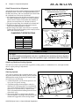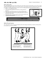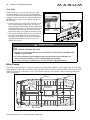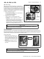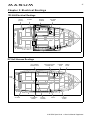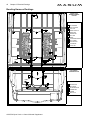
1
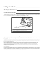
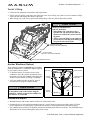
Port Engine Serial Number:
Stbd. Engine Serial Number:
Hull Identification Number:
The Hull Identification Number (HIN) is located on the starboard side of the swimstep. Be sure to record the HIN in
the space provided above and refer to the HIN for any correspondence or orders.
HIN
LOCATION
Record the HIN and the engine serial numbers in the space provided above.
Please refer to the HIN for any correspondence or orders.
© 2000 Maxum Marine Technical Publications. All rights reserved.
No part of this publication may be reproduced, stored in any retrieval system, or transmitted in any form by any means, electronic, mechanical,
photocopying, recording or otherwise, without prior written permission of Maxum. Printed in the U.S.A.
General Notes
The material in this document is for information only and is subject to change without notice. While reasonable efforts have been made in the
preparation of this document to assure its accuracy, Maxum assumes no liability resulting from errors or omissions in this document, or from
the use of information contained herein.
Due to our commitment to product improvement, Maxum reserves the right to make changes in the product design, specifications and
equipment at any time without notice or obligation. Illustrations and/or photos may show optional equipment. All Maxum products meet
or exceed USCG (Unites States Coast Guard) and/or NMMA (National Marine Manufacturer’s Association) construction standards.
Manufactured with 1,1,1 Trichloroethane, a substance which harms public health and environment during the manufacturing process by
destroying ozone in the upper atmosphere.
Proprietary Rights
This document discloses subject matter in which Maxum has proprietary rights. The information and design disclosed herein were originated
by and are the property of Maxum. Neither receipt nor possession thereof confers or transfers any right to reproduce, copy, alter or disclose the
document or any part thereof, any information contained therein, or to construct boats or any item from it, except by written permission from or
written agreement with Maxum. This document is to be returned upon request to Maxum.
Congratulations and welcome aboard
your new Maxum Sport Yacht!
Thank you for choosing our product. Maxum is committed to the goal of
building the highest quality products in the marine industry and to providing the finest after-the-sale support in the world.
Maxum has instituted an ongoing Total Customer Satisfaction Program.
The guiding principles of this program are:
• Design, build and support the finest marine products in the world, in
every market we serve.
• Be personally and individually responsible for the
customer’s total satisfaction.
• Remember that every customer has a choice, and we want them to
choose Maxum!
Welcome to the Maxum family. We are looking forward to serving
your boating needs, now and in the future!
CONTENTS
Chapter 1: Welcome Aboard!
1
1
1
2
2
2
2
3
Dealer Service
Boating Experience
Engines/Accessories Guidelines
Safety Standards
Structural Limitations
Qualified Maintenance
Special Care For Moored Boats
Hazard Warning Symbols
Chapter 2: Components/Systems
4
4
4
5
6
7
7
7
8
9
Dimensions & Tank Capacities
Layout View
Transom Hardware
Hullside Exterior Hardware & Drains
Helm Station
Yacht Lifting
Anchor Windlass (Option)
Windshield Wipers
Electrical System
12 Volt DC System
9
9
9
10
10
11
Fuses and Circuit Breakers
Batteries
Battery Switches
Parallel Battery Switch
Battery Charging
AC Electrical System
17
18
Audio & Visual Equipment
19
Navigation & Communication Equipment
16
16
17
17
Autopilot (Option)
Compass
Depth Finder (Option)
VHF Radio (Option)
Propulsion
19
19
20
21
22
22
22
Engines
Engine Room Ventilation System
Exhaust System
Engine Cooling System
Shaft-Transmission Alignment
Shaft Log Packless Sealing System
Controls
22 Steering System
23 Shifter/Throttle System
24 Trim Tabs
24
Bilge Pumps
25 Autofloat Switches
26
Fuel System
26
26
26
27
27
27
29
Fuel Transfer Pump
Fuel Quality
Fuel Filters & Separators
Fuel Fills
Anti-siphon Valves (Gas Engines Only)
Fuel System Routings
Freshwater System
29 Transom Shower
29 Water Heater
31
Sink and Shower Systems
31 Sump Box Cleaning
31 Sump System Winterization
32
Seawater Systems
32 Seacocks
32 Seawater Strainers
32 Raw Water Washdown (Option)
33
Marine Head & Holding Tank System
34 Manual Flush Head Systems
34 Vacuflush Head Systems (Option)
16 Dockside Cable Television & Telephone
Inlet (Option)
16
Appliances
18 Alcohol / Electric Stove
18 Vacuum System (Option)
18 Washer/Dryer (Option)
12 Shore Power
13 Inverter Power (Option)
14 Generator Power (Option)
16
Lighting
17 Spotlight (Option)
17 Navigation Lights
35
36
Air Conditioning & Heating (Option)
Warning Label Locations
Chapter 3: Electrical Routings
37
37
38
39
40
41
42
120 Volt Electrical Routings
DC Hull Harness Routings
Deck Harness Routings
Positive Battery Cable Routings
Negative Battery Cable Routings
Inverter Battery Cable Routings
Bonding Harness Routings
Chapter 4: Electrical Diagrams
43
44
45
46
AC Electrical System
DC Electrical System
Gas Engine Electrical System
Diesel Engine Electrical System
Appendix A: Express Limited Warranty
1
Chapter 1: Welcome Aboard!
This Owner’s Manual Supplement was prepared to provide specific information about your yacht. Please study the
Owner’s Manual and this Owner’s Manual Supplement carefully, paying particular attention to Appendix A:
Express Limited Warranty. Keep this Supplement on your yacht in a secure, yet readily available place.
Dealer Service
Make certain that you receive a full explanation of all systems from the selling dealer before taking delivery of your
yacht. Your selling dealer is your key to service. If you experience any problems with your new yacht, immediately
contact the selling dealer. If for any reason your selling dealer is unable to help, you can call us direct on our customer service hotline: 360-403-0274 or send us a FAX: 360-403-4235
Boating Experience
If this is your first boat or if you are changing to a type of boat you are not familiar with, for your own comfort and
safety, you must obtain handling and operating experience before assuming command of the boat.
Take one of the boating safety classes offered by the U.S. Power Squadrons or the U.S. Coast Guard Auxiliary. For
more course information, including dates and locations of upcoming classes, contact the organizations directly:
• U.S. Power Squadrons: 1-888-FOR-USPS (1-888-367-8777) or on the Internet at: http://www.usps.org
• U.S. Coast Guard Auxiliary: 1-800-368-5647 or on the Internet at: http://www.cgaux.org
Outside the United States, your selling dealer, national sailing federation or local yacht club can advise you of local
sea schools or competent instructors.
WARNING!
!
CONTROL HAZARD! A qualified operator must be in control of the yacht at all times. Do not
operate your yacht while under the influence of alcohol or drugs.
Engines/Accessories Guidelines
Your yacht’s engines and accessories were selected to provide optimum performance and service. Installing different
engines or other accessories will cause unwanted handling characteristics. Should you choose to install different
engines or to add accessories that will affect the yacht’s running trim, have an experienced marine technician perform
a safety inspection and handling test before operating your yacht again.
The engines and accessories installed on your yacht come with their own operation and maintenance manuals. You
must read and understand these manuals before operating the engines and accessories.
NOTICE
When storing your yacht please refer to your engine’s operation and maintenance manuals.
4100 SCA Sport Yacht
• Owner’s Manual Supplement
2
Chapter 1: Welcome Aboard!
Safety Standards
Your yacht’s mechanical and electrical systems were designed to meet safety standards in effect at the time it was
built. Some of these standards were mandated by law, all of them were designed to insure your safety, and the safety
of other people, vessels and property.
In addition to reading this owner’s manual supplement, read the owner’s manual and all accessory instruction
sheets for important safety standards and hazard information.
!
DANGER!
DANGER
PERSONAL SAFETY HAZARD! Do not allow anyone to ride on parts of the yacht
not designated for such use. Sitting on seat backs, lounging on the forward deck,
bow riding, gunwale riding, occupying the transom platform or occupying the
(optional) hardtop while underway is especially hazardous and will cause personal injury or death.
Structural Limitations
The command bridge, transom platform and bow platform are designed to be lightweight for proper boat balance.
The load limit for these platforms is 30 pounds per square foot, evenly distributed.
Qualified Maintenance
!
WARNING!
To maintain the integrity and safety of your yacht, only qualified personnel should perform
maintenance on, or in any way modify: The steering system, propulsion system, engine control
system, fuel system, environmental control system, electrical system or navigational system.
Failure to maintain your yacht’s systems (listed in the warning above) as designed could violate the laws in your
jurisdiction and will expose you and other people to the danger of bodily injury or accidental death. We recommend
that you follow the instructions provided in the Owner’s Manual, this Owner’s Manual Supplement, the engine
owner’s manual and all accessory instruction sheets/manuals included in your yacht’s owner’s packet.
Special Care For Moored Boats
If moored in saltwater or fresh water, your boat will collect marine growth on its hull bottom. This will detract from
the boat’s beauty, greatly affect its performance and may damage the gelcoat. There are two methods of slowing
marine growth:
• Periodically haul the boat out of the water and scrub the hull bottom with a bristle brush and a solution of soap and
water.
• The hull below the waterline was painted with anti-fouling paint by the factory. Occasionally you will need to repaint it with a good grade of anti-fouling paint.
NOTICE
• To help seal the hull bottom and reduce the possibility of gelcoat blistering on moored boats,
we recommend the application of an epoxy barrier coating, such as INTERLUX, Interprotect
2000E/2001E. The barrier coating should be covered with several coats of anti-fouling paint.
• Many states regulate the chemical content of bottom paints in order to meet environmental
standards. Check with your local dealer about recommended bottom paints, and about the
laws in effect in your area.
4100 SCA Sport Yacht
• Owner’s Manual Supplement
Chapter 1: Welcome Aboard!
3
Hazard Warning Symbols
The hazard boxes and symbols shown below are used throughout this supplement to call attention to potentially dangerous situations which could lead to either personal injury or product damage. Read these warnings carefully and
follow all safety instructions.
!
DANGER!
This symbol alerts you to immediate hazards which WILL cause severe personal injury or
death if the warning is ignored.
!
WARNING!
This symbol alerts you to hazards or unsafe practices which COULD result in severe personal
injury or death if the warning is ignored.
!
CAUTION!
This symbol alerts you to hazards or unsafe practices which COULD result in minor personal
injury or cause product or property damage if the warning is ignored.
NOTICE
This symbol calls attention to installation, operation or maintenance information, which is
important to proper operation but is not hazard related.
EXPLOSION
HAZARD!
OPEN FLAME
HAZARD!
HOT
HAZARD!
ELECTRICAL
HAZARD!
PERSONAL INJURY
& FALLING HAZARD!
4100 SCA Sport Yacht
ROTATING
PROPELLER HAZARD!
• Owner’s Manual Supplement
4
Chapter 2: Components/Systems
Dimensions & Tank Capacities
* Includes optional electronics package
Overall
Length
Max. Bridge
Clearance*
Beam
Draft
Fuel Capacity
(gal.)
Freshwater
Capacity (gal.)
Waste Tank
Capacity (gal.)
41’ 8"
18’ 2"
13’ 10"
3’ 9"
300
90
76
Layout View
DINETTE
TABLE
STEPS
SHOWER
AFT DOUBLE
BERTH
AFT BERTH
ESCAPE
HATCH
HEAD
ENTRY
STEPS
VANITY
FWD DOUBLE
BERTH
GALLEY
SHOWER
REFER
SALON
SEATING
HEAD
MICRO
VANITY
HANGING
LOCKER
STOVE
OVEN
Transom Hardware
SACRIFICIAL ANODE
DISK (TYPICAL)
TRANSOM
BOARDING
LADDER
PROPELLER
(TYPICAL)
4100 SCA Sport Yacht
SACRIFICIAL ANODE
(TYPICAL)
• Owner’s Manual Supplement
RUDDER
(TYPICAL)
TRIM TAB
(TYPICAL)
Chapter 2: Components/Systems
5
Hullside Exterior Hardware & Drains
STARBOARD HULLSIDE
AFT BILGE
PUMP
AFT HEAD
DRAIN
DOCKING LIGHT
(OPTION)
STARBOARD FUEL
TANK VENT
ANCHOR
CHAFE
PLATE
ENGINE
EXHAUST
ENGINE ROOM
BILGE PUMP
DECK DRAIN
GALLEY
SINK DRAIN
AIR CONDITION
DRAIN (OPTION)
DECK
DRAIN
GAS ENGINE (OPTION)
ENGINE EXHAUST
(TYPICAL PORT AND STARBOARD)
BILGE
PUMP
DOCKING LIGHT
(OPTION)
FORWARD
BILGE PUMP
PORT HULLSIDE
WASHER/DRYER
AFT BILGE
(OPTION)
PUMP DRAIN
AIR INTAKE
WASTE TANK
LOUVER (TYPICAL)
VENT
WATER TANK
VENT
MACERATOR
ANTI -SIPHON
VENT
ANCHOR
CHAFE
PLATE
CLAM SHELL
OVER ANCHOR
LOCKER DRAIN
FWD. SUMP
PUMP
PORT FUEL
TANK VENT
AFT SUMP
PUMP
DECK DRAIN
GENERATOR
EXHAUST (OPTION)
AIR CONDITIONER
PORT ENGINE
(OPTION)
EXHAUST BYPASS
4100 SCA Sport Yacht
• Owner’s Manual Supplement
6
Chapter 2: Components/Systems
Helm Station
CUP
HOLDERS
COMPASS
VHF RADIO
(OPTION)
INSTRUMENT
PANEL
RADAR
(OPTION)
STEREO
PORT
SWITCH
PANEL
DATA REPEATER
(OPTION)
CUP HOLDER
12 VOLT
RECEPTACLE
AUTO PILOT
(OPTION)
TILT
STEERING
SHIFTER/THROTTLE
(TYPICAL)
IGNITION
PANEL
CIRCUIT
BREAKER
PANEL
STBD.
SWITCH
PANEL
CHART PLOTTER
(OPTION)
INSTRUMENT PANEL
PORT ENGINE
HOUR METER
PORT ENGINE
PORT
TEMP. GAUGE VOLTMETER
PORT
VOLTMETER
PORT ENGINE
OIL GAUGE
PORT
TACHOMETER
STBD.
STBD.
STBD. ENGINE
TACHOMETER VOLTMETER TEMP. GAUGE
SYNCHRO.
GAUGE
STBD. ENGINE
OIL GAUGE
STBD. ENGINE
HOUR METER
STBD.
VOLTMETER
PORT SWITCH PANEL
STBD. SWITCH PANEL
FUEL
TRANSFER
TO STBD
DOCKING INSTRUMENT COURTESY NAV. ANCHOR
LIGHTS
LIGHTS
LIGHTS
LIGHT LIGHT
TRIM
TABS
4100 SCA Sport Yacht
FUEL
TRANSFER
TO PORT
HORN BLOWER AFT MID & FWD.
ACCY.
BILGE PUMPS SWITCHES
• Owner’s Manual Supplement
FUEL TRANS. BATT.
SWITCH PARALLEL
ANCHOR
WINDLASS
Chapter 2: Components/Systems
7
Ya ch t L i f ti n g
• Follow the lift equipment’s instructions and requirements.
• If bilge water is present, pump water out of the bilge areas before lifting your yacht. Excessive amounts of bilge
water can shift and change the balance of the load.
• When lifting your yacht, always position the lifting slings at the fore and aft sling label positions.
!
CAUTION!
FO
RE
FO
OT
PRODUCT OR PROPERTY
DAMAGE HAZARD!
• When lifting your yacht always use a
spreader bar. The spreader bar must be
equal to the width of the yacht at the lifting point.
• Always secure the slings to one another to
prevent the forward sling from sliding up
along the forefoot of the yacht.
FORWARD SLING LABEL
(TYPICAL PORT AND STARBOARD)
25’ 9 1/2"
AFT SLING LABEL
(TYPICAL PORT AND STARBOARD)
10’ 2 1/2"
END OF CHINE (REFERENCE POINT)
Anchor Windlass (Option)
Your yacht may feature an optional anchor windlass.
Read the manufacturer’s instruction manual supplied
in your yacht’s owner’s packet.
• To haul the anchor, use engine power (not the
windlass) to move the yacht to, and directly above,
the anchor. Activate the windlass to disengage the
anchor from the bottom by pulling it straight up.
• Verify the windlass breaker on the DC panel is
activated before using the windlass anchor.
!
VIEW OF FOREDECK
WINDLASS
ROPE LOCKER
WINDLASS FOOT
CONTROLS
ANCHOR
LOCKER
BOW CLEAT
CAUTION!
PRODUCT DAMAGE HAZARD!
Do not pull the yacht to the anchor using the
windlass or continue to operate the windlass if it
has stalled or is overloaded.
ANCHOR
ROLLER
FWD.
Windshield Wipers
• Windshield wiper and washer control switches are located at the helm.
• Periodically, due to wear and environmental exposure, you will need to replace wiper blades using 28" blade
refills. Instructions for replacing the wiper blades can usually be found on the blade replacement package.
• The windshield wiper fluid level should be checked occasionally and refilled as necessary. The windshield wiper
fluid bottle can be accessed through the galley floor cut-out.
4100 SCA Sport Yacht
• Owner’s Manual Supplement
8
Chapter 2: Components/Systems
Electrical System
Read this section and the electrical sections of the owner’s manual and all accessory manuals included in your
yacht owner’s packet. Electrical routing drawings are provided in Chapter 3 of this supplement, wiring schematics
in Chapter 4.
!
DANGER!
EXTREME FIRE, SHOCK & EXPLOSION HAZARD!
• To minimize the risks of fire and explosion, never install knife switches or other arcing
devices in the fuel compartments.
• Never substitute automotive parts for marine parts. Electrical, ignition and fuel system
parts were designed and manufactured to comply with rules and regulations that minimize
risks of fire and explosion.
• Do not modify the electrical systems or relevant drawings.
• Only qualified personnel should install batteries and/or perform electrical system
maintenance.
• Insure that all battery switches are in the off position before performing any work in the
engine spaces.
!
WARNING!
FIRE, OPEN FLAME & EXPLOSION HAZARD!
• Fuel fumes are heavier than air and will collect in the areas where they can be accidently
ignited. Visually and by smell (sniff test), check the engine and fuel compartments for fumes
or accumulation of fuel. Always operate the bilge blowers for at least four minutes prior to
engine starting, electrical system maintenance or activation of electrical devices.
• Minimize the danger of fire and explosion by not exposing batteries to open flame or sparks.
Do not smoke in the engine room or utility room.
!
CAUTION!
SHOCK & ELECTRICAL SYSTEM DAMAGE HAZARD!
Never disconnect the battery cables while the engine is running since it can cause
damage to your yacht’s electrical system components.
NOTICE
Electrical connections are prone to corrosion. To reduce corrosion caused electrical problems,
keep all electrical connections clean and apply a spray-on protectant that is designed to protect
connections from corrosion.
4100 SCA Sport Yacht
• Owner’s Manual Supplement
Chapter 2: Components/Systems
9
12 Volt DC System
Fuses and Circuit Breakers
The engines are protected by a large
circuit breakers located on the engines.
The accessories are protected by circuit
breakers on the battery switch panel in
the transom storage tub, by the accessory circuit breakers on the electrical
panel and by the circuit breakers under
the helm. Wires are color-coded to indicate which accessory each circuit
breaker services. Some items, such as
radios and bilge pumps, may be fused
individually at the unit. Auto-float
switches are fused at the battery.
Batteries
The batteries installed on your yacht
are located in the engine room (see
illustration to the right).
• The batteries supply electricity for
engine and (optional) generator
starting, as well as for your lights,
accessories and (optional) inverter.
• The power levels for the batteries
can be read on the voltmeters at the
helm instrument panel (see illustration to the right).
The electrical section of Chapter 8, in
the Owner’s Manual, provides battery
care and maintenance instructions.
Battery Switches
There are two battery switches installed
on your yacht, located inside the starboard transom storage tub.
• The PORT BATTERY switch, when
activated, provides power for starting the port engine and the
(optional) generator.
• The STBD. BATTERY switch,
when activated, provides power for
starting the starboard engine and
provides power for the accessories.
• After starting your yacht’s engines
or (optional) generator, the appropriate battery switches must be kept
ON until the engines and/or generator is turned OFF.
• Battery switches should be switched
to the OFF position whenever the
yacht is left unoccupied for long
periods of time.
BATTERY LOCATIONS
INVERTER
BATTERY
(OPTION)
PORT
ENGINE
STBD. ENGINE
& ACCESSORY
BATTERIES
FWD.
PORT ENGINE
AND (OPTIONAL)
GENERATOR
BATTERY
STBD.
ENGINE
PORT ENGINE &
(OPTIONAL) GENERATOR
BATTERY VOLTMETER
STBD. & ACCESSORY
BATTERIES VOLTMETER
VIEW OF TRANSOM STORAGE TUB
PORT BATTERY
SWITCH ACTIVATES
PORT ENGINE AND
(OPTIONAL) GENERATOR
BATTERY
BATTERY
SWITCHES
4100 SCA Sport Yacht
STBD. BATTERY
SWITCH ACTIVATES
BOTH STBD. ENGINE
AND THE ACCESSORY
BATTERIES
• Owner’s Manual Supplement
10
Chapter 2: Components/Systems
Parallel Battery Switch
The parallel battery switch is located at the helm on the starboard switch panel. Activating the parallel switch allows
you to combine the batteries power for emergency engine starting (when batteries are low).
• To use the parallel mode, make sure both battery switches are turned on. Hold down the parallel switch while
cranking the engine. Once the engine has started, release the switch.
!
CAUTION!
SYSTEM DAMAGE HAZARD!
The crossover (parallel) switch should only be used for emergency engine starting.
Battery Charging
Alternators
The alternators installed on your engines maintain proper charge levels for the engine and accessory batteries while
the engines are running (see “Table 1” below).
Battery Charger
Your yacht is equipped with a battery charger. Read the battery charger manual provided in your yacht’s owner’s
packet before using the charger.
• The battery charger, located in the engine compartment, can be accessed through the aft berth by removing the
access panel below the television cabinet.
• The battery charger’s circuit breaker is located on the AC panel and must be turned on for charging to occur.
• The battery charger will charge the batteries whenever the yacht is plugged into 120 volt shore power or the
(optional) generator is operating.
!
CAUTION!
• The battery charging systems (alternator and battery charger) are designed to charge conventional lead-acid batteries. Before installing gel-cell (or other new technology) batteries,
read and follow the battery charger’s operating instructions.
• Loose battery cable connections will damage your battery charger and your yacht.
Table 1: Battery Charging
Battery Charger
Stbd. Eng. Alternator
Port Eng. Alternator
Starboard Engine
Battery
Charges battery while
connected to shore power
or running generator.
Charges battery while
starboard engine is running.
Does NOT
charge battery.
Port Engine and
(optional) Generator
Battery
Charges battery while
connected to shore power
or running generator.
Does NOT
charge battery.
Charges battery while
port engine is running.
Accessory
Battery
Charges battery while
connected to shore power
or running generator.
Charges battery while
starboard engine is runnings.
Does NOT
charge battery.
4100 SCA Sport Yacht
• Owner’s Manual Supplement
Chapter 2: Components/Systems
11
AC Electrical System
Your yacht uses 120v/60Hz or (optional) 240v/60Hz AC (alternating current) systems. Τhe AC system can be energized by shore power, (optional) inverter or (optional) generator power. This system is designed so that the ship’s
power sources and the shore power cannot supply power simultaneously.
The AC panel’s master circuit breakers provide power source selections to the accessory breakers that are directly
below the designated master breaker. After activating AC power, individual breakers must be activated to supply
power to the accessories you wish to use.
NOTICE
When using shore power or generator power, the simultaneous operation of several AC accessories can result in an overloaded circuit. It may be necessary to turn off one accessory while
operating another.
!
CAUTION!
WATER HEATER DAMAGE HAZARD!
DO NOT energize the AC water heater electrical circuit until the heater is completely filled
with water. Even momentary operation in a dry tank will damage the heating elements. Warranty replacements will not be made on elements or tank damaged in this manner. The tank is
full if water flows from the tap when the hot water is turned on in the galley.
VOLTAGE INDICATOR
GAUGE
MASTER
BREAKER
(TYPICAL)
POLARITY
INDICATOR
LIGHT
(TYPICAL)
MASTER BREAKER
VOLTAGE SELECTOR
SWITCH
ACCESSORY
BREAKER
(TYPICAL)
4100 SCA Sport Yacht
• Owner’s Manual Supplement
12
Chapter 2: Components/Systems
Shore Power
30 Amp Shore Power
Your yacht features two standard-equipped 120v/30 amp shore power
receptacles (located inside the starboard transom stowage tub). The
receptacles inlet, labeled line 1 and line 2, correspond to the master
breakers, labeled line 1 and line 2 on the AC panel. This system is
designed so that each line operates independent of each other.
30 AMP SHORE POWER INLETS
AND BREAKER
30 AMP SHORE
POWER INLETS
MAIN
BREAKERS
NOTICE
• Some dockside installations may be rated less than 30
amps, therefore, you may need to purchase lower amp
adapters.
• Adapters should always be used at the dockside end of a
shore power cord.
• Whenever a lower amp adapter is used, however, there will
be a corresponding drop in supplied power from the dockside system.
50 Amp Shore Power (Option)
A single 50 amp receptacle inlet may be installed in place of the two
standard 30 amp receptacle inlets. Electricity from the single 50 amp
inlet (240 volt) is evenly distributed to both line 1 and line 2 master
breakers (120 volt) on the AC panel. This system is designed so that
each line operates independent of each other.
(OPTIONAL) 50 AMP SHORE POWER INLET
AND BREAKER
50 AMP SHORE
POWER INLET
MAIN
BREAKER
TV/TELEPHONE
INLET (OPTION)
Connecting To Shore Power
1.
2.
3.
Monitor the AC panel’s polarity indicator lights (next to the line 1 and line 2 master breakers) as follows:
• A green light illuminating after the power cord is plugged into the yacht’s external power receptacle indicates acceptable electrical power in which you may energize the main breaker switches.
• A red light, however, indicates reversed polarity, which could cause electrical system damage and possibly
electrical shock injuries. In this case, do not energize the main breaker switches (see warning below).
Activate the AC system by turning the main ship/shore breaker(s) to the dockside position.
Turn on the master breaker and individual component breakers (below the activated master breaker) as required.
NOTICE
Voltage on each line can be read by setting the voltmeter selector switch.
!
WARNING!
SHOCK & ELECTRICAL SYSTEM DAMAGE HAZARD!
• Monitor the polarity indicator lights every time you connect to shore power.
• When connecting to shore power and you encounter reversed polarity light (red colored),
Do not energize the main breaker switches. Instead, immediately disconnect the shore power
cord (always from the dockside receptacle first) and notify marina management.
4100 SCA Sport Yacht
• Owner’s Manual Supplement
Chapter 2: Components/Systems
!
13
DANGER!
FIRE, EXPLOSION & SHOCK HAZARD!
• DO NOT alter shore power connectors and use only compatible connectors.
• Before connecting or disconnecting the shore power cord to your yacht, verify all breakers
and switches on the AC master panel are turned OFF.
• To prevent shock or injury from an accidental dropping of the “hot” cord into the water,
ALWAYS attach the shore power cord to the yacht inlet first; then to the dockside connection. When disconnecting from shore power, disconnect the shore power cord from the
dockside connection first.
• NEVER leave a shore power cord connected to the dockside connection only.
• Only use shore power cords approved for marine use. NEVER use ordinary indoor or outdoor extension cords that are not rated for marine use.
!
CAUTION!
SHOCK & ELECTRICAL SYSTEM DAMAGE HAZARD!
• NEVER connect dockside power to your yacht outside North America unless you have purchased the international electrical conversion option.
• The simultaneous use of several AC components can result in an overloaded circuit. It may
be necessary to turn off one or more accessories in order to use another accessory.
• Use double insulated or three-wire protected electrical appliances whenever possible.
• Periodically check the shore power cord(s) for deterioration or damage. Damaged or faulty
cords should NEVER be used since the danger of fire and electrical shock exists.
• DO NOT pinch shore power cords in doors or hatches, or coil the shore power cord too
tightly since these situations can generate enough heat to result in a fire.
• If a shore power cord should accidently become immersed in water, it should immediately
be sprayed with fresh water. THOROUGHLY dry the blades and contact slots and spray
with a moisture displacement before reusing.
Inverter Power (Option)
Your yacht may feature an (optional) inverter which converts DC power from it’s battery to AC power for designated
accessories. The inverter is located in the utility room and can be accessed by removing the forward entry steps.
Before operating the inverter, read the inverter manual for detailed operating procedures and safeguards and observe
the following:
• Accessories that can be powered by the inverter are identified by white breakers on the AC panel.
• Activate the AC system under inverter power by switching on the inverter master breaker (located above the port
dinette) and pressing the on/off switch on the inverter control panel (located on the inverter).
• The inverter runs off it’s own battery, which is located forward of the starboard engine, (see illustration on the top
of page 9). The inverter battery breaker is located on the battery switch panel inside the port transom storage tub.
• The inverter features a built-in battery charger. The battery charger will charge it’s battery whenever the yacht is
plugged into a dockside connection or the (optional) generator is on.
4100 SCA Sport Yacht
• Owner’s Manual Supplement
14
Chapter 2: Components/Systems
Generator Power (Option)
Your yacht may come equipped with an
(optional) gas or diesel generator. Prior to
initially operating your generator, read the
generator manual for detailed information on
pre-start checks, break-in procedures and
starting instructions.
Observe the following about your generator:
• Polarity has been established in the installation of the generator, therefore the polarity lights will not function while operating
the generator.
• The generator and the port engine use the
same battery (see illustration on page 9).
• Generator oil pressure, water temperature,
and voltage gauges are located on the
main distribution panel in the aft salon.
• The generator’s main circuit breaker is
located on the generator.
• The starboard fuel tank supplies the
generator’s fuel.
• In addition to servicing the filters attached
to the generator, the filters/separators
(located near the fuel line valves) should
be serviced as described in the manufacturer’s manual.
• The coolant mixture installed at the factory consists of equal parts of water and
antifreeze (Ethylene Glycol). The coolant
bottle for the main generator is located aft
of the salon engine access hatch opening
(refer to photograph on page 21).
• Frequently check the generator’s seawater
strainer for leaks and/or debris (refer to
Sea Strainer section on page 32).
!
GENERATOR GAUGES
TEMPERATURE
GAUGE
GENERATOR CONTROLS
OIL PRESSURE
GAUGE
VOLTAGE
INDICATOR
GAUGE
MAIN DISTRIBUTION PANEL
CAUTION!
SYSTEM DAMAGE HAZARD!
• Always verify the generator’s seawater pickup system’s intake seacock is in the open
position prior to starting and throughout generator operation.
• Never operate the generator starter for more than 30 seconds. If the generator does not
start, wait at least 30 seconds before another start attempt is made.
• After starting the generator, wait for the generator to stabilize before activating component
breakers on the AC panel.
4100 SCA Sport Yacht
• Owner’s Manual Supplement
Chapter 2: Components/Systems
15
Generator starting:
1.
Open the generator’s seawater intake valve (seacock) before starting the generator and keep the seacock valve
open during generator operation.
2. Operate the bilge blowers for a minimum of four minutes before starting the generator. Leave the blowers on
while the generator is operating if your yacht is running at below cruising speed.
3. Verify that the generator’s battery switch, located in the starboard transom tub (refer to photograph on page 9),
is turned on.
4. Diesel Generator: On the AC panel, press and hold the pre-heat switch on for one minute for pre-heating.
While holding the generator’s pre-heat switch, activate the start switch. As the generator starts, continue to hold
the pre-heat switch until oil pressure is indicated on the pressure gauge.
Gas Generator: Simultaneously press the oil pressure button and activate the start switch.
5. On the AC panel, slide the master breaker’s T-bar from the dockside power to generator power.
6. Switch the sub-main breaker on.
7. Activate each individual component breaker as required.
8. The master breaker selector switch (line 1 or line 2) should be selected, for the voltage indicator gauge to display AC power from the generator.
To shut off the generator: Hold the “off” switch until the generator shuts down.
GENERATOR SYSTEM
GENERATOR
BATTERY
SWITCH
TO THRU-HULL
ANTI-SIPHON
VENTED LOOP
GENERATOR
MUFFLER
TO VENT IN
HULLSIDE
SEAWATER
STRAINER
WATER HOSE
SEAWATER INTAKE
VALVE (SEACOCK)
GENERATOR
GENERATOR
FUEL FILTER
GENERATOR
RETURN LINE
(DIESEL ONLY)
FUEL LINE TO
GENERATOR
FUEL SHUT OFF
VALVE
STARBOARD
FUEL TANK
4100 SCA Sport Yacht
• Owner’s Manual Supplement
16
Chapter 2: Components/Systems
Audio & Visual Equipment
All audio and visual equipment installed on your yacht have separate instruction sheets or manuals that explain their
operating procedures in detail.
NOTICE
AM radio reception may be impaired anytime the engines are running.
Dockside Cable Television & Telephone Inlet (Option)
Your yacht may be equipped with an (optional) dockside cable television and telephone inlet, located inside the transom storage tub (refer to photograph on page 12). Your yacht must be hooked up to a dockside source to use a telephone or receive cable television transmission.
Navigation & Communication Equipment
The owner’s packet contains operation manuals for all navigation & communication equipment installed on your
yacht. Read these manuals before operating the equipment and follow the safety warnings below.
Autopilot (Option)
Your yacht may feature an (optional) autopilot system which can be activated from the helm. The autopilot will automatically aid you in maintaining the chosen direction of your yacht. Read the manufacturer’s instructions supplied in
your owner’s packet and observe the following:
!
WARNING!
PERSONAL INJURY & PRODUCT HAZARD! Never leave the helm while the autopilot system is on! Someone should always stay at the helm as a lookout in case a dangerous situation
suddenly develops.
NOTICE
Τhe autopilot system is only an aid to navigation. Its accuracy can be affected by many factors,
including equipment failure or defects, environmental conditions & improper handling or use.
Compass
NOTICE
Compass accuracy can be affected by many factors. You must have a qualified technician calibrate your compass. Make sure the technician gives you a deviation card which shows the corrections to apply in navigational calculations. Keep a copy of the deviation card at the helm.
4100 SCA Sport Yacht
• Owner’s Manual Supplement
Chapter 2: Components/Systems
17
Depth Finder (Option)
!
WARNING!
• Do not use the depth finder as a navigational aid to prevent collision, grounding, yacht damage or personal injury.
• When the yacht is moving, submerged objects will not be seen until they are already
under the yacht. Bottom depths may change too quickly to allow time for the yacht
operator to react. If you suspect shallow water or submerged objects, operate your yacht at
very slow speeds.
VHF Radio (Option)
Your yacht may include an (optional) VHF (Very High Frequency) radio at the helm. The VHF radio can be used to
access weather reports, summon assistance or contact other vessels as permitted by the FCC (Federal Communications Commission). Contact the FCC for licensing, rules and regulations concerning VHF radio usage.
Lighting
The lights on your yacht are of top quality, but you should be aware that failure may occur for a variety of reasons:
1.
2.
3.
4.
There may be a tripped breaker - reset the breaker switch.
The bulb may be burned out - carry spare bulbs for replacement.
The bulb base may be corroded - clean the base and coat it with non-conductive electrical lubricant.
A wire may be damaged or may have come loose - repair as required.
!
CAUTION!
Prolonged operation of interior lights (overnight) will result in a drained battery. Be conservative in the use of battery power.
Spotlight (Option)
Your yacht may come equipped with an (optional) spotlight located on the command bridge. The spotlight is controlled from a switch at the helm. Operating instructions can be found in the spotlight’s operating manual, which is
included in your yacht’s owner’s packet.
Navigation Lights
Navigation lights are essential to safe navigation at night. Read the Coast Guard publication included in your
owner’s packet and if necessary take a boating safety class.
!
CAUTION!
Avoid storage of gear where it will block navigational lights from view.
4100 SCA Sport Yacht
• Owner’s Manual Supplement
18
Chapter 2: Components/Systems
Appliances
All appliances installed on your yacht come with their own manuals (supplied in your yacht’s owner’s packet)
that explain detailed operating instructions and important safeguards. Read these manuals before operating your
yacht’s appliances.
• Appliances operate on 120 volt AC power, which may be supplied from shore power, generator (option) power or
inverter (option) power.
• Make sure the AC breaker is activated for the appliance you wish to turn on.
Alcohol / Electric Stove
!
WARNING!
EXPLOSION, SCALDING & FIRE HAZARD!
• DO NOT operate the stove unless you have read the owner’s manual from the manufacturer. Use these instructions only as a reminder.
• Any non-cooking devices on or near your stove during operation are potential fire hazards!
• Do not operate the stove while underway.
• Open flame cooking appliances consume oxygen, this can cause asphyxiation or death.
Maintain open ventilation.
NOTICE
Always keep an approved ABC-type fire extinguisher in galley area.
Vacuum System (Option)
Your yacht may feature a vacuum system. The vacuum system receptacle is located inboard and below the forward
dinette lounge seat. The breaker on the AC panel must be activated to operate the vacuum system. Read the instructions in your owner’s packet before operating.
Washer/Dryer (Option)
Your yacht may feature a washer/dryer located in the aft port area of the aft berth. The breaker on the AC panel must
be activated to operate the washer/dryer. Read the instructions in your owner’s packet before operating.
4100 SCA Sport Yacht
• Owner’s Manual Supplement
Chapter 2: Components/Systems
19
Propulsion
Engines
The owner’s packet contains detailed engine operation and maintenance manuals. Read and understand these manuals before operating or performing maintenance to the engines.
Engine Room Ventilation System
The bilge blowers remove fumes from the engine compartment and draws fresh air into the compartment through
the deck vents. To ensure fresh air circulation, operate the bilge blowers for at least four minutes prior to starting
the engines (or optional generator), during starting, and while operating your yacht below cruising speed.
WARNING!
!
EXPLOSION HAZARD!
• Operation of the blower system is not a guarantee that explosive fumes have been removed.
If you smell any fuel, do not start the engines. If the engines are already running, immediately shut off the engines and all electrical accessories and investigate immediately.
• Do not obstruct or modify the ventilation system.
Bilge Blower Routing
BILGE BLOWER ROUTING
BLOWER HOSES
FROM BLOWERS
STBD. FUEL
TANK
AIR INTAKES
4100 SCA Sport Yacht
• Owner’s Manual Supplement
20
Chapter 2: Components/Systems
Exhaust System
The exhaust system is designed to keep water out of the engines in most sea conditions, however, do not anchor the
stern to sea or shut engines off if the seas are too high. Always use good seamanship and consider the sea conditions
before anchoring or shutting off the engines.
NOTICE
Check all exhaust system hose clamps after the first 20 hours and continue to check all of the
clamps periodically after that.
Gas Exhaust System Routings
VIEW OF STARBOARD EXHAUST ROUTING
(PORT SIDE IS SIMILAR AND OPPOSITE)
EXHAUST HOSE
& HOSE CLAMPS
MUFFLER
ELBOW
TO ENGINE
EXHAUST HOSE
& HOSE CLAMPS
EXHAUST
TUBE
STRAP
(TYPICAL)
TO
THRU-HULL
ELBOW
Diesel Exhaust System Routings
PORT ENGINE EXHAUST SYSTEM
STBD. ENGINE EXHAUST SYSTEM
A
D
D
E
E
G
C
B
B
B
K
J
B
F
B
C
C
K
A
B
C
F
CROSS SECTION VIEW OF
PORT EXHAUST THRU HULL
STBD. EXHAUST IS OPPOSITE
J
H
B
I
4100 SCA Sport Yacht
J
• Owner’s Manual Supplement
A. ENGINE
B. ELBOW
C. EXHAUST TUBE
D. WATER HOSE
E. RISER
F. BUSHING
G. HOSE HUMP
H. THRU HULL
I. HULLSIDE
J. EXHAUST HOSE
K. AFT BERTH BULKHEAD
J
Chapter 2: Components/Systems
Engine Cooling System
The engine cooling system circulates raw water
around components and also uses a (freshwater) heat exhanger on the engine to reduce
engine temperature.
• Make sure both of the engine’s seawater
intake seacocks are open before starting the
engines and keep the seacocks open while
the engines are running.
!
21
TYPICAL ENGINE COOLING SYSTEM ROUTING
SEAWATER
STRAINERS
CONNECTS TO
RAW WATER PUMP
INLET ON ENGINES
CAUTION!
SYSTEM DAMAGE HAZARD!
The engine cooling system’s seacocks must
be in the open position before engines are
started and while the engines are operating.
• The engine cooling system’s seawater
strainers should be checked for leaks and
debris every time you use your yacht. For
instructions on how to clean the seawater
strainers of debris, see the Seawater Strainer
section of this Supplement.
• Engine coolant (antifreeze) levels should be
checked at the engine-mounted expansion
tanks and at the coolant recovery bottles.
SEAWATER INTAKE VALVE (SEACOCK)
COMPONENTS (TYPICAL)
SEACOCK (TYPICAL)
SEACOCK GASKET
SEACOCK
LEVER
HULL
SECTION
INTAKE STRAINER
GENERATOR & ENGINE COOLANT BOTTLE LOCATIONS
BOTTOM
ENTRY STEP
GENERATOR
COOLANT
BOTTLE
SALON
FLOOR
!
CAUTION!
SCALDING HAZARD!
Never check coolant levels when the engine is hot
or while the engine is operating.
ENGINE COOLANT BOTTLES
4100 SCA Sport Yacht
• Owner’s Manual Supplement
22
Chapter 2: Components/Systems
Shaft-Transmission Alignment
TYPICAL TRANSMISSION-TO-PROP SHAFT COMPONENTS
Alignment between the engine transmission output shaft and
the propeller shaft is critical. This alignment had been performed at the factory, and was rechecked by the dealer after
the yacht had been in the water for 48 hours.
• An alignment inspection should be performed as part of
the routine maintenance program by a marine mechanic
after the initial 30 hours of operation, then annually or
whenever an unusual noise or vibration is noticed.
• The gap between flange faces should be less than 0.003".
• Replacement flange bolts, nuts and washers must be
corrosion resistant and grade 8 or better.
• Recheck flange bolt torque after 20 hours of operation.
Tighten the flange bolts according to the torque specifications listed in the table below.
TRANSMISSION-TO-PROP SHAFT COMPONENTS VARY,
DEPENDING UPON ENGINE TYPE AND SIZE
DETAILED VIEW
SECTION VIEW
OF HULL
CLAMPS
FLANGE BOLT SPECIFICATIONS
BOLT SIZE
TORQUE
3/8" - 24
7/16" - 20
1/2" - 20
5/8" - 18
M16 x 1.5
40 +/- 7 lb.
65 +/- 10 lb.
95 +/- 15 lb.
200 +/- 30 lb.
175 +/- 25 lb.
CARBON/GRAPHITE
FLANGE
ROTOR
BELLOWS
SHAFT LOG
(TRIANGLE FLANGE)
!
TRANSMISSION
OUTPUT FLANGE
COUPLER
SHAFT
FLANGE BOLT (TYPICAL)
POSSIBLE QUANTITY
4, 6 OR 8 BOLTS
CAUTION!
• A marine mechanic should perform the shaft/transmission alignment, since it requires moving
the engine.
• If a shaft/transmission misalignment exists, have a qualified marine mechanic perform an alignment
as soon as possible. Continued use may lead to premature engine, transmission, shaft, shaft seal and/
or hull damage!
Shaft Log Packless Sealing System
The shaft seal, which is part of the shaft log packless sealing system, is a maintenance-free, watertight seal that
doesn’t require packing or adjustments.
Controls
Steering System
STEERING SYSTEM ROUTING
Your yacht is equipped with a manual hydraulic steering system. Before using the steering system, read and
understand the steering section in your owner’s manual, and observe the following:
• A manual hydraulic system will not operate as easily as your car’s power steering.
• A rhythmic pulsing when turning the wheel is a
characteristic of the pump and is not a malfunction.
Also, when coming off a hard-over position, a resistance may be felt, followed by a distinct sound.
This is a normal situation resulting from the release
of the check valve.
• The steering fluid level and pressure should be
checked regularly, according to the instructions and
maintenance suggestions in the steering manual.
4100 SCA Sport Yacht
• Owner’s Manual Supplement
AFT
RUDDER
ARM ASSY
TIE BAR
STEERING
CYLINDER
Chapter 2: Components/Systems
23
Rudder Stuffing Gland
The rudder stuffing gland is part of the assembly where the rudders emerge from the bottom of your yacht. The shaft
stuffing gland should not leak any water. If a leak develops, it can usually be stopped by tightening the packing gland
nuts slightly. If stuffing gland leakage becomes excessive, packing replacement can be performed as follows:
1.
2.
3.
4.
5.
6.
Remove your yacht from the water.
Loosen the packing gland nuts and back the packing gland from
the sleeve.
Remove the old packing and wrap new packing around the shaft.
Cut the rings with a razor blade at an angle approximately 30 degrees to
the long axis of the shaft.
Stagger the ends of each ring around the shaft and insure that the ring
are at the bottom in the sleeve.
Tighten the packing gland nuts until resistance is felt.
RUDDER DETAIL
(TYPICAL PORT AND STBD.)
AFT
RUDDER
BEARING
RUDDER
RUDDER
STUFFING BOX
CAUTION!
!
PRODUCT DAMAGE HAZARD! DO NOT over tighten the packing gland nuts.
Shifter/Throttle System
The shifter throttle controls are located at the helm station. We strongly recommend you read the operating instructions outlined in your Owner’s Manual.
SHIFTER/THROTTLE
RESERVOIR
PORT
SHIFT
STBD.
THROTTLE
PORT
THROTTLE
STBD.
SHIFT
7
1
5
12
8
11
6
2
PORT
SERVO
PORT
SERVO
STBD.
SERVO
STBD.
SERVO
10
4
9
3
ROUTING KEY
1
2
3
4
5
6
PORT THROTTLE TO RESERVOIR
PORT THROTTLE TO PORT THROTTLE SERVO
PORT THROTTLE SERVO TO RESERVOIR
STBD. THROTTLE SERVO TO RESERVOIR
STBD. THROTTLE TO RESERVOIR
STBD. THROTTLE TO STBD. THROTTLE SERVO
7 PORT SHIFTER TO RESERVOIR
8 PORT SHIFTER TO PORT SHIFTER SERVO
9 PORT SHIFTER SERVO TO RESERVOIR
10 STBD. SHIFTER SERVO TO RESERVOIR
11 STBD. SHIFTER TO RESERVOIR
12 STBD. SHIFTER TO STBD. SHIFTER SERVO
4100 SCA Sport Yacht
• Owner’s Manual Supplement
24
Chapter 2: Components/Systems
Trim Tabs
The trim tabs may be used to help keep your yacht
level at cruising speeds. Trim tabs are controlled by
two rocker switches, located at the helm station. Before
using the trim tabs, read the trim tab operation manual
included in your yacht’s owner’s packet and observe
the following:
• Once the best bow cruising trim is reached, use the
port or starboard trim switches (one at a time) to
correct unequal lateral loading. Trim tab adjustment
should be performed by several short touches to the
switch rather than one long one. After each short
touch allow about five seconds for the hull to react.
• The trim tab hydraulic fluid reservoir is located in
the engine compartment on the aft transom (see
illustration to the right). The fluid level should be
checked periodically (at least once a year) and
refilled as necessary.
TRIM TAB PUMP LOCATION
TRIM TAB
PUMP
AFT
TRIM TAB
(TYPICAL)
STBD.
TRANSOM
WARNING!
!
LOSS OF CONTROL HAZARD!
• Improper use of trim tabs will cause loss of control! Do not allow anyone unfamiliar with
trim tabs to operate them.
• Do not use trim tabs in a sea running the same direction as the yacht (a following sea)
as they will cause broaching or other unsafe handling characteristics.
• Do not use trim tabs to compensate for excessive unequal weight distribution.
Bilge Pumps
Your yacht is equipped with five automatic impeller-type bilge pumps which are used to pump water out of the bilge.
Bilge pumps are controlled by automatic bilge pump float switches (autofloat switches) and/or switches at the helm
and are wired directly to the battery so they will normally function even when the yacht is completely shut down
and left unattended.
BILGE PUMP ROUTING
TO
THRU-HULL
BILGE PUMP &
FLOAT SWITCH
BILGE PUMP &
FLOAT SWITCH
BILGE PUMP &
FLOAT SWITCH
TO
THRU-HULL
4100 SCA Sport Yacht
TO
THRU-HULL
• Owner’s Manual Supplement
TO
THRU-HULL
Chapter 2: Components/Systems
Bilge Pump Testing
Bilge pumps should be checked often to verify that they are
working properly. To test a bilge pump’s operation, activate
the dash-mounted switch and verify that bilge water is pumped
overboard. If bilge water is present and the pump motor is running but not pumping, inspect the discharge hose for a kink or
collapsed area. If no problems are found, check the bilge pump
housing for clogging debris as follows:
1.
2.
Remove the power cartridge:
a. Lift the tab while rotating the fins counterclockwise.
b. Lift out the power cartridge.
c. Clear the outer housing of debris.
Reinstall the power cartridge:
a. Make sure the “O” ring is properly seated.
b. Coat the “O” ring with a light film of vegetable or
mineral oil.
c. Align the two cams on either side of the power
cartridge with the two slots on the outer housing and
press the power cartridge into the housing while
twisting clockwise. To ensure proper reinstallation,
attempt to twist the fins counterclockwise without lifting the tab; the cartridge should stay in place.
25
BILGE PUMP
COMPONENTS
TAB
“O” RING
FIN
OUTER
HOUSING
LIGHT
FILM
OF OIL
SLOT (TYPICAL)
CAM
(TYPICAL)
POWER
CARTRIDGE
NOTICE
Discharge of oil, oil waste or fuel into navigable waters is prohibited by law. Violators are
subject to legal action by the local authorities.
Autofloat Switches
Automatic bilge pumps use electromagnetic float (autofloat) switches to automatically activate the pump whenever
bilge water accumulates above a preset level. One autofloat switch is mounted next to the bilge pump it activates, and
is wired directly to the battery so it will function even when the yacht is completely shut down and left unattended.
Autofloat switches should be tested often for proper operation as follows:
To test a float switch:
FLOAT SWITCH OPERATION
1. Push the float switch test button up to
activate the bilge pump. If the pump does
not turn on, check the inline fuse. If the
fuse is good but the switch doesn’t work,
it may indicate a bad switch or possibly a
low battery.
2. Push the test button all the way down
to return the float switch back into the
auto mode.
FLOAT SWITCH
TEST BUTTON
(TYPICAL)
!
FLOAT UP - TEST MODE
FLOAT DOWN - AUTO MODE
BILGE PUMP SHOULD TURN ON
BILGE PUMP SHOULD TURN OFF
CAUTION!
When test is completed the float switch, you MUST push the test button all the way down to the
auto position to turn the switch back into auto mode!
4100 SCA Sport Yacht
• Owner’s Manual Supplement
26
Chapter 2: Components/Systems
Fuel System
Read the fuel section of the Owner’s Manual and the engine operation manual, paying special attention to the subject
of fuel recommendations.
!
WARNING!
FIRE, EXPLOSION AND OPEN FLAME HAZARD!
• It is very important that the fuel system be inspected thoroughly the first time it is filled and
at each subsequent filling.
• The fueling instructions in the Owner’s Manual and the fuel recommendations in the engine
operation manual must be followed.
!
CAUTION!
• Diesel: Air in the diesel supply system can stop an engine or severely restrict performance. If
you suspect air in the fuel lines, refer to your engine operation manual for detailed instructions on how to bleed the system.
• Avoid the storage or handling of gear near the fuel lines, fittings and tanks.
NOTICE
Discharge of fuel into navigable waters is prohibited by law. Violators are subject to legal
action by the local authorities.
Fuel Transfer Pump
The fuel transfer pump is used to draw fuel from a full tank to a nearly empty tank. The fuel transfer pump is activated by the fuel transfer switch, located at the helm station.
!
CAUTION!
ENVIRONMENTAL HAZARD! NEVER transfer fuel into a full (or nearly full) fuel tank. Fuel
transferred into a full tank may spill overboard through the tank venting system.
Fuel Quality
• Make sure your fuel suppliers are reputable and can be relied upon to furnish clean, high quality fuel. Once you
have found such suppliers, keep your tanks as full as possible with their fuel (allowing for expansion due to temperature variations). Then, if you are forced to add a potentially poor quality fuel supply to the tank, the portion of
poor quality fuel will be minimized.
• Consult your dealer or local marina about fuel additives that help prevent fungus or buildup inside the fuel tanks.
Fuel Filters & Separators
Fuel filters and separators should be replaced periodically according to the guidelines and instructions detailed in
your engine manual, optional generator manual and in any filter literature included in your boat’s owner’s packet.
4100 SCA Sport Yacht
• Owner’s Manual Supplement
Chapter 2: Components/Systems
27
Fuel Fills
Fuel fill receptacles are located on each side of the deck and are marked either “Diesel” or “GAS”. If you experience
difficulty filling a fuel tank, check to see that the fuel fill and vent lines are free of obstructions and kinks.
STBD. FUEL FILL SHOWN
(PORT SIDE TYPICAL)
FWD. STBD.
FUEL FILL
WINDSHIELD
FUEL TANK FILL AND VENT ROUTING
(TYPICAL PORT & STARBOARD)
TO DECK FUEL FILL FITTING
PORT FUEL TANK
FUEL VENT
FITTING IN
HULL
FWD.
Anti-siphon Valves (Gas Engines Only)
An anti-siphon valve is an integral part of the fuel line barb fitting on each fuel tank. These valves are spring loaded
and are opened by fuel pump vacuum. If a fuel line ruptures, the valve prevents the siphoning of fuel from the tank.
WARNING!
!
FIRE/EXPLOSION HAZARD! If an engine problem is caused by fuel starvation,
check the anti-siphon valve. If the valve is stuck or clogged, shut down the engine
and replace it. Except in an emergency, never operate the engines without the antisiphon valve.
Fuel System Routings
PORT FUEL TANK
GAS FUEL LINE
ROUTING DIAGRAM
STBD. FUEL TANK
PORT FUEL TANK
STBD. FUEL TANK
DIESEL FUEL LINE
ROUTING DIAGRAM
RETURN
(W/O SCREENS)
RETURN
(W/O SCREENS)
SENDER
SENDER
PICK-UP
(W/ANTI-SYPHON)
(W/SCREEN)
PICK-UP
(W/ANTI-SYPHON)
(W/SCREEN)
VENT
VENT
SENDER
PICKUP
(W/O SCREENS)
VENT
FUEL FILL
FUEL FILL
FUEL
TRANSFER
PUMP
SENDER
PICKUP
(W/O SCREENS)
SHUT
OFF
VALVE
SHUT
OFF
VALVE
FUEL FILL
FUEL FILL
VENT
FUEL
FILTER
FUEL
FILTER
SHUT
OFF
VALVE
PORT
ENGINE
GENERATOR
(OPTION)
STARBOARD
ENGINE
STARBOARD
ENGINE
PORT
ENGINE
FUEL
FILTER
GENERATOR
(OPTION)
4100 SCA Sport Yacht
• Owner’s Manual Supplement
28
Chapter 2: Components/Systems
DIESEL FUEL SYSTEM
NOTE: GENERATOR OPTION NOT SHOWN
FUEL FILTER
PORT FUEL TANK
FUEL RETURN
FUEL TRANSFER
FUEL PICK-UP
FUEL TRANSFER
PUMP
STBD. FUEL TANK
FUEL RETURN
FUEL TRANSFER
FUEL PICK-UP
FUEL SHUT OFF
VALVE
FUEL FILTER
FUEL SHUT OFF
VALVE
TO
ENGINE
TO ENGINE
PORT
STBD.
RETURN
RETURN
FWD.
FWD.
GAS FUEL SYSTEM
NOTE: GENERATOR OPTION NOT SHOWN
STBD. FUEL TANK
PORT FUEL TANK
FUEL SHUT OFF
VALVE
FUEL PICK-UP
FUEL PICK-UP
FUEL SHUT OFF
VALVE
TO ENGINE
STBD.
TO ENGINE
PORT
FWD.
FWD.
4100 SCA Sport Yacht
• Owner’s Manual Supplement
Chapter 2: Components/Systems
29
Freshwater System
MAIN DISTRIBUTION PANEL
Your yacht features a pressure-demand freshwater system.
• The water tank fill fitting is located on aft deck boarding step. The city water inlet is located on the starboard
side of the aft cockpit (see photograph to the right).
• When not connected to a dockside water supply, the
water pump’s DC breaker must be turned on to
use freshwater.
• The water pump’s DC breaker should be turned off
when any of the following occurs:
3 When the yacht is not in use.
3 Whenever the water tank is empty.
3 When connected to a dockside water supply.
• The water filter should be inspected and cleaned often.
• Drain the freshwater system in winter months and
when not in use to prevent damage and to keep stored
water from becoming stagnant and distasteful. Should
it become necessary to disinfect the freshwater system,
ask your dealer about treatments available for your
yacht’s system.
• The water tank, located under the aft berth mattress, is
equipped with a water level indicator (located on the
AC panel). The indicator may not be 100% accurate, so
it is recommended that the water tank be topped off at
every opportunity to avoid the possibility of running
short of freshwater.
• A pressure accumulator tank is installed in the freshwater system. The pressure accumulator tank assists
the pressure pump by reducing on/off cycling and distributing an even flow of water.
WATER HEATER
BREAKER
WATER TANK
GAUGE
WATER PUMP
SWITCH
AFT TRANSOM
TRANSOM
SHOWER
CITY WATER
INLET
FILL FITTING
WATER TANK
AFT DECK
BOARDING
STEP
Transom Shower
Your yacht is equipped with a freshwater transom shower. It is located above the transom storage area (see photograph above). The water pump switch MUST be activated before using the transom shower. Read the manufacturer’s
operating instructions, provided in your yacht’s owner’s packet.
Water Heater
HEAT EXCHANGE SYSTEM ROUTING
Your yacht is equipped with an 11 gallon water heater, located
in the utility room. The water heater is accessed by removing
the forward entry steps. Read the manufacturer’s instruction
manual supplied in your yacht’s owner’s packet and observe
the following warnings about your water heater:
• The water heater is connected to the AC power system,
therefore, you must verify that the water heater breaker on
the AC panel is turned on before water will be heated.
• There is a heat exchanger system connected to the port
engine. This system allows heating of freshwater by the
port engine. All hoses related to this system should be
checked frequently for proper condition and leakage.
PORT ENGINE
4100 SCA Sport Yacht
WATER
HEATER
FWD.
• Owner’s Manual Supplement
30
Chapter 2: Components/Systems
WARNING!
!
SCALDING HAZARD! Water heated by the water heater can reach temperatures high
enough to scald the skin.
CAUTION!
!
DO NOT energize the AC water heater electrical circuit until the heater is completely filled
with water. Even momentary operation in a dry tank will damage the heating elements. Warranty replacements will not be made on elements or tank damaged in this manner. The tank is
full if water flows from the tap when the hot water is turned on in the galley.
COLD WATERLINE ROUTING
HOT WATERLINE ROUTING
16
16
15
13
14
10
11
11
12
12
13
2
4
4
3
6
5
5
1
8
10
10
9
7
7
1 WATER TANK
5 VANITY SINK
9 TRANSOM SHOWER
13 WATER HEATER
2 WATER PUMP
3 AFT SHOWER
6 ICE MAKER
7 CITY WATER
10 WASH/DRYER (OPTION)
11 GALLEY SINK
14 FWD. HEAD SINK
15 FWD. HEAD SHOWER
4 WATER PRESSURE
ACCUMULATOR
8 AFT VACUFLUSH
HEAD (OPTION)
12 WATER HEATER DRAIN
16 FWD. VACUFLUSH
HEAD (OPTION)
4100 SCA Sport Yacht
• Owner’s Manual Supplement
Chapter 2: Components/Systems
31
Sink and Shower Systems
Gray water (water from sinks and showers) above the waterline is gravity drained overboard, while gray water below
the waterline is drained into a sump box.
• The sump box, contains the shower sump pump, float switch, and filter.
• The forward sump box can be accessed by removing the forward entry steps and the aft sump box can be accessed
from the floor hatch located below the television cabinet in the aft berth.
Sump Box Cleaning
The sump box (A), filter, and pump should be periodically cleaned of
debris as follows:
1.
2.
3.
C
SUMP PUMP BOX
B
Remove the cover screws (B) and the cover (C).
Remove any debris from the box and the filter.
Clean the sump pump as outlined in the Bilge Pump Section of
this Supplement.
Sump System Winterization
Drain the sump pump system in the winter months when not in use.
1.
2.
3.
D
Disconnect and drain all lines to the unit.
Remove the screws from the mounting feet (D) and drain the system.
Reinstall the screws in the mounting feet and reconnect the system.
A
AFT SUMP
PUMP ROUTING
AFT SHOWER
DRAIN
AFT SUMP
PUMP
PORT
HULLSIDE
FWD. SUMP
PUMP ROUTING
THRUHULL
FWD. SUMP
PUMP
FROM FWD.
HEAD SINK
THRUHULL
PORT
HULLSIDE
FROM FWD.
HEAD SINK
FWD.
AFT
4100 SCA Sport Yacht
• Owner’s Manual Supplement
32
Chapter 2: Components/Systems
Seawater Systems
Seacocks
Seacocks are valves which are typically used to manage the intake of raw water
through the hull below the water line (raw water intake seacocks). Seacocks may
also be used to discharge waste or water through the hull below the water line
(discharge seacocks).
Seacocks are controlled by a 90º lever and are used on your yacht in the following raw water intake/discharge systems: Engine, (optional) generator, (optional)
air conditioning system and marine head (toilet) system.
TYPICAL RAW WATER INTAKE
SEACOCK COMPONENTS
90º
SEACOCK
LEVER
HULL
SECTION
SEACOCK
GASKET
INTAKE
STRAINER
Seawater Strainers
Seawater strainers are used in water pickup systems to filter incoming seawater. The typical layout is one strainer for
each of the following: Engine, (optional) generator and (optional) air conditioning system.
Seawater strainers are located near seawater intake valves (seacocks) and should be checked every time you use your
yacht for leaks and/or debris. If debris is found, clean the seawater strainer as follows:
1.
2.
3.
4.
5.
6.
Make sure the component/system (engine, optional generator, etc.) that the strainer is connected to is turned off.
Close the intake seacock that sends seawater to the strainer you are about to clean. The seacock must remain
closed until the strainer is completely reassembled.
Take apart the seawater strainer.
Remove debris.
Reassemble the seawater strainer.
Open the seacock before turning on the component or system.
!
CAUTION!
• FLOODING HAZARD! The intake seacock that sends seawater to the strainer must be
closed before disassembling the seawater strainer to prevent the yacht from taking on water
through the seawater strainer assembly. Keep the intake seacock closed until the seawater
strainer is completely reassembled.
• SYSTEM DAMAGE HAZARD! After reassembling the seawater strainer, verify that the
intake seacock is open before component/system operation.
Raw Water Washdown (Option)
• The raw water washdown is located in the port rope locker on the
foredeck (see photograph to the right).
• The raw water washdown pump and the raw water intake seacock are
located in the utility room. Both can be accessed by removing the
galley steps.
• Make sure the seacock is OPEN before turning the raw water washdown system on. Activate the switch on the helm dash to direct raw
water to the washdown outlet.
4100 SCA Sport Yacht
• Owner’s Manual Supplement
RAW WATER WASHDOWN
FWD.
RAW WATER
WASHDOWN FAUCET
Chapter 2: Components/Systems
33
M ar i n e He a d & H o ld i n g Tan k S ys t e m
Your yacht comes equipped with a forward
and an aft marine head (toilet) and waste
holding tank system. Read the manufacturer’s operation and maintenance manual
(included in your yacht’s owner’s packet).
• The holding tank is plumbed to a fitting
on the aft deck (see photograph to the
right) for dockside pump-out and if
equipped to a macerator pump for pumping waste directly into the water through
an underwater discharge seacock (where
regulations permit). The macerator
switches, located on the main distribution panel in the aft salon (see photograph to the right), must be pressed
simultaneously for pumping to occur.
• The holding tank is equipped with an
alert system which warns when your
waste tank is filled beyond a recommended level. The warning light for the
alert system is located on the main distribution panel. We advise emptying the
holding tank at every opportunity.
MAIN DISTRIBUTION PANEL
VIEW OF AFT DECK
WASTE PUMP-OUT
FITTING
WASTE TANK MACERATOR
WARNING LIGHT SWITCHES
NOTICE
Check with local authorities for regulations regarding the legal use of marine head systems.
WASTE TANK ROUTING
MACERATOR
ANTI-SIPHON
VENT
HOLDING
TANK VENT
WASTE PUMPOUT FITTING
PORT
AFT
ANTI-SIPHON
VENTED LOOP
FROM FWD.
HEAD
MACERATOR
PUMP
FROM AFT
HEAD
DISCHARGE
SEACOCK
HOLDING TANK
NOTE: MACERATOR DELETE OPTION NOT SHOWN
4100 SCA Sport Yacht
• Owner’s Manual Supplement
34
Chapter 2: Components/Systems
Manual Flush Head Systems
RAW WATER INTAKE SEACOCK ROUTING
The marine head installed on your yacht uses seawater
to flush waste from the toilet.
• Before using either head make sure the appropriate
seacock is open. The intake seacocks should be left
CLOSED whenever the yacht is left unattended
• The raw water intake seacock for the forward head
can be accessed by lifting the forward salon steps.
The raw water intake seacock for the aft head can be
accessed from the floor hatch located below the
television cabinet in the aft berth.
Operating the manual flush marine head:
TO FWD.
HEAD
RAW WATER
INTAKE
SEA-COCK
FWD.
PORT
1. OPEN the head’s raw water intake valve (seacock).
2. Before using the head, pump enough water into the
bowl to wet the sides.
3. After use, pump until the bowl is thoroughly
cleaned. Pump a few more times to clean the lines.
If excess waste causes the water to rise in the bowl,
stop pumping until the water recedes.
If you are unable to pump water into the bowl, the
probable cause is debris in the pump diaphragm. To
remedy this, shut off the raw water intake valve (seacock) and dismantle the pump. The pump is generally
held together with six screws (the design is simple and
the problem will be obvious when the pump body is
split open). To winterize the head, shut off the intake
seacock and pump until the bowl is dry. Remove the
drain plug in the base and pump again to remove all of
the water. DO NOT fill the bowl with antifreeze.
Vacuflush Head Systems
(Option)
The (optional) vacuflush system
includes a vacuum generator for
each toilet and filter on your
waste tank vent hose. The vacuflush system uses freshwater
(refer to the fresh water section in
this manual) and the vacuum generators to flush waste from the
toilet directly into the holding
tank. Refer to the manufacturer’s
operation and maintenance manual (included in your yacht’s
owner’s pack).
RAW WATER
INTAKE
SEA-COCK
TO AFT
HEAD
TO FWD.
HEAD
FWD. VACUUM
GENERATOR
WASTE
TANK
FWD.
TO AFT
HEAD
STBD.
PORT
HULLSIDE
AFT
TO WASTE
TANK VENT
VENT
FILTER
4100 SCA Sport Yacht
• Owner’s Manual Supplement
WASTE
TANK
TO WASTE
TANK
AFT VACUUM
GENERATOR
Chapter 2: Components/Systems
35
Air Conditioning & Heating (Option)
Your yacht may be equipped with an (optional) air conditioning & heating system. Read the air conditioner manual
for detailed operating instructions and observe the following:
• Before operating the system, make sure the breakers on the AC panel are activated and verify the system’s raw
water pickup seacock is OPEN. The seacock must remain OPEN anytime the air conditioner is in use.
• The raw water pickup strainer should be checked periodically for debris according to the directions given in the
Raw Water Strainer section of this supplement.
• The sump pump should be periodically cleaned of debris according to the instructions outlined in the Sump Box
Cleaning section of this Supplement.
!
CAUTION!
SYSTEM DAMAGE HAZARD! The system’s seawater intake seacock must remain open anytime the air conditioner/heater is in use.
A/C CONTROL PANEL LOCATIONS
A/C VENT HOSE ROUTING
A/C
VENT
AFT A/C
UNIT
A/C
VENT
A/C UNIT
DRAIN
FWD.
A/C UNIT
CONTROLS
AFT
A/C UNIT
CONTROLS
FWD.
A/C
VENT
STBD.
FORWARD
A/C UNIT
A/C
VENT
A/C UNIT
DRAIN
A/C WATER HOSE ROUTING
SEA
STRAINER
AFT BERTH
BULKHEAD
T- FITTING
FWD.
PORT
TO AFT BERTH
A/C UNIT
SEAWATER INTAKE
VALVE
A/C PUMP
TO FORWARD
A/C UNIT
4100 SCA Sport Yacht
• Owner’s Manual Supplement
36
Chapter 2: Components/Systems
Warning Label Locations
There are many safety labels that are used throughout your yacht to point out potentially hazardous situations.
Always follow the safety label recommendations and immediately contact your dealer if a label becomes damaged or
has been accidently removed.
• Not all safety labels affixed to your yacht appear in this section.
• Read the Owner’s Manual and all component and system manuals included in your owner’s packet for other
important safety concerns.
STBD. FUEL FILL SHOWN
PORT SIDE (TYPICAL)
STBD.
WINDSHIELD
FUEL FILL &
FUELING WARNING
VIEW OF HELM
QUALIFIED OPERATOR
WARNING
FUEL FILL
TRIM TAB
WARNING
FWD.
MAIN DISTRIBUTION PANEL
AC PANEL,
HIGH VOLTAGE
WARNING
WASTE
DISCHARGE
WARNING
VIEW OF AFT DECK
WASTE DISCHARGE
WARNING LABEL
OIL
DISCHARGE
LABEL
SALON
ENGINE ROOM
HATCH
4100 SCA Sport Yacht
• Owner’s Manual Supplement
37
Chapter 3: Electrical Routings
120 Volt Electrical Routings
OUTLET
(TYPICAL)
AC PANEL
BATTERY
CHARGER
HOT WATER
HEATER
DC Hull Harness Routings
HULL HARNESS
STARTING POINT
WASH DOWN PUMP &
SHOWER SUMP
FORWARD
HEAD
V-BERTH
OUTLET
BILGE
PUMP
AFT HEAD
TO COMMAND
BRIDGE
BATTERY
CHARGER
GALLEY
HANGING
LOCKER
4100 SCA Sport Yacht
• Owner’s Manual Supplement
38
Chapter 3: Electrical Routings
Deck Harness Routings
DECK LIGHTS
V BERTH
LIGHTS
V BERTH
LIGHTS
V BERTH
LIGHTS
V BERTH LIGHT
SWITCH
FWD
.
TO
SPEAKER
TO PANEL &
BREAK-OUT
AT COMMAND
BRIDGE
VALANCE
LIGHTS
WIRE HARNESS
STARTING POINT
AFT CABIN
LIGHTS
SPEAKER WIRE
DECK
LIGHTS
AFT CABIN
LIGHTS
AFT BERTH
STEREO
STERN
LIGHT
OVERHEAD AFT
CABIN LIGHTS
DECK
LIGHT
NOTE: VIEW IS OF UNDERSIDE OF DECK
4100 SCA Sport Yacht
• Owner’s Manual Supplement
Chapter 3: Electrical Routings
39
Positive Battery Cable Routings
11
4
5
3
7
FWD.
8
STBD.
3
6
10
2
1
9
12
13
KEY
1 STBD. ENGINE STARTER
5 PORT ENGINE ALTERNATOR
2 STBD. ENGINE ALTERNATOR
3 STBD. ENGINE BATTERY
4 PORT ENGINE STARTER
6 PORT ENGINE BATTERY
7 HOUSE BATTERY
8 BATTERY ISOLATOR
9
BATTERY SWITCH PANEL
TO COMMAND BRIDGE
13 BREAKER PANEL
10 AC/DC PANEL
11 BATTERY CHARGER
12 TO WINCH
4100 SCA Sport Yacht
• Owner’s Manual Supplement
40
Chapter 3: Electrical Routings
Negative Battery Cable Routings
7
2
FWD.
4
6
STBD.
3
5
1
8
10
9
KEY
1 STBD. ENGINE
5 PORT ENGINE BATTERY
2 PORT ENGINE
3 GENERATOR
4 STBD. ENGINE BATTERY
6 HOUSE BATTERY
7 BATTERY CHARGER
4100 SCA Sport Yacht
8 AC/ DC PANEL
• Owner’s Manual Supplement
9 TO COMMAND BRIDGE
10 TO WINCH
Chapter 3: Electrical Routings
41
Inverter Battery Cable Routings
8
FWD.
7
6
5
3
KEY
1 PORT ENGINE
2 HOUSE BATTERY
3 INVERTER BATTERY
4 STBD. ENGINE BATTERY
5 ISOLATOR
2
1
4
6 CURRENT LIMITER
7 MAIN BREAKER
8 INVERTER
POSITIVE CABLE
NEGATIVE CABLE
PORT
4100 SCA Sport Yacht
• Owner’s Manual Supplement
42
Chapter 3: Electrical Routings
Bonding Harness Routings
13
ENGINE ROOM
BONDING HARNESS
ROUTING
13
11
FWD.
KEY
1 SEA STRAINER
2 SHAFT COUPLER
10
3 SHAFT LOG
4 ENGINE SEACOCK
10
7
7
6
7
5 GENERATOR
6 BONDING BAR
7 FUEL TANK
8 ENGINE
9 TO COMMAND BRIDGE
10 FUEL FILTERS
11 HEAD SEACOCK
12 TO TRANSOM
13 TO FUEL FILL
8
8
7
7
6
1
PORT
2
1
5
2
3
3
4
4
9
12
3
12
AFT
2
AFT BONDING
HARNESS ROUTING
3
2
1
PORT
KEY
4
4
5
5
6
1 BONDING BAR
2 PROP SHAFT
3 TO ENGINE ROOM
4 RUDDER ARM
5 RUDDER
6 ZINC PLATE
4100 SCA Sport Yacht
• Owner’s Manual Supplement
43
Chapter 4: Electrical Diagrams
AC Electrical System
4100 SCA Sport Yacht
• Owner’s Manual Supplement
44
Chapter 4: Electrical Diagrams
DC Electrical System
4100 SCA Sport Yacht
• Owner’s Manual Supplement
Chapter 4: Electrical Diagrams
45
Gas Engine Electrical System
4100 SCA Sport Yacht
• Owner’s Manual Supplement
46
Chapter 4: Electrical Diagrams
1.
2.
3.
Diesel Engine Electrical System
4100 SCA Sport Yacht
• Owner’s Manual Supplement
47
Appendix A: Express Limited Warranty
MAXUM EXPRESS LIMITED WARRANTY
Limited Warranty for New 2000 or 2001 Model Year Sport Yachts (3500SCR, 3700SCR, 4100SCA, 4100SCB, and 4600SCB)
Maxum warrants to the first retail purchaser (“Owner”) of a new 2000 or 2001 Model Year Maxum Sport Yacht (3500SCR, 3700SCR, 4100SCA, 4100SCB, and
4600SCB) purchased from an authorized dealer, operated under normal, noncommercial use, that the selling dealer will (or, in Maxum’s discretion, it will):
(1) repair or replace any parts found to be defective in materials and workmanship occurring within 1 (one) year of the date of delivery;
(2) repair any defects in materials and workmanship in structural fiberglass parts of the hull (and specifically excluding the deck) occurring within
7 (seven) years of the date of delivery; and
(3) repair any defects in materials and workmanship that result in osmotic blistering of the exterior gel coat surface of the hull laminate occurring
within 5 (five) years of the date of delivery, except that Maxum shall not be liable or responsible to correct, repair, or replace any damage from
osmotic blistering if the original gel surface has been altered in any way, including repair or application of any coating other than marine antifouling bottom paint or improper surface preparation for paint, or excessive sanding or sandblasting. Maxum shall repair osmotic blisters based
upon customary and reasonable charges with the method and extent of repair subject to Maxum’s prior approval.
Owner’s sole and exclusive remedy for defects covered by this limited warranty shall be the repair or replacement, at the option of Maxum, of the defective part
or component. THE REMEDY DESCRIBED IN THIS LIMITED WARRANTY SHALL BE THE SOLE AND EXCLUSIVE REMEDY PROVIDED
BY MAXUM.
Terms and Conditions
This limited warranty is subject to the specific terms and conditions set forth below.
In order to receive this limited warranty coverage, Maxum must receive the limited warranty registration card from the authorized selling dealer within
30 days of delivery of the Sport Yacht. Receipt by Maxum of the limited warranty registration card is a condition to the processing of a warranty claim.
All repairs under the terms of this warranty are subject to pre-approval from Maxum service personnel. Employees of Maxum dealers are not authorized to make
warranties or approve warranty repairs other than those set forth herein.
To obtain warranty service, the Sport Yacht, including any allegedly defective part, must be returned to the authorized Maxum dealer from whom the Sport Yacht
was purchased within the applicable warranty period. All warranty repairs must be performed at the Maxum dealer’s facilities or, at Maxum’s discretion, at an
authorized Maxum repair facility.
The Owner is responsible for all expenses associated with transporting the Sport Yacht and/or defective part to and from the Maxum dealer, expenses associated with
haul outs, yard fees, and any other expenses associated with transferring the yacht to the Maxum dealer or authorized Maxum repair facility for warranty service.
What Is Not Covered
Maxum shall not be responsible for any condition that may be affected by the Owner’s failure to use, maintain, or store the Sport Yacht as specified in the
Maxum owner’s manual, and any other failure to provide reasonable care and maintenance.
Maxum hereby assigns all warranties provided by the manufacturers and distributors of components and parts (including but not limited to engines, transmissions, outdrives, and appliances) for the Sport Yacht to the Owner and Owner’s sole remedy for defects in components or parts subject to those warranties shall
be the assertion of Owner’s rights against those manufacturers or distributors.
Maxum shall have no liability or responsibility for any damage or expense, and no Maxum warranty is provided for, the following:
A Sport Yacht purchased from any party other than an authorized Maxum dealer; a Sport Yacht, including components and systems, that has been altered or modified from factory specifications; equipment and accessories (including engines) not factory installed by Maxum; a Sport Yacht used for commercial purposes;
any components or parts (including but not limited to engines, transmissions, outdrives, and appliances) that carry their own warranties; damage or deterioration
of cosmetic surface finishes, including cracking, crazing, discoloration, air voids, fading or oxidation of gel coat, wood finishes (varnishes, stains and paints),
fabrics, vinyls, plastics, plated or painted metal and stainless steel finishes; anti-fouling bottom paint or zinc anodes; the cost to remove, disassemble or reinstall
components not installed by Maxum that require removal to access parts covered by this warranty; a Sport Yacht which has been misused, operated in a negligent
manner, used for racing or military purposes; operated without normal maintenance, operated contrary to any instructions furnished by Maxum or its component
suppliers, or operated in violation of applicable law or regulations; any representation or implication relating to speed, range, fuel consumption or estimated performance characteristics; window glass and windshield damage or breakage; damage, shrinkage, or deterioration of carpet, upholstery and exterior canvas tops,
enclosures, and weather covers (including rainwater leakage); and any damage, cost, or expense caused by an act of nature.
Other Limitations
IN NO EVENT SHALL MAXUM OR THE SELLING DEALER BE RESPONSIBLE FOR INDIRECT, INCIDENTAL, OR CONSEQUENTIAL
DAMAGES (including but not limited to loss of time, loss of use, inconvenience, travel expense, transportation costs, towing, damage or loss of use of
other property or equipment, loss of profits, and loss of contracts), WHETHER SUCH CLAIM OR ACTION IS BASED ON CONTRACT, WARRANTY, NEGLIGENCE, STRICT LIABILITY OR ANY OTHER TORT. Some states do not allow the exclusion of incidental or consequential damages,
so the above limitation or exclusion may not apply to you.
This warranty gives the Owner specific legal rights, and the Owner may also have other rights which vary from state to state. This document contains the entire
warranty given by Maxum and there are no terms, promises, conditions or warranties, express or implied, other than those contained herein. ALL OTHER
WARRANTIES, EXPRESS OR IMPLIED, INCLUDING IMPLIED WARRANTIES OF FITNESS AND MERCHANTABILITY ARE EXPRESSLY
EXCLUDED. TO THE EXTENT ALLOWED BY LAW, ANY IMPLIED WARRANTY OF MERCHANTABILITY IS LIMITED TO THE DURATION OF THIS WRITTEN WARRANTY. Some states do not allow limitations on how long an implied warranty lasts, so the above limitations may not apply
to you. Maxum specifically does not authorize any person to extend the time or scope of this warranty or to create or assume for Maxum any other obligation or
liability with respect to Maxum Sport Yachts.
Transferability
The unexpired portion of this warranty may be transferred to a second owner upon purchase of the Sport Yacht from an authorized Maxum dealer. A non-refundable recording fee of $250.00 must accompany any transfer request. Maxum reserves the right to reject a warranty transfer request for a Sport Yacht that has been
damaged, neglected, or otherwise previously excluded from warranty. Maxum will confirm all warranty transfers in writing to the dealer and the second owner.
For further information regarding this limited warranty, please contact Maxum at:
Maxum Marine
P.O. Box 6050
Arlington, WA 98223-6050
Phone (360) 435-6534
4100 SCA Sport Yacht
• Owner’s Manual Supplement
Owner’s Notes
Part Number 1716292
Rev. A
Maxum Marine • P.O. Box 6050 • Arlington, WA 98223-6050 • 360-435-6534