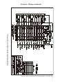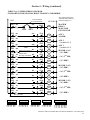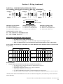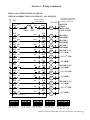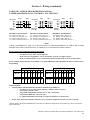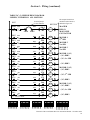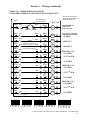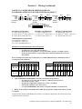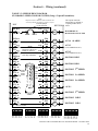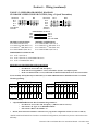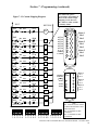
1
Telemotive TR12 inteleSmart™ Receiver Radio Control Equipment Instruction Manual TCTR12-PDA Rev. L November 2014 Part Number 30033T ©Copyright 2014 Magnetek Material Handling Table of Contents Service Information .....................................................................................................1 Radio Controlled Crane Safety...................................................................................2 General System Information.....................................................................................11 Installation ..................................................................................................................13 Operation ....................................................... See Appropriate Transmitter Manual Wiring .........................................................................................................................18 Programming..............................................................................................................45 RCP Programming ....................................................................................................63 Servicing......................................................................................................................72 Spare Parts .................................................................................................................77 Telemotive TR12 inteleSmart Receiver Instruction Manual – November 2014 Section 1 – Service Information Your New Radio Receiver Thank you for your purchase of Magnetek’s Telemotive® brand TR 12 inteleSmart Receiver. Magnetek has set a whole new standard in radio-remote performance, dependability, and value with this unique line of products. Without a doubt, our Telemotive TR 12 inteleSmart Receiver is the ultimate solution for having precise, undeterred, and safe control of your material. If your product ever needs modification or service, please contact one of our representatives at the following locations: U.S. Service Information For questions regarding service or technical information, contact: 1-866-MAG-SERV (1-866-624-7378). Magnetek Material Handling N49 W13650 Campbell Drive Menomonee Falls, WI 53051 Telephone: +1.800.288.8178 Website: e-mail: www.magnetek.com [email protected] Fax Numbers Main: +1.800.298.3503 Sales: +1.262.783.3510 Service: +1.262.783.3508 Canada Service Information: 4090B Sladeview Crescent Mississauga, Ontario L5L 5Y5 Canada Phone: +1.800.792.7253 Fax: +1.905.828.5707 Telemotive TR12 inteleSmart Receiver Instruction Manual – November 2014 1 Section 2 - Radio Controlled Crane Safety Telemotive Industrial Control trademarks: Boommate, GateMate, 10K, inteleSmart, Telemotive, telePilot, telePendant, Laser Guard, Teledrive, Teltec, and TeleMotion are either trademarks or registered trademarks of Telemotive Industrial Controls. Third-party trademarks: All other trademarks, trade names or company names referenced herein are used for identification only and are the property of their respective owners. CAUTION ONLY TRAINED QUALIFIED INDIVIDUALS SHOULD DO SERVICING. STRICT ANTI-STATIC HANDLING PROCEDURES MUST BE FOLLOWED. FAILURE TO FOLLOW THIS CAUTION COULD RESULT IN SERIOUS DAMAGE TO EQUIPMENT AND/OR VOID THE WARRANTY. Warnings, Cautions And Notes. Throughout this document WARNING, CAUTION and NOTE statements have been deliberately placed to highlight items critical to the protection of personnel and equipment. WARNING – A warning highlights an essential operating or maintenance procedure, practice, etc. which if not strictly observed, could result in injury or death of personnel, or long term physical hazards. Warnings are highlighted as shown below: WARNING CAUTION – A caution highlights an essential operating or maintenance procedure, practice, etc. which if not strictly observed, could result in damage to, or destruction of equipment, or loss of functional effectiveness. Cautions are highlighted as shown below: CAUTION NOTE – A note highlights an essential operating or maintenance procedure, condition or statement. Notes are shown as below: NOTE WARNINGS, CAUTIONS AND NOTES SHOULD NEVER BE DISREGARDED. The safety rules in this section are not intended to replace any rules or regulations of any applicable local, state, or federal governing organizations. The following information is intended to be used in conjunction with other rules or regulations already in existence. It is important to read all of the safety information contained in this section before installing or operating the Radio Control System. Telemotive TR12 inteleSmart Receiver Instruction Manual – November 2014 2 Section 2 - Radio Controlled Crane Safety (continued) 2-1. Critical Installation Considerations. WARNING ALL EQUIPMENT MUST HAVE A MAINLINE CONTACTOR INSTALLED AND ALL TRACKED CRANES AND SIMILAR EQUIPMENT MUST HAVE A BRAKE INSTALLED. FAILURE TO FOLLOW THIS WARNING COULD RESULT IN SERIOUS INJURY OR DEATH AND DAMAGE TO EQUIPMENT. WARNING ON ALL REMOTE CONTROLLED CRANES AN AUDIBLE AND/OR VISUAL WARNING MEANS MUST BE PROVIDED. THESE AUDIBLE AND/OR VISUAL WARNING DEVICES MUST MEET ALL GOVERNMENTAL REQUIREMENTS. FAILURE TO FOLLOW THIS WARNING COULD RESULT IN SERIOUS INJURY OR DEATH AND DAMAGE TO EQUIPMENT. WARNING REMOVE ALL ELECTRICAL POWER FROM THE CRANE OR MACHINERY BEFORE ATTEMPTING ANY INSTALLATION PROCEDURES. DE-ENERGIZE AND TAG OUT ALL SOURCES OF ELECTRICAL POWER BEFORE TOUCH TESTING ANY EQUIPMENT. FAILURE TO FOLLOW THIS WARNING COULD RESULT IN SERIOUS INJURY OR DEATH AND DAMAGE TO EQUIPMENT. WARNING THE DIRECT OUTPUTS OF THIS PRODUCT ARE NOT DESIGNED TO INTERFACE DIRECTLY TO TWO STATE SAFETY CRITICAL MAINTAINED FUNCTIONS, I.E., MAGNETS, VACUUM LIFTS, PUMPS, EMERGENCY EQUIPMENT, ETC. A MECHANICALLY LOCKING INTERMEDIATE RELAY SYSTEM WITH SEPARATE POWER CONSIDERATIONS MUST BE PROVIDED. FAILURE TO FOLLOW THIS WARNING COULD RESULT IN SERIOUS INJURY OR DEATH AND DAMAGE TO EQUIPMENT. Telemotive TR12 inteleSmart Receiver Instruction Manual – November 2014 3 Section 2 - Radio Controlled Crane Safety (continued) 2-2. General. Radio controlled overhead cranes and other material handling equipment operate in several directions. They are large, bulky pieces of equipment that handle heavy loads efficiently at high speeds. Quite frequently, the equipment is operated in areas where people are working on the floor below. The crane operator must exercise extreme caution at all times. Workers must constantly be alert to avoid accidents. The following rules have been included to indicate how careful and thoughtful actions may prevent injuries, damage to equipment, or even save a life. If radio controlled material-handling equipment is operated from the cab, special care must be taken to secure the transmitter. Refer to section titled Section 2-9. Boarding The Crane for specific safety rules. 2-3. Persons Authorized To Operate Radio Controlled Cranes. Only properly trained persons designated by management should be permitted to operate radio-controlled cranes. Radio controlled cranes should not be operated by any person who cannot read or understand signs, notices and operating instructions that pertain to the crane. Radio controlled cranes should not be operated by any person with insufficient eyesight or hearing or by any person who may be suffering from a disorder or illness or is taking any medication that may cause loss of crane control. 2-4. Training Checklist For Crane Operators. Anyone being trained to operate a radio-controlled crane should possess as a minimum the following knowledge and skills before operating the crane: The operator should have knowledge of hazards peculiar to crane operation. The operator should have knowledge of the safety rules for radio-controlled cranes. The operator should have the ability to judge distance or moving objects. The operator should have knowledge of the radio transmitter. The operator should know the limit switch test procedure. The operator should know, where authorized, instructions for plugging motions. The operator should have knowledge of the use of crane warning lights and alarms. The operator should have knowledge of observing crane signal lights. The operator should be trained to avoid striking any obstructions. The operator should have knowledge of the proper clearance of lifts or hooks before moving bridge or trolley. The operator should have knowledge of the proper storage space for radio transmitter when not in use. The operator should be trained in transferring radio transmitter to another person. The operator should be trained how and when to report unsafe or unusual operating conditions. The operator should be trained how to exhibit caution in approaching bridge or trolley bumpers. The operator should know equipment capacity. Telemotive TR12 inteleSmart Receiver Instruction Manual – November 2014 4 Section 2 - Radio Controlled Crane Safety (continued) The operator should be trained in making lifts below floor level. The operator should be trained in making side pulls. The operator should know how to keep himself and other people clear of lifts and to avoid "pinch" points. The operator should know cable and hook inspection procedures. The operator should know procedures for testing hoist, trolley, and bridge brakes. 2-5. Operating Area. Aisles between equipment, stock, etc., should be free of obstructions so the crane operator can move freely. These aisles should be a minimum of three feet (one meter) wide, or meet local regulations. Crane operators should always position themselves for the best view of the crane they are controlling. The crane should never be operated blindly. The operator should stay as close to the crane load as possible. Operators should never position themselves in a "pinch" point. 2-6. Transmitter Unit. Transmitter switches should never be mechanically blocked ON or OFF for any crane motion. When not in use turn the transmitter OFF. A secure storage space should be provided for the transmitter unit and the transmitter unit should always be placed there when not in use. This precaution will prevent unauthorized people from operating the crane. Spare transmitters should be stored in a secure storage space and only removed from the storage space after the current transmitter in use has been turned OFF, taken out of the service area and secured. Before putting the transmitter in service the transmitter unit should be inspected for any damage or excessive wear. Units with, but not limited to, any of the following: broken housings, switches or handles, missing battery doors, switch boots or switch knobs should be repaired before putting into service. 2-7. Operating The Crane. 2-7.1. Pre-operation Test. At the start of each work shift, or when a new operator takes control of the crane, operators shall do as a minimum the following steps before making lifts with any crane or hoist: Test the upper-limit switch. Slowly raise the unloaded hook block until the limit switch trips. When checking limit switches the hoist should be centered over an area free of personnel and equipment. Visually inspect the hook, load lines, trolley, and bridge as much as possible from the operator's station; in most instances, this will be the floor of the building. The bridge and trolley brakes should be tested. On transmitter units equipped with two or more speeds, use the "lowest" speed when testing braking devices. When lifting maximum loads, the crane operator should test the hoist brakes by raising the load a few inches from the floor. If the brakes do not hold, the load should immediately be lowered to the floor. If provided, test the lower-limit switch. Test all warning devices. Test all direction and speed controls for both bridge and trolley travel. Telemotive TR12 inteleSmart Receiver Instruction Manual – November 2014 5 Section 2 - Radio Controlled Crane Safety (continued) Test all bridge and trolley limit switches, where provided, if operation will bring the equipment in close proximity to the limit switches. Test the transmitter emergency stop. Test the hoist brake to verify there is no drift without a load. If any crane or hoist fails any of the above tests notify the supervisor and lock out and tag for repair. 2-7.2. General Rules For Operation. Consult the crane manufacturer, local and governmental regulations for complete rules of operation. In general the following rules apply to remotely controlled cranes: The limit switches should never be used as a regular stopping device. They are intended to be protective devices. Do not make lifts in excess of the equipment rated capacity. The bridge and trolley should be centered directly over the load when the load is raised to prevent swinging when making lifts. A crane designed for this purpose and only with supervisor permission should make side pulls. When a lift is being made, the crane operator should not be positioned in the line of travel. The crane or hoist should be operated from a position either to the side or opposite from the direction of travel. When raising or lowering a load, proceed slowly and make certain the load is under control. Tag lines should be used for handling unusual lengths or bulky loads. Remove slack from chains or slings gradually. Make certain all personnel are clear before making a lift. The crane operator should keep all body parts away from the lift and should never be positioned under the lift. Do not make a lift or move a load if anyone is in a location where they could be struck by the crane or the load. If the crane operator is being helped, the crane should not be moved until the helper signals they are clear of the crane and its load. When a load is hanging from the crane hook and the crane is being moved, the crane operator should sound all warning devices frequently. Loads should not be carried over workers heads. If a worker is in the path of crane travel, the crane operator should stop the crane and clear the area before proceeding. Runway stops or other cranes should never be bumped into. When moving the crane, the crane operator should be sure that the hook block and attachments or cables would not catch on nearby equipment. Slings, chains, or cables should never be dragged along the floor. Unless required for operator safety, gloves should not be worn when operating the transmitter unit. All loose materials or parts should be removed from the load before starting the lift. The crane operator should always hoist lifts high enough to clear all equipment and workers. The crane operator should never permit anyone to ride on the load or hook except when authorized by the supervisor. When another crane on the same runway is stationary with a load hanging, the crane operator should maintain a safe distance between the stationary crane and the one under their control. Telemotive TR12 inteleSmart Receiver Instruction Manual – November 2014 6 Section 2 - Radio Controlled Crane Safety (continued) Never leave suspended loads unattended. In an emergency, if the crane is inoperative and a load suspended, notify the supervisor immediately, barricade and post signs on the floor beneath crane and load. If power to the crane is removed, the crane operator should turn the transmitter unit OFF and keep it OFF until power is restored. If the crane fails to respond properly, the crane operator should stop operation, turn the transmitter unit OFF and immediately report the condition to their supervisor. Outdoor cranes, which are subject to movement by wind, should be securely anchored when left unattended. If the crane is equipped with bridge brakes, the parking brake should be set immediately. 2-8. Boarding The Crane. The crane should not be boarded without permission of the supervisor. The crane operator should turn off the transmitter and take it with them when boarding the crane. If more than one person is boarding the crane, one person should be made responsible for ensuring all personnel are off the crane before the system is returned to operation. 2-9. Crane Maintenance And Repair. Qualified personnel must maintain a regularly, i.e., such as monthly, scheduled crane inspection. During this crane inspection the functionality and safety of the crane remote control must also be tested. The inspection shall include, but be not limited to items listed in Section 2-12 Condition Of The Radio Controlled Crane. Consult crane manufacturer, local and governmental regulations for recommended inspection intervals and proper inspection procedures. Problems noted during this inspection must be repaired before using the crane or the remote control. Minor repairs include routine maintenance and repairs such as greasing, cleaning and control troubleshooting. All other repairs should be considered major. If the repair crew consists of more than one person, one person should be designated as the repair crew leader with the following responsibilities. If the repair crew consists of only one person, that person has the following responsibilities: For minor repairs warning signs should be placed on the floor beneath the crane or suspended from the crane. For major repairs, the floor area below the crane should be roped off. When major repairs are to take place, all persons operating other cranes on the same or adjacent runways, if any, must be notified prior to starting repairs. Notification should include the nature of the repair, safeguards provided, and movement limitations while repairs are in progress. When practical, radio controlled cranes which cannot be moved during repairs must be protected against being bumped by other cranes on the runway. Bumpers should be installed on the exposed side or sides of the crane under repair. They should be placed as far away as possible. The location of these bumpers should be indicated by red lights placed so that they are clearly visible to other crane operators traveling on the same runway. When it is not possible to use bumpers, red lights must be placed so they are clearly visible to other crane operators traveling on the same runway to indicate the restricted travel zone. All crane operators on the same runway must be informed of the repair effort and thoroughly instructed to what their operations are limited to and informed they will be notified when repairs are completed. If any hazard involving the repairperson exists when there is a runway adjacent to the crane under repair, the adjacent runway should be blocked off as described above. When it is necessary to continue crane operation on the adjacent runways warning lights must be installed and be visible to operators of cranes on those runways. All cranes should come to a complete stop prior to entering the restricted area and should proceed through this area only after receiving permission from a signal person designated for this purpose. Access of persons to and from the crane being repaired should be under control of the repair crew leader. Telemotive TR12 inteleSmart Receiver Instruction Manual – November 2014 7 Section 2 - Radio Controlled Crane Safety (continued) When boarding the crane, the transmitter should be turned OFF and the transmitter should remain with the repair crew leader. The leader should board the crane first, open and lock out the main switch, and then signal the other members of the crew it is safe to board the crane. If work on the crane is to be done in areas not protected by standard handrails, the repair crew should wear approved safety belts. All tools and equipment should be moved onto the crane by the use of hand lines. The tools and equipment should be adequately secured to the hand lines. If it is necessary to have the crane control circuits energized, all power circuits for crane movement must be opened prior to energizing the control circuits. All personnel and tools should be moved to a safe spot before moving the crane during repairs. Headroom is at a minimum in some crane cabs and on some crane walkways. Caution should be exercised when boarding or working on cranes. Hard hats should be worn whenever possible. When repairs are finished, all personnel, tools and repair equipment should be removed before energizing the crane circuits. 2-10. Using The Crane As A Work Platform. When the crane is to be used as a stationary work platform, follow all rules provided in Section 2-8 Crane Maintenance and Repair. When it is necessary for the crane to be moved from time to time, the crane operator should board the crane with the transmitter unit. The crane operator should ensure all personnel working on the crane are in a secure position before moving the crane to the next workstation. It should also be the crane operator’s responsibility to ensure the main switch is open and locked down before work is resumed. WARNING THE CRANE OPERATOR SHOULD NOT ATTEMPT TO REPAIR ANY OF THE ITEMS STATED BELOW. THE CRANE CONDITION SHOULD BE REPORTED TO THE SUPERVSOR. FAILURE TO FOLLOW THIS WARNING COULD RESULT IN SERIOUS INJURY OR DEATH AND DAMAGE TO EQUIPMENT. 2-11. Condition Of The Radio Controlled Crane. If the crane fails to respond properly, the crane operator(s) should notify their supervisor. When serious conditions are noticed (conditions that make the crane unsafe to operate), the crane should be shut down immediately and the supervisor notified. The following is a list of some of the items that should be included in the report (see the crane manufacturer for specifics and possible additional items): Condition of hoisting cable and hook block (broken strands, clipped sheave wheels, etc.). Condition of brakes (hoist, trolley, and bridge). (No bluing, rivets on shoes showing, glazing, etc.). Condition of trolley and rail stops. Condition of bridge structure. Condition of festoon system. Broken welds in any part of the crane structure. Telemotive TR12 inteleSmart Receiver Instruction Manual – November 2014 8 Section 2 - Radio Controlled Crane Safety (continued) Proper fluid levels and lubrication. Condition of bridge and trolley stops. Carbon dust or signs burning on the covers of motors. Indication of fluid, oil or grease leaks. Condition of rail sweeps. Walkways required handrails and ladders are in place, sturdy and not loose. Protective guards are in place for all moving parts. Alignment of bridge (screeching or squealing wheels indicate bridge is out of line). Broken, cracked, or chipped rails on trolley or runway. Condition of limit switches. Condition of electrical and mechanical control (electrical or mechanical defects which cause faulty operation such as un-commanded stopping or starting of any crane motions, warning devices, lights, or auxiliary functions). Condition of gears (grinding or squealing may indicate foreign materials in gear teeth or a lack of lubrication). All controls especially ESTOPs are in place and in working order. Frequent relay tripping of power circuits. Mechanical parts loosened by vibration (loose rivets, covers, bolts, etc.). Uneven riding (worn or damaged wheels). Condition of collector shoes or bars. Condition of warning or signal lights and horns (burned out or broken). 2-12. Batteries WARNING KNOW AND FOLLOW PROPER BATTERY HANDLING, CHARGING AND DISPOSAL PROCEDURES. IMPROPER BATTERY PROCEDURES CAN CAUSE BATTERIES TO EXPLODE OR DO OTHER SERIOUS DAMAGE. FAILURE TO FOLLOW THIS WARNING COULD RESULT IN SERIOUS INJURY OR DEATH AND DAMAGE TO EQUIPMENT. Telemotive TR12 inteleSmart Receiver Instruction Manual – November 2014 9 Section 2 - Radio Controlled Crane Safety (continued) 2-12.1. Battery Handling. Use only batteries approved by Telemotive for the specific product. Do not dispose of a battery pack in fire; it may explode. Do not attempt to open the battery pack. Do not short circuit battery. Do not attempt to use a battery that is leaking, swollen or corroded. For intrinsically safe environments only use specified Telemotive intrinsically safe batteries. Keep the battery pack environment cool during charging operation and storage (i.e., not in direct sunlight or close to a heating source). 2-12.2. Battery Charging. For those transmitters equipped with battery chargers, please familiarize all users with the instructions of the charger before attempting to use. Use only Telemotive approved chargers for the appropriate battery pack. Do not attempt to charge non-rechargeable battery packs. Avoid charging the battery pack for more than 24 hours. Do not charge batteries in a hazardous environment. Do not short the charger. Do not attempt to charge a damaged battery. Charger units are not intended for outdoor use. Use only indoors. 2-12.3. Battery Disposal. Before disposing of batteries consult local and governmental regulatory requirements for proper disposal procedures. Telemotive TR12 inteleSmart Receiver Instruction Manual – November 2014 10 Section 3 - General System Information 3-1. General System Information. The Telemotive Radio Control System (system) provides remote control of overhead cranes using radio signals. The system consists of a hand held portable battery operated transmitter unit and a fixed station receiver unit. A unique 16-bit code (Access Code) for each system is preset in every transmitter and receiver. The receiver considers any received signal which does not match the receiver access code setting invalid. The Access Code is made up of 16-bits (65,000 combinations) and no two similar codes are assigned to any two Telemotive systems. Up to four systems may be used with the same frequency in a 600-foot area (220 meters). Each transmitter operating on the same frequency may be operated in close proximity, not less than six feet (1.9 meters) to each other. 3-2. TMS Low Power Signaling. TMS (Time Multiplexed Signaling) is a Telemotive proprietary high-speed packet data system. The system software is structured to minimize "on the air" transmission time of any transmitter. This allows for multiple transmitters to share a common frequency. The TMS system is designed so that a transmitter will send a signal for a predetermined ON time, and then will turn OFF. The length of transmitter ON time is referred to as data burst or packet. The packet length is a function of the quantity of data to be sent and the data rate (baud). Once the packet is sent, the transmitter will turn OFF. This allows for other transmitters to time-share the same frequency when a transmitter has turned OFF. The TMS system software determines the OFF period and repetition rate of the ON period. Since each system has its own access code, up to 4 transmitters can share and have equal access to the same frequency. TMS also allows for reduced battery consumption and extended battery life. These systems have low power pulsed signaling, FCC certified under Part 15 Telecommunications Code of Regulations, no license is required. The transmitter unit is frequency modulated, low power and is certified under the appropriate regulations. A license is not required for the transmitter or operator. Modifications to the RF section of this system are not permitted and could void FCC certification. 3-3. Channel Designations: Indicator Count Channel Designator 01. 02. 03. 04. 05. 06. 07. 08. 09. 10. 11. 12. 13. 14. 15. 16. AK01 AK02 AK03 AK04 AK05 AK06 AK07 AK08 AK09 AK10 AK11 AK12 AK13 AK14 AK15 AK16 Actual Frequency 439.8 MHz 439.6 MHz 439.4 MHz 439.2 MHz 439.0 MHz 438.8 MHz 438.6 MHz 438.4 MHz 438.2 MHz 438.0 MHz 437.8 MHz 437.6 MHz 437.4 MHz 437.2 MHz 437.0 MHz 436.8 MHz Indicator Count Channel Designator 17. 18. 19. 20. 21. 22. 23. 24. 25. 26. 27. 28. 29. 38. 50. AK17 AK18 AK19 AK20 AKA00 AKA01 AKA02 AKA03 AKA04 AKA05 AKA06 AKA07 AKA08 AK38 AK50 Actual Frequency 436.6 MHz 436.4 MHz 436.2 MHz 436.0 MHz 433.125 MHz 433.325 MHz 433.525 MHz 433.725 MHz 433.925 MHz 434.125 MHz 434.325 MHz 434.525 MHz 434.725 MHz 432.4 MHz 430.0 MHz Telemotive TR12 inteleSmart Receiver Instruction Manual – November 2014 11 Section 3 - General System Information (continued) 3-4. Receiver Specifications. Receiver housing: NEMA 4X, IP67 Operating Temperature: –22° F to +158° F (-30 degrees C to +70 degrees C) ambient. Humidity: up to 95 % (non-condensing). Typical Operating Range: 300 feet (91 meters). Relays are rated for 16 Amps 277VAC/24VDC, 1 HP 240VAC for maximum life and surge protection; they are fused with 2AG Slow Blo fuses and protected with MOVs. 3-5. Receiver Unit. The receiver unit consists of a synthesized RF module, antenna, integral power supply, microprocessor controlled output motor control and auxiliary function relays and mainline contactor relay. The receiver unit contains circuitry, which matches the frequency and access code of the transmitter. Telemotive TR12 inteleSmart Receiver Instruction Manual – November 2014 12 Section 4 - Installation 4-1. Pre-Installation Considerations. To ensure reliable and safe operation of the system, the following items must be considered before installing the receiver unit. WARNING THE RECEIVER UNIT OR RELAYS ARE NOT RATED AS EXPLOSION PROOF. THE RECEIVER UNIT MUST NOT BE INSTALLED IN EXPLOSIVE ENVIRONMENTS UNLESS APPROPRIATE SECONDARY ENCLOSURE MEASURES ARE TAKEN. FAILURE TO FOLLOW THIS WARNING COULD RESULT IN SERIOUS INJURY OR DEATH AND DAMAGE TO EQUIPMENT. 4-2. Receiver Unit Mounting Location Considerations. Ensure the mounting location is as far as possible from exposed trolley wires and sources of electromagnetic or radiated noise The receiver cabinet is approximately 8" (20 cm) wide by 12" (30 cm) high. A depth of at least 13" (35 cm) must be provided to allow the cabinet door to open. The mounting surface must be smooth and continuous. Mounting the cabinet on uneven surfaces could cause warpage or stress internal components. The receiver unit may be mounted in any position. The greatest radio control range is obtained when the receiver unit is mounted with the antenna at the top. If possible, avoid installing receiver unit to a surface where high vibration or shock is present. If this cannot be avoided, use appropriate shock mounts. 4-3. Antenna Mounting Considerations. It is best to mount the antenna so that it is visible to the operator. Usually, this is accomplished by mounting the antenna under the crane and pointed down. You should always try and avoid power sources, motors, drives, brakes, etc. If necessary we offer an external antenna kit. 4-4. Line Input Considerations. WARNING THE UNIT MUST BE WIRED TO THE CORRECT VOLTAGE, AND BE CONNECTED TO THE CORRECT TERMINAL AS REQUIRED BY THE ACTUAL LINE VOLTAGE. FAILURE FOLLOW THIS WARNING COULD RESULT IN SERIOUS INJURY OR DEATH AND DAMAGE TO EQUIPMENT. The receiver unit has direct connect provisions for operation from 115 VAC (nominal), 60 Hz power. For applications where the line voltage is not between 95-130 VAC or if 260 VAC or 440 VAC power is used, a step up or step down transformer must be used. Telemotive TR12 inteleSmart Receiver Instruction Manual – November 2014 13 Section 4 – Installation (continued) NOTE THE RECEIVER UNIT SHOULD NOT BE CONNECTED TO LINES CONTAINING EXCESSIVE POWER UP TRANSIENTS OR CONTINUOUS COMMUTATOR NOISE. A LINE CONDITIONER MAY BE NECESSARY IN SOME INSTALLATIONS. 4-5. Wiring Considerations. 1. Read this manual before installation. 2. Please observe appropriate local and National Electrical Codes when wiring electrical devices. 3. Do not connect or disconnect wiring, or perform circuit checks while the power is turned on. 4. The motor wiring should be in a separate metal conduit from the power wiring, which should also be in metal conduit. 5. Low voltage wires shall be wired with proper low voltage class wiring procedures. 6. Control wiring as well as antenna wiring shall be in separate conduit and shall be kept as short as possible. 7. All terminals shall be tightened to specified terminal torque 4.4 IN-LBS (.5 N·m) unless otherwise specified. 8. Remove excess metal screws, metal filings and wire clippings from inside of unit. 9. Inspect to make sure no exposed wire has contact with any other wiring or terminals. 10. Suppressors are strongly recommended on all contactors. 4-6. Receiver/Equipment Interface Considerations. All output relay contacts are rated for 16 Amps 277VAC/24VDC, 1 HP 240VAC for maximum life and surge protection; they are fused with 2AG Slow Blo fuses and protected with MOVs. Connection to equipment or contactors with higher voltage or current requirements will require intermediate relays. All relay outputs are normally open, momentary contact. Since a relay closure is only active while the transmitter unit key is pressed and held, devices such as lights or lifting magnet must use a mechanical auxiliary latching relay. 4-7. Receiver Unit Cabinet Mounting. See Figure 4-2. Receiver Mounting Details. Allow room in mounting the receiver for the door to swing open. Mount receiver unit cabinet securely to mounting surface. Actual cabinet mounting dimensions are shown on Figure 4-2. Receiver Mounting Details. Telemotive TR12 inteleSmart Receiver Instruction Manual – November 2014 14 Section 4 – Installation (continued) 4-8. Receiver Installation. NOTE CONNECTING OUTPUTS TO DRIVES. MOVS (TRANSIENT PROTECTORS) ARE ON ALL THE OUTPUT RELAYS TO PROTECT THE RELAYS FROM POWER SURGES. MOVS ALLOW A SMALL LEAKAGE CURRENT THAT CAN AFFECT SOME HIGH IMPEDANCE CIRCUITS. WHEN CONNECTING OUTPUT RELAYS TO DRIVES, IT MAY BE REQUIRED TO REMOVE THE MOV TO PREVENT THE LEAKAGE CURRENT THROUGH THE MOV FROM HOLDING IN THE DRIVE. SEE FIGURE 8-1. RECEIVER LAYOUT FOR THE LOCATION OF THE MOVS. THE MOVS ARE NEXT TO THE RELAYS THEY PROTECT. THE MOVS CAN BE CUT OUT OF THE CIRCUIT WITH A WIRE CUTTER. REMEMBER TO DO THIS WITH ALL POWER OFF ON THE CRANE AND ALL ASSOCIATED CONTROLS. 1. Normally it should not be necessary to set the Access Codes; they are preset. If special field programming is needed, power the unit up on the bench and pre-program the unit for any special crane configurations or other parameters, if desired; see Section 7 - Programming for details. The unit can be re-programmed after it is installed as well. 2. Position the receiver. Locate as far as possible from exposed trolley wire and sources of electromagnetic or radiated noise. Cabinet mounting dimensions and mounting template is on next page see Figure 4-2. Receiver Mounting Details. Antenna should be kept as clear as possible of any metal object. 3. Mount the receiver. The four deep mounting holes in corners of the receiver use quantity four #1024 combo drive round head screws 1.5” in length, four #10 lock washers and four #10-24 hex nuts to mount. Lock washers should be used in front of hex nuts. 4. Wire the unit using the appropriate electrical drawings for the specific transmitter and crane orientation selected - see Section 6 - Wiring. If you need to remove the main board (4 screws) the antenna unplugs from the RF Receiver, be sure to dress the antenna cable on the RF Receiver when reinstalling the antenna cable. 5. Wire the power to J1 input power connector. The connections are Ground (GND), Neutral (N), and 115 VAC 60 Hz (115V). See Figure 4-1. Input Power Connections. 6. Wiring of the system should now be complete. Install antenna. 7. Turn switch SW2 OFF (MR relay control) and SW1 ON (main power switch). Stand clear of the crane and apply AC power to receiver unit. Check to see if at least the three green LEDs (DS1, DS2 and DS3) are ON, as well as two green LEDs on the RX module (other LEDs may be ON also). If none are lit check AC power and power switch SW1. See Figure 8-1. Receiver Layout for switch and LED locations. Telemotive TR12 inteleSmart Receiver Instruction Manual – November 2014 15 Section 4 – Installation (continued) J1 1 120V N GRN Figure 4-1. Input Power Connections. 7.09” 180 mm .30” DIA. 7.5 mm hole 4 places 7.87” 200 mm 11.02” 279.9 mm 11.81” 300 mm Drawing not to scale. Overall Cabinet Depth Cabinet With door closed inches 5.26 With door closed mm 133.60 With door open inches 12.12 With door open mm 307.98 Figure 4-2. Receiver Mounting Details NOTE WHEN FIRST APPLING POWER TO THE UNIT YOU MUST WAIT 10 SECONDS FOR THE RECEIVER TO GO THROUGH THE PROGRAMMING MODE. 8. Wait 10 seconds and turn the transmitter ON. Check to see if the red LEDs DS30 and DS32 are now ON. At this point the MR relay is disabled; the functions of the transmitter can be checked by noting the turning ON of the appropriate red LEDs next to the control relays (K1-K12). After checking out the functions, turn switch SW2 ON to enable the MR relay (red LED DS31 should now turn ON), check function and direction by jogging each motion. Installation should now be complete. 9. If there are any problems see Section 8 - Servicing. Telemotive TR12 inteleSmart Receiver Instruction Manual – November 2014 16 Section 5 See Appropriate Transmitter Manual Telemotive TR12 inteleSmart Receiver Instruction Manual – November 2014 17 Section 6 - Wiring 6-1. Wiring Diagrams. The system comes pre-programmed; the following pages in this section have individual wiring diagrams for different crane configurations. Find the appropriate wiring diagram and if necessary program the receiver and transmitter switch settings shown for the appropriate diagram. Terminal designators are marked on the wiring diagram corresponding to designators found on the Receiver Board. For terminal locations see Figure 8-1. Receiver Layout. After selecting the appropriate motors for each function remember to place the appropriate label on your transmitter for describing the appropriate command. Typically in the following wiring diagrams, the Hoist is shown as Motor 1, Trolley as Motor 2, and Bridge is shown as Motor 3. Make sure the transmitter is labeled with the correct functions. Stick-on or movable button labels are provided with the transmitter for proper labeling. 6-2. Installation. Follow the procedure in Section 4 - Installation for installing the receiver. 6-3. Alarms And Horns. Make sure that the installation includes the proper alarms, horns, indicator lights and their associated controls as required by local and governmental regulations. 6-4. Relay Sequencing. The Diagrams in this section show actual relay sequencing. Typically the directional stays in when the second and third speed is actuated. 6-5. Alarm After ESTOP. This is only for wiring configurations where the Aux 3 (relay K12, output J8-6) is being used for the Alarm function, placing a jumper on JU1 on the Receiver Board will allow the alarm to function after an ESTOP command. See Figure 8-1. Receiver Layout for jumper location. 6-6. Connecting Outputs To Drives. MOVs (transient protectors) are on all the output relays to protect the relays from power surges. MOVs allow a small leakage current that can affect some high impedance circuits. When connecting output relays to drives, it may be required to remove the MOV to prevent the leakage current through the MOV from holding in the drive. See Figure 8-1. Receiver Layout for the location of the MOVs. The MOVs are next to the relays they protect. The MOVs can be cut out of the circuit with a wire cutter. Remember to do this with ALL power OFF on the crane and all associated controls. 6-7. Single-Speed Transmitter Wiring. For a Single-Speed Transmitter the only wiring configuration is the diagram in Section 6 - Wiring. Table 1, Single-Speed Standard Configuration Hoist, Trolley and Bridge. 6-8. 2-Speed and 3-Speed telePendant operation. A 3-Speed telePendant will work on a 2-Speed receiver; the 3rd speed position (switch detent) on the motion buttons will not activate any functions or speed changes. To use a 3-Speed telePendant on a 2Speed receiver the particular transmitter Bank to be used must have matching frequency, Access Codes and its Tx Type” set to “3 SPD telePendant”. For the 3-Speed telePendant transmitter there are no configuration switches to set; the default for the configuration switches is all OFF. The number of Motors must be selected. Telemotive TR12 inteleSmart Receiver Instruction Manual – November 2014 18 Section 6 – Wiring (continued) 6-9. Commons. Each receiver relay output (normally open) is independent (floating) both input and output. Relay commons (Hot) are not wired together on the Receiver Board nor connected to the input power. Relay common wiring must be provided. This is to give total flexibility. Different motors and/or functions can use different phases or independent (even DC) power sources. 6-10. Power or Hot routing. The Diagrams in this Section show independent power “HOT” routed to each relay. An alternate way of routing power is to route all power to each function from the MR (Master Relay) relay. This wiring can only be used if the total current does not exceed the MR relay ratings. Telemotive TR12 inteleSmart Receiver Instruction Manual – November 2014 19 Section 6 - Wiring (Continued) 6-11. Legend. The following is the legend for the wiring diagrams below: # # K# C# An input with the terminal number # matching the connector in the receiver. An output with the terminal Customer supplied number # matching the con- contactor coil with arc suppressor in parallel. nector in the receiver. Matching relay contacts in radio receiver panel by number. Figure 6-1. Legend. ON/OFF & Low Battery Indicators Motor 1 Dir 1 ON/ OFF Auxiliary Controls ON/ OFF Motor 2 Dir 1 Dir 2 TROLLEY AUX 1 AUX 2 Auxiliary Controls Motor 3 Dir 1 BRIDGE Dir 2 AUX 3 A TX12M-2 A AUX 1 AUX 2 AUX 3 AUX 4 AUX 5 AUX 6 Motor 1 Dir 1 Dir 2 HOIST* 2-Speed telePilot HOIST* Motor 2 Dir 1 Dir 2 Motor 3 Dir 1 Dir 2 TROLLEY* BRIDGE* B E-STOP E-STOP B Optional 4th Motor or Select Indicators Dir 2 Programmable Motor Control and Select Indicators 2-Speed telePendant *NOTE: Hoist, Trolley and Bridge are listed here as traditional configurations; the installer may choose to define the motors differently. Figure 6-2. telePilot and telePendant, Output Controls Telemotive TR12 inteleSmart Receiver Instruction Manual – November 2014 20 Section 6 - Wiring (continued) Wiring for Internal Transfer Switch using Optional Pigtail. Telemotive TR12 inteleSmart Receiver Instruction Manual – November 2014 21 Wiring for External Transfer Switch using Optional Pigtail. Section 6 - Wiring (continued) Telemotive TR12 inteleSmart Receiver Instruction Manual – November 2014 22 Section 6 - Wiring (continued) TABLE 1. SINGLE-SPEED WIRING DIAGRAM. STANDARD CONFIGURATION HOIST, TROLLEY AND BRIDGE Note: Move jumper JU1 on the Receiver Board for Alarm after an E-Stop command to function. See Figure 8-1. Receiver Layout for Jumper JU1 location and position. External jumper in J10 connector HOT J10-2 F14 K13 J10-4 J9-5 J9-3 J9-1 J8-5 J8-3 J8-1 J7-5 J7-3 J7-1 J6-5 J6-3 J6-1 F13 K11 F11 K10 F10 K9 F9 K8 F8 K7 F7 K6 F6 RETURN J10-3 MLC MASTER RELAY MAIN LINE CONTACTOR C12 2(Alarm, optional) C11 1(latchable Rx S2-3) C10 3(latchable Rx S2-2) C9 7 C8 4 C7 8 C6 9 C5 5 J10-5 K12 F12 The numbers on the SingleSpeed outputs match the respective numbers on telePilot function buttons K5 J9-6 J9-4 J9-2 J8-6 J8-4 J8-2 J7-6 J7-4 ON/ OFF 7 6 8 5 9 4 10 3 11 2 12 1 E-STOP F5 K4 F4 K3 F3 K2 F2 K1 J7-2 C4 10 C3 11 C2 6 C1 12 J6-6 J6-4 J6-2 telePilot SingleSpeed transmitter Receiver Panel J10-8 J10-7 J10-6 J10-5 J10-4 J10-3 J10-2 J10-1 J9-6 J9-5 J9-4 J9-3 J9-2 J9-1 J8-6 J8-5 J8-4 J8-3 J8-2 J8-1 J7-6 J7-5 J7-4 J7-3 J7-2 J7-1 J6-6 J6-5 J6-4 J6-3 J6-2 J6-1 Telemotive TR12 inteleSmart Receiver Instruction Manual – November 2014 23 Section 6 - Wiring (continued) TABLE 1. SINGLE-SPEED PROGRAMMING DIAGRAM. STANDARD CONFIGURATION HOIST, TROLLEY AND BRIDGE NOTE For details on transmitter switch pair interlocks see telePilot manual programming section, Section 5-3.4.3 SingleSpeed 10K telePilot Lockout Modes on Mode options available in the telePilot transmitter and how they control pushbutton interlocks for the Single-Speed telePilot. Latching outputs: Two latching outputs are available: Output 1, which is set by RX Status Word switch S2-3. Output 3, which is set by RX Status Word switch S2-2. RECEIVER And SINGLE TRANSMITTER SWITCH SETTINGS In the Receiver use the PDA Receiver Programmer to: o Set “Receiver access code” and “Frequency”. o In the “Receiver Programmer” screen, select under “System” “12 output 1 speed”. o In the “Set Status Words” screen, set RX and TX Status Word Switches S1 to S4 as shown below: Xs are normally OFF (0) but may be turned ON (1) to enable additional features detailed in Section 7-11 Status Word Programming. Switch # 1. 1 2 Position 3 4 5 6 7 8 Switch # 1 2 Position 3 4 5 6 7 8 Rx S1 X X X 0 1 X X X Rx S2 0 X X 0 0 0 X X Tx S3 0 0 Tx S4 0 0 0 0 0 0 0 0 0 0 0 0 0 0 In the transmitter: Single-Speed telePilot use the PDA Transmitter Programmer to: o Set “Receiver access code” and “Frequency”. (Must be same as receiver). o Select under “Tx Type” to “1 SPD telePilot”. o Select under “System” “10K”. o Select under “Mode” (see below) the number of the desired button interlocks. Modes are: (See telePilot manual for more detail). Mode 1 is top 2 pairs of buttons interlocked both right and left side. Mode 2 is top 3 pair interlocked right side and top pair interlocked left side. Mode 3 has no interlocks. Telemotive TR12 inteleSmart Receiver Instruction Manual – November 2014 24 Section 6 - Wiring (continued) TABLE 2(A) 2-SPEED WIRING DIAGRAM. STANDARD CONFIGURATION HOIST, TROLLEY AND BRIDGE External jumper in J10 connector HOT J10-2 F14 K13 J10-4 J9-5 F13 J8-3 J8-1 J7-5 J7-3 J7-1 J6-5 J6-3 J6-1 J8-6 F8 J8-2 MOTOR 1 (M1) (M1) DIR 1 C8 (M1) 2ND SPD C7 (M1) DIR 2 C6 MOTOR 2 (M2) (M2) DIR 1 C5 (M2) 2ND SPD C4 (M2) DIR 2 C3 MOTOR 3 (M3) (M3) DIR 1 C2 (M3) 2ND SPD C1 (M3) DIR 2 J7-2 K4 J6-6 K3 J6-4 K2 F2 C9 J7-4 K5 F3 AUX 1 (latchable S2-2) J7-6 K6 F4 C10 J8-4 K7 F5 AUX 2 (latchable S2-3) J9-2 K9 Jumper JU1, Receiver Board for Alarm to F9 function after K8 an E-Stop command. F6 C11 J9-4 *Note: F7 AUX 3 ALARM* J9-6 K10 J8-5 F10 C12 J10-5 K11 J9-1 F11 MLC MASTER RELAY MAIN LINE CONTACTOR J10-3 K12 J9-3 F12 RETURN The outputs listed below match the button labels as defined in Figure 6-2. J6-2 K1 Receiver Panel J10-8 J10-7 J10-6 J10-5 J10-4 J10-3 J10-2 J10-1 J9-6 J9-5 J9-4 J9-3 J9-2 J9-1 J8-6 J8-5 J8-4 J8-3 J8-2 J8-1 J7-6 J7-5 J7-4 J7-3 J7-2 J7-1 J6-6 J6-5 J6-4 J6-3 J6-2 J6-1 Telemotive TR12 inteleSmart Receiver Instruction Manual – November 2014 25 Section 6 - Wiring (continued) TABLE 2(A) 2-SPEED PROGRAMMING DIAGRAM. STANDARD CONFIGURATION HOIST, TROLLEY AND BRIDGE Dir 1 OUTPUTS J8-6 J8-4 J8-2 HOIST* MOTOR 1 2ND Dir 2 1ST 1ST Dir 1 OUTPUTS J7-6 J7-4 J7-2 TROLLEY* MOTOR 2 2ND J9-2 J9-4 J9-6 2ND Dir 2 1ST Dir 1 OUTPUTS J6-6 J6-4 J6-2 1ST 2ND BRIDGE* MOTOR 3 2ND Dir 2 1ST 1ST 2ND INDEPENDENT OUTPUTS AUX 1 AUX 2 AUX 3 ALARM MOTOR 1 CONNECTIONS MOTOR 2 CONNECTIONS MOTOR 3 CONNECTIONS J8-6 HOIST UP (HOT J8-5) J8-4 HOIST 2ND SPEED (HOT J8-3) J8-2 HOIST DOWN (HOT J8-1) J7-6 TROLLEY DIR 1 (HOT J7-5) J7-4 TROLLEY 2ND SPD (HOT J7-3) J7-2 TROLLEY DIR 2 (HOT J7-1) J6-6 BRIDGE DIR 1 (HOT J6-5) J6-4 BRIDGE 2ND SPEED (HOT J6-3) J6-2 BRIDGE DIR 2 (HOT J6-1) INDEPENDENT CONNECTIONS J9-2 AUX 1 (HOT J9-1) (LATCHABLE Rx S2-2) J9-4 AUX 2 (HOT J9-3) (LATCHABLE Rx S2-3) J9-6 AUX 3 ALARM (HOT J9-5) RECEIVER And TRANSMITTER SWITCH SETTINGS In the Receiver use the PDA Receiver Programmer to: o Set “Receiver access code” and “Frequency”. o In the “Receiver Programmer” screen, select under “System” “12 output 2 speed”. o In the “Set Status Words” screen, set RX and TX Status Word Switches S1 to S4 as shown below: Xs are normally OFF (0) but may be turned ON (1) to enable additional features detailed in Section 7-11 Status Word Programming. Switch # 1 2 Position 3 4 5 6 Rx S1 X X X 0 0 X X X Rx S2 0 X X 0 0 0 X X Tx S3 X X X 0 0 0 0 0 Tx S4 0 0 0 0 0 0 0 0 7 8 Switch # 1 2 Position 3 4 5 6 7 8 In the transmitter: 2-Speed telePilot and telePendant use the PDA Transmitter Programmer to: o Set “Receiver access code” and “Frequency” (must be same as receiver). o Select under “System” “10K”. o Program the configuration switches S3-5, -6 and -7 to OFF (0). o Select under “Main/Aux” the word “Aux”. o (A 3-Speed telePendant can be used as a 2-Speed transmitter. See Section 6-8). o MLTX, JLTX and SLTX transmitter switch SW4 “D” program the configuration switches 5, 6 and 7 to OFF (0). *NOTE: HOIST, TROLLEY and BRIDGE are listed here as traditional configurations; the installer may choose to define the motors differently. Telemotive TR12 inteleSmart Receiver Instruction Manual – November 2014 26 Section 6 - Wiring (continued) TABLE 2(B) 2-SPEED WIRING DIAGRAM. 2-SPEED with DIRECTIONAL CONTROLS: ALL MOTIONS External jumper in J10 connector HOT J10-2 F14 K13 J10-4 J9-5 F13 J8-3 J8-1 MOTOR 2 DIR1/DIR2 C10 MOTOR 3 DIR1/DIR2 C9 MOTOR 1 (M1) (M1) DIR 1 C8 (M1) 2ND SPD J9-2 J8-6 J8-4 K8 F8 C11 J9-4 K9 F9 MOTOR 1 DIR1/DIR2 J9-6 K10 J8-5 F10 C12 J10-5 K11 J9-1 F11 MLC MASTER RELAY MAIN LINE CONTACTOR J10-3 K12 J9-3 F12 RETURN J8-2 K7 C7 J7-5 F7 J7-6 K6 C6 J7-3 F6 J7-4 K5 C5 J7-1 F5 J7-2 K4 C4 J6-5 F4 J6-6 K3 C3 J6-3 F3 J6-4 K2 C2 J6-1 F2 The outputs listed below match the button labels as defined in Figure 6-2. (M1) DIR 2 MOTOR 2 (M2) (M2) DIR1 (M2) 2ND SPD (M2) DIR 2 MOTOR 3 (M3) (M3) DIR 1 (M3) 2ND SPD J6-2 K1 C1 (M3) DIR 2 Receiver Panel J10-8 J10-7 J10-6 J10-5 J10-4 J10-3 J10-2 J10-1 J9-6 J9-5 J9-4 J9-3 J9-2 J9-1 J8-6 J8-5 J8-4 J8-3 J8-2 J8-1 J7-6 J7-5 J7-4 J7-3 J7-2 J7-1 J6-6 J6-5 J6-4 J6-3 J6-2 J6-1 Telemotive TR12 inteleSmart Receiver Instruction Manual – November 2014 27 Section 6 - Wiring (continued) TABLE 2(B) 2-SPEED PROGRAMMING DIAGRAM. 2-SPEED with DIRECTIONAL CONTROLS: ALL MOTIONS OUTPUTS J8-6 J8-4 J8-2 J9-6 HOIST* MOTOR 1 Dir 1 2ND Dir 2 1ST 1ST Dir 1 OUTPUTS J7-6 J7-4 J7-2 J9-4 2ND TROLLEY* MOTOR 2 2ND 1ST Dir 2 1ST 2ND MOTOR 1 CONNECTIONS MOTOR 2 CONNECTIONS J8-6 J8-4 J8-2 J9-6 J7-6 J7-4 J7-2 J9-4 HOIST UP (HOT J8-5) HOIST 2ND SPD (HOT J8-3) HOIST DOWN (HOT J8-1) HOIST UP/DOWN (HOT J9-5) TROLLEY DIR 1 (HOT J7-5) TROLLEY 2ND SPD (HOT J7-3) TROLLEY DIR 2 (HOT J7-1) TROLLEY DIR1/DIR2 (HOT J9-3) OUTPUTS J6-6 J6-4 J6-2 J9-2 BRIDGE* MOTOR 3 Dir 1 2ND 1ST Dir 2 1ST 2ND MOTOR 3 CONNECTIONS J6-6 J6-4 J6-2 J9-2 BRIDGE DIR 1 (HOT J6-5) BRIDGE 2ND SPD (HOT J6-3) BRIDGE DIR 2 (HOT J6-1) BRIDGE DIR1/DIR2 (HOT J9-1) NOTE CHECK GOVERNMENTAL AND LOCAL REGULATIONS ON THE REQUIREMENTS OF HORNS OR ALARMS BEFORE USING THIS CONFIGURATION, AS THERE IS NOT A SEPARATE ALARM CONTROL. RECEIVER And TRANSMITTER SWITCH SETTINGS In the Receiver use the PDA Receiver Programmer to: o Set “Receiver access code” and “Frequency”. o In the “Receiver Programmer” screen, select under “System” “12 output 2 speed”. o In the “Set Status Words” screen. set RX and TX Status Word Switches S1 to S4 as shown below: Xs are normally OFF (0) but may be turned ON (1) to enable additional features detailed in Section 7-11. Status Word Programming. Switch # 1 2 Position 3 4 5 6 7 8 Switch # 1 2 Position 3 4 5 6 7 8 Rx S1 X X X 0 0 X X X Rx S2 0 X X 0 0 0 X X Tx S3 X X X 0 1 Tx S4 0 0 0 0 0 0 0 0 0 0 0 In the transmitter: 2-Speed telePilot and telePendant use the PDA Transmitter Programmer to: o Set “Receiver access code” and “Frequency”. (Must be same as receiver). o Select under “System” “10K”. o Program the configuration switches S3-5, -6 and -7 to OFF (0). o Select under “Main/Aux” the word “Aux”. o (A 3-Speed telePendant can be used as a 2-Speed transmitter. See Section 6-8). MLTX, JLTX and SLTX transmitter switch SW4 “D” program the configuration switches 5, 6 and 7 to OFF (0). *NOTE: HOIST, TROLLEY and BRIDGE are listed here as traditional configurations; the installer may choose to define the motors differently. Telemotive TR12 inteleSmart Receiver Instruction Manual – November 2014 28 Section 6 - Wiring (continued) TABLE 2(C) 2-SPEED WIRING DIAGRAM. 2-SPEED, 2-WINDINGS: ALL MOTIONS External jumper in J10 connector HOT J10-2 F14 K13 RETURN J10-3 MLC J10-4 J9-5 F13 J9-3 J8-5 J8-3 J8-1 J7-5 J7-3 J7-1 J6-5 J6-3 J6-1 (M1) 1ST SPD C7 (M1) DIR 2 C6 MOTOR 2 (M2) (M2) DIR 1 C5 (M2) 1ST SPD C4 (M2) DIR 2 C3 MOTOR 3 (M3) (M3) DIR 1 C2 (M3) 1ST SPD C1 (M3) DIR 2 J6-4 K2 F2 C8 J6-6 K3 F3 MOTOR 1 (M1) (M1) DIR 1 J7-2 K4 F4 C9 J7-4 K5 F5 MOTOR 3 2ND SPD J7-6 K6 F6 C10 J8-2 K7 F7 MOTOR 2 2ND SPD J8-4 K8 F8 C11 J8-6 K9 F9 MOTOR 1 2ND SPD J9-2 K10 F10 C12 J9-4 K11 F11 MASTER RELAY MAIN LINE CONTACTOR J9-6 K12 F12 J9-1 J10-5 The outputs listed below match the button labels as defined in Figure 6-2. J6-2 K1 Receiver Panel J10-8 J10-7 J10-6 J10-5 J10-4 J10-3 J10-2 J10-1 J9-6 J9-5 J9-4 J9-3 J9-2 J9-1 J8-6 J8-5 J8-4 J8-3 J8-2 J8-1 J7-6 J7-5 J7-4 J7-3 J7-2 J7-1 J6-6 J6-5 J6-4 J6-3 J6-2 J6-1 Telemotive TR12 inteleSmart Receiver Instruction Manual – November 2014 29 Section 6 - Wiring (continued) TABLE 2(C) 2-SPEED PROGRAMMING DIAGRAM. 2-SPEED, 2-WINDINGS: ALL MOTIONS Dir 1 OUTPUTS J8-6 J8-4 J8-2 J9-6 HOIST* MOTOR 1 2ND Dir 2 1ST 1ST 2ND OUTPUTS J7-6 J7-4 J7-2 J9-4 TROLLEY* MOTOR 2 Dir 1 2ND 1ST Dir 2 1ST 2ND Dir 1 OUTPUTS J6-6 J6-4 J6-2 J9-2 BRIDGE* MOTOR 3 2ND 1ST Dir 2 1ST 2ND MOTOR 1 CONNECTIONS MOTOR 2 CONNECTIONS MOTOR 3 CONNECTIONS J8-6 J8-4 J8-2 J9-6 J7-6 J7-4 J7-2 J9-4 J6-6 J6-4 J6-2 J8-2 HOIST UP (HOT J8-5) HOIST 1ST SPD (HOT J8-3) HOIST DOWN (HOT J8-1) HOIST 2ND SPD (HOT J9-5) TROLLEY DIR 1 (HOT J7-5) TROLLEY 1ST SPD (HOT J7-3) TROLLEY DIR 2 (HOT J7-1) TROLLEY 2ND SPD (HOT J9-3) BRIDGE DIR 1 (HOT J6-5) BRIDGE 1ST SPD (HOT J6-3) BRIDGE DIR 2 (HOT J6-1) BRIDGE 2ND SPD (HOT J9-1) NOTE CHECK GOVERNMENTAL AND LOCAL REGULATIONS ON THE REQUIREMENTS OF HORNS OR ALARMS BEFORE USING THIS CONFIGURATION, AS THERE IS NOT A SEPARATE ALARM CONTROL. RECEIVER And TRANSMITTER SWITCH SETTINGS In the Receiver use the PDA Receiver Programmer to: o Set “Receiver access code” and “Frequency”. o In the “Receiver Programmer” screen, select under “System” “12 output 2 speed”. o In the “Set Status Words” screen, set RX and TX Status Word Switches S1 to S4 as shown below: Xs are normally OFF (0) but may be turned ON (1) to enable additional features detailed in Section 7-11. Status Word Programming. Switch # 1 2 3 Position 4 5 6 7 8 Switch # 1 2 3 Position 4 5 6 7 8 Rx S1 X X X 0 0 X X X Rx S2 0 X X 0 0 0 X X Tx S3 X X X 0 0 Tx S4 0 1 0 0 0 0 0 0 0 0 0 In the transmitter: 2-Speed telePilot and telePendant use the PDA Transmitter Programmer to: o Set “Receiver access code” and “Frequency”. (Must be same as receiver). o Select under “System” “10K”. o Program the configuration switches S3-5, -6 and -7 to OFF (0). o Select under “Main/Aux” the word “Aux”. o (A 3-Speed telePendant can be used as a 2-Speed transmitter. See Section 6-8). MLTX, JLTX and SLTX transmitter switch SW4 “D” program the configuration switches 5, 6 and 7 to OFF (0). *NOTE: HOIST, TROLLEY and BRIDGE are listed here as traditional configurations; the installer may choose to define the motors differently. Telemotive TR12 inteleSmart Receiver Instruction Manual – November 2014 30 Section 6 - Wiring (continued) TABLE 2(D) 2-SPEED WIRING DIAGRAM. ACCO CONTROLS: ALL MOTIONS External jumper in J10 connector HOT J10-2 F14 K13 J10-4 J9-5 J9-3 J9-1 J8-5 F13 J8-3 J8-1 J7-5 J7-3 J7-1 J6-5 J6-3 J6-1 (M1) 2ND SPD DIR 1 C7 (M1) DIR 2 C6 MOTOR 2 (M2) (M2) DIR 1 C5 (M2) 2ND SPD DIR 1 C4 (M2) DIR 2 C3 MOTOR 3 (M3) (M3) DIR 1 C2 (M3) 2ND SPD DIR 1 C1 (M3) DIR 2 J7-2 J6-6 J6-4 K2 F2 C8 J7-4 K3 F3 MOTOR 1 (M1) (M1) DIR 1 J7-6 K4 F4 C9 J8-2 K5 F5 MOTOR 3 2ND SPD DIR 2 J8-4 K6 F6 C10 J8-6 K7 F7 MOTOR 2 2ND SPD DIR 2 J9-2 K8 F8 C11 J9-4 K9 F9 MOTOR 1 2ND SPD DIR 2 J9-6 K10 F10 C12 J10-5 K11 F11 MLC MASTER RELAY MAIN LINE CONTACTOR J10-3 K12 F12 RETURN J6-2 K1 The outputs listed below match the button labels as defined in Figure 6-2. Receiver Panel J10-8 J10-7 J10-6 J10-5 J10-4 J10-3 J10-2 J10-1 J9-6 J9-5 J9-4 J9-3 J9-2 J9-1 J8-6 J8-5 J8-4 J8-3 J8-2 J8-1 J7-6 J7-5 J7-4 J7-3 J7-2 J7-1 J6-6 J6-5 J6-4 J6-3 J6-2 J6-1 Telemotive TR12 inteleSmart Receiver Instruction Manual – November 2014 31 Section 6 - Wiring (continued) TABLE 2(D) 2-SPEED PROGRAMMING DIAGRAM. ACCO CONTROLS: ALL MOTIONS Dir 1 OUTPUTS J8-6 J8-4 J8-2 J9-6 HOIST* MOTOR 1 2ND 1ST Dir 2 1ST 2ND OUTPUTS J7-6 J7-4 J7-2 J9-4 TROLLEY* MOTOR 2 Dir 1 2ND 1ST Dir 2 BRIDGE* MOTOR 3 1ST 2ND MOTOR 1 CONNECTIONS MOTOR 2 CONNECTIONS J8-6 J8-4 J8-2 J9-6 J7-6 J7-4 J7-2 J9-4 HOIST UP (HOT J8-5) HOIST 2ND SPD UP (HOT J8-3) HOIST DOWN (HOT J8-1) HOIST 2ND SPD DOWN (HOT J9-5) OUTPUTS J6-6 J6-4 J6-2 J9-2 Dir 1 2ND Dir 2 1ST 1ST 2ND MOTOR 3 CONNECTIONS TROLLEY DIR 1 (HOT J7-5) TROLLEY 2ND SPD DIR 1 (HOT J7-3) TROLLEY DIR 2 (HOT J7-1) TROLLEY 2ND SPD DIR 2 (HOT J9-3) J6-6 J6-4 J6-2 J9-2 BRIDGE DIR 1 (HOT J6-5) BRIDGE 2ND SPD DIR 1 (HOT J6-3) BRIDGE DIR 2 (HOT J6-1) BRIDGE 2ND SPD DIR 2 (HOT J9-1) NOTE CHECK GOVERNMENTAL AND LOCAL REGULATIONS ON THE REQUIREMENTS OF HORNS OR ALARMS BEFORE USING THIS CONFIGURATION, AS THERE IS NOT A SEPARATE ALARM CONTROL. RECEIVER And TRANSMITTER SWITCH SETTINGS In the Receiver use the PDA Receiver Programmer to: o Set “Receiver access code” and “Frequency”. o In the “Receiver Programmer” screen, select under “System” “12 output 2 speed”. o In the “Set Status Words” screen, set RX and TX Status Word Switches S1 to S4 as shown below: Xs are normally OFF (0) but may be turned ON (1) to enable additional features detailed in Section 7-11. Status Word Programming. Switch # 1 2 Position 3 4 5 6 7 8 Switch # 1 2 Position 3 4 5 6 7 8 Rx S1 X X X 0 0 X X X Rx S2 0 X X 0 0 0 X X Tx S3 X X X 0 1 Tx S4 0 1 0 0 0 0 0 0 0 0 0 In the transmitter: 2-Speed telePilot and telePendant use the PDA Transmitter Programmer to: o Set “Receiver access code” and “Frequency”. (Must be same as receiver). o Select under “System” “10K”. o Program the configuration switches S3-5, -6 and -7 to OFF (0). o Select under “Main/Aux” the word “Aux”. o (A 3-Speed telePendant can be used as a 2-Speed transmitter. See Section 6-8). MLTX, JLTX and SLTX transmitter switch SW4 “D” program the configuration switches 5, 6 and 7 to OFF (0). *NOTE: HOIST, TROLLEY and BRIDGE are listed here as traditional configurations; the installer may choose to define the motors differently. Telemotive TR12 inteleSmart Receiver Instruction Manual – November 2014 32 Section 6 - Wiring (continued) TABLE 2(E) 2-SPEED WIRING DIAGRAM. P&H: 2-SPEED, 2-WINDINGS for HOIST and TROLLEY; STANDARD BRIDGE External jumper in J10 connector HOT J10-2 F14 K13 RETURN J10-3 MLC J10-4 J9-5 F13 J9-3 J9-1 J8-3 J8-1 J7-5 J7-3 J7-1 J6-5 C9 MOTOR 1 DIR 1 C8 MOTOR 1 LOW SPD C7 MOTOR 1 DIR 2 C6 MOTOR 2 DIR 1 C5 MOTOR 2 LOW SPD C4 MOTOR 2 DIR 2 J7-4 J7-2 K4 F4 AUX 1 (latchable S2-2) J7-6 K5 F5 C10 J8-2 K6 F6 MOTOR 2 HIGH SPD J8-4 K7 F7 C11 J8-6 K8 F8 MOTOR 1 HIGH SPD J9-2 K9 F9 C12 J9-4 K10 F10 J6-6 K3 C3 J6-3 F3 J6-1 BRIDGE DIR 1 J6-4 K2 F2 MASTER RELAY MAIN LINE CONTACTOR J9-6 K11 F11 J8-5 J10-5 K12 F12 The outputs listed below match the button labels as defined in Figure 6-2. C2 BRIDGE 2ND SPD C1 BRIDGE DIR 2 J6-2 K1 Receiver Panel J10-8 J10-7 J10-6 J10-5 J10-4 J10-3 J10-2 J10-1 J9-6 J9-5 J9-4 J9-3 J9-2 J9-1 J8-6 J8-5 J8-4 J8-3 J8-2 J8-1 J7-6 J7-5 J7-4 J7-3 J7-2 J7-1 J6-6 J6-5 J6-4 J6-3 J6-2 J6-1 Telemotive TR12 inteleSmart Receiver Instruction Manual – November 2014 33 Section 6 - Wiring (continued) TABLE 2(E) 2-SPEED PROGRAMMING DIAGRAM. P&H: 2-SPEED, 2-WINDINGS for HOIST and TROLLEY; STANDARD BRIDGE Dir 1 OUTPUTS J8-6 J8-4 J8-2 J9-6 HOIST* MOTOR 1 2ND 1ST Dir 2 1ST OUTPUTS J7-6 J7-4 J7-2 J9-4 TROLLEY* MOTOR 2 2ND J9-2 Dir 1 2ND 1ST Dir 2 1ST 2ND BRIDGE Dir 1 2ND Dir 2 1ST 1ST 2ND INDEPENDENT OUTPUTS AUX 1 MOTOR 1 CONNECTIONS MOTOR 2 CONNECTIONS J8-6 J8-4 J8-2 J9-6 J7-6 J7-4 J7-2 J9-4 HOIST UP (HOT J8-5) HOIST LOW SPD (HOT J8-3) HOIST DOWN (HOT J8-1) HOIST HIGH SPD (HOT J9-5) OUTPUTS J6-6 J6-4 J6-2 BRIDGE CONNECTIONS TROLLEY DIR 1 (HOT J7-5) TROLLEY LOW SPD (HOT J7-3) TROLLEY DIR 2 (HOT J7-1) TROLLEY HIGH SPD (HOT J9-3) J6-6 BRIDGE DIR 1 (HOT J6-5) J6-4 BRIDGE 2ND SPD (HOT J6-3) J6-2 BRIDGE DIR 2 (HOT J6-1) INDEPENDENT CONNECTIONS J9-2 AUX 1 (HOT J9-1) (LATCHABLE Rx S2-2) RECEIVER And TRANSMITTER SWITCH SETTINGS In the Receiver use the PDA Receiver Programmer to: o Set “Receiver access code” and “Frequency”. o In the “Receiver Programmer” screen, select under “System” “12 output 2 speed”. o In the “Set Status Words” screen, set RX and TX Status Word Switches S1 to S4 as shown below: Xs are normally OFF (0) but may be turned ON (1) to enable additional features detailed in Section 7-11 Status Word Programming. Switch # 1 2 Position 3 4 5 6 7 8 Switch # 1 2 Position 3 4 5 6 7 8 Rx S1 X X X 0 0 X X X Rx S2 0 X X 0 0 0 X X Tx S3 X X X 0 0 Tx S4 0 0 1 0 0 0 0 0 0 0 0 In the transmitter: 2-Speed telePilot and telePendant use the PDA Transmitter Programmer to: o Set “Receiver access code” and “Frequency”. (Must be same as receiver). o Select under “System” “10K”. o Program the configuration switches S3-5, -6 and -7 to OFF (0). o Select under “Main/Aux” the word “Aux”. o (A 3-Speed telePendant can be used as a 2-Speed transmitter. See Section 6-8). MLTX, JLTX and SLTX transmitter switch SW4 “D” program the configuration switches 5, 6 and 7 to OFF (0). *NOTE: HOIST and TROLLEY are listed here in traditional configurations; the installer may choose to define the motors differently. Telemotive TR12 inteleSmart Receiver Instruction Manual – November 2014 34 Section 6 - Wiring (continued) TABLE 2(F) 2-SPEED WIRING DIAGRAM. P&H: 2-SPEED, 2-WINDINGS for HOIST; STANDARD TROLLEY and BRIDGE The outputs listed below match the button labels as defined in Figure 6-2. External jumper in J10 connector HOT J10-2 F14 K13 RETURN J10-3 MLC J10-4 J9-5 F13 K12 J9-3 F12 K11 J9-1 F11 K10 J8-5 F10 J8-3 J7-5 J7-3 J7-1 J6-5 J6-3 J6-1 C9 HOIST UP C8 HOIST LOW SPD C7 HOIST DOWN C6 MOTOR 2 (M2) (M2) DIR 1 C5 (M2) 2ND SPD C4 (M2) DIR 2 C3 MOTOR 3 (M3) (M3) DIR 1 C2 (M3) 2ND SPD C1 (M3) DIR 2 J6-4 K2 F2 AUX 1 (latchable S2-2) J6-6 K3 F3 C10 J9-2 J7-2 K4 F4 AUX 2 (latchable S2-3) J7-4 K5 F5 C11 J9-4 J7-6 K6 F6 HOIST HIGH SPD J8-2 K7 F7 C12 J8-4 K8 F8 J9-6 J8-6 K9 F9 J8-1 J10-5 MASTER RELAY MAIN LINE CONTACTOR J6-2 K1 Receiver Panel J10-8 J10-7 J10-6 J10-5 J10-4 J10-3 J10-2 J10-1 J9-6 J9-5 J9-4 J9-3 J9-2 J9-1 J8-6 J8-5 J8-4 J8-3 J8-2 J8-1 J7-6 J7-5 J7-4 J7-3 J7-2 J7-1 J6-6 J6-5 J6-4 J6-3 J6-2 J6-1 Telemotive TR12 inteleSmart Receiver Instruction Manual – November 2014 35 Section 6 - Wiring (continued) TABLE 2(F) 2-SPEED PROGRAMMING DIAGRAM. P&H: 2-SPEED, 2-WINDINGS for HOIST; STANDARD TROLLEY and BRIDGE OUTPUTS J8-6 J8-4 J8-2 J9-6 HOIST UP 2ND DN 1ST 1ST Dir 1 OUTPUTS J7-6 J7-4 J7-2 2ND 2ND TROLLEY* MOTOR 2 J9-2 J9-4 1ST Dir 2 OUTPUTS J6-6 J6-4 J6-2 1ST 2ND BRIDGE* MOTOR 3 Dir 1 2ND 1ST Dir 2 1ST 2ND INDEPENDENT OUTPUTS AUX 1 AUX 2 HOIST CONNECTIONS MOTOR 2 CONNECTIONS MOTOR 3 CONNECTIONS J8-6 J8-4 J8-2 J9-6 J7-6 TROLLEY DIR 1 (HOT J7-5) J7-4 TROLLEY 2ND SPD (HOT J7-3) J7-2 TROLLEY DIR 2 (HOT J7-1) J6-6 BRIDGE DIR 1 (HOT J6-5) J6-4 BRIDGE 2ND SPD (HOT J6-3) J6-2 BRIDGE DIR 2 (HOT J6-1) HOIST UP (HOT J8-5) HOIST LOW SPD (HOT J8-3) HOIST DOWN (HOT J8-1) HOIST HIGH SPD (HOT J9-5) INDEPENDENT CONNECTIONS J9-2 AUX 1 (HOT J9-1) (LATCHABLE Rx S2-2) J9-4 AUX 2 (HOT J9-3) (LATCHABLE Rx S2-3) RECEIVER And TRANSMITTER SWITCH SETTINGS In the Receiver use the PDA Receiver Programmer to: o Set “Receiver access code” and “Frequency”. o In the “Receiver Programmer” screen, select under “System” “12 output 2 speed”. o In the “Set Status Words” screen, set RX and TX Status Word Switches S1 to S4 as shown below: Xs are normally OFF (0) but may be turned ON (1) to enable additional features detailed in Section 7-11 Status Word Programming. Switch # 1 2 Position 3 4 5 6 7 8 Switch # 1 2 Position 3 4 5 6 7 8 Rx S1 X X X 0 0 X X X Rx S2 0 X X 0 0 0 X X Tx S3 X X X 0 1 Tx S4 0 0 1 0 0 0 0 0 0 0 0 In the transmitter: 2-Speed telePilot and telePendant use the PDA Transmitter Programmer to: o Set “Receiver access code” and “Frequency”. (Must be same as receiver). o Select under “System” “10K”. o Program the configuration switches S3-5, -6 and -7 to OFF (0). o Select under “Main/Aux” the word “Aux”. o (A 3-Speed telePendant can be used as a 2-Speed transmitter. See Section 6-8). MLTX, JLTX and SLTX transmitter switch SW4 “D” program the configuration switches 5, 6 and 7 to OFF (0). *NOTE: TROLLEY and BRIDGE are listed here as traditional configurations; the installer may choose to define the motors differently. Telemotive TR12 inteleSmart Receiver Instruction Manual – November 2014 36 Section 6 - Wiring (continued) TABLE 2(G) 2-SPEED WIRING DIAGRAM. DEMAG: 2-SPEED, 2-WINDINGS for HOIST; STANDARD TROLLEY and BRIDGE External jumper in J10 connector HOT J10-2 F14 K13 J10-4 J9-5 J9-3 J9-1 J8-5 The outputs listed below match the button labels as defined in Figure 6-2. F13 K10 F10 J8-3 K9 F9 J8-1 K8 F8 J7-5 K7 F7 J7-3 K6 F6 J7-1 K5 F5 J6-5 K4 F4 J6-3 K3 F3 J6-1 K2 F2 C12 HOIST DOWN 2ND SPD C11 AUX 2 (latchable S2-3) C10 AUX 1 (latchable S2-2) C9 HOIST UP C8 HOIST UP 2ND SPD C7 HOIST DOWN C6 MOTOR 2 (M2) (M2) DIR 1 C5 (M2) 2ND SPD C4 (M2) DIR 2 C3 MOTOR 3 (M3) (M3) DIR 1 C2 (M3) 2ND SPD C1 (M3) DIR 2 J10-5 K11 F11 MLC MASTER RELAY MAIN LINE CONTACTOR J10-3 K12 F12 RETURN K1 J9-6 J9-4 J9-2 J8-6 J8-4 J8-2 J7-6 J7-4 J7-2 J6-6 J6-4 J6-2 Receiver Panel J10-8 J10-7 J10-6 J10-5 J10-4 J10-3 J10-2 J10-1 J9-6 J9-5 J9-4 J9-3 J9-2 J9-1 J8-6 J8-5 J8-4 J8-3 J8-2 J8-1 J7-6 J7-5 J7-4 J7-3 J7-2 J7-1 J6-6 J6-5 J6-4 J6-3 J6-2 J6-1 Telemotive TR12 inteleSmart Receiver Instruction Manual – November 2014 37 Section 6 - Wiring (continued) TABLE 2(G) 2-SPEED PROGRAMMING DIAGRAM. DEMAG: 2-SPEED, 2-WINDINGS for HOIST; STANDARD TROLLEY and BRIDGE UP OUTPUTS J8-6 J8-4 J8-2 J9-6 HOIST 2ND DN 1ST 1ST OUTPUTS J7-6 J7-4 J7-2 2ND TROLLEY* MOTOR 2 J9-2 J9-4 Dir 1 2ND 1ST Dir 2 OUTPUTS J6-6 J6-4 J6-2 1ST 2ND BRIDGE* MOTOR 3 Dir 1 2ND Dir 2 1ST 1ST 2ND INDEPENDENT OUTPUTS AUX 1 AUX 2 HOIST CONNECTIONS MOTOR 2 CONNECTIONS MOTOR 3 CONNECTIONS J8-6 J8-4 J8-2 J9-6 J7-6 TROLLEY DIR 1 (HOT J7-5) J7-4 TROLLEY 2ND SPD (HOT J7-3) J7-2 TROLLEY DIR 2 (HOT J7-1) J6-6 BRIDGE DIR 1 (HOT J6-5) J6-4 BRIDGE 2ND SPD (HOT J6-3) J6-2 BRIDGE DIR 2 (HOT J6-1) HOIST UP (HOT J8-5) HOIST 2ND SPD UP (HOT J8-3) HOIST DOWN (HOT J8-1) HOIST 2ND SPD DOWN (HOT J9-5) INDEPENDENT CONNECTIONS J9-2 AUX 1 (HOT J9-1) (LATCHABLE Rx S2-2) J9-4 AUX 2 (HOT J9-3) (LATCHABLE Rx S2-3) RECEIVER And TRANSMITTER SWITCH SETTINGS In the Receiver use the PDA Receiver Programmer to: o Set “Receiver access code” and “Frequency”. o In the “Receiver Programmer” screen, select under “System” “12 output 2 speed”. o In the “Set Status Words” screen, set RX and TX Status Word Switches S1 to S4 as shown below: X’s are normally OFF (0) but may be turned ON (1) to enable additional features detailed in Section 7-11. Status Word Programming. Switch # 1 2 3 Position 4 5 6 7 8 Switch # 1 2 3 Position 4 5 6 7 8 Rx S1 X X X 0 0 X X X Rx S2 0 X X 0 0 0 X X Tx S3 X X X 0 0 Tx S4 0 1 1 0 0 0 0 0 0 0 0 In the transmitter: 2-Speed telePilot and telePendant use the PDA Transmitter Programmer to: o Set “Receiver access code” and “Frequency”. (Must be same as receiver). o Select under “System” “10K”. o Program the configuration switches S3-5, -6 and -7 to OFF (0). o Select under “Main/Aux” the word “Aux”. o (A 3-Speed telePendant can be used as a 2-Speed transmitter. See Section 6-8). MLTX, JLTX and SLTX transmitter switch SW4 “D” program the configuration switches 5, 6 and 7 to OFF (0). *NOTE: TROLLEY and BRIDGE are listed here as traditional configurations, the installer may choose to define the motors differently. Telemotive TR12 inteleSmart Receiver Instruction Manual – November 2014 38 Section 6 - Wiring (continued) TABLE 2(H) 2-SPEED WIRING DIAGRAM. STANDARD 2-SPEED 4 MOTOR SYSTEM The outputs listed below match the button labels as defined in Figure 6-2. External jumper in J10 connector HOT J10-2 F14 K13 RETURN J10-3 MLC J10-4 J9-5 F13 K12 J9-3 F12 K11 J9-1 F11 K10 J8-5 F10 J8-3 J8-1 J7-5 J7-3 J7-1 J6-5 J6-3 J6-1 J10-5 C9 MOTOR 1 (M1) (M1) DIR 1 C8 (M1) 2ND SPD C7 (M1) DIR 2 C6 MOTOR 2 (M2) (M2) DIR 1 C5 (M2) 2ND SPD C4 (M2) DIR 2 C3 MOTOR 3 (M3) (M3) DIR 1 C2 (M3) 2ND SPD C1 (M3) DIR 2 J6-4 K2 F2 (M4) DIR 2 J6-6 K3 F3 C10 J9-2 J7-2 K4 F4 (M4) 2ND SPD J7-4 K5 F5 C11 J9-4 J7-6 K6 F6 MOTOR 4 (M4) (M4) DIR 1 J8-2 K7 F7 C12 J8-4 K8 F8 J9-6 J8-6 K9 F9 MASTER RELAY MAIN LINE CONTACTOR J6-2 K1 Receiver Panel J10-8 J10-7 J10-6 J10-5 J10-4 J10-3 J10-2 J10-1 J9-6 J9-5 J9-4 J9-3 J9-2 J9-1 J8-6 J8-5 J8-4 J8-3 J8-2 J8-1 J7-6 J7-5 J7-4 J7-3 J7-2 J7-1 J6-6 J6-5 J6-4 J6-3 J6-2 J6-1 Telemotive TR12 inteleSmart Receiver Instruction Manual – November 2014 39 Section 6 - Wiring (continued) TABLE 2(H) 2-SPEED PROGRAMMING DIAGRAM. STANDARD 2-SPEED 4 MOTOR SYSTEM OUTPUTS J8-6 J8-4 J8-2 MAIN HOIST* MOTOR 1 Dir 1 2ND Dir 2 1ST 1ST OUTPUTS J7-6 J7-4 J7-2 2ND TROLLEY* MOTOR 2 OUTPUTS J9-6 J9-4 J9-2 AUX HOIST* MOTOR 4 MOTOR 1 CONNECTIONS Dir 1 2ND 1ST UP 2ND 1ST Dir 2 OUTPUTS J6-6 J6-4 J6-2 1ST 2ND DN 1ST 2ND BRIDGE* MOTOR 3 1ST Dir 2 1ST 2ND 2ND MOTOR 2 CONNECTIONS J8-6 MAIN HOIST UP (HOT J8-5) J7-6 TROLLEY DIR 1 (HOT J7-5) J8-4 MAIN HOIST 2ND SPEED (HOT J8-3) J7-4 TROLLEY 2ND SPEED (HOT J7-3) J8-2 MAIN HOIST DOWN (HOT J8-1) J7-2 TROLLEY DIR 2 (HOT J7-1) MOTOR 4 CONNECTIONS Dir 1 MOTOR 3 CONNECTIONS J6-6 BRIDGE DIR 1 (HOT J6-5) J6-4 BRIDGE 2ND SPEED (HOT J6-3) J6-2 BRIDGE DIR 2 (HOT J6-1) NOTE CHECK GOVERNMENTAL AND LOCAL REGULATIONS ON THE REQUIREMENTS OF HORNS OR ALARMS BEFORE USING THIS CONFIGURATION, AS THERE IS NOT A SEPARATE ALARM CONTROL. J9-6 AUX HOIST UP (HOT J9-5) J9-4 AUX HOIST 2ND SPEED (HOT J9-3) J9-2 AUX HOIST DOWN (HOT J9-1) RECEIVER And TRANSMITTER SWITCH SETTINGS In the Receiver use the PDA Receiver Programmer to: o Set “Receiver access code” and “Frequency”. o In the “Receiver Programmer” screen, select under “System” “12 output 2 speed”. o In the “Set Status Words” screen, set RX and TX Status Word Switches S1 to S4 as shown below: Xs are normally OFF (0) but may be turned ON (1) to enable additional features detailed in Section 7-11. Status Word Programming. Switch # 1 2 3 Position 4 5 6 7 8 Switch # 1 2 3 Position 4 5 6 7 8 Rx S1 X X X 0 0 X X X Rx S2 0 X X 0 0 0 X X Tx S3 X X X 0 0 Tx S4 0 X X 0 0 0 0 0 0 0 0 In the transmitter: 2-Speed telePilot and telePendant use the PDA Transmitter Programmer to: o Set “Receiver access code” and “Frequency”. (Must be same as receiver). o Select under “System” “10K”. o Program the configuration switches S3-5, -6 and -7 to OFF (0). o Select under “Main/Aux” the word “Motor”. o (A 3-Speed telePendant can be used as a 2-Speed transmitter. See Section 6-8). MLTX, JLTX and SLTX transmitter switch SW4 “D” program the configuration switches 5, 6 and 7 to OFF (0). *NOTE: HOIST, TROLLEY and BRIDGE are listed here as traditional configurations; the installer may choose to define the motors differently. Telemotive TR12 inteleSmart Receiver Instruction Manual – November 2014 40 Section 6 – Wiring (continued) TABLE 2(I) 2-SPEED WIRING DIAGRAM. STANDARD 2-SPEED 4 & 5 MOTOR SYSTEM using SELECT The outputs listed below match the button labels as defined in Figure 6-2. External jumper in J10 connector HOT J10-2 F14 K13 RETURN J10-3 MLC J10-4 J10-5 J9-5 F13 K12 J9-6 C12 J9-3 F12 J9-1 F11 J8-5 F10 J8-3 *Note: Jumper JU1, Receiver Board for Alarm to K10 function after an E-Stop command. K9 F9 J8-1 K8 F8 J7-5 K7 F7 J7-3 K6 F6 J7-1 K5 F5 J6-5 K4 F4 J6-3 K3 F3 J6-1 K11 K2 F2 K1 J9-4 MASTER RELAY MAIN LINE CONTACTOR AUX 3 (AUX 2 position on telePilot transmitter) ALARM* C11 SELECT 1 C10 SELECT 2 J9-2 J8-6 C9 MOTOR 1 (M1) (M1) DIR 1 C8 (M1) 2ND SPD C7 (M1) DIR 2 C6 MOTOR 2 (M2) (M2) DIR 1 C5 (M2) 2ND SPD C4 (M2) DIR 2 C3 MOTOR 3 (M3) (M3) DIR 1 C2 (M3) 2ND SPD C1 (M3) DIR 2 J8-4 J8-2 J7-6 J7-4 J7-2 J6-6 J6-4 J6-2 Receiver Panel J10-8 J10-7 J10-6 J10-5 J10-4 J10-3 J10-2 J10-1 J9-6 J9-5 J9-4 J9-3 J9-2 J9-1 J8-6 J8-5 J8-4 J8-3 J8-2 J8-1 J7-6 J7-5 J7-4 J7-3 J7-2 J7-1 J6-6 J6-5 J6-4 J6-3 J6-2 J6-1 Telemotive TR12 inteleSmart Receiver Instruction Manual – November 2014 41 Section 6 – Wiring (continued) TABLE 2(I) 2-SPEED PROGRAMMING DIAGRAM. STANDARD 2-SPEED 4 & 5 MOTOR SYSTEM using SELECT UP OUTPUTS J8-6 J8-4 J8-2 MAIN HOIST* 2ND MOTOR 1 1ST DN 1ST OUTPUTS J7-6 J7-4 J7-2 2ND J9-2 J9-4 J9-6 TROLLEY* MOTOR 2 Dir 1 2ND 1ST Dir 2 1ST 2ND OUTPUTS J6-6 J6-4 J6-2 BRIDGE* MOTOR 3 Dir 1 2ND 1ST Dir 2 1ST 2ND INDEPENDENT OUTPUTS SELECT 2 SELECT 1 AUX 3 ALARM MOTOR 1 CONNECTIONS MOTOR 2 CONNECTIONS MOTOR 3 CONNECTIONS J8-6 MAIN HOIST UP (HOT J8-5) J7-6 TROLLEY DIR 1(HOT J7-5) J6-6 BRIDGE DIR 1(HOT J6-5) J8-4 MAIN HOIST 2ND SPEED (HOT J8-3) J7-4 TROLLEY 2ND SPEED (HOT J7-3) J6-4 BRIDGE 2ND SPEED (HOT J6-3) J8-2 MAIN HOIST DOWN (HOT J8-1) J7-2 TROLLEY DIR 2 (HOT J7-1) J6-2 BRIDGE DIR 2 (HOT J6-1) INDEPENDENT CONNECTIONS J9-2 SELECT 2 (HOT J9-1) J9-4 SELECT 1 (HOT J9-3) J9-6 AUX 3 ALARM (HOT J9-5) RECEIVER And TRANSMITTER SWITCH SETTINGS In the Receiver use the PDA Receiver Programmer to: o Set “Receiver access code” and “Frequency”. o In the “Receiver Programmer” screen, select under “System” “12 output 2 speed”. o In the “Set Status Words” screen, set RX and TX Status Word Switches S1 to S4 as shown below: Xs are normally OFF (0) but may be turned ON (1) to enable additional features detailed in Section 711. Status Word Programming. Switch # 1 2 Position 3 4 5 6 7 8 Switch # 1 2 Position 3 4 5 6 7 Rx S1 X X X 0 0 X X X Rx S2 0 Tx S3 X X X 0 0 Tx S4 X X X 0 0 0 0 0 0 8 X X 0 0 0 X X 0 0 In the transmitter: 2-Speed telePilot and telePendant use the PDA Transmitter Programmer to: o Set “Receiver access code” and “Frequency”. (Must be same as receiver). o Select under “System” “10K”. o Program the configuration switches S3-5, -6 and -7 to OFF (0). o Select under “Main/Aux” the word “Select”. o (A 3-Speed telePendant can be used as a 2-Speed transmitter. See Section 6-8). MLTX, JLTX and SLTX transmitter switch SW4 “D” program the configuration switches 5, 6 and 7 to OFF (0). *NOTE: HOIST, TROLLEY and BRIDGE are listed here as traditional configurations, the installer may choose to define the motors differently Telemotive TR12 inteleSmart Receiver Instruction Manual – November 2014 42 Section 6 – Wiring (continued) TABLE 3. 3-SPEED WIRING DIAGRAM. STANDARD 3-SPEED 2 MOTOR SYSTEM (Using a 3-Speed Transmitter). *Note: Jumper JU1 Receiver Board for Alarm to function after an E-Stop command. See Figure 8-1. Receiver Layout. External jumper in J10 connector HOT J10-2F14 K13 J10-4 K12 K11 *Note: J8-5 F10 K10 K9 K8 J7-5 F7 Motor 1 K7 Dir 1 AUX 1 AUX 2 AUX 3 AUX 4 MASTER RELAY MAIN LINE CONTACTOR C12 AUX 4 ALARM* J9-6 J9-4 J9-2 C10 J8-3 F9 J8-1 F8 MLC C11 Jumper JU1, Receiver Board for Alarm to function after an E-Stop command. J9-1 F11 J10-3 J10-5 J9-5 F13 J9-3 F12 RETURN The outputs match the button labels as defined in 3-Speed pendant shown below. AUX 3 (LATCHABLE Rx S2-3) AUX 2 (LATCHABLE Rx S2-2) J8-6 C9 MOTOR 1 DIR 2 C8 MOTOR 1 DIR 1 C7 MOTOR 2 3RD SPEED C6 MOTOR 1 2ND SPEED C5 MOTOR 1 3RD SPEED C4 AUX 1 C3 MOTOR 2 2ND SPEED C2 MOTOR 2 DIR 2 C1 MOTOR 2 DIR 1 J8-4 J8-2 Dir 2 Motor 2 K6 Dir 1 J7-3 F6 Dir 2 J7-1 F5 K5 K4 J6-5 F4 K3 J6-3 F3 K2 J6-1 F2 K1 J7-6 J7-4 J7-2 J6-6 J6-4 J6-2 Receiver Panel J10-8 J10-7 J10-6 J10-5 J10-4 J10-3 J10-2 J10-1 J9-6 J9-5 J9-4 J9-3 J9-2 J9-1 J8-6 J8-5 J8-4 J8-3 J8-2 J8-1 J7-6 J7-5 J7-4 J7-3 J7-2 J7-1 J6-6 J6-5 J6-4 J6-3 J6-2 J6-1 Telemotive TR12 inteleSmart Receiver Instruction Manual – November 2014 43 Section 6 – Wiring (continued) TABLE 3. 3-SPEED PROGRAMMING DIAGRAM. STANDARD 3-SPEED 2 MOTOR SYSTEM (Using a 3-Speed Transmitter) UP OUTPUTS J8-4 J7-6 J7-4 J8-6 3RD 2ND 1ST DN OUTPUTS J6-2 J6-6 J8-2 J6-4 1ST 2ND 3RD Dir 1 Dir 2 RD 2ND 1ST TROLLEY* 3 MOTOR 2 MAIN HOIST* MOTOR 1 J8-2 J9-2 J9-4 J9-6 1ST 2ND 3RD INDEPENDENT OUTPUTS AUX 1 AUX 2 AUX 3 AUX 4 ALARM MOTOR 1 CONNECTIONS J8-4 HOIST UP (HOT J8-3) J7-6 HOIST 2ND SPD (HOT J7-5) J7-4 HOIST 3RD SPD (HOT J7-3) J8-6 HOIST DOWN (HOT J8-5) MOTOR 2 CONNECTIONS J6-2 TROLLEY DIR 1 (HOT J6-1) J6-6 TROLLEY 2ND SPD (HOT J6-5) J8-2 TROLLEY 3RD SPD (HOT J8-1) J6-4 TROLLEY DIR 2 (HOT J6-3) INDEPENDENT CONNECTIONS J8-2 AUX 1 (HOT J8-1) J9-2 AUX 2 (HOT J9-1) (LATCHABLE Rx S2-2) J9-4 AUX 3 (HOT J9-3) (LATCHABLE Rx S2-3) J9-6 AUX 4 ALARM (HOT J9-5) RECEIVER And TRANSMITTER SWITCH SETTINGS In the Receiver use the PDA Receiver Programmer to: o Set “Receiver access code” and “Frequency”. o In the “Receiver Programmer” screen, select under “System” “12 output 2 speed”. o In the “Set Status Words” screen, set RX and TX Status Word Switches S1 to S4 as shown below: Xs are normally OFF (0) but may be turned ON (1) to enable additional features detailed in Section 7-11. Status Word Programming. Switch # 1 2 3 Position 4 5 6 7 8 Switch # 1 2 3 Position 4 5 6 7 8 Rx S1 X X X 0 0 X X X Rx S2 0 X X 0 0 0 X X Tx S3 X X X 0 0 Tx S4 0 0 0 0 0 X 0 0 0 0 0 In the transmitter: 3-Speed telePendant use the PDA Transmitter Programmer to: o Set “Receiver access code” and “Frequency”. (Must be same as receiver). o Select under “Tx Type” to “3 SPD 10K Pendant”. o Select under “Motor” the number “3”. MLTX, JLTX and SLTX transmitter switch SW4 “D” program the configuration switches 5, 6 and 7 to OFF (0). *NOTE: HOIST and TROLLEY are listed here as traditional configurations; the installer may choose to define the motors differently. Telemotive TR12 inteleSmart Receiver Instruction Manual – November 2014 44 Section 7 – Programming 7-1. Receiver Programming Overview. Historically in Telemotive’s 10K systems the user had to program the transmitter for frequency, access code plus all number of additional parameters for a special crane application. Special relay configurations were programmed in the transmitter for different types of crane motor, i.e., ACCO, Demag etc. Now with inteleSmart receivers these features only have to be programmed in the receiver once so that a basic configured transmitter (frequency, access code and number of motors) can properly operate any crane configuration. Also with inteleSmart the receiver’s configurations are easily configured using a PDA. Read the descriptions below to familiarize yourself with the inteleSmart features. The inteleSmart receiver unit for programming uses a PDA (Personal Digital Assistant). Such products as Palm Pilot® or many other products using Palm OS® 4.X or lower can be used to run the programming software. If unsure if your PDA will work or for a recommended product contact Telemotive. The software for the PDA is available on a disk shipped with your unit, or it can be emailed from your Telemotive representative. inteleSmart PDA software is quite user friendly and is intended to mimic the dip switch settings used in other Telemotive products without the inconvenience of having to open the case. The PDA software allows you to select frequency, access code, time-out-timer settings, switch arrangement and crane configuration as in other Telemotive transmitter products. 7-2. Programmer Setup. To load the inteleSmart programming software into your PDA, refer to your PDA manual or contact Telemotive for the appropriate procedure. Once loaded, look for the Telemotive circle and hook logo labeled “Receiver” for the appropriate application. Select this application to begin programming. Receiver With the programmer you can load: System type Frequency Access Codes Key arrangement Relay configuration Tandem disable Invert crane select Time-out-timer time Mode selection Alarm settings Telemotive TR12 inteleSmart Receiver Instruction Manual – November 2014 45 Section 7 – Programming (continued) 7-3. Receiver Programming. The inteleSmart receiver comes preprogrammed. Additional programming is not normally needed. After loading and opening the inteleSmart program the first screen is the initial setup screen. See Figure 7-1. Receiver Programming Screen. Receiver Programmer 1 8 1 1 B1 0 0 Receiver access code Frequency AK01 Type 12 output 2 speed A1 Status Figure 7-1. Receiver Programming Screen 7-4. Downloading Parameters from an inteleSmart receiver. To read current programming, tap with a stylus on the word “Receiver” at the top of the screen. The top of the screen will change and the words “Record” and “Comm” will be shown. Tap on the word “Comm” to show the menu in Figure 7-2. “Comm” Menu. Turn the receiver OFF using switch S1. (See Figure 8-1. Receiver Board Layout for location). Aim the IR port on the PDA at the upper left hand corner of the receiver, turn the receiver ON using switch S1 and within 10 seconds then tap the word “Receive Setting”. An acknowledgement message will be displayed confirming status downloading. Record Comm Send Settings Receive Settings Send App Table Receive App Table Beam Record Receiver ID About Figure 7-2. Comm Menu. NOTE THE RECEIVER IS IN THE PROGRAMMING MODE FOR ABOUT 10 SECONDS AFTER CYCLING THE POWER SWITCH. DURING THIS TIME LED DS13, GREEN, WILL BE ON SOLID AND LED DS15, RED, WILL FLASH. IF THE UNIT IS NOT PROGRAMMED OR DATA READ DURING THIS TIME THE POWER MUST BE RECYCLED TO RE-ENTER THE PROGRAMMING MODE. This information can now be saved using the menu under the word “Record”. This menu allows you to create new files, open existing files, delete files, save files and rename existing files. See Figure 7-3. Settings Menu. Record Comm New Open Rename Current Delete Current Save Current Save Current As Figure 7-3. Settings Menu. Telemotive TR12 inteleSmart Receiver Instruction Manual – November 2014 46 Section 7 – Programming (continued) 7-5. Saving Settings. If the settings need to be changed, check the appropriate boxes for the changes, save the file and send it to the receiver using the same procedure as was used to download the settings, but on the PDA tap the command “Send Setting” instead of “Receive Setting”. Remember to cycle the ON/OFF switch S1 on the Receiver to put the unit in the programming mode. 7-6. Programming Frequency. Select a Frequency (Must be inputted and match the respective transmitter for system to work): Receiver Programmer 1 A1 8 1 1 B1 0 0 Receiver access code Frequency AK01 Type 12 output 2 speed Status Figure 7-4. Frequency Selection. There should be a label either on the receiver or the transmitter being replaced listing frequency; it should be a channel number between AK01 to AK20. Find this number and tap the “Freq” arrow and select that channel number. For more details on receiver frequencies, reading or programming them without a PDA see Section 7-13. 7-7. Programming Access Code. Enter the Access Code (Must be inputted and match the respective transmitter for system to work): Receiver Programmer 1 A1 8 1 1 B1 0 0 Receiver access code Frequency AK01 Type 12 output 2 speed Status Figure 7-5. Access Code Input. The access code is a unique string of sixteen 1s and 0s. The screen switches are labeled from left to right “A”, and “B”. They are numbered from left to right 1 to 8. The darkened rectangle to the bottom is “OFF” or “0”. The darkened rectangle to the top is “ON” or a “1”. Tapping the lightened rectangle will cause the switch to toggle. See Section 7-13. Access Codes for important details on access code programming. There should be a label either on the receiver or the old transmitter showing the access code; it should be numbered A1 through A8 and B1 though B8. Find this number and tap the respective switches on the screen. If you cannot find a label with access code information, copy directly from the access code dip switches in your transmitter or receiver, being careful to match the designation and switch position as they do vary from model to model. Telemotive TR12 inteleSmart Receiver Instruction Manual – November 2014 47 Section 7 – Programming (continued) 7-8. Programming a Receiver Type. (This must be correctly inputted for the System to Work Properly). The receiver is determined by the number of outputs 12, 16 and 24. The 12 output has two different styles of output mapping one is single-speed the other is 2-speed. Select the “Type” that matches your receiver and application. Receiver Programmer 1 A1 8 1 B1 0 Receiver access code Frequency AK01 Type 12 output 2 speed 1 0 Status Figure 7-6. Receiver Type Selection. 7-9. Programming Receiver Status Word. The following parameters listed below are controlled by this screen. If none of these need to be changed from the defaults, skip this screen and go directly to Section 7-10. Loading The Program. Function Default Custom crane configurations 2-Speed Standard See Section 6 - Wiring Table 2(A) Transmitter (Tx) button position Hoist, Trolley, Bridge See Figure 6.2 Tx Output Controls Receiver time-out time 15 Minutes Latching Aux. relays None Special alarm settings None Group Code (Multiple Tx’s) Off Active ESTOP Off Tandem disable Off Invert crane select Off By tapping on the word “Status” in the lower left hand corner the “Set Status Word” screen is displayed. See Figure 7-7. Status Button. Receiver Programmer 1 A1 8 1 B1 0 Receiver access Frequency Type speed Status 1 0 AK01 12 output 2 Figure 7-7. Status Button. With the “Status” button selected the “Set Status Word” screen is displayed. See Figure 7-8. Set Status Word Screen on the next page and the details instructions for each function on the following pages (see Section 7-11. Status Word Programming). When done setting the Status Word parameters tap the “Save” button to return to “Receiver Programmer” screen and go to step 7-10. Loading the Program (see below). Telemotive TR12 inteleSmart Receiver Instruction Manual – November 2014 48 Section 7 – Programming (continued) 7-10. Loading the Program. When done entering all the parameters on the PDA, save the program on the PDA. Cycle the power to the inteleSmart receiver (switch SW1). Within the first 10 seconds of the receiver turning ON, the LEDs DS13, green, will turn ON and DS15, red, will flash. Point the PDA at the receiver’s IR port (see Figure 8-1. Receiver Layout for locations) and tap “Send Setting” under the Comm menu on the PDA. The Frequency, Access Code and type will be downloaded. DS14 will turn ON, indicating the program was successfully downloaded. If DS13 turns OFF before downloading, recycle the power switch SW1. Telemotive TR12 inteleSmart Receiver Instruction Manual – November 2014 49 Section 7 – Programming (continued) Figure 7-8. Set Status Word Screen. (With Definitions). Rx Status Word 1 2 3 4 5 6 7 8 1 2 3 4 5 6 7 8 1 0 S1 ON OFF ON OFF Auto-Alarm (ON/OFF) EMS/ESTOP Alarm (ON/OFF) Latch Aux 2 (ON/OFF) Latch Aux 1 (ON/OFF) Group Code enable (ON/OFF) Time-Out disable (ON/OFF) Active ESTOP (ON/OFF) 2 Speed/1 Speed Select Group Code A2 Group Code A1 Group Code A0 Tx Status Word 1 2 3 4 5 6 7 8 1 2 3 4 5 6 7 8 1 0 S3 1 0 S2 ON OFF 1 0 S4 OFF User Configured (ON/OFF) By pass status setting (ON/OFF) Invert Tandem Disable (ON/OFF) 4 Motor (ON/OFF) 4/5 Motor Aux (ON/OFF) Pre-Configured Select Switch Position Select Set Status Word Screen with definitions shown. Definitions appear on the PDA on a single line below all the switches for a respective switch position when that position is toggled. ON = Not used Definitions and programming details follow on the next pages Section 7-11. Status Word Programming. Telemotive TR12 inteleSmart Receiver Instruction Manual – November 2014 50 Section 7 – Programming (continued) 7-11. Status Word Programming. 7-11.1. RX Status Word S1- 1, -2, -3 and -8. (Group Code). GROUP CODE DIFFERS FROM MULTIBOX IN THAT THE ACCESS CODES DO NOT HAVE TO BE SEQUENTIAL. Definition: Group Code capability allows up to 8 transmitters to access a single receiver on a first come first served basis. Only one transmitter may control the receiver at a given time. Once a transmitter has gained control, another transmitter may not access the receiver until the controlling transmitter relinquishes control by transmitting an OFF command to the receiver or the receiver times out due to inactivity. WARNING IF YOU NEED TO ADD GROUP CODE OR ADD ADDITIONAL TRANSMITTERS PLEASE CONTACT TELEMOTIVE FOR ASSISTANCE WITH THIS FEATURE. FAILURE TO FOLLOW THIS WARNING COULD RESULT IN SERIOUS INJURY OR DEATH AND DAMAGE TO EQUIPMENT. 7-11.2. Programming Group Code. PDA switch settings programmed into the Receiver Board control turn ON Group Code and control the number of transmitters. Rx Status Word Switch S1 switch position for 1, 2 and 3 controls the number of transmitters from 1 up to 8. See Table 7-1. Group Code Switch Settings for proper Group Code settings. Table 7-1. Group Code Switch Settings. Maximum of Transmitters 1 2 3 4 5 6 7 8 Rx Status Word S1 Switch Settings S1-1 S1-2 S1-3 0 0 0 1 0 0 0 1 0 1 1 0 0 0 1 1 0 1 0 1 1 1 1 1 Telemotive TR12 inteleSmart Receiver Instruction Manual – November 2014 51 Section 7 – Programming (continued) Group Code Programming Step 1. Go to the “Set Status Word” screen by tapping the box marked “Status” on the main “Receiver Programmer” screen. Turn RX Status Word switch S1 position 8 ON (1). Rx Status Word Switch S1 position 8 turns Group Code ON. Group Code Programming Step 2. Look at the Table 7-1. and select the number of transmitters desired. Program this number into RX Status Word switch S1 positions 1, 2 and 3 per Table 7-1. Tap the “Save” button on the lower right hand corner of the “Set Status Word” screen. Group Code Programming Step 3. Select a separate and independent access code for each of the transmitters to be used on this receiver. Make sure no Access Codes are duplicates of another system. Contact Telemotive if you need assistance in picking Access Codes. Group Code Programming Step 4. In the “Receiver Programmer” screen there will be a set of boxes numbered with the number of transmitters desired below the words “Receiver access code”, as shown in Figure 7-10. Receiver Programmer 1 A1 8 1 B1 0 Receiver access code 1 0 1 2 3 4 5 6 Frequency Type AK01 12 output 2 speed Status Figure 7-10. Receiver Programmer Screen with Group Code Enabled for 6 Transmitters. (Rx Status Word S1 positions 8, 1 and 3 turned ON). Sequentially tap each transmitter box and enter the respective transmitter Access Codes. Make sure all boxes are programmed. Make sure all transmitters and the receiver are programmed for the same frequency. Group Code Programming Step 5. Save the PDA settings and load the settings into the receiver and test each transmitter separately. 7-11.3. Rx Status Word S1-5 (2-Speed Or Single-Speed Outputs). Normally OFF (0) for 2-Speed. Definition: This reconfigures the relay outputs on the receiver for Single-Speed applications using the wiring diagram in Table 1. in Section 6 - Wiring. Programming: For Two-Speed applications, in the “Receiver Programmer” screen under “System” select “12 output 2 speed”; this turns Rx Status Word S1 position 5 OFF (0) automatically. For Single-Speed applications, in the “Receiver Programmer” screen under “System” select “12 output 1 speed”; this turns Rx Status Word S1 position 5 ON (1) automatically. Telemotive TR12 inteleSmart Receiver Instruction Manual – November 2014 52 Section 7 - Programming (continued) 7-11.4. Rx Status Word S1-6. (Active ESTOP enable). Normally OFF (0) for no Active ESTOP. Definition: This feature causes the Receiver to shutdown if the transmitter is out of range. For this to work the companion transmitter must have this feature also. Please check the appropriate transmitter manual to see if your transmitter has this capability. All inteleSmart receivers have this feature; both the receiver and the transmitter must have this box checked. DO NOT use this feature with non-equipped transmitters. It is not recommended to have multiple systems in the same area (600 feet) on the same frequency/channel if Active ESTOP is used, due to the additional frequency/channel loading. Programming: Turn Rx Status Word S1 position 6 OFF (0) for normal operation. Turn Rx Status Word S1 position 6 ON (1) for the Active ESTOP feature. Matching transmitter must be programmed as such also. 7-11.5. Rx Status Word S1-7. (Time Out Timer Disable). Normally OFF. Definition: The receiver has a 15 minute time out timer. If a receiver once turned ON by a transmitter does not receive a signal from any transmitter for a period of 15 minutes the receiver shuts down and opens the main line. This function disables this feature. Programming: Turn the Rx Status Word switch S1 position 7 OFF (0) for the receiver to have a 15 minute time out. Turn the Rx Status Word switch S1 position 7 ON (1) for the receiver to have no time out timer. 7-11.6. Rx Status Word S2-2 and -3. (Auxiliary Function Relay Latching). Normally All OFF, no latching. Definition: Enables the appropriate auxiliary function relay to operate in a latched mode, ON or OFF, rather than as a momentary contact. Which function is latchable and which relay is latched depends on the particular receiver configuration used. See Section 6 – Wiring to determine location of auxiliary function relays. This function is not to be used for critical latching functions such as magnets. Programming: Turn Rx Status Word S2 position 2 ON (1) for Aux 1 to latch. Turn Rx Status Word S2 position 3 ON (1) for Aux 2 to latch. 7-11.7. Rx Status Word S2-7. (ESTOP Stop Alarm). Normally OFF (0). Definition: Gives about 5 seconds of alarm when the Emergency Stop (ESTOP) is activated on the transmitter. This also allows the alarm button to function in the ESTOP mode. Programming: Turn the Rx Status Word switch S2 position 7 OFF (0) for the receiver ESTOP alarm disabled. Turn the Rx Status Word switch S2 position 7 ON (1) for the receiver to have ESTOP alarm enabled. Additional wiring required: This only works for configurations that have an alarm relay and an external alarm connected. See Section 6 – Wiring for the wiring location of the alarm relay. Jumper JU1 on the Receiver Board must be IN for Alarm Relay to be activated during an ESTOP shutdown. See Figure 8-1. Receiver Board Layout for the position of JU1. 7-11.8. Rx Status Word S2-8. (Auto Alarm). Normally OFF (0). Definition: Auto Alarm closes the alarm relay for about 5 seconds when the receiver is first turned on. Programming: Turn the Rx Status Word switch S2 position 8 OFF (0) for the receiver Auto Alarm to be OFF. Turn the Rx Status Word switch S2 position 8 ON (1) for the receiver to have Auto Alarm. Additional wiring required: This only works for configurations that have an alarm relay and an external alarm connected. See Section 6 – Wiring for the wiring location of the alarm relay. Telemotive TR12 inteleSmart Receiver Instruction Manual – November 2014 53 Section 7 - Programming (continued) 7-11.9. Tx Status Word S3-1, -2 and -3. (Transmitter Motion Switch Rearrangement). Normally All OFF. Definition: Through this feature the conventional arrangement of transmitter motion switch pairs (Hoist at the top, Trolley in the middle, and Bridge at the bottom) can be changed without rewiring the receiver. Programming: Turn TX Status switch S3 positions 1 through 3 ON or OFF to obtain the desired configuration. See the Table 7-2 for the arrangement of programming switches verses motion switch pairs on the transmitter. S3-1 S3-2 S3-3 Hoist Trolley Bridge 0 0 0 Pair 1 Pair 2 Pair 3 1 0 0 Pair 1 Pair 3 Pair 2 0 1 0 Pair 2 Pair 3 Pair 1 1 1 0 Pair 2 Pair 1 Pair 3 0 0 1 Pair 3 Pair 1 Pair 2 1 0 1 Pair 3 Pair 2 Pair 1 Table 7-2. Tx Switch S3-1, -2 and -3 Programming, see diagram below for switch pair location. Motion Switch Pair 1 Pair 2 Pair 3 Figure 7-11. Transmitter Switch Pair Location. 7-11.10. Tx Status Word S3-5 through -8. (Pre-Configured Select for Custom Cranes Motors). Normally All OFF. Definition: Certain types of cranes require custom relay programming; the most common variations of relay programming are preprogrammed into the inteleSmart receiver and are selectable through Tx Status Switch S3 positions 5 through 8. The available configurations are shown in Section 6 – Wiring. Programming: If a custom crane relay configuration is needed, locate the appropriate Table in the wiring diagrams in Section 6 – Wiring. Program all receiver switches and transmitter switches per the instructions under RECEIVER And TRANSMITTER SWITCH SETTINGS for that table. Telemotive TR12 inteleSmart Receiver Instruction Manual – November 2014 54 Section 7 - Programming (continued) 7-11.11. Tx Status Word S4-1. (4/5 Motor Aux). Normally OFF. Definition: The setting of this bit, used in conjunction with S4-2, sets up the receiver to require two-handed operation of the transmitter to obtain Select relay outputs. The operator must push both the Hoist and Trolley buttons AND the corresponding Select Auxiliary. If two-handed operation is NOT desired, then turn both of these to OFF (0) and set the transmitter to use select relay logic. This feature is used with 5-motor operation. Programming: In order to use this feature, both S4-1 and S4-2 must be turned ON (1) in the receiver. In the transmitter under “Main/Aux” select “Aux only.” Refer to the wiring diagram in Section 6, pages 41 and 42. Program all other receiver switches and transmitter switches per the instructions under “RECEIVER And TRANSMITTER SWITCH SETTINGS” per the applicable table. Tx Status Word S4-2. (4 Motor). Normally OFF. Definition: The setting of this bit sets up the receiver to require two-handed operation of the Main/Aux hoist. This feature cannot be used with select relay logic; therefore, S4-1 must remain OFF to utilize this function. Turning this bit ON (1) requires the operator to push both the Hoist button and the corresponding Aux button to obtain the Hoist relay outputs. If two-handed operation is NOT desired, then leave this bit turned OFF (0) and set the transmitter for 4 motor operation. Programming: This setting uses the wiring diagram in Section 6, pages 39 and 40. Set S4-2 to ON (1) in the receiver, and in the transmitter under “Main/Aux” select “Aux only.” Program all other receiver switches and transmitter switches per the instructions under RECEIVER And TRANSMITTER SWITCH SETTINGS. 7-11.12. Tx Status Word S4-3. (Tandem Disable For Hoist or Trolley). Normally OFF. Definition: Normally for 4 or more motor operation, “Both A and B” operation is enabled (both MAIN and AUX motor or Select 1 and Select 2 can be ON at the same time). Turning ON (1) this feature disables the “Both” function (“A” and “B” or Select 1 and Select 2 will not come on at the same time). Programming: Turn the TX Status Word S4 position 3 ON (1) to prevent both “A” and “B” or Select 1 and Select 2 from coming on at the same time. Tandem disable can also be set in the transmitter using the Palm. If the transmitter is set for tandem disable, then setting this receiver bit is optional, but not required. If the transmitter is NOT set for tandem disable, then this bit will cause the Aux Hoist/Aux Trolley to remain set in the receiver when the transmitter is in the “both” mode. 7-11.13. Tx Status Word S4-4. (Invert Crane Select Outputs). Normally OFF. Definition: This feature is only for custom crane relay configurations using select relays. Turning this switch ON (1) reverses the select function operation so that the opposite relay closes for the selected function. Programming: Turn the Tx Status Word switch S4 position 4 ON (1) for to invert the operation of the Select 1 and Select 2 relays. With this switch ON (1) the “A” LED on the transmitter activates Select relay 1 and the “B” LED activates Select relay 2. 7-11.14. Tx Status Word S4-7. (By Pass Status Settings). Normally OFF. Definition: This accommodates custom crane relay configurations when you wish to keep the custom crane relay configuration programming in the transmitter for transmitter compatibility with older systems (disabling and bypassing receiver Tx Status switches S3-5 through -8). Programming: Turn Tx Status Word switch S4 position 7 ON (1) and transmitter will generate the same crane configuration on this receiver as it does on the other crane. Refer to the older receiver manual custom crane configuration and look up the same crane configuration in this manual Section 6 – Wiring to determine the appropriate relay output in this receiver. Telemotive TR12 inteleSmart Receiver Instruction Manual – November 2014 55 Section 7 - Programming (continued) 7-11.15. Tx Status Word S4-8. (User Configured). Normally OFF. Definition: This is advanced programming that allows, through the PDA, custom output mapping of the relay closing per transmitter button activation. This is to be used only when the predefined custom crane configurations do not meet the requirements. If not familiar with this type of programming it might recommended that you contact your Telemotive representative. Programming: Tx Status Word S4-8 Should be OFF (0) except for custom crane relay mapping. Custom relay mapping uses the boxes marked “Aux #” and “Motor #” at the bottom of the “Receiver Programmer”. These boxes become active when S4-8 is selected. See Section 7-12. Using Custom Mapping for detailed instructions on custom mapping. 7-12. Using Custom Mapping (For Advanced Programming Only): Custom Mapping Step 1: With the custom mapping determined that is needed for your system, program in all other receiver parameters, frequency access code receiver type, etc. Go to the “set Status” screen (if in the “Receiver Programmer” tap the button marked “Status”). Turn Receiver Status Word S4-8 ON (1) and tap the box marked “Save”, taking you back to the “Receiver Programmer” screen. Load this program into the receiver following the procedure in Section 7-10. Loading The Program. Custom Mapping Step 2: At the bottom of the “Receiver Programmer” screen tap one of the screen buttons marked “Aux” to open the “Auxiliary Table” or “Motor #” to open the “”Motor # Table”. Custom Mapping Step 3: With the appropriate Table open, rows of boxes marked Motor #, Dir 1 and Dir 2, 1st and 2nd or Aux #s are seen. These labels identify the appropriate transmitter function buttons being mapped and their speed steps. The boxes number from 1 on the left to 12 on the right. These represent output relays—see Figure 7-12 Custom Mapping Diagram for the physical position of these relays. A zero (0) shown in a box, default condition, means the respective relay is open when this function button is energized. Tapping a single box will cause the box to darken and show a “1” this means this relay will close when this function is energized on the transmitter. Tap the appropriate relay(s) you wish to close for all shown functions and speeds. When completed doing all shown functions on the screen (all shown functions must be programmed or no relays will close for the missed function button), tap the button marked “Save”. Custom Mapping Step 4: Repeat Step 3 until all functions both “Aux’ and “Motor #” have been programmed and saved (all function buttons must be programmed or no relays will close for the missed function button). Custom Mapping Step 5: Save the program on the PDA and load into the receiver, following the procedure for loading in Section. 7-10; however, only use the menu item “Send App Table” instead of “Send Settings”. The Comm Menu will also let you read the current mapping using “Receive App Table”. Sending the mapping functions does NOT set any frequency or access code parameters. They must be sent separately as described in Section 7-10 Loading The Program. Custom Mapping Step 6: With power applied to the receiver turn switch SW2 OFF (MR relay control) and SW1 ON (main power switch). Stand clear of the crane and apply AC power to receiver unit. WAIT TEN SECONDS. Check to see if at least the three green LEDs (DS1, DS2 and DS3) are ON, as well the red RF Receiver ON LED (other LEDs may be ON also). If none are lit check AC power and power switch SW1. See Figure 8-1 Receiver Layout for switch and LED locations. Telemotive TR12 inteleSmart Receiver Instruction Manual – November 2014 56 Section 7 - Programming (continued) Custom Mapping Step 7: Program the telePilot or telePendant transmitter with matching frequency and Access Codes. Select under “Main/Aux” “Aux Only”. For JLTX and SLTX transmitters, program in the receiver Rx S1 position 4 ON (1) and in the transmitter turn switches SW3 ”C” positions 1 through 7 and SW4 “D” positions 1 through 8 OFF. Custom Mapping Step 8: Turn transmitter ON. Check to see if the red LEDs DS30 and DS32 are now ON. At this point the MR relay is disabled; the functions of the transmitter can be checked by noting the turning ON of the appropriate red LEDs next to the control relays (K1-K12). After checking out the functions, turn switch SW2 ON to enable the MR relay (red LED DS31 should now turn ON), check function and direction by jogging each motion. Installation should now be complete. NOTE When using Custom Mapping the following options are still active and programmable: Receiver time-out timer Latching Aux. relays (Up to 2, See Figure 7-12. for location) Auto Alarm (See Figure 7-12. for location) Alarm after ESTOP (See Figure 7-12. for location) Group Code Active ESTOP For any of the above see the previous write-up in the section and follow the stated instructions. The following should not be used, but be taken into account by the custom mapping: 4 /5 Aux 4 motor Tandem disable Invert crane select Custom crane configurations Transmitter button position Telemotive TR12 inteleSmart Receiver Instruction Manual – November 2014 57 Section 7 - Programming (continued) The numbered squares correspond to the numbered boxes on the custom output mapping screens shown of the “Motor # Table” and the “Auxiliary Table” Figure 7-12. Custom Mapping Diagram. HOT J9-2 RETURN F14 K13 J9-1 MLC J8-5 F13 K12 J8-6 1 J8-3 F12 K11 J8-4 2 J8-1 F11 K10 J8-2 3 J7-5 F10 K9 J7-6 Motor 1 Dir 1 AUX 1 AUX 2 AUX 3 AUX 4 AUX 5 AUX 6 Dir 2 Motor 2 Dir 1 Dir 2 Motor 3 Dir 1 Auxiliary Controls Dir 2 4 J7-3 F9 K8 J7-4 5 J7-1 F8 K7 J7-2 6 J6-5 J6-3 J6-1 F7 F6 F5 K6 K5 K4 J6-6 7 Auxiliary Controls 8 AUX 1 J6-4 J6-2 AUX 2 9 J5-5 F4 K3 AUX 3 J5-6 ON/ OFF Motor 1 Dir 1 Dir 2 Motor 2 Dir 1 Dir 2 Motor 3 Dir 1 Dir 2 10 J5-3 F3 K2 J5-4 11 J5-1 F2 K1 J5-2 12 Receiver Panel J8-6 J8-5 J8-4 J8-3 J8-2 J8-1 J7-6 J7-5 J7-4 J7-3 J7-2 J7-1 J6-6 J6-5 J6-4 J6-3 J6-2 J6-1 J5-6 J5-5 J5-4 J5-3 J5-2 J5-1 Note Box 1 must be used for Alarm, if Alarm after ESTOP or Auto Alarm is desired. Box 2 is latchable use RX switch S2-1. Box 3 is latchable use RX switch S2-2. Telemotive TR12 inteleSmart Receiver Instruction Manual – November 2014 58 Section 7 - Programming (continued) 7-13. Access Codes. Membrane Transmitter Transmitter or Receiver PDA 1 B1 0 OFF Receiver access code 1 0 OFF Indicates switch in OFF position 8 B ON 8 OFF 1 8 B ON 8 8 A A1 1 A ON 8 SW2 OFF ON B OFF 1 A OFF 1 SW2 ON OFF SW1 ON 1 1 Pendant Transmitter SW1 MODEL # -10KXXXXXXXX S/N=XXXXXXXXXXXXXXXXX ACCESS CODE SETTING 1 A 8 1 B 8 01000111 01100010 FREQ: = AK01 J # = XXXXX Sample Membrane or Pendant Transmitter Access Code Label Sample access code only do not use Figure 7-13. Access Code Setting. (A dot on a switch position or a “1” in the label is an indication that the respective switch position should be ON). 7-13.1. Access Code Programming. The access code is set at the factory and should not be changed unless absolutely necessary. The programming in the receiver(s) must match the transmitter. If you are reprogramming a spare or new transmitter make sure the other transmitter is securely taken out of service. For detailed instructions on setting Access Codes see Section 7-7. Programming Access Code. After changing the access code, test the receiver with a matching transmitter (if the red LED DS6 comes ON in the receiver, the code does not match -recheck the access code settings). Telemotive TR12 inteleSmart Receiver Instruction Manual – November 2014 59 Section 7 - Programming (continued) WARNING THE ACCESS CODES IN THE RECEIVER ARE UNIQUE AND FACTORY PRESET. DO NOT CHANGE THESE ACCESS CODES UNLESS YOU ARE REPLACING AN EXISTING RECEIVER AND ITS ACCESS CODE. CHANGING THIS CODE COULD MAKE IT COMMON WITH ANOTHER RECEIVER ACCESS CODE, WHICH COULD MOVE ANOTHER CRANE. NO TWO SYSTEMS IN ANY LOCATION SHOULD EVER HAVE THE SAME ACCESS CODES INDEPENDENT OF FREQUENCY. TWO OPERATIONAL TRANSMITTERS WITH THE SAME ACCESS CODES OPERATING AT THE SAME TIME IS A DEFINITE SAFETY HAZARD. AFTER CHANGING THE ACCESS CODES, TEST THE TRANSMITTER BY TURNING IT ON AND OFF NEAR THE RECEIVER. IF THE RECEIVER DOES NOT RESPOND, DO NOT ACTIVATE A FUNCTION BUTTON! THE TRANSMITTER MAY HAVE THE WRONG ACCESS CODE, WHICH COULD MOVE ANOTHER CRANE. RECHECK THE ACCESS CODE AND RETEST. FAILURE TO FOLLOW THESE WARNINGS COULD RESULT IN SERIOUS INJURY OR DEATH AND DAMAGE TO EQUIPMENT. 7-14. Receiver Frequency Programming. The receiver is equipped with a frequency synthesizer that allows frequencies to be easily changed without retuning. Normally the frequency does not have to be changed; the unit comes programmed to a specific frequency listed on the Frequency and Access Code Label on the receiver door. Programming is done with the PDA. See Section 7-4. Programming Frequency. 7-14.1. RF Receiver Board Frequency Synthesizer. Located in the receiver is the RF Receiver Board. The circuitry on this board contains a digital oscillator and synthesizer that are controlled by a microprocessor. This eliminates the need for specific crystals to change frequencies. The onboard microprocessor automatically retunes the RF receiver when the channel is changed; no retuning or any other adjustment is required. Telemotive TR12 inteleSmart Receiver Instruction Manual – November 2014 60 Section 7 - Programming (continued) 7-14.2. Reprogramming The Synthesizer. The RF Receiver is programmed in the unit by the inteleSmart logic. Frequencies are set by the PDA (see Programming Section). If the RF Receiver is changed and it needs to be programmed by the receiver, this can be done by reprogramming with the PDA or turning on the main power (S1) to the inteleSmart receiver while holding down the push button SW3. SW3 should be held down until DS13 goes out (approximately 10 seconds). The frequency of the unit can be checked either with or without the PDA by checking the channel count to verify that the RF Receiver is programmed to the desired channel. Channel and Frequency Designations by Count. Indicator Channel Actual Count 1. 2. 3. 4. 5. 6. 7. 8. 9. 10. 11. 12. 13. 14. 15. 16. 17. 18. 19. 20. 21. 22. 23. 24. 25. 26. 27. 28. 29. 38. 50. Designator AK01 AK02 AK03 AK04 AK05 AK06 AK07 AK08 AK09 AK10 AK11 AK12 AK13 AK14 AK15 AK16 AK17 AK18 AK19 AK20 AKA00 AKA01 AKA02 AKA03 AKA04 AKA05 AKA06 AKA07 AKA08 AK38 AK50 Frequency 439.8 MHz 439.6 MHz 439.4 MHz 439.2 MHz 439.0 MHz 438.8 MHz 438.6 MHz 438.4 MHz 438.2 MHz 438.0 MHz 437.8 MHz 437.6 MHz 437.4 MHz 437.2 MHz 437.0 MHz 436.8 MHz 436.6 MHz 436.4 MHz 436.2 MHz 436.0 MHz 433.125 MHz 433.325 MHz 433.525 MHz 433.725 MHz 433.925 MHz 434.125 MHz 434.325 MHz 434.525 MHz 434.725 MHz 432.4 MHz 430.0 MHz Set Button Down Button Up Button Digital Display Telemotive TR12 inteleSmart Receiver Instruction Manual – November 2014 61 Section 7 - Programming (continued) 7-14.3. Manually Reprogramming The Synthesizer. NOTE THE RF RECEIVER CAN BE REPORGRAMMED IN THE UNIT WITHOUT USING THE PDA. THIS SHOULD ONLY BE DONE ON AN EXCEPTION BASIS FOR INTELESMART RECEIVERS. PROGRAMMING THIS WAY DOES CHANGE THE RF REQUENCY, BUT DOES NOT UPDATE THE PDA SETTING. To change the frequency, find the indicator count on the “Channel and Frequency Designation by Count” for your desired frequency. To increase the Indicator count, press the up button until the proper indicator count is displayed. Then, press the set button. To decrease the Indicator count, press the down button until the proper indicator count is displayed. Then, press the set button. To reset the frequency to the PDA programmed value see Section 7-4. Programming Frequency. 7-14.4. Signal Strength Indicator Mode The new RF Module is capable of measuring the signal strength for the selected channel. To set the RF Module to the signal strength indicator Mode, press and hold the set button until the digital display goes blank. When the digital display goes blank, release the set button. Now the display will indicate the strength of a signal on that channel. This feature can be helpful in identifying the best frequency for your Telemotive System. If your transmitter is off and the signal indicator shows a number, consider moving the system to another frequency. Industry Canada Statement per Section 4.0 of RSP-100 The term "IC:" before the certification / registration number only signifies that the Industry Canada technical specifications were met. Section 7.1.5 of RSS-GEN Operation is subject to the following two conditions: 1) this device may not cause harmful interference, and 2) this device must accept any interference received, including interference that may cause undesired operation. Telemotive TR12 inteleSmart Receiver Instruction Manual – November 2014 62 Section 8 – RCP Programming 8-1. Receiver Programming Overview. Historically in Telemotive’s 10K systems the user had to program the transmitter for frequency, access code plus all number of additional parameters for a special crane application. Special relay configurations were programmed in the transmitter for different types of crane motor, i.e., ACCO, Demag etc. Now with inteleSmart receiver these features only have to be programmed in the receiver once so that a basic configured transmitter (frequency, access code and number of motors) can properly operate any crane configuration. Also with inteleSmart the receiver’s configurations are easily configured using Magnetek's Radio Control Programmer (RCP). Magnetek RCP software is user friendly and is intended to provide plain language descriptions of all transmitter functions and options. Help is provided for each function at the bottom of the RCP screen. The RCP software allows you to select frequency, access code, time-out-timer settings, switch arrangement and crane configuration as in other Telemotive transmitter products. Follow the steps below: Install the RCP software. Install the RCP software. After installation of the RCP Software, double-click the RCP icon found on the desktop to launch the program. This will prompt you to enter an activation key. If an activation key is not entered at this time, the software can only be used 10 times before locking the user out. Contact customer service or your sales representative for an activation key. Telemotive TR12 inteleSmart Receiver Instruction Manual – November 2014 63 Section 8 – RCP Programming Click on New Project or Open Project Select new project if you are creating a new program file. Select open project if you want to retrieve an existing program file. A list of recent projects will appear under Open Project. Clicking on one of these will open that project. It is recommended that you create a folder in which to save all programming files. Select Project Type Telemotive TR12 inteleSmart Receiver Instruction Manual – November 2014 64 Section 8 – RCP Programming (Continued) A menu will open listing the available project types. Select the one that matches the product you wish to program. (Selecting a project type will display a picture of the product for verification.) Receiver Programming. The inteleSmart receiver comes preprogrammed. Additional programming is not normally needed. After selecting inteleSmart receiver the first screen is the initial setup screen. See Figure 8-1. Receiver Programming Screen. Figure 8-1: Receiver Programming Screen 8-2. Downloading Parameters from an inteleSmart receiver. To read current programming, aim the IR adaptor at the upper left hand corner of the receiver, turn the receiver ON using switch S1 and within 5 seconds click the receive button. An acknowledgement message will be displayed confirming status downloading. NOTE THE RECEIVER IS IN THE PROGRAMMING MODE FOR ABOUT 10 SECONDS AFTER CYCLING THE POWER SWITCH. DURING THIS TIME LED DS13, GREEN, WILL BE ON SOLID AND LED DS15, RED, WILL FLASH. IF THE UNIT IS NOT PROGRAMMED OR DATA READ DURING THIS TIME THE POWER MUST BE RECYCLED TO RE-ENTER THE PROGRAMMING MODE. Telemotive TR12 inteleSmart Receiver Instruction Manual – November 2014 65 Section 8 – RCP Programming (Continued) This information can now be saved using the file menu. This menu allows you to create new files, open existing files, delete files, save files and rename existing files. 8-3. Saving Settings. If the settings need to be changed, check the appropriate boxes for the changes, save the file and send it to the receiver using the same procedure that was used to download the settings - only click on send button instead of receive. Remember to cycle the ON/OFF switch S1 on the Receiver to put the unit in the programming mode. 8-4. Programming Frequency. Select a Frequency (must be inputted and match the respective transmitter for system to work): There should be a label either on the receiver or the transmitter being replaced that lists the frequency; it should be a channel number between AK01 and AK20, AKA00 to AKA08, AK38 or AK50. Find this number and use the pull-down arrow to click that frequency. For more details on receiver frequencies, reading or programming them without using RCP software see Section 7-13. Programming Access Code. Enter the Access Code (must be inputted and match the respective transmitter for system to work): Enter the Access Code (must be set for system to work): Screen switch operation. The screen switches are labeled from left to right “A”, and “B”. They are numbered from left to right 1 to 8. The black rectangle to the bottom is “OFF” or “0” the green rectangle to the top is “ON” or a “1”. Clicking the grey rectangle will cause the switch to toggle. There is also a box which shows the decimal value of the binary number entered. Some receiver types will show the access code as a decimal number. That number can be entered here. See Section 7-13. Access Codes for important details on access code programming. There should be a label either on the receiver or the old transmitter showing the access code; it should be numbered A1 through A8 and B1 though B8. Find this number and tap the respective switches on the screen. If you cannot find a label with access code information, copy Telemotive TR12 inteleSmart Receiver Instruction Manual – November 2014 66 Section 8 – RCP Programming (Continued) directly from the access code dip switches in your transmitter or receiver, being careful to match the designation and switch position as they do vary from model to model. 8-5. Programming a Receiver Type. (This must be correctly inputted for the System to work properly). The receiver is determined by the number of outputs: 12 output 1 speed, 12 output 2 speed, 16 output and 24 output. Select the Type that matches your receiver. Programming Receiver Status Word. The parameters formerly set using the status words have been changed to plain language selections on the main receiver programming screen. Descriptions of these parameters are shown below. Group Code: GROUP CODE DIFFERS FROM MULTIBOX IN THAT THE ACCESS CODES DO NOT HAVE TO BE SEQUENTIAL. Definition: Group Code capability allows up to 8 transmitters to access a single receiver on a first come first served basis. Only one transmitter may control the receiver at a given time. Once a transmitter has gained control, another transmitter may not access the receiver until the controlling transmitter relinquishes control by transmitting an OFF command to the receiver or the receiver times out due to inactivity. WARNING IF YOU NEED TO ADD GROUP CODE OR ADD ADDITIONAL TRANSMITTERS PLEASE CONTACT TELEMOTIVE FOR ASSISTANCE WITH THIS FEATURE. FAILURE TO FOLLOW THIS WARNING COULD RESULT IN SERIOUS INJURY OR DEATH AND DAMAGE TO EQUIPMENT. Checking the group code box will bring up a pull down to select the number of access codes the receiver should accept, from 1 to 8. Note that mini help sections will be displayed at the bottom of the screen for each option as you mouse over it. Telemotive TR12 inteleSmart Receiver Instruction Manual – November 2014 67 Section 8 – RCP Programming (Continued) Enter each access code that the receiver should accept by clicking each number button and setting that access code as above. telePendant/10KPendant selection: Definition: This is only used for 3-Speed receiver applications to allow a JLTX, SLTX or older style 10K 3-Speed pendant to be used. Activating this switch will prevent a 3-Speed telePendant from working properly on the receiver. This does not apply to 2-Speed applications. Check the button for the transmitter type desired. Telemotive TR12 inteleSmart Receiver Instruction Manual – November 2014 68 Section 8 – RCP Programming (Continued) Active E-Stop: Definition: This feature causes the Receiver to shut down if the transmitter is out of range. For this to work the companion transmitter must have this feature also. Please check the appropriate transmitter manual to see if your transmitter has this capability. All inteleSmart receivers have this feature; both the receiver and the transmitter must have this box checked. DO NOT use this feature with non-equipped transmitters. It is not recommended to have multiple systems in the same area (600 feet) on the same frequency/channel if Active ESTOP is used, due to the additional frequency/channel loading. Check the active E-Stop box if this feature is desired. Inactivity Timer Enable: (normally checked) Definition: The receiver has a 15 minute time out timer. If a receiver once turned ON by a transmitter does not receive a signal from any transmitter for a period of 15 minutes the receiver shuts down and opens the main line. Unchecking this box disables this feature. Auxiliary Relay latching: (normally not checked) Definition: Enables the appropriate auxiliary function relay to operate in a latched mode (ON or OFF) rather than as a momentary contact. Which function is latchable and which relay is latched depends on the particular receiver configuration used. See Section 6 – Wiring to determine location of the auxiliary function relays. Check the box for each relay that needs to be latching. This function is not to be used for critical latching functions such as magnets. EMS Alarm Output: Definition: Gives about 5 seconds of alarm when the Emergency Stop (ESTOP) is activated on the transmitter. This also allows the alarm button to function in the ESTOP mode. Check if desired. Auto Alarm: Definition: Auto Alarm closes the alarm relay for about 5 seconds when the receiver is first turned on. Button Order: (12 and 16 output only) Definition: Through this feature the conventional arrangement of transmitter motion switch pairs (Hoist (H) at the top, Trolley (T) in the middle, and Bridge (B) at the bottom) can be changed without rewiring the receiver. To change simply select the desired order from the pull-down menu. Telemotive TR12 inteleSmart Receiver Instruction Manual – November 2014 69 Section 8 – RCP Programming (Continued) Preconfigured: Definition: Certain types of cranes require custom relay programming; the most common variations of relay programming are preprogrammed into the inteleSmart receiver and are selectable using a plain language pull down menu. The available configurations are shown in Section 6 – Wiring. The selections match the title of the wiring diagrams. 4/5 Motor Aux Definition: The settings of this bit determine whether the receiver utilizes Select Bits or independent relay outputs for the Main/Aux Hoist, Main/Aux Trolley, and Main/Aux Bridge. Checking this box activates Select Bits. Unchecking this box utilizes independent relay outputs and has no provision for an Aux Bridge. 4 Motor Definition: The settings of this bit disable the Auxiliary Trolley when independent relay outputs are selected. This feature cannot be used with select relay logic; therefore, the box must remain unchecked to utilize this function. Checking this box disables the Aux Trolley relay outputs. Tandem Enable: Unchecking this box disables tandem operation. Invert: Definition: This feature is only for custom crane relay configurations using select relays. Turning this switch ON (1) reverses the select function operation so that the opposite relay closes for the selected function. This feature is most commonly used on European hoists. Bypass: (24 output only) Definition: This is used for 5 Speed configurations or to accommodate custom crane relay configurations when you wish to keep the custom crane relay configuration programming in the transmitter for transmitter compatibility with older systems. Used when operating the receiver with a 5 speed belly box transmitter. 10K Pendant option MUST be checked when using bypass. Telemotive TR12 inteleSmart Receiver Instruction Manual – November 2014 70 Section 8 – RCP Programming (Continued) Custom Output Mapping: Definition: This is advanced programming that allows, through the RCP, custom output mapping of the relay closing per transmitter button activation. This is to be used only when the predefined custom crane configurations do not meet the requirements. If not familiar with this type of programming it is recommended that you contact your Magnetek representative. When using Custom Mapping the following options are still active and programmable: Receiver time-out timer Latching Aux. relays (Up to 3, See Figure 7-12. for location) Auto Alarm (See Figure 7-12. for location) Alarm after ESTOP (See Figure 7-12. for location) Group Code Active ESTOP Tandem disable For any of the above see the previous write-up in the section and follow the stated instructions. The following should not be used, but be taken into account by the custom mapping: 4 /5 Aux 4 motor Invert crane select Custom crane configurations Transmitter button position Loading the Program. When done entering all the parameters on the RCP, save the project. Cycle the power to the inteleSmart receiver (switch SW1). Within the first 10 seconds of the receiver turning ON, the LEDs DS13, green, will turn ON and DS15, red, will flash. Point the IR adaptor at the receiver’s IR port (see Figure 8-1. Receiver Layout for locations) and click “Send”. All parameters will be downloaded. DS14 will turn ON, indicating the program was successfully downloaded. If DS13 turns OFF before downloading, recycle the power switch SW1. Telemotive TR12 inteleSmart Receiver Instruction Manual – November 2014 71 Section 9 – Servicing Figure 9-1: Receiver Layout Telemotive TR12 inteleSmart Receiver Instruction Manual – November 2014 72 Section 9 – Servicing (continued) Figure 9-1: Receiver Layout NOTE IF THE SYSTEM STOPS WORKING, CHECK THE BATTERY INDICATOR ON THE TRANSMITTER. IF IT DOES NOT COME ON WITH PUSHING THE “ON” BUTTON OR A WEAK BATTERY IS INDICATED ON THE TRANSMITTER, REPLACE THE TRANSMITTER BATTERIES. Telemotive TR12 inteleSmart Receiver Instruction Manual – November 2014 73 Section 9 – Servicing (continued) Table 9-1. Receiver Diagonostic LED Functions (See Figure 9-1, Receiver Layout for LED locations) LED COLOR FUNCTION RF Green Power is ON to the RF Receiver. Receiver Normally ON. ON Monitors power to the RF Receiver Board. If the main receiver is ON and the RF Receiver ON 5V LED is OFF, check to see if the RF Receiver Board is properly plugged in to the main board. 3.3 V DS1 Green Monitors regulated 5 VDC power. Normally ON when AC line is present. If 5 VDC power is present then the LED is ON. The LED is OFF if 5 VDC power is not present. Check the 5 VDC regulator and for shorts on the Board. DS2 Green Monitors the regulated 12 VDC power. Normally ON when AC line is present. If 12 VDC power is present then the LED is ON. The LED is OFF if 12 VDC power is not present. Check the 12 VDC regulator and for shorts on the Board. DS3 Green Monitors the unregulated DC power to the 12 volt regulator Normally ON when AC line is present. If AC Power is present and the AC to DC converter is working then the LED is ON. The LED is OFF if DC power is not present. Check power supply, fuses and if power is applied to the receiver. DS4 Yellow Monitors data synchronization (flashes when a properly formatted data signal is received from the transmitter). This LED will flash rapidly when data is transmitted. The LED can be used with DS6 to analyze incoming data. If DS6 is ON or flashing when DS4 also is flashing, another Transmitter Unit on the same frequency may be present. This is normal. As more Transmitter Units operated on the same frequency, LED will flash brighter and more often. DS5 Yellow Monitors continuity between receiver RF module and CPU module. Normally ON during transmit function from TX. OFF indicates an inactive transmitter. DS6 Red Check this first! DS7 Monitors received data errors. Wrong Access Code. Normally OFF. If LED is ON continuously when data is transmitted and the system does not respond, the Access Code of the Receiver and Transmitter Units may not match. A flashing LED during data transmission may indicate interference of the received data. If LED is ON when data is not transmitted, another Transmitter Unit may be present on the same frequency with a different Access Code. The presence of activity on this LED does not necessarily indicate a problem. It should be used with other indicators in analyzing system status. Yellow Monitors system acitivty. Normally FLASHING. OFF indicates a malfunctioning CPU. Replace EPROM. Telemotive TR12 inteleSmart Receiver Instruction Manual – November 2014 74 Section 9 – Servicing (continued) Table 9-1. Receiver Diagonostic LED Functions (See Figure 9-1, Receiver Layout for LED locations) LED COLOR FUNCTION DS8 Red Monitors the ON command from the Transmitter. LED will flash when an ON command is being received from the Transmitter. While pushing the ON button on the Transmitter this should light. DS9 Red Monitors the OFF command from the Transmitter. LED will flash when an OFF command is being received from the Transmitter Unit. While pushing the OFF button on the Transmitter this should light. DS10 Red Monitors ESTOP condition. Normally OFF. LED will flash when an ESTOP command is transmitted and illuminate continuously when the ESTOP condition is in effect. An ESTOP condition may be created when an ESTOP command is transmitted or when a microprocessor failure mode is detected. DS11 Green Monitors if the unit is programmed for the “telePendant” Mode. Normally ON when programmed for the “telePendant” Mode. Must be ON for the telePendant to work properly on the system. Should be OFF for JLTX, SLTX and older style 10K pendant operation. See Section 7-11.3 for details. DS12 Red Monitors the watchdog timer. Normally OFF. The LED will illuminate momentarily when power is applied to or removed from the system. If the LED is continuously flashing or ON, the computer is not working properly. If LED is ON constantly (no flashing), the +5 VDC is probably too low. This could be caused by shorts on the board or by a defective voltage regulator. If the LED flashes at a constant rate, the microcomputer chip or EPROM may be defective. DS13 Green Monitors if the unit is programming mode. Normally OFF. Is ON for the first 10 seconds the power to the receiver is turned on. Must be ON to use the PDA to download or upload a program. If OFF, recycle the power switch SW1. DS14 Green Monitors if the unit was successful in communicating with the PDA. ON if the unit was successful in communicating with the PDA. If during the current power up settings were successfully sent or received with the PDA this light turns ON and stays ON till the power is recycled. DS15 Red Monitors if the unit is programming mode. Normally OFF. Flashes ON for the first 10 seconds the power to the receiver is turned on. Must be flashing to use the PDA to download or upload a program. If OFF, recycle the power switch SW1. DS15 flashes 5 times before the receiver reverts to normal operation Telemotive TR12 inteleSmart Receiver Instruction Manual – November 2014 75 Section 9 – Servicing (continued) Table 9-1. Receiver Diagonostic LED Functions (See Figure 9-1, Receiver Layout for LED locations) LED COLOR FUNCTION K1-K12 Red Monitors closure of the output relays (K1-K12). Normally ON for a function when that specific function is enabled. The LED will be ON when a specific relay has been enabled by the respective command received from the Transmitter Unit. The LED will extinguish when the command is no longer detected. DS30 Red Monitors the input to the Security Relay (K26). Normally ON when the receiver is enabled. If the system is ON and the light is not lit there is a serious microprocessor error; try replacing the EPROM. DS31 Red Monitors closure of the Master Control Relay (MCR) relay. LED will be ON when the MCR relay has been enabled by an ON command received from the Transmitter Unit. LED will extinguish when an OFF command has been transmitted, an ESTOP condition is present, or SW2 is set to OFF. The MCR controls the power to the Main Line Contactor. If it does not come ON in normal operation check that SW2 is ON and no ESTOP condition exists. DS32 Red Monitors closure of the Security Relay output (K26). The LED will be ON when the Security Relay has been enabled by an ON command received from the Transmitter Unit. LED will extinguish when an OFF command is transmitted, or an ESTOP condition is present. The Security Relay controls the 12 VDC power to the MCR relay (MR). If DS30 is ON and not DS32 check that switch SW2 is ON if SW2 is ON then try replacing the security relay K26. Telemotive TR12 inteleSmart Receiver Instruction Manual – November 2014 76 Section 10 - Spare Parts RECEIVER PART NUMBER E13158-D H310-0 MP18005-0 MP18005-1 H906-0 AN100-1 TS1060-3 TS1060-8 CR260-0 K1304-0 WA12038-0 A525-1 WA104-20 E10128-0 FW2927-1 178-01481-0010 178-01481-0020 178-01481-0030 178-01702-0100 DESCRIPTION RF SYNTHESIZED RECEIVER MODULE ASSEMBLY RF RECEIVER MODULE ASSEMBLY MOUNTING SCREWS (4) RF RECEIVER MODULE MOUNTING BRACKET TOP SIDE (LEFT) RF RECEIVER MODULE MOUNTING BRACKET TOP SIDE (RIGHT) RF RECEIVER MODULE MOUNTING BRACKET SCREW (2) ANTENNA CONNECTOR PLUG IN: 3 POSITION 8 POSITION MOV RELAY (13) EXTERNAL ANTENNA CABLE (Does not include antenna). ANTENNA MOUNT ASSEMBLY. CABLE ASSEMBLY, 20 FOOT (For remote antenna mounting requires A525-1). MAIN MODULE FIRMWARE STANDARD ENCLOSURE WITH ANTENNA HOLE ENCLOSURE WITH ANTENNA AND PIGTAIL HOLES ENCLOSURE WITH ANTENNA, PIGTAIL, AND TRANSFER SWITCH HOLES RADIO CONTROL PROGRAMMER WITH IR ADAPTER COMMUNICATION Telemotive TR12 inteleSmart Receiver Instruction Manual – November 2014 77