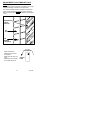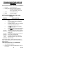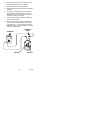
1
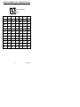
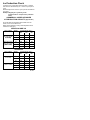
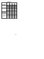
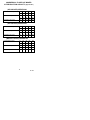
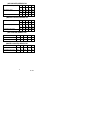
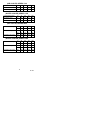
ICE MAKER
POCKET GUIDE
Cornelius Ice Makers Only
Starting with Serial Code FA
June 1990 Production
IMI CORNELIUS
One Cornelius Place
Anoka, MN 55303
1–800–238–3600
TD 184
TD 184
TABLE OF CONTENTS
PAGE
INTRODUCTION . . . . . . . . . . . . . . . . . . . . . . . . . . . . . . .
1
SERIAL NUMBER DATE CODE DEFINITION . . . . . .
2
ORIGINAL OWNER, END-USER
RESPONSIBILITY . . . . . . . . . . . . . . . . . . . . . . . . . . . . . .
3
SEQUENCE OF OPERATION CUBER ONLY . . . . . . .
4
APPROXIMATE PRESSURE RANGES . . . . . . . . . . . .
5
CUBERS . . . . . . . . . . . . . . . . . . . . . . . . . . . . . . . . . . . .
5
FREEZE CYCLE . . . . . . . . . . . . . . . . . . . . . . . . . . .
5
DFROST CYCLE . . . . . . . . . . . . . . . . . . . . . . . . . . .
5
FLAKERS . . . . . . . . . . . . . . . . . . . . . . . . . . . . . . . . . . . .
5
SERIAL NAME PLATE LOCATION. . . . . . . . . . . . . . .
5
PRESSURE SETTINGS. . . . . . . . . . . . . . . . . . . . . . . .
5
ICE PRODUCTION CHECK . . . . . . . . . . . . . . . . . . . . . .
6
COMMERICAL CUBER ICE MAKER
ICE PRODUCTION CAPACITY (Approximate) . . . . .
6
SERIES 300 AND 322 . . . . . . . . . . . . . . . . . . . . . . .
6
SERIES 500 . . . . . . . . . . . . . . . . . . . . . . . . . . . . . . .
6
SERIES 700 . . . . . . . . . . . . . . . . . . . . . . . . . . . . . . .
7
SERIES 900 . . . . . . . . . . . . . . . . . . . . . . . . . . . . . . .
8
SERIES 1400 . . . . . . . . . . . . . . . . . . . . . . . . . . . . . .
9
COMMERICAL FLAKER ICE MAKER
ICE PRODUCTION CAPACITY (Approximate) . . . . .
10
(AIR COOLED) SERIES 200 . . . . . . . . . . . . . . . . .
10
(AIR COOLED) SERIES 525 . . . . . . . . . . . . . . . . .
10
(WATER COOLED) SERIES 525 . . . . . . . . . . . . . .
10
(AIR COOLED) SERIES 725 . . . . . . . . . . . . . . . . .
11
(WATER COOLED) SERIES 725 . . . . . . . . . . . . . .
11
(AIR COOLED) SERIES 750 . . . . . . . . . . . . . . . . .
11
(WATER COOLED) SERIES 750 . . . . . . . . . . . . . .
11
(AIR COOLED) SERIES 1100 . . . . . . . . . . . . . . . .
12
i
TD 184
TABLE OF CONTENTS CONT’D
PAGE
(WATER COOLED) SERIES 1100 . . . . . . . . . . . . .
12
(AIR COOLED) SERIES 2400 . . . . . . . . . . . . . . . .
12
(WATER COOLED) SERIES 2400 . . . . . . . . . . . .
12
THE FOLLOWING MAINTENANCE SHOULD BE PERFORMED AT LEAST EVERY SIX MONTHS ON FLAKED
ICE MACHINES . . . . . . . . . . . . . . . . . . . . . . . . . . . . . . . .
13
FLAKER SANITIZING AND CLEANING
PROCEDURE . . . . . . . . . . . . . . . . . . . . . . . . . . . . . . . . . .
14
CUBER SANITIZING AND CLEANING PROCEDURE
15
ADJUSTMENT FOR ICE BRIDGE THICKNESS . . . . .
17
CHECKOUT PROCEDURE FOR HARVEST BIN
SWITCHES . . . . . . . . . . . . . . . . . . . . . . . . . . . . . . . . . . . .
18
ADJUSTMENT PROCEDURE FOR HARVEST BIN
SWITCHES . . . . . . . . . . . . . . . . . . . . . . . . . . . . . . . . . .
WIRING DIAGRAMS . . . . . . . . . . . . . . . . . . . . . . . . . . . .
18
19
CUBERS . . . . . . . . . . . . . . . . . . . . . . . . . . . . . . . . . . 19-26
FLAKERS . . . . . . . . . . . . . . . . . . . . . . . . . . . . . . . . . . 27-35
TROUBLESHOOTING CUBE ICE MAKERS . . . . . . .
36
STATUS INDICATORS . . . . . . . . . . . . . . . . . . . . . . . . .
36
300 AND 322 SERIES . . . . . . . . . . . . . . . . . . . . . . .
36
500 THRU 1400 SERIES . . . . . . . . . . . . . . . . . . . .
36
TROUBLESHOOTING THE SENSORS . . . . . . . . . . . .
NO ICE BEING FORMED ON
EVAPORATOR. . . . . . . . . . . . . . . . . . . . . . . . . . . . . . . .
36
38
ICE DOES NOT DROP AFTER 4 1/2 MINUTES IN DEFROST CYCLE. . . . . . . . . . . . . . . . . . . . . . . . . . . . . . . 38
ICE FORMS ON BOTTOM HALF OF
EVAPORATOR. . . . . . . . . . . . . . . . . . . . . . . . . . . . . . . .
38
LOW HEAD PRESSURE. . . . . . . . . . . . . . . . . . . . . . .
38
FLUCTUATING LOW SIDE PRESSURE
(MORE THAN 5#). . . . . . . . . . . . . . . . . . . . . . . . . . . . .
39
WATER OVERFLOW RESERVOIR. . . . . . . . . . . . . .
39
ii
TD 184
TABLE OF CONTENTS CONT’D
PAGE
CURTAIN DOES NOT STAY IN PLACE. . . . . . . . . . .
39
ICE TOO THICK OR TOO THIN. . . . . . . . . . . . . . . . .
39
GOES OFF ON CODE 4 . . . . . . . . . . . . . . . . . . . . . . .
39
GOES OFF ON CODE 6. . . . . . . . . . . . . . . . . . . . . . . .
39
HIGH HEAD PRESSURE. . . . . . . . . . . . . . . . . . . . . . .
40
COMPRESSOR WILL NOT START. . . . . . . . . . . . . . .
40
ICE DROPS, BUT UNIT STAYS IN DEFROST OR WILL
NOT SHUT OFF ON FULL BIN. . . . . . . . . . . . . . . . . . 40
COMPRESSOR RUNS WHEN BIN IS FULL OR WHEN
SWITCH IS “OFF” POSITION. . . . . . . . . . . . . . . . . . . 40
FAN MOTOR WILL NOT RUN. . . . . . . . . . . . . . . . . . .
40
WATER PUMP WILL NOT RUN . . . . . . . . . . . . . . . . .
41
GOES OFF ON #2 BIN NOT FULL . . . . . . . . . . . . . . .
41
TROUBLESHOOTING FLAKERS . . . . . . . . . . . . . . . . .
UNIT WILL NOT RUN . . . . . . . . . . . . . . . . . . . . . . . . .
42
42
COMPRESSOR CYCLES
INTERMITTENTLY. . . . . . . . . . . . . . . . . . . . . . . . . . . . .
42
MAKING WET ICE. . . . . . . . . . . . . . . . . . . . . . . . . . . . .
43
UNIT RUNS BUT MAKES NO ICE. . . . . . . . . . . . . . .
43
WATER LEAKS . . . . . . . . . . . . . . . . . . . . . . . . . . . . . . .
43
EXCESSIVE NOISE OR CHATTERING. . . . . . . . . . .
44
MACHINE RUNS WITH FULL BIN OF ICE . . . . . . . .
44
UNIT OFF ON RESET . . . . . . . . . . . . . . . . . . . . . . . . .
45
UNIT GOES OFF ON RESET . . . . . . . . . . . . . . . . . . .
45
iii
TD 184
INTRODUCTION
This guide is published as an aid to the Service Technician. It
is not intended to replace the service manual. In it you will
find useful information not found in the service manual. This
information will help you more quickly identify specific problems, however not all problems or situations may be listed.
We appreciate your comments or suggestions, or if you have
a specific problem not addressed in this guide or service
manual.
Please feel free to contact our service department at:
IMI CORNELIUS
One Cornelius Place
Anoka, MN 55303
1–800–554–3526
The warranty on Cornelius icemakers begins on the date of
installation, as reported on the warranty registration card to
the original owner/user. If no warranty card is received by the
factory, the date of shipment from the factory will determine
the start of the warranty.
Warranty labor will be paid per the labor rate guide and is
subject to change without notice. Call the Service Department for a copy of the current Labor Rate Guide and/or applicable Warranty Document Copy.
This guide covers IMI Cornelius Ice Makers
Manufactured from June 1, 1990 thru
August, 1994.
TD 184
1
SERIAL NUMBER DATE CODE DEFINITION
F A 0000
Sequential Number
Year
Month
MO.
1990
1991
1992
1993
1994
1995
Jan
––
AB
AC
AD
AE
AF
Feb
––
BB
BC
BD
BE
BF
Mar
––
CB
CC
CD
CE
CF
Apr
––
DB
DC
DD
DE
DF
May
––
EB
EC
ED
EE
EF
Jun
FA
FB
FC
FD
FE
FF
Jul
GA
GB
GC
GD
GE
GF
Aug
HA
HB
HC
HD
HE
HF
Sep
JA
JB
JC
JD
JE
JF
Oct
KA
KB
KC
KD
KE
KF
Nov
MA
MB
MC
MD
ME
MF
Dec
NA
NB
NC
ND
NE
NF
2
TD 184
ORIGINAL OWNER, END-USER
RESPONSIBILITY
1.
To verify the equipment installation date by the
return of the warranty registration card to the factory within five days of the installation.
2.
To pay freight or handling charge.
3.
To pay for service labor and/or parts required to
correct improperly installed equipment. Installation
must comply with the installation instructions.
4.
To pay for normal maintenance, adjustments and
cleaning.
5.
To pay for service labor and/or parts required to
correct unit modification or the use of non-approved remote condensers.
6.
To pay for service labor and/or parts required because of neglect, abuse, misuse, accident, fire,
flood, freezing or any act of God.
7.
To pay for mileage, truck charges, travel time, premium labor for holidays, weekends or after hours
work, flat rate service call charges, miscellaneous
tool charges, use of diagnostic meters or equipment and all material not listed on the Warranty
Time Rate Guide.
3
TD 184
SEQUENCE OF OPERATION
CUBER ONLY
After the installation of the water lines from the primary water
supply, the float valve will be open and remain open until the
reservoir is filled to the proper level. (1/4” below the support).
Note: Primary water supply must not be less than 20 psi, nor
mor then 50 psi on Float Valves with no Flow Washer, or 125
psi for Float Valves with Flow Washer.
When the on–off clean switch is in the ”clean” position the
water pump will run. All other components are off. When the
switch is in the ”on“ position the compressor will be energized, after a short delay the fan will come on. When the
temperature of the evaporator reaches 20°F the sensor in
the evaporator tells the control board to turn the pump on.
When the evaporator sensor, senses an approximate temperature of 0°F it tells the control board to switch to the harvest mode.
In the harvest cycle the pump will remain engaged for
approximately 12 seconds. The compressor, hot gas valve
and dump solenoid will be engaged. When the ice is harvested, the curtain opens, breaking the magnetic field to the
proximity switch and the unit will return to the ”Freeze“ cycle.
If the curtain remains open, after approximately 8 seconds
the unit will shut down, indicating the bin is full. Note: On
units that are stacked, an interface cable connects the two
control boards. When the bottom unit shuts off due to a full
bin, the top will continue to operate until it completes the
cycle it is in and then will shut off on full bin (#2).
To check the control board: When the unit is in the freeze
cycle, power should be to the compressor, fan motor and
water pump (after evaporator reaches 20°). There should be
no power to the hot gas valve or the dump solenoid. When
the unit is in the defrost cycle, there should be power to the
compressor, hot gas solenoid, and dump solenoid. (The
pump will have power for approximately 12 seconds into the
defrost cycle).
4
TD 184
Approximate Pressure Ranges
Depending on operating ambient and incoming
water temperature.
CUBERS
Freeze
Cycle
DFROST
CYCLE
Refrigerant
Head
Pressure
Suction
Pressure
Start – End
Head
Pressure
Suction
Pressure
R-12
125
20-12
85-95
45
R-22
225
35-22
180-190
50
R-502
225-250
30-18
180-190
50
FLAKERS
Refrigerant
Head Pressure
Suction Pressure
R-12
125
6-9
R-22
225
22-24
R-502
225
18-20
For Volts, Amps, Fuse Size and Refrigerant Charge see
Serial Nameplate.
Serial Name Plate Location.
1.
Electric box inside machine.
2.
Lower left side, Corner of cabinet.
Pressure Settings.
Crankcase pressure regulating valve factory setting with unit
in the Harvest Cycle:
R-22
45 lbs. maximum
R-502 50 lbs. maximum
Water cooled factory high side pressure settings with units in
the ice making mode.
R-12
120 lbs.
R-502 240 to 250 lbs.
R-22
200 lbs. for 300 and 322 Series
225 lbs. for 500 and 1400 Series
5
TD 184
Ice Production Check
Cycle time (CT) = freeze time plus harvest time, in minutes
and seconds. 1440 divided by CT = number of cycles per 24
hours.
Measure weight of ice from one cycle in pounds and fractions
of a pound.
Example: Weight/cycle x cycles/day = total
production/24 hrs. Compare to the production
tables.
COMMERCIAL CUBER ICE MAKER
ICE PRODUCTION CAPACITY (Approximate)
Air Cooled: Take air temperature at the intake of the condenser, 2” from the condenser fins.
Water Cooled: Measure Incoming water temperature at the
outlet of the “float” valve.
SERIES 300 AND 322
MODEL NUMBER
(CONDENSER)
AMBIENT
TEMP. ° F
AC-300-SS-MH
AC-322-SS-MH
Air Cooled)
WC-300-SS-MH
WC-322-SS-MH
(Water cooled)
INCOMING WATER TEMP. ° F
50°
70°
80°
70°
243
227
216
80°
224
209
198
90°
199
176
160
70°
225
206
193
80°
212
191
179
90°
198
176
164
SERIES 500
MODEL NUMBER
(CONDENSER)
AMBIENT
TEMP. ° F
AC-500
Air Cooled)
WC-500
(Water cooled)
INCOMING WATER TEMP. ° F
50°
70°
80°
70°
460
400
380
80°
430
390
360
90°
400
370
330
70°
500
450
400
80°
495
445
395
90°
490
440
390
6
TD 184
SERIES 700
(CONDENSER)
(Air Cooled)
(Water Cooled)
INCOMING WATER TEMP. ° F
AMBIENT
TEMP. ° F
50°
70°
80°
70°
610
550
520
80°
575
510
480
90°
530
470
445
70°
655
595
550
80°
645
590
545
90°
635
585
540
OUTSIDE
AIR ° F
(Remote-Air)
50°
625
555
530
NOTE: Remote
Unit designed for
use with CS.120
Remote Condenser.
70°
615
545
520
90°
570
505
480
110°
500
450
425
7
TD 184
SERIES 900
MODEL NUMBER
(CONDENSER)
AMBIENT
TEMP. ° F
AC-900-SS-MH
(Air Cooled)
WC-900-SS-MH
(Water Cooled)
INCOMING WATER TEMP. ° F
50°
70°
80°
70°
696
620
594
80°
650
582
556
90°
580
511
494
70°
674
610
552
80°
665
610
545
90°
666
601
529
50°
741
650
620
70°
720
645
599
90°
602
528
502
110°
509
449
429
OUTSIDE
AIR ° F
RC-900-SS-MH
(Remote-Air)
Note: Remote
unit designed for
use with CS–120
remote condenser
8
TD 184
SERIES 1400
MODEL NUMBER
(CONDENSER)
AMBIENT
TEMP. ° F
(Air Cooled)
(Water Cooled)
INCOMING WATER TEMP. ° F
50°
70°
80°
70°
1400
1240
1180
80°
1320
1175
1110
90°
1210
1085
1025
70°
1420
1250
1120
80°
1390
1220
1095
90°
1360
1190
1070
50°
1300
1190
1145
70°
1230
1180
1130
90°
1100
1050
990
110°
950
900
860
OUTSIDE
AIR ° F
(Remote-Air)
9
TD 184
COMMERICAL FLAKER ICE MAKER
ICE PRODUCTION CAPACITY (Approximate)
(AIR COOLED) SERIES 200
°F
70
80
90
100
°C
21
27
32
38
Inlet Water Temp.
°F
50
60
70
80
°C
10
16
21
27
Production per 24 hrs.
Lbs
200
175
150
100
Ambient Room Temp.
(AIR COOLED) SERIES 525
Ambient Room Temp.
Inlet Water Temp.
Production per 24 hd.
°F
70
80
90
100
°C
21
27
32
38
°F
50
60
70
80
°C
10
16
21
27
Lbs
600
540
465
408
(WATER COOLED) SERIES 525
Ambient Room Temp.
Inlet Water Temp.
Production per 24 hrs.
°F
70
80
90
100
°C
21
27
32
38
°F
50
60
70
80
°C
10
16
21
27
Lbs
588
549
471
444
10
TD 184
(AIR COOLED) SERIES 725
Ambient Room Temp.
°F
70
80
90
100
°C
21
27
32
38
Inlet Water Temp.
°F
50
60
70
80
°C
10
16
21
27
Production per 24 hrs.
Lbs
690
590
490
390
(WATER COOLED) SERIES 725
Ambient Room Temp.
Inlet Water Temp.
Production per 24 hrs.
°F
70
80
90
100
°C
21
27
32
38
°F
50
60
70
80
°C
10
16
21
27
Lbs
765
675
618
480
(AIR COOLED) SERIES 750
Ambient Room Temp.
°F
70
80
90
100
Inlet Water Temp.
°F
50
60
70
80
Production per 24 hrs.
Lbs
690
590
490
390
90
100
(WATER COOLED) SERIES 750
Ambient Room Temp.
°F
70
80
Inlet Water Temp.
°F
50
60
70
80
Production per 24 hrs.
Lbs
756
675
610
480
11
TD 184
(AIR COOLED) SERIES 1100
Ambient Room Temp.
°F
70
80
90
100
Inlet Water Temp.
°F
50
60
70
80
Production per 24 hrs.
Lbs
1050
960
840
700
(WATER COOLED) SERIES 1100
Ambient Room Temp.
°F
70
80
90
100
Inlet Water Temp.
°F
50
60
70
80
Production per 24 hrs.
Lbs
1050
960
880
780
(AIR COOLED) SERIES 2400
Ambient Room Temp.
Inlet Water Temp.
Production per 24 hrs.
°F
70
80
90
100
°C
21
27
32
38
°F
50
60
70
80
°C
10
16
21
27
Lbs
2400 2110 1800 1540
(WATER COOLED) SERIES 2400
°F
70
80
90
100
°C
21
27
32
38
Inlet Water Temp.
°F
50
60
70
80
10
16
21
27
Production per 24 hrs.
Lbs
Ambient Room Temp.
°C
12
2365 2100 1840 1600
TD 184
THE FOLLOWING MAINTENANCE SHOULD
BE PERFORMED AT LEAST EVERY SIX
MONTHS ON FLAKED ICE MACHINES
1.
Check power supply with machine running for proper voltage.
2.
Check water level in the float tank reservoir. Water
level should be maintained at the top of the evaporator. Adjust if necessary.
3.
Clean the air-cooled condenser coil with a stiff
brush or vacuum cleaner.
CAUTION: CONDENSER COOLING FINS ARE
SHARP, USE CARE WHEN CLEANING.
4.
Clean the ice storage bin and flush the bin drain at
least once a month.
5.
If a water conditioner is installed in the inlet water
line, change, replace or clean the filter, strainer or
cartridge as required.
6.
If heavy mineral deposits on the auger and evaporator shell are encountered due to bad local water
conditions, follow sanitizing and cleaning procedure.
7.
Loosen hold–down cam locks and remove gear
motor assembly.
8.
Check thrust washer; replace if noticeably worn.
9.
Lift out auger and examine for wear. If the Helix
auger or the corkscrew auger round bar becomes
flat on the inside more than 1/8 of an inch over a
length of two inches or more it should be replaced.
NOTE: HELIX AUGERS DO HAVE MACHINED
FLAT RELIEF SURFACES. DON’T CONFUSE
THEM WITH WORN FLAT AREAS.
Check the insert in the bottom ring of the Helix auger and replace if excessively worn.
10. Check shell vertical strips for wear. Replace the
shell if excessive wear shown.
11. Check O-ring, replace if worn or cut.
13
TD 184
12. Re–assemble. steps 6 through 10.
CAUTION: IN RE–ASSEMBLING THE AUGER
GEARMOTOR, THE HOLD DOWN CLAMPS
MUST BE TIGHT AND SECURE. IN RE–INSTALLING THE EVAPORATOR SHELL, BE ABSOLUTELY SURE THAT THE “O” RING IS NOT
PINCHED OFF AS THIS WOULD CAUSE A WATER LEAK AROUND THE BASE OF THE EVAPORATOR. LUBRICATE THE “O” RING WITH
FOOD GRADE LUBRICANT BEFORE RE–ASSEMBLING SHELL.
13. Check for alignment of ice chute. Make sure chute
gasket is not blocking path of ice flow.
14. Check bin thermostat operation. In the mid–range
position the bin thermostat will open at 42° F and
has 6° F differential.
FLAKER SANITIZING AND CLEANING PROCEDURE
1.
Turn switch to “OFF” to stop unit.
2.
(a) Turn water off and remove water hose float
chamber and proceed to drain the float chamber
and evaporator; or
(b) Remove float chamber cover and while holding
float up to prevent more water from entering the
float chamber, remove water hose from float chamber and proceed to drain the float chamber and
evaporator.
3.
With the float still held closed or water still off, restore water hose to float chamber and add 1/4 oz.
of “sanitizer” (see not below) to the float chamber.
Release float arm so that chamber fills with water.
Turn water on, if necessary.
4.
Turn switch to “ON” position and make ice for a
minimum of 10 minutes.
5.
Remove all ice from bin.
6.
During the period in which the ice is being made,
mix up the “sanitizer” for the bin and use as follows:
14
TD 184
Add 1/2 oz. “sanitizer” to a gallon of lukewarm water. With a non–metallic bristle brush, scrub the interior of the ice bin including the under side of the
door, and the outside of the ice chute that protrudes
into the ice bin.
7.
Rinse interior bin with clean water. (NOTE: Steps 6
and 7 should take no less than 10 minutes).
8.
Not less than 10 minutes after completing step #4,
turn switch to “OFF” and repeat step #2. After the
evaporator and float chamber have drained, restore
hose to float chamber, release float, replace float
cover and turn water on if necessary.
9.
Turn switch to “ON”. Collect and throw away the
first gallon of ice.
NOTE: APPROVED SANITIZER: “Calgon Ice
Machine Sanitizer” or Household Bleach.
CUBER SANITIZING AND CLEANING PROCEDURE
1.
Remove front panel to gain access to the on–off–
clean switch.
2.
Push switch to “clean” and allow the ice on the
evaporator to release of melt away.
3.
Remove ice from storage bin.
4.
If lime scale is present add 2 oz. of “Lime-A-Way” or
“Calgon Nickelsafe Ice Machine Cleaner” directly
into water reservoir. Circulate for no longer than 15
minutes. Depress dump valve switch on control
box and allow cleaner or sanitizer to drain away.
Allow float valve to fill reservoir with clean, fresh
water. Circulate for approximately 1 minute. Depress dump valve switch and allow water to drain
away. Repeat three times.
CAUTION: All ice machine cleaner must be flushed out of
the system before the sanitizing solution is used in Step 5.
The reaction of the two chemicals can cause hazardous gases
to be generated.
5.
Pour 1/2 oz. of household bleach into the water reservoir and circulate for 15 minutes to sanitize the
15
TD 184
circulating water system including the evaporator,
pump, distributor and all inter-connecting vinyl tubing. Depress dump valve switch on control box and
allow cleaner or sanitizer to drain away. Allow float
valve to fill reservoir with clean, fresh water. Circulate for approximately 1 minute. Depress dump
valve switch and allow water to drain away. Repeat
three times.
6.
Mix a sanitizing solution of 1oz. household bleach
to one gallon of water. Using a non-metallic bristle
brush, scrub the following:
A.
Inside surface of the ice bin including top and
door.
B.
Inside surface of the ice maker to include evaporator section in the ice machine including the
top, front panel and evaporator splash curtain.
C.
Make sure splash curtain is correctly positioned.
7.
Depress dump valve switch on control box and allow cleaner or sanitizer to drain away. Allow float
valve to fill reservoir with clean, fresh water. Circulate for approximately 1 minute. Depress dump
valve switch and allow water to drain away. Repeat
three times.
8.
Push switch from “clean” to “on” position.
9.
Replace front panel.
16
TD 184
ADJUSTMENT FOR ICE BRIDGE THICKNESS
An ice bridge connecting all cubes is necessary for a proper
harvest of discharge of cubes from the evaporator.
To increase ice bridge thickness carefully turn adjustment
screw counter-clockwise no more than one turn at a time.
Wait and check thickness before re-adjusting. (See Diagram
1 & 2)
EVAPORATOR
CROSS
SECTION
ICE
SLAB
ICE
BRIDGE
THICKNESS
Series 300 and 322:
Adjusting screw located
on left center.
Series 500, 700, 900, and
1400:
Adjusting screw is located
on the upper left corner.
17
INCREASE
ADJUST
HERE
TD 184
CHECKOUT PROCEDURE FOR HARVEST
BIN SWITCHES
Turn on the ice machine and move the evaporator curtains(s)
away from the evaporator(s). The ice machine should then
shut off in approximately 8 seconds. (see detail A).
Slowly let the evaporator curtain(s) move back toward the
evaporator(s) until the bottom edge of the curtains(s) is at
least at the bent edge of the water reservoir or closer to the
evaporator. With the curtains(s) at that position the machine
should start.
ADJUSTMENT PROCEDURE FOR HARVEST
BIN SWITCHES
If adjustment is necessary, loosen acorn nuts and move
proximity switch closer to the curtain(s) and make sure the
curtain is properly mounted. (See detail A).
ACORN
NUT
CURTAIN
EDGE
SENSOR
THERMOWELL
MAGNET
PROXIMITY
SWITCH
EVAPORATOR
CURTAIN
ACORN
NUT
WATER
RESERVOIR
18
TD 184
TROUBLESHOOTING CUBE ICE
MAKERS
STATUS INDICATORS 300 AND 322 SERIES
1.
No Lights
Unit in freeze cycle.
2.
Flashing Red Bridge thickness temperature
has been reached. Harvest to
start in approximately 30 seconds
3.
yellow
Unit in Harvest Cycle
4.
Green
Unit off on Full Bin
STATUS INDICATORS 500 THRU 1400
SERIES
STATUS
EXPLANATION
0
Unit is in freeze cycle, making ice, no problems.
1
Unit is in harvest cycle, ice should drop
shortly, no problems.
2
Indicates a full bin condition, unit off, water
curtain being held open with ice.
4
Unit OFF due to suction line not pulling
down to at least 40°F.
6
Unit is OFF due to condenser temperature
climbing too high. Manual reset required.
Decimal
Point OFF
Indicates that all sensors, except condenser, are switched off for first six minutes of
freeze cycle.
Decimal
Point ON
Indicates that evaporator and suction line
sensors have switched “ON”.
Decimal
Point
FLASHING
Indicates evaporator temperature has
pulled down and unit will go into harvest
after time delay.
FOR MANUAL RESET - PUSH MASTER SWITCH TO
“OFF” - WAIT 10 SECONDS - PUSH TO “ON” OR PUSH
RESET BUTTON
TROUBLESHOOTING THE SENSORS
1.
Turn off power to machine.
2.
Remove the front panel and electrical box cover of
the machine.
19
TD 184
3.
Cut the suspected sensor wire at least six inches
from the thermowell in which it is located.
4.
Remove the sensor from the thermowell.
5.
Carefully separate the wires and strip the insulation
off the end.
6.
Pack a glass or container with ice and add some
water to make an ice water solution. Check the
temperature of the ice water with an accurate thermometer. Ice water must be 32°F.
7.
Insert the sensor into the ice water and soak for a
minimum of two minutes.
8.
With a zerod ohmmeter, measure the resistance
across the two wires of the sensor lead. It should
read 2815 ohms 10% (281 ohms)on units built
before March 1994; 5% (140 ohms) on units built
from March 1994 and later.
OHMMETER
LEADS
OHMMETER
2815
SENSOR
20
BATH 32_F
TD 184
NO ICE BEING FORMED ON EVAPORATOR.
1.
No water in reservoir – clean or replace float.
2.
Pump not running – check sensor & board.
3.
Dump solenoid – open during freeze cycle.
4.
Refrigeration problems – check for leaks.
1.
Dirty Condenser.
2.
Hot Gas valve open.
3.
Weak compressor.
ICE DOES NOT DROP AFTER 4 1/2 MINUTES IN DEFROST CYCLE.
1.
Is Hot Gas valve opening?
2.
Is the evaporator free of scale & deposits or loosing
its plating?
3.
Are the dividers bent, warped, or separated from
evaporator back.?
4.
Is CPR valve set at 50 PSI in defrost?
5.
Head pressure dropping too low?
6.
Is bridge thickness 1/8” minimum?
ICE FORMS ON BOTTOM HALF OF EVAPORATOR.
1.
Is reservoir overflowing?
2.
Is dump solenoid open?
3.
Is unit low on refrigerant?
4.
Is Hot Gas valve open during freeze cycle?
5.
TXV feeding properly?
LOW HEAD PRESSURE.
1.
Is there the proper charge in unit?
2.
Is there a leak in the system?
3.
Are ambient conditions to cold? (below
50° F).
4.
On water cooled units is the water valve set properly?
5.
Is incoming water to condenser, too cold (below
45°F).
21
TD 184
FLUCTUATING LOW SIDE PRESSURE
(MORE THAN 5#).
1.
Is TXV bulb tight on top of suction line?
2.
Is there a proper charge in unit?
3.
Is water running over the evaporator continuously?
4.
TXV is faulty.
WATER OVERFLOW RESERVOIR.
1.
Check water pressure, not less than 20 psi, and
not more than 50 psi on Float Valves with no Flow
Washer, or 125 psi for Float Valves with Flow
Washers..
2.
Float defective or set too high.
3.
Obstruction in water line to pump.
4.
Obstruction in cross–over tube.
CURTAIN DOES NOT STAY IN PLACE.
1.
Adjust rear bracket closer to evaporator.
ICE TOO THICK OR TOO THIN.
1.
Adjust potentiometer (Bridge adjustment CCW
thickner, CW thinner).
2.
Check evaporator sensor for proper ohms.
3.
Is dump solenoid open or float overfilling reservoir?
GOES OFF ON CODE 4
1.
Refrigerant Leak.
2.
High suction pressure.
3.
Check sensor for proper ohms.
GOES OFF ON CODE 6.
1.
Is fan operating during freeze cycle & fan blade
free.
2.
Is condenser clean?
3.
Is sensor defective?
4.
On “water cooled” is there water to the condenser?
22
TD 184
HIGH HEAD PRESSURE.
1.
Is condenser clean.
2.
Is fan operating properly?
3.
On “water cooled” is water valve adjusted properly?
4.
Too high ambient conditions (above 100° F).
COMPRESSOR WILL NOT START.
1.
Is there power from the board?
2.
Is there power from the power relay?
3.
Are start components good?
4.
Check LRA.
ICE DROPS, BUT UNIT STAYS IN DEFROST
OR WILL NOT SHUT OFF ON FULL BIN.
1.
Is proximity switch too close to magnet or faulty
switch?
2.
Is proximity switch plugged into board properly?
3.
Board is bad?
COMPRESSOR RUNS WHEN BIN IS FULL
OR WHEN SWITCH IS “OFF” POSITION.
1.
Bad power relay (contacts stuck closed).
FAN MOTOR WILL NOT RUN.
1.
Is there low head pressure?
2.
Is fan motor locked up?
3.
Is condenser sensor good?
4.
Are connections tight on board?
5.
Is control board bad?
23
TD 184
WATER PUMP WILL NOT RUN
1.
Is evaporator below 20°F?
2.
Is evaporator sensor good?
3.
Is pump motor good – Does it run in the “clean”
position?
4.
Are connections tight on board?
5.
Is control board bad?
GOES OFF ON #2 BIN NOT FULL
1.
Curtain out of adjustment?
2.
Bridge too thin – Cubes breaking off too soon?
3.
Bad proximity switch?
4.
Bad control board?
24
TD 184
TROUBLESHOOTING FLAKERS
Trouble
1. Unit will not run
2. Compressor
cycles
intermittently.
Probable Cause
Remedy
On-off switch in
“off” position.
Turn switch to “on”
Defective on-off
switch.
Check and replace.
Blown fuse.
Replace fuse and
check for cause of
blown fuse.
Thermostat set
too warm for
ambient.
Adjust colder.
Power relay
contacts
corroded.
Check and clean.
Defective
thermostat.
Check and replace
Loose electrical
connection
Check wiring
Low voltage.
Check line voltage
Dirty
condenser.
Clean condenser.
Air circulation
restricted.
Remove restriction.
Defective
condenser fan
motor.
Check and replace.
Defective relay,
overload
protector or
starting
capacitor.
Check and replace.
25
TD 184
Trouble
Probable Cause
Remedy
2. Compressor
cycles
intermittently.
(cont’d)
Loose electrical
connection.
Check wiring.
3. Making wet ice.
Surrounding air
temperature too
high.
Correct or move
unit.
High water level
in float
reservoir.
Lower water level,
Dirty condenser
Clean condenser.
Faulty
compressor
Check and replace
Refrigerant leak
Check and repair
“O” ring leaking
at bottom of
evaporator shell
Check and replace
Leak in
refrigerant
system
Check and repair
Moisture in
system
Check, dehydrate
and add drier to
system
No water
Check water supply
“O” ring leaking
at bottom of
evaporator shell
Check and replace
“O” ring
Compressor
not running
Check electrical
Worn or bad
float valve
Check and replace
Float and arm
assembly stuck
Check and replace
4. Unit runs but
makes no ice.
5. Water leaks
26
TD 184
Trouble
Probable Cause
5. Water leaks
(cont’d)
“O” ring leaking
at bottom of
evaporator shell
Check and replace
Storage bin
drain and tubing
Check and repair
Mineral or scale
deposits on
inside of
evaporator shell
Remove and clean
inside surfaces by
immersing
evaporator shell in
ice machine
cleaner.
Intermittent
water supply
Check inlet water
line
Water level in
float tank too
low
Check and adjust
water level
Auger
gearmotor
end-play or
worn bearings
Repair or replace
Air lock in
gravity water
supply line from
float tank to
evaporator shell
Remove Air Lock.
Storage bin
thermostat set
too cold
Check and adjust
warmer
Bin thermostat
thermowell out
of path of ice
Adjust thermowell
6. Excessive noise
or chattering.
7. Machine runs
with full bin of ice
27
Remedy
TD 184
Trouble
8. Unit off on reset
9. Unit goes off on
reset
Probable Cause
Remedy
Ice jams up in
evaporator shell
Clean inside
surface of
evaporator shell
Bin thermostat
will not shut off
machine. Set
too cold
Check and adjust or
replace
Auger motor
has worn
bearings
Check and replace
Ice chute out of
alignment,
restricted ice
flow out of
evaporator
section
Re-align
Ice chute
center
separator bent
restricting ice
flow out of
evaporator
section
Replace ice chute
Incoming water
temperature too
cold
Maintain
temperature above
50° F
Bin thermostat
does not shut
off when bin is
full if ice
Replace bin
thermostat if
necessary
Mineral or scale
deposits on
inside of
evaporator shell
and evaporator
Inspect and clean
28
TD 184
Trouble
9. Unit goes off on
reset (cont’d)
Probable Cause
Remedy
Strips loose or
missing on
inside of
evaporator shell
Inspect and replace
evaporator shell if
necessary
Low ambient
temperature in
room where
unit is located
Maintain
temperature above
50 degrees
Gearmotor
sticking which
causes it to
draw excessive
amperage
Check amp draw of
gearmotor with an
amprobe
Plugged
capillary tube or
expansion
valve, causing
low back
pressure
Check back
pressure, replace
cap tube or valve,
evacuate and
re-charge system,
replace
drier-strainer
Slight leak,
causing low
back pressure
Check back
pressure, find gas
leak, repair leak,
evacuate system,
add drier and
recharge
Loose
hold-down assy
Check and tighten
or replace
Auger worn
excessively on
the inside
surfaces
causing thicker
flaked ice to be
made
Replace auger
29
TD 184
Trouble
9. Unit goes off on
reset (cont’d)
Probable Cause
Remedy
Auger out of
line causing
excessive wear
on the lower
outside surface
where it rubs
against
evaporator shell
liner at the
bottom
Replace auger and
evaporator shell
Broken auger
Replace auger
Evaporator
surfaces worn
or gouged,
causing thicker
ice to be made
Inspect and replace
evaporator if
necessary
Auger guide
bushing worn
down
Replace auger
guide bushing
(corkscrew type
augers only)
Loose
gearmotor
mounting plate
Check and tighten
Low water level
in float tank
reservoir
Adjust float arm to
maintain correct
water level
Worn thrust
washer
Replace
30
TD 184