1
Maestro User Manual
Maestro 8.0
User Manual
Schrödinger Press
Copyright © 2007 Schrödinger, LLC. All rights reserved. CombiGlide, Epik, Glide,
Impact, Jaguar, Liaison, LigPrep, Maestro, Phase, Prime, PrimeX, QikProp, QikFit,
QikSim, QSite, SiteMap, and Strike are trademarks of Schrödinger, LLC.
Schrödinger and MacroModel are registered trademarks of Schrödinger, LLC.
MCPRO is a trademark of William L. Jorgensen.
To the maximum extent permitted by applicable law, this publication is provided “as
is” without warranty of any kind. This publication may contain trademarks of other
companies.
Please note that any third party programs (“Third Party Programs”) or third party
Web sites (“Linked Sites”) referred to in this document may be subject to third
party license agreements and fees. Schrödinger, LLC and its affiliates have no
responsibility or liability, directly or indirectly, for the Third Party Programs or for
the Linked Sites or for any damage or loss alleged to be caused by or in connection
with use of or reliance thereon. Any warranties that we make regarding our own
products and services do not apply to the Third Party Programs or Linked Sites, or
to the interaction between, or interoperability of, our products and services and the
Third Party Programs. Referrals and links to Third Party Programs and Linked Sites
do not constitute an endorsement of such Third Party Programs or Linked Sites.
The Schrödinger software distribution includes third-party products. For details of
third-party software copyrights, terms, and conditions, see the Legal Notices for
Third-Party Software, at $SCHRODINGER/docs/html/third_party_legal.html.
Revision B, October 2007
Contents
Document Conventions .................................................................................................... xv
Chapter 1: Maestro Overview ........................................................................................ 1
1.1 General Interface Design ......................................................................................... 1
1.1.1 Maestro Windows ............................................................................................... 1
1.1.2 Mouse Functions................................................................................................. 2
1.1.3 Keyboard Shortcuts ............................................................................................ 3
1.2 Maestro Workflow ..................................................................................................... 3
1.3 Maestro Projects ........................................................................................................ 3
1.4 Job Launching and Incorporation .......................................................................... 5
1.5 Citing Maestro in Publications ................................................................................ 7
Chapter 2: The Maestro Main Window .................................................................... 9
2.1 Starting Maestro ........................................................................................................ 9
2.1.1 Starting Maestro on a Windows Host................................................................ 10
2.1.2 Starting Maestro on a UNIX Host ..................................................................... 10
2.2 The Main Window .................................................................................................... 11
2.3 The Menu Bar ........................................................................................................... 13
2.4 The Toolbar .............................................................................................................. 14
2.5 The Status Bar ......................................................................................................... 17
2.6 The Sequence Viewer ............................................................................................. 17
2.7 Shortcut Menus ....................................................................................................... 19
2.8 Mouse Functions ..................................................................................................... 22
2.9 Shortcut Keys .......................................................................................................... 23
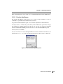
2.10 Finding Objects in the Workspace ..................................................................... 24
2.10.1 Specifying the Search Object.......................................................................... 24
2.10.2 Presentation of the Found Objects.................................................................. 25
2.10.3 Performing the Search .................................................................................... 26
Maestro 8.0 User Manual
iii
Contents
2.11 Undoing Workspace Operations ........................................................................ 27
2.11.1 Undoing Operations on the Structures............................................................ 27
2.11.2 Undoing Operations on the View .................................................................... 27
2.12 Ending a Maestro Session ................................................................................... 28
Chapter 3: Importing and Exporting Structures and Data ....................... 29
3.1 Importing Structures .............................................................................................. 29
3.1.1 Selecting Files................................................................................................... 30
3.1.2 Selecting Import Settings.................................................................................. 33
3.1.3 Error Reporting for PDB Files ........................................................................... 34
3.1.4 Entry Names for Imported Structures ............................................................... 35
3.1.5 Reading Jaguar Input Files ............................................................................... 35
3.2 Exporting Structures .............................................................................................. 36
3.2.1 Selecting Export Settings.................................................................................. 37
3.2.2 Exporting Multiple Files..................................................................................... 38
3.3 Exporting Data to a Spreadsheet ......................................................................... 40
3.4 Importing Data From a Spreadsheet .................................................................... 41
Chapter 4: Building and Adjusting Structures ................................................... 45
4.1 The Build Panel ........................................................................................................ 45
4.2 Building a Structure From Fragments ................................................................. 47
4.2.1 Building Structures Using Place Mode.............................................................. 49
4.2.2 Building Structures Using Grow Mode .............................................................. 50
4.3 Building a Structure From Atoms ........................................................................ 51
4.4 Changing Elements ................................................................................................. 53
4.5 Changing the Bond Order and Formal Charge .................................................. 54
4.6 Fusing or Connecting Structures ......................................................................... 55
4.7 Adjusting the Geometry ......................................................................................... 57
4.7.1 Adjusting Distances, Angles, and Dihedral Angles ........................................... 57
4.7.2 Adjusting Peptide Linkages and Side Chains ................................................... 59
iv
Maestro 8.0 User Manual
Contents
4.7.3 Adjusting the Stereochemistry .......................................................................... 61
4.7.4 Cleaning up the Geometry ................................................................................ 61
4.8 Applying a Hydrogen Treatment ........................................................................... 62
4.9 Changing Atom Properties .................................................................................... 64
4.10 Changing Residue Properties ............................................................................. 68
4.11 Defining Dummy Atoms ....................................................................................... 69
4.12 Deleting Atoms ...................................................................................................... 70
Chapter 5: Selecting Atoms .......................................................................................... 71
5.1 Toolbar Buttons ....................................................................................................... 71
5.2 Picking Tools ............................................................................................................ 71
5.3 The Atom Selection Dialog Box ............................................................................ 73
5.3.1 Selecting Atoms by Property............................................................................. 75
5.3.2 Selecting Atoms by Connectivity....................................................................... 75
5.3.3 Selecting Atoms Using Previously Defined Sets or Selections ......................... 76
5.3.4 Combining and Modifying Atom Selections ...................................................... 76
5.3.5 Selecting Atoms by Proximity............................................................................ 77
5.3.6 Editing and Storing Expressions ....................................................................... 77
5.3.7 Examples of Atom Selection ............................................................................. 78
Chapter 6: Displaying Structures ............................................................................... 81
6.1 Changing Atom Color ............................................................................................. 81
6.1.1 Applying a Single Color..................................................................................... 81
6.1.2 Using Predefined Schemes to Color Atoms...................................................... 83
6.2 Changing Molecular Representations ................................................................. 84
6.2.1 Changing the Representation of Atoms ............................................................ 85
6.2.2 Changing the Representation of Bonds ............................................................ 85
6.2.3 Changing Representation Attributes ................................................................. 87
6.2.4 Rendering Proteins as Ribbons ........................................................................ 88
6.3 Labeling Atoms ........................................................................................................ 90
Maestro 8.0 User Manual
v
Contents
6.4 Displaying and Undisplaying Atoms ................................................................... 92
6.4.1 Selectively Displaying Atoms ............................................................................ 93
6.4.2 Displaying Crystallographically Related Atoms and Positions .......................... 94
Chapter 7: Manipulating Structures ......................................................................... 95
7.1 Global Transformations.......................................................................................... 95
7.2 Local Transformations............................................................................................ 96
7.2.1 Selecting Atoms for Transformation .................................................................. 98
7.2.2 Selecting a Rotation Center .............................................................................. 98
7.3 Tiling Multiple Entries............................................................................................. 98
Chapter 8: Projects.............................................................................................................. 99
8.1 Project Operations .................................................................................................. 99
8.1.1 Creating and Opening Projects......................................................................... 99
8.1.2 Saving and Closing Projects ........................................................................... 100
8.1.3 Deleting Projects............................................................................................. 101
8.1.4 The Project Selector Panels............................................................................ 101
8.1.5 The Project Summary Panel ........................................................................... 102
8.2 Adding Entries to a Project ................................................................................. 103
8.2.1 Importing Structures From a File .................................................................... 104
8.2.2 Creating Entries From Workspace Structures................................................. 104
8.2.3 Incorporating Entries From Job Output........................................................... 104
8.2.4 Merging Entries From Another Project............................................................ 105
8.3 The Project Table Panel ........................................................................................ 105
8.3.1 The Project Table Toolbar ............................................................................... 106
8.3.2 The Project Table Menus ................................................................................ 107
8.3.3 Mouse Functions in the Project Table ............................................................. 108
8.3.4 Project Table Shortcut Menus ......................................................................... 109
8.3.5 Use of the Keyboard in the Project Table ........................................................ 112
8.3.6 Configuring the Project Table.......................................................................... 113
8.3.7 Navigating the Project Table ........................................................................... 114
8.3.8 Finding Text in the Project Table ..................................................................... 114
vi
Maestro 8.0 User Manual
Contents
8.4 Selecting Project Entries ..................................................................................... 115
8.4.1 The Select Menu............................................................................................. 116
8.4.2 Selecting Entries By Property ......................................................................... 116
8.4.3 Selecting Entries Using the Plot Panel ........................................................... 118
8.4.4 Selection Examples ........................................................................................ 118
8.5 Operating on Entries............................................................................................. 119
8.5.1 Including, Excluding, and Fixing Entries ......................................................... 119
8.5.2 Renaming Entries ........................................................................................... 119
8.5.3 Duplicating Entries .......................................................................................... 120
8.5.4 Merging Multiple Entries ................................................................................. 120
8.5.5 Splitting Entries by Molecule........................................................................... 120
8.5.6 Grouping Entries ............................................................................................. 120
8.5.7 Deleting Entries............................................................................................... 122
8.5.8 Moving Entries ................................................................................................ 122
8.5.9 Sorting Entries and Entry Groups ................................................................... 123
8.6 The ePlayer ............................................................................................................. 126
8.6.1 ePlayer Modes ................................................................................................ 126
8.6.2 ePlayer Options............................................................................................... 127
8.7 Viewing Poses ........................................................................................................ 128
8.8 Entry Properties..................................................................................................... 129
8.8.1 Creating New Properties................................................................................. 129
8.8.1.1 Adding Properties with a Default Value ................................................. 129
8.8.1.2 Adding Properties by Copying .............................................................. 130
8.8.1.3 Calculating Properties from Structural Data........................................... 130
8.8.1.4 Calculating Properties from Other Properties ........................................ 131
8.8.2 Editing Properties ........................................................................................... 133
8.8.3 Copying Properties ......................................................................................... 133
8.8.4 Merging Properties ......................................................................................... 134
8.8.5 Setting the Number of Decimals in a Property................................................ 135
8.8.6 Renaming and Deleting Properties ................................................................. 135
8.8.7 Displaying Selected Properties ....................................................................... 136
8.8.8 Moving and Resizing Property Columns......................................................... 137
8.8.9 Exporting and Importing Data ......................................................................... 137
Maestro 8.0 User Manual
vii
Contents
8.9 Undoing Project Operations ................................................................................ 137
Chapter 9: Tools .................................................................................................................. 139
9.1 Displaying Markers ............................................................................................... 139
9.2 Making Measurements in the Workspace ......................................................... 139
9.2.1 Measuring Distances, Angles, and Dihedrals ................................................. 139
9.2.2 Displaying Hydrogen Bonds and Contacts...................................................... 141
9.2.3 Displaying H-H NMR Coupling Constants....................................................... 143
9.2.4 Storing the Results of Measurements............................................................. 143
9.2.5 Defining Dummy Atoms for Measurements .................................................... 143
9.3 Superimposing Structures .................................................................................. 144
9.4 Sets .......................................................................................................................... 147
9.4.1 Creating and Deleting Sets ............................................................................. 147
9.4.2 Selecting Atoms for a Set ............................................................................... 147
9.4.3 Reading and Writing Sets ............................................................................... 148
9.5 Protein Structure Tools ........................................................................................ 148
9.5.1 Aligning Proteins ............................................................................................. 148
9.5.2 Assigning Protein Secondary Structure .......................................................... 148
9.5.3 Viewing Reports on Protein Properties........................................................... 149
9.5.4 Ramachandran Plots ...................................................................................... 149
9.6 Assigning Bond Orders and Partial Charges ................................................... 151
9.7 Visualization Tools ................................................................................................ 152
Chapter 10: Plotting .......................................................................................................... 153
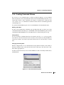
10.1 Creating Plots ..................................................................................................... 153
10.2 Viewing and Manipulating Plots ....................................................................... 154
10.2.1 Selecting Plots .............................................................................................. 155
10.2.2 Panning and Zooming ................................................................................... 156
10.2.3 Labeling and Unlabeling Data Points ............................................................ 156
10.2.4 Selecting and Deselecting Project Entries .................................................... 157
10.2.5 Including and Excluding Project Entries........................................................ 157
viii
Maestro 8.0 User Manual
Contents
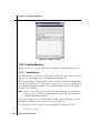
10.3 Editing Plots and Plot Settings ......................................................................... 158
10.3.1 Modifying Plot Attributes ............................................................................... 158
10.3.2 Operating on Plot Series .............................................................................. 159
10.3.3 Changing X and Y Axis Display .................................................................... 160
10.4 Updating Plots to Reflect Project Table Changes ......................................... 162
10.5 Saving Plot Images ............................................................................................. 162
Chapter 11: Surfaces ....................................................................................................... 163
11.1 Generating Surfaces ........................................................................................... 163
11.1.1 Surface Generation Controls......................................................................... 163
11.1.2 Molecular Surfaces ....................................................................................... 165
11.1.3 Extended Radius Surfaces............................................................................ 165
11.1.4 van der Waals Surfaces ................................................................................ 167
11.2 Hydrophobic/philic Surfaces............................................................................. 167
11.2.1 Background ................................................................................................... 167
11.2.2 Mapping Algorithm ........................................................................................ 169
11.2.3 Specifying a Structure to Be Mapped ........................................................... 169
11.2.4 Defining the Mapping Box ............................................................................. 169
11.2.5 Running the Job............................................................................................ 170
11.2.6 Viewing the Site Map Surface ....................................................................... 171
11.3 Importing Surface or Volume Files .................................................................. 171
11.4 The Surface Table Panel..................................................................................... 172
11.4.1 Importing, Modifying, and Deleting Surfaces ................................................ 173
11.4.2 Changing the Appearance of the Surface .................................................... 174
11.4.3 Exporting Surfaces........................................................................................ 176
Chapter 12: Customizing Maestro .......................................................................... 177
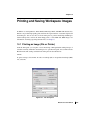
12.1 Changing and Saving Panel Layout ................................................................. 177
12.2 Setting Preferences ............................................................................................ 178
12.2.1 Setting Project Preferences .......................................................................... 178
12.2.2 Specifying a Default Working Directory ........................................................ 180
12.2.3 Customizing Atom Label Appearance........................................................... 181
Maestro 8.0 User Manual
ix
Contents
12.2.4 Setting Workspace Preferences.................................................................... 182
12.2.5 Setting File Suffix Preferences...................................................................... 185
12.2.6 Setting Builder Preferences .......................................................................... 186
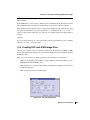
12.2.7 Setting Job Preferences................................................................................ 187
12.3 Customizing Resources ..................................................................................... 189
12.4 Changing the Workspace Appearance ............................................................ 189
12.4.1 Showing or Hiding Controls and Displays ..................................................... 189
12.4.2 Setting the Background Color ....................................................................... 190
12.5 Setting Up 3D Viewing ........................................................................................ 190
12.5.1 Specifying a Stereo Viewing Method ............................................................ 190
12.5.2 Enabling Perspective..................................................................................... 191
12.5.3 Enabling Fog ................................................................................................. 191
12.5.4 Depth Cues ................................................................................................... 193
Chapter 13: Scripting in Maestro ............................................................................. 195
13.1 The Scripts Menu ................................................................................................ 195
13.1.1 Installing Scripts and Macros ........................................................................ 195
13.1.2 Obtaining Scripts from the Script Center ...................................................... 197
13.1.3 Managing Scripts .......................................................................................... 198
13.2 Customization Using Python Scripts .............................................................. 198
13.3 Customization Using Command Scripts......................................................... 199
13.3.1 Command History ......................................................................................... 200
13.3.2 Building a Command Script .......................................................................... 200
13.3.3 Saving a Command Script ............................................................................ 200
13.3.4 Opening Existing Command Scripts ............................................................. 201
13.3.5 Running and Stopping Scripts ...................................................................... 201
13.3.6 Customizations You Can Perform With a Script............................................ 201
13.4 Creating Command Aliases............................................................................... 203
13.5 Creating Macros .................................................................................................. 204
13.5.1 Named Macros.............................................................................................. 204
13.5.2 Function Key Macros .................................................................................... 205
x
Maestro 8.0 User Manual
Contents
Chapter 14: Printing and Saving Workspace Images ............................... 207
14.1 Printing an Image (File or Printer) .................................................................... 207
14.2 Creating TIFF and JPEG Image Files ............................................................... 209
Chapter 15: Help ................................................................................................................. 213
15.1 The Help Menu ..................................................................................................... 213
15.2 Maestro Online Help ........................................................................................... 214
15.3 Context-Sensitive Help ....................................................................................... 215
15.4 Manuals ................................................................................................................. 215
15.5 The Schrödinger Web Site ................................................................................. 216
15.6 Technical Support ............................................................................................... 217
Appendix A: The Maestro File Format ................................................................. 219
A.1 Basic File Description ......................................................................................... 219
A.2 Data Blocks ........................................................................................................... 219
A.3 Compressed Format ........................................................................................... 221
A.4 Data Item Names .................................................................................................. 221
A.5 Example Maestro File .......................................................................................... 221
Appendix B: Atom Types ............................................................................................... 225
Appendix C: Substructure Notation ....................................................................... 233
C.1 Atom and Bond Types ........................................................................................ 233
C.2 Ring closure .......................................................................................................... 235
C.3 Chain branching .................................................................................................. 235
C.4 Optional atoms ..................................................................................................... 236
C.5 Special Cases ....................................................................................................... 236
C.6 Examples ............................................................................................................... 237
Maestro 8.0 User Manual
xi
Contents
C.7 Formal Charge Extensions ................................................................................ 238
C.8 Atom Type Equivalence Labels ......................................................................... 239
C.9 Differences between mmsubs and bmin notations ....................................... 240
C.10 Related Files ....................................................................................................... 240
Appendix D: Utilities ......................................................................................................... 241
D.1 Structure Conversion .......................................................................................... 241
D.1.1 Conversions to and From MacroModel Format .............................................. 241
D.1.2 Conversions to and From Mol2 Format .......................................................... 242
D.1.3 Conversions to and From PDB Format: pdbconvert ............................................243
D.1.4 Conversions to and From SD Format: sdconvert............................................ 245
D.1.5 Conversions to and from SMILES: uniquesmiles ........................................... 246
D.2 Structure Extraction ............................................................................................ 247
D.2.1 maesubset ...................................................................................................... 247
D.2.2 sdsubset ........................................................................................................ 248
D.2.3 propfilter.......................................................................................................... 248
D.2.4 ligfilter ............................................................................................................. 249
D.3 Display of Properties ........................................................................................... 251
D.4 Structure Preparation: applyhtreat ................................................................... 251
D.5 Project Management ........................................................................................... 253
D.5.1 project_convert .............................................................................................. 253
D.5.2 project_create................................................................................................. 253
D.5.3 project_append............................................................................................... 254
D.6 Unique Names ...................................................................................................... 255
Appendix E: Customizing Colors ............................................................................. 257
E.1 Color Definitions .................................................................................................. 257
E.2 Color Schemes ..................................................................................................... 258
E.3 Color Ramps ......................................................................................................... 259
xii
Maestro 8.0 User Manual
Contents
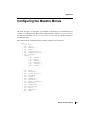
Appendix F: Configuring the Maestro Menus ................................................. 261
Appendix G: Customizing the Online Help ....................................................... 263
Glossary .................................................................................................................................... 265
Index ............................................................................................................................................ 267
Maestro 8.0 User Manual
xiii
xiv
Maestro 8.0 User Manual
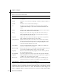
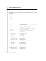
Document Conventions
In addition to the use of italics for names of documents, the font conventions that are used in
this document are summarized in the table below.
Font
Example
Use
Sans serif
Project Table
Names of GUI features, such as panels, menus,
menu items, buttons, and labels
Monospace
$SCHRODINGER/maestro
File names, directory names, commands, environment variables, and screen output
Italic
filename
Text that the user must replace with a value
Sans serif
uppercase
CTRL+H
Keyboard keys
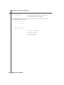
In descriptions of command syntax, the following UNIX conventions are used: braces { }
enclose a choice of required items, square brackets [ ] enclose optional items, and the bar
symbol | separates items in a list from which one item must be chosen. Lines of command
syntax that wrap should be interpreted as a single command.
File names and paths are generally represented with the UNIX conventions. If you are running
on Windows, replace the forward slash character / with the backslash character \.
In this document, to type text means to type the required text in the specified location, and to
enter text means to type the required text, then press the ENTER key.
References to literature sources are given in square brackets, like this: [10].
Maestro 8.0 User Manual
xv
xvi
Maestro 8.0 User Manual
Maestro User Manual
Chapter 1
Chapter 1:
Maestro Overview
Maestro is the graphical user interface (GUI) for all of Schrödinger’s computational programs:
CombiGlide, Epik, Glide, Impact, Jaguar, Liaison, LigPrep, MacroModel, Phase, Prime,
QikProp, QSite, SiteMap, and Strike. It contains tools for building, displaying, and manipulating chemical structures; for organizing, loading and storing these structures and associated
data; and for setting up, submitting, monitoring, and visualizing the results of calculations on
these structures. Maestro’s Job Control facility manages jobs submitted from Maestro and
from the command line to both local and remote hosts. Maestro can be run locally and submit
jobs to any host that you have access to.
The Maestro interface uses the OpenGL graphics tools, and can take advantage of hardware
graphics capabilities, including stereo viewing capabilities. Maestro runs on SGI, Linux, and
Windows platforms. For information on Maestro requirements, software and hardware, see
Chapter 2 of the Installation Guide. For information on configuring stereo viewing, see
Section 12.5 on page 190.
This manual contains an introduction to the Maestro graphical user interface (GUI) and a
description of how to use Maestro’s settings, panels, and features to build, import, and manipulate molecular structures. No prior knowledge of Maestro is assumed. If you cannot find the
information you are looking for in this document, see the Maestro online help. For help with
preparing and starting computations, see the user manual for the related product.
This chapter provides an overview of Maestro—the general interface design, Maestro projects,
Maestro workflow, and running jobs from Maestro.
1.1
General Interface Design
The Maestro interface design follows most common interface conventions, but it has some
characteristics that are unique. The general operation of the Maestro interface is described in
this section. Specific features are described in the relevant sections or chapters.
1.1.1
Maestro Windows
Maestro is based on a main window, from which you can open a range of secondary windows
for the performance of various tasks. The main window is described in detail in Chapter 2.
Maestro 8.0 User Manual
1
Chapter 1: Maestro Overview
Most of the windows that are opened from Maestro are amodal, and are called panels. More
than one panel can be open at any given time, and a panel need not be closed for an action to be
carried out.
Maestro also has dialog boxes, most of which are modal: you must click OK to carry out the
action and you cannot open any of the panels while the dialog box is open. There are also some
dialog boxes that allow you to carry out limited operations in the Workspace or in a panel. The
online help is displayed in a browser, so it is not limited by the modality of the dialog boxes.
1.1.2
Mouse Functions
Maestro supports common mouse functions:
• The left button is used for selecting: choosing menu items, clicking buttons and selecting
objects. This button is also used for resizing and moving panels. In the description of
mouse actions, “click” always means left-click.
• The right button is used for opening a shortcut (context-sensitive) menu, where these
menus are available.
• Shift-click is used to select a contiguous range of items in a list, and control-click is used
to select and deselect a single item in a list without affecting the selection of other items.
• Dragging operations are supported. For instance, in the Workspace, dragging selects multiple objects. In the Project Table, dragging selected entries allows you to reposition the
entries; dragging a column heading moves the column; dragging with the middle mouse
button on the boundary of a row or column resizes the row or column.
• The mouse wheel is supported for scrolling vertically in tables, lists, and text areas. In
lists, scrolling is equivalent to using the UP ARROW and DOWN ARROW keys. In tables,
the table scrolls one line at a time, or with the SHIFT key, one page at a time.
There are also specialized mouse functions in the Workspace, which are described in
Section 2.8 on page 22.
If you have the handedness on your mouse set to “left”, the mouse functions are the mirror
image of those described: the right mouse button is used for picking, and the left button is used
for shortcut menus.
If you have a two-button mouse, ensure that it is configured for three-button mouse simulation.
Then the middle mouse button is simulated by pressing or holding down both buttons.
2
Maestro 8.0 User Manual
Chapter 1: Maestro Overview
1.1.3
Keyboard Shortcuts
Maestro supports keyboard shortcuts in some of its panels, including the main window. These
shortcuts are documented with the relevant panel. The shortcut keys do not work if you have
NUM LOCK, CAPS LOCK, or SCROLL LOCK enabled.
The PAGE UP, PAGE DOWN, HOME, and END keys are supported in tables.
1.2
Maestro Workflow
The main Maestro workflow involves performing actions on the displayed structures, to change
the appearance of the structures or to change the content of the structures. In many cases, you
will want to change only a part of the structure, which involves selecting the atoms that you
want to change. (The workflow for a product, which is supported by Maestro panels, involves
setting up and running jobs.)
Maestro has two ways of performing an action on a structure or a part of a structure:
• Choose an action first and then select the atoms to apply the action to.
Actions are usually chosen either from a toolbar button menu or by opening a panel and
selecting options.
• Select atoms first and then choose an action to perform on them.
Actions can be performed by opening a panel, selecting options and clicking the Selection button, or by choosing an item from the selection shortcut menu. See Section 2.7 on
page 19 for more details on this shortcut menu.
Maestro’s atom selection tools provide you with a range of options for selecting single atoms,
entire structural units, or complex combinations of atom sets. These tools are described in
detail in Chapter 5.
1.3
Maestro Projects
When you use Maestro, you are always working within a project. A project is a collection of
chemical structures and their associated data. These structures and their data are organized into
entries, each of which can consist of multiple molecules and their properties. The project is
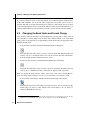
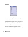
represented in the Project Table, which displays an ordered list of entries and any associated
data. You can open the Project Table panel by choosing Show Table from the Project menu, or
by clicking the Open/Close Project Table button on the toolbar.
Maestro 8.0 User Manual
3
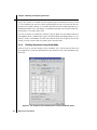
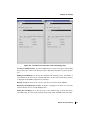
Chapter 1: Maestro Overview
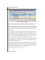
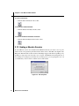
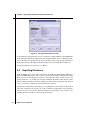
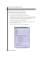
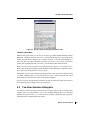
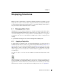
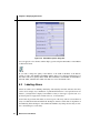
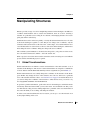
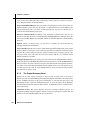
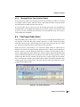
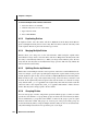
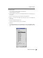
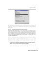
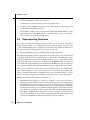
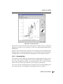
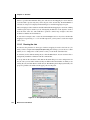
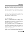
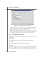
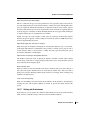
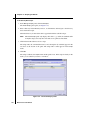
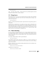
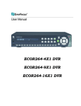
Figure 1.1. The Project Table panel.
If you do not specify a project when you start Maestro, Maestro creates a scratch project. You
can work in a scratch project, but you must save it in order to use it in future sessions.
Entries are represented by rows in the Project Table. Each row contains the row number, the
title, the entry’s Workspace inclusion state (the In column), a button to open the Surfaces panel
if there are surfaces associated with the entry, the entry name, and any properties associated
with the entry. If there are no surfaces associated with any entry, the Surf column of the Project
Table is empty.
You control which entries are displayed in the Workspace from the Project Table. You can use
entries as input for most of the computational programs. You can select entries as input for the
ePlayer, which displays the selected structures in sequence. You can duplicate, combine,
rename, split, and sort entries; create properties for entries, import structures as entries, and
export entries in various formats. Although the Project Table does not have spreadsheet capabilities, you can export properties to and import properties from a spreadsheet.
When you build molecules in the Workspace, they constitute a scratch entry until you choose
to save the structures as project entries. The scratch entry is not saved with the project unless
you explicitly add it to the project. However, you can use a scratch entry as input for some jobs,
and the results can be incorporated.
For products that have wizard-based interfaces (CombiGlide, Phase, and Prime), data is stored
inside the project, grouped as entities called “runs”. Output from each step is incorporated into
the next step and stored in the project, but not via the Project Table. The data in the runs can
include structural data, but do not make use of the Project Table directly. Instead, structures can
be copied to and from the Project Table at various points in the run.
More information on projects is given in Chapter 8.
4
Maestro 8.0 User Manual
Chapter 1: Maestro Overview
1.4
Job Launching and Incorporation
Maestro’s job launching and incorporation capabilities are designed to make it easy to manage
multiple structures and their passage though multiple computational programs, without having
to deal with the details of the file system. The running of jobs is handled by the Job Control
facility, which is described in detail in the Job Control Guide.
Maestro has dedicated panels for each product for preparing and submitting jobs. To use these
panels, choose the appropriate product and task from the Applications menu and its submenus.
Set the appropriate options in the panel, then click Start to open the Start dialog box and set
options for running the job. See Section 4.2 of the Job Control Guide for a detailed description
of the options in the Start dialog box. When you have finished, click Start to launch the job and
open the Monitor panel. Note that most jobs run locally are automatically run at low priority so
that they do not significantly affect the performance of Maestro. Exceptions are noted in this
manual.
Input files for the job are written to Maestro’s current working directory unless otherwise specified (see Section 12.2.2 on page 180). This directory can be changed by choosing Change
Directory from the Maestro menu and navigating to the new directory in the Change Directory
dialog box, or entering the command cd path in the command input area of the main window.
Once a job is launched, the Monitor panel is automatically displayed and job progress is posted
to the monitor window. You may cease or resume monitoring at any time, and you can monitor
any currently running job. If a job finishes while it is being monitored, its output is incorporated into the current project, according to the settings used to launch the job. If a job that is not
currently being monitored finishes successfully, you must select it in the Monitor panel and
click Monitor to incorporate the results. Multiple structures are incorporated as entry groups.
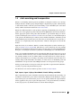
For the programs that do not incorporate results, the output files are placed in the file I/O directory that you specify using the Preferences panel.
For information on Job Control and incorporation, see the Job Control Guide.
Epik, Impact, Jaguar, LigPrep, MacroModel, PrimeX, QikProp, and QSite
These computational programs, which have been fully integrated with the Project Facility, can
use Maestro structure files, project entries and structures displayed in the Workspace as input,
and can incorporate job results into the project. You can specify whether the output structures
will be appended to the project, replace the input entries, or be ignored when the job finishes.
As the job progresses, any interim structures are shown in the Workspace.
Maestro 8.0 User Manual
5
Chapter 1: Maestro Overview
Some of these computational programs have additional capabilities:
• Epik and LigPrep jobs can read structures from external files. This choice of structural
input has no connection with a Maestro project, so the output is required to be written to
an external file.
• Jaguar maintains its own input and output files and directory structure. These files contain
structural and other information.
Glide, Liaison, and SiteMap
These computational programs have differing degrees of integration with the Project Facility.
Glide can use selected entries from the Project Table as input for docking, but does not incorporate the results. The pose files that are generated can be viewed using the Project Table tools
as well as in the Glide Pose Viewer. Liaison takes input from structures in the Workspace or the
Project Table, and the results are automatically appended to the project. Protein preparation
uses the Workspace structure as input and the resulting structure is incorporated. SiteMap uses
the Workspace as the source of input, and incorporates the results into the project.
Phase
The three stages of Phase workflow behave differently in relation to the Maestro project.
Development of a pharmacophore model uses a wizard-based interface. It reads structures
from the project and stores information in the project, but does not incorporate results into the
Project Table. Database preparation has no connection to a Maestro project. The database
search automatically adds the hits to the Project Table: there are no other incorporation
options.
Prime
Prime’s Protein Structure Prediction uses a wizard-based interface. The input is a sequence
rather than a structure, though the sequence can be taken from a structure in the Workspace. At
the final step, the structures can be copied into the Project Table. The standalone Refinement
facility is similar to MacroModel and QikProp: it takes the structure in the Workspace as input
and incorporates the results into the Project Table according to the selected option.
CombiGlide
Like Prime and Phase, CombiGlide adds data to a project in the form of “runs”, but structures
are not incorporated into the Project Table unless explicitly requested.
MCPRO+
MCPRO+ does not use input from the Project Table or the Workspace, but reads the input from
files. However, the results can be incorporated into the project.
6
Maestro 8.0 User Manual
Chapter 1: Maestro Overview
Strike
Strike is intimately linked with the Project Facility, uses descriptor data from single or multiple
Project Table entries as input, and automatically incorporates job results into the project
without overwriting existing data. Workspace and selected entry molecules are used to determine which molecules are used by Strike for a given calculation. Job output can be monitored
in the Monitor panel. Jobs can be run on any machine listed within the schrodinger.hosts
file. Models generated by Strike can be imported from one project to another or exported for
use at the command line.
1.5
Citing Maestro in Publications
The use of this product should be acknowledged in publications as:
Maestro, version 8.0, Schrödinger, LLC, New York, NY, 2007.
Maestro 8.0 User Manual
7
8
Maestro 8.0 User Manual
Maestro User Manual
Chapter 2
Chapter 2:
The Maestro Main Window
This chapter describes how to start and end a Maestro session, and gives a detailed description
of the main window and its functions.
2.1
Starting Maestro
The mechanism for starting Maestro is different for UNIX and Windows hosts. This mechanism is described for each of these host types in the following subsections.
When Maestro starts, it reads resource files that define your preferences from your preferences
directory. For information on the location of this directory and on setting preferences, see
Chapter 12. Any resource files that it does not find in this location it reads from the resource
subdirectory in the Schrödinger software installation, maestro-vversion/data/res, where
version is the 5-digit Maestro version number. The resource files and preferences are saved in
your preferences directory when you quit Maestro.
If you are starting a new release of Maestro for the first time, the preferences and resource files
are copied from the location for the previous release. Your preferences are therefore preserved
for the new version of Maestro. If you see warnings on startup, it is likely that a customization
is no longer valid, due to definitions changing between releases. For more information on
defining resources, see Section 12.3 on page 189.
The default project that Maestro starts with is a scratch project (see Section 1.3 on page 3 for
information on scratch projects). This project is stored in the directory specified by the
TEMP_PROJECT environment variable. The default location is
UNIX:
$HOME/.schrodinger/tmp
Windows:
%USERPROFILE%\.schrodinger\tmp
If space is limited on your home file system, consider setting TEMP_PROJECT to a directory in
which you have plenty of space to avoid filling the home file system.
On UNIX, the directory from which Maestro was started is called the launch directory. On
Windows, this directory is the directory specified by the USERPROFILE environment variable,
which is usually set to C:\Documents and Settings\username. The launch directory
becomes Maestro’s current working directory. For information on changing the current
working directory, see Section 1.4 on page 5.
Maestro 8.0 User Manual
9
Chapter 2: The Maestro Main Window
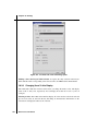
2.1.1
Starting Maestro on a Windows Host
To start Maestro, double-click the Maestro icon on the desktop, or use the Start menu. Maestro
is in the Schrödinger submenu. This submenu can also be used to open the release notes and
the documentation index in your browser.
To start Maestro with a specific project, double-click the zipped project. Zipped projects have a
.prjzip extension, and are read-only. To replace the zipped project, you must first save it,
then zip it, then copy it over the old project. Zipped projects can also be linked to a web page:
clicking on the link to project in your browser opens the project in Maestro.
2.1.2
Starting Maestro on a UNIX Host
Before starting Maestro, you must set the SCHRODINGER environment variable to point to the
installation directory, by entering the following command in a terminal window:
csh/tcsh:
setenv SCHRODINGER installation-directory
bash/ksh:
export SCHRODINGER=installation-directory
You might also need to set the DISPLAY environment variable, if it is not set automatically
when you log in. To determine if you need to set this variable, enter the command:
echo $DISPLAY
If the response is a blank line, set the variable by entering the following command:
csh/tcsh:
setenv DISPLAY display-machine-name:0.0
bash/ksh:
export DISPLAY=display-machine-name:0.0
For local display, you should omit display-machine-name.
Online help in Maestro is displayed in a browser. The default browser is Firefox on Linux and
Netscape on SGI. You can change the browser used by setting the environment variable
MAESTRO_HELP_BROWSER to the full path to the browser. Manuals can also be opened from
Maestro. These are opened in a PDF viewer. The default viewer is Adobe Reader (acroread),
with a fallback to xpdf. You can change the PDF viewer used by setting the environment variable SCHRODINGER_PDF_VIEWER to the full path to the viewer.
After you set the SCHRODINGER and DISPLAY environment variables, you can start Maestro
using the command:
$SCHRODINGER/maestro [options] [filename]
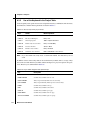
The options for the maestro command are listed in Table 2.1. The optional filename specifies a
file in Maestro, SD, or MacroModel format.
10
Maestro 8.0 User Manual
Chapter 2: The Maestro Main Window
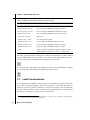
Table 2.1. Options for the maestro command.
Option
Description
-b PDB-file
Read a PDB file. Cannot be used with -m.
-c command-script
Run the specified Maestro command script when Maestro starts.
-h
Print a usage message, but do not start Maestro.
-m filename
Load structures from a Maestro (.mae), compressed Maestro (.mae.gz or
.maegz) or MacroModel (.dat) structure file. Cannot be used with -b.
The -m can be omitted if this option is at the end of the option list.
-p project
Load the specified Maestro project. Project names normally end in .prj, or
.prjzip or .prj.zip for zipped projects.
-s number
Specify the first structure to load when a Maestro file is loaded.
-t number
Specify the total number of structures to load when a Maestro file is loaded.
-v
Display the Maestro version number, but do not start Maestro.
-I
Display extra information about X visual settings when Maestro starts.
-SGL
Use the Schrödinger-supplied OpenGL library. The default is to use the
system OpenGL library.
-nosoftaa
SGI only. On some SGIs anti-aliasing (smoothing) for line widths greater
than 1 is only possible in a software implementation. On certain machines
there may be a performance penalty when using the software implementation. Use this option to disable software anti-aliasing.
-nosplash
Disable display of the splash screen when starting Maestro.
-nosurfdisplaylist
Don’t use display lists for surface rendering (required to fix display problems on some hardware platforms).
2.2
The Main Window
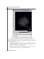
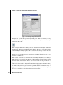
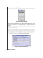
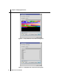
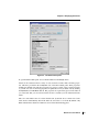
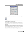
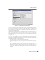
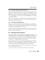
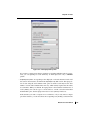
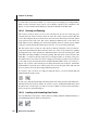
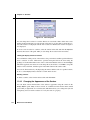
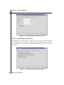
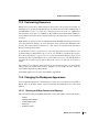
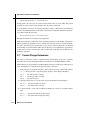
The Maestro main window is shown in Figure 2.1. The following main window components
are always visible:
• Title bar—displays the project name and the current working directory
• Auto-Help—automatically displays context-sensitive help
• Main menu bar—provides access to panels
• Workspace—displays molecular structures and other 3D graphical objects, such as surfaces and Phase hypotheses. Information on a single project entry can also be displayed
in the top left corner—see Section 12.2.4 on page 182.
Maestro 8.0 User Manual
11
Chapter 2: The Maestro Main Window
Figure 2.1. The Maestro main window, showing all window components.
The following main window components can be displayed or hidden by choosing the component from the Display menu. Your choice of which main window components are displayed is
persistent between Maestro sessions.
• Clipping planes window—displays a small, top view of the Workspace that shows the
clipping planes and viewing volume indicators. This feature is hidden by default. To display it, choose Clipping Planes from the Display menu.
• Toolbar—contains buttons for many common tasks and also provides tools for displaying and manipulating structures, as well as organizing the Workspace.
12
Maestro 8.0 User Manual
Chapter 2: The Maestro Main Window
• Status bar—displays information about a particular atom, about structures in the Workspace, or about the contents of the Workspace and job status.
• Sequence viewer—shows the sequences for proteins displayed in the Workspace. This
feature is hidden by default. To display it, choose Sequence Viewer from the Display
menu.
• Command input area—provides a place to enter Maestro commands. This feature is
hidden by default. To display it, choose Command Input Area from the Display menu.
When a distinction between components in the main window and those in other panels is
needed, the term main is applied to the main window components (e.g., main toolbar).
You can expand the Workspace to occupy the full screen, by pressing CTRL+=. All other
components and panels are hidden. To return to the previous display, press CTRL+= again.
The following sections describe some of these main window components in more detail.
2.3
The Menu Bar
The menus on the main menu bar provide access to panels, allow you to enter commands, and
control the appearance and contents of the Workspace. The main menus are as follows:
• Maestro—save or print Workspace images, set preferences, change directories, enter system commands, save or load a panel layout, set up Maestro command aliases, and quit
Maestro.
• Project—open and close projects, import and export structures, make a snapshot, and
annotate a project. These actions can also be performed from the Project Table panel. For
more information on projects, see Chapter 8.
• Edit—undo actions, build and modify structures, define command scripts and macros,
and find atoms in the Workspace.
• Display—control the display of the contents of the Workspace, arrange panels, and display or hide main window components.
• Tools—group atoms; measure, align, and superimpose structures; assign structural features; and view and visualize data.
• Applications—set up, submit, and monitor jobs for Schrödinger’s computational programs. Some products have a submenu from which you can choose a specific task.
• Workflows—set up, submit, and monitor jobs for workflows (also known as “solutions”).
These workflows generally use more than one product.
• Scripts—manage, install, and run scripts. For details, see Section 13.1 on page 195.
Maestro 8.0 User Manual
13
Chapter 2: The Maestro Main Window
• Help—display various kinds of documentation, including online help, Balloon Help
(tooltips), manuals, FAQs, information about Maestro and other Schrödinger products.
The functions of the items on the menus are described in detail in later chapters of this manual.
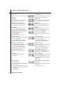
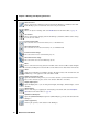
2.4
The Toolbar
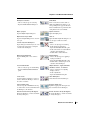
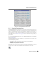
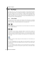
The main toolbar contains three kinds of buttons for performing common tasks:
Action—Perform a simple task, like clearing the Workspace.
Display—Open or close a panel or open a dialog box, such as the Project
Table panel.
Menu—Display a button menu. These buttons have a triangle in the lower
right corner.
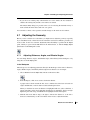
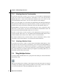
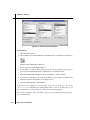
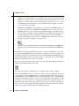
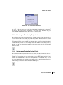
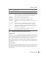
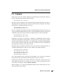
There are four types of items on button menus, and all four types can be on the same menu (see
Figure 2.2):
• Action—Perform an action immediately.
• Display—Open a panel or dialog box.
• Object types for selection—Choose Atoms, Bonds, Residues, Chains, Molecules, or
Entries, then click on an atom in the Workspace to perform the action on all the atoms in
that structural unit.
The object type is marked on the menu with a red diamond and the button is indented to
indicate the action to be performed.
• Other setting—Set a state, choose an attribute, or choose a parameter type and click on
atoms in the Workspace to act upon that parameter.
The toolbar buttons are described below. Many of the features are described in later chapters.
object type
display
Figure 2.2. Examples of button menus.
14
Maestro 8.0 User Manual
other setting:
parameter type
action
Chapter 2: The Maestro Main Window
Workspace selection
– Choose an object type for selecting
– Open the Atom Selection dialog box
Undo/Redo
Undo or redo the last action. Same as
Undo on the Edit menu. Changes to an
arrow pointing in the opposite direction
when an Undo has been performed, indicating that its next action is Redo.
Open a project
Open the Open Project dialog box.
Import structures
Open the Import panel.
Open/Close Project Table
Open the Project Table panel or close it if
it is open.
Save as
Open the Save Project As dialog box, to
save the project with a new name.
Create entry from Workspace
Open a dialog box in which you can create
an entry in the current project using the
contents of the Workspace.
Delete
– Choose an object type for deleting
– Delete hydrogens and waters
– Open the Atom Selection dialog box
– Delete other items associated with the
structures in the Workspace
– Double-click to delete all atoms
Open/Close Build panel
Open the Build panel or close it if it is
open.
Add hydrogens
– Choose an object type for applying a
hydrogen treatment
– Open the Atom Selection dialog box
– Double-click to add hydrogens to all
structures in the Workspace
Local transformation
– Choose an object type for transforming
– Open the Advanced Transformations
panel
Adjust distances, angles, dihedrals,
chiralities, torsions, or rotamers
– Choose a parameter for adjusting
– Display contacts
– Delete adjustments
– Open the Rotamers dialog box
Fit to screen
Scale the displayed structure or selected
atoms to fit into the Workspace and reset
the center of rotation.
Clear Workspace
Clear all atoms from the Workspace
Set fog display state
Choose a fog state. Automatic means fog
is on when there are more than 40 atoms in
the Workspace, off otherwise.
Enhance depth cues
Optimize fogging and other depth cues
based on what is in the Workspace.
Rotate around X axis by 90 degrees
Rotate the Workspace contents around the
X axis by 90 degrees.
Rotate around Y axis by 90 degrees
Rotate the Workspace contents around the
Y axis by 90 degrees.
Maestro 8.0 User Manual
15
Chapter 2: The Maestro Main Window
16
Tile entries
Arrange entries in a rectangular grid in the
Workspace.
Reset Workspace
Reset the rotation, translation, and zoom of
the Workspace to the default state.
Save view
Save the current view of the Workspace:
orientation, location, and zoom.
Restore view
Restore the last saved view of the Workspace: orientation, location, and zoom.
Display only selected atoms
– Choose an object type for displaying
– Double-click to display all atoms
Display only
– Choose a predefined atom category
– Open the Atom Selection dialog box
Also display
– Choose a predefined atom category
– Open the Atom Selection dialog box
Undisplay
– Choose a predefined atom category
– Open the Atom Selection dialog box
Display residues within N angstroms of
currently displayed atoms
– Choose a radius
– Open a dialog box to set a value
Show, hide, or color ribbons
– Choose show or hide ribbons
– Choose a color scheme for coloring ribbons
Draw bonds in wire
– Choose an object type for drawing bonds
in wire representation
– Open the Atom Selection dialog box
– Double-click to apply to all atoms
Draw atoms in CPK
– Choose an object type for drawing bonds
in CPK representation
– Open the Atom Selection dialog box
– Double-click to apply to all atoms
Draw atoms in Ball & Stick
– Choose an object type for drawing bonds
in Ball & Stick representation
– Open the Atom Selection dialog box
– Double-click to apply to all atoms
Draw bonds in tube
– Choose an object type for drawing bonds
in tube representation
– Open the Atom Selection dialog box
– Double-click to apply to all atoms
Color all atoms by scheme
Choose a predefined color scheme
Color residue by constant color
– Choose a color for applying to residues
– Double-click to color all atoms
Label atoms
– Choose a predefined label type
– Delete labels
Label picked atoms
– Choose an object type for labeling atoms
– Open the Atom Selection dialog box
– Open the Composition tab of the Atom
Labels panel
– Delete labels
Display H-bonds
– Choose bond type:
intra—displays H-bonds within the molecule you select
inter—displays H-bonds between the molecule you select and all other atoms in
the Workspace.
– Delete H-bonds
Measure distances, angles, dihedrals,
or coupling
– Choose a parameter for displaying measurements
– Delete measurements
Maestro 8.0 User Manual
Chapter 2: The Maestro Main Window
2.5
The Status Bar
The status bar displays information about the contents of the Workspace or about a particular
atom, depending on where the pointer pauses. If the pointer is not over an atom, information
about the contents of the Workspace is displayed, in the format
Atoms:ma/na
Entries:me/ne
Res:nr
Chn:nc
Mol:nm
Chg:n
where the fields in the display have the following meanings:
Atoms
Entries
Res
Chn
Mol
Chg
Jobs
Number of atoms in the Workspace: ma is the number displayed, na is the total
Number of entries in the Workspace: me is the number displayed, ne is the total
Number of residues nr in the Workspace
Number of chains nc in the Workspace
Number of molecules nm in the Workspace
Total charge n of the Workspace contents
Number of jobs running in the project/Total number of jobs running
If the pointer is over an atom, and the preference to show feedback on atoms is set, the status
bar displays the chain, residue number, element, PDB atom name, formal charge, and a userselected property, in the format
chain:residue number :(element) PDB :charge:"userchoice"
where the fields in the display have the following meanings:
chain
residue
number
element
PDB
charge
userchoice
Chain name
Residue name
Residue number and insertion code
Element
PDB atom name
Formal charge of the atom
Selected Project Table property
The preference to show feedback and the user-selected property can be set in the Workspace
tab of the Preferences panel—see Section 12.2.4 on page 182.
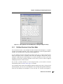
2.6
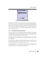
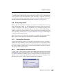
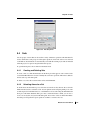
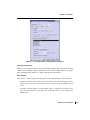
The Sequence Viewer
The sequence viewer displays the sequence of the proteins that are included in the Workspace.
Each chain is displayed on a separate line. If the sequence is longer than a single line, the entire
set of lines is continued below the first set of lines (“wrapped”). The left column of the
Maestro 8.0 User Manual
17
Chapter 2: The Maestro Main Window
sequence viewer displays a label for the sequence, in the format row:pdbID_chainID, where
row is the Project Table row number. The right column displays the actual sequence as a list of
single-letter codes, and also displays the secondary structure assignment, if one is available.
The background colors of the sequences reflect the current coloring scheme for the alpha
carbon in the Workspace. Each residue in the sequence also has a tooltip that gives the residue
name, number, and insertion code.
If the protein has a secondary structure assignment, the assignment is displayed above the
sequence, using the following symbols:
• Helices are displayed as tubes, colored red
• Strands are displayed as arrows, colored cyan
• Loops are displayed as a gray line.
You can select residues in the sequence and perform actions on these residues.
• To select a range of residues, either click the first and shift-click the last, or drag over the
residues.
• To select a single residue, click the residue.
• To add residues to the selection or remove residues from the selection, control-click the
residues.
The selected residues are highlighted as white letters on a black background, and are marked in
yellow in the Workspace.
The sequence viewer and the Workspace are synchronized: selection of atoms in the Workspace selects the corresponding atoms in the sequence viewer, and selection of residues in the
sequence viewer selects them in the Workspace. Likewise, changing the color scheme in the
Workspace changes the color scheme in the sequence viewer, and vice versa. Structural
changes, such as mutating a residue, are also reflected in the sequence viewer.
To zoom in on a residue in the Workspace without selecting it, middle-click the residue in the
sequence viewer.
The sequence viewer has a shortcut menu (right-click and hold), which you can use to perform
various actions on the sequences or the display. If you do not have any residues selected in the
sequence viewer, the sequence viewer shortcut menu is displayed. The items on this menu are
described in Table 2.2. If you have residues selected, the selection shortcut menu is displayed
(see Table 2.3). In this context there is one extra item on the Color Scheme submenu: Proximity.
If you choose this item, the residues within a given distance of the selected residues are colored
orange, and the selected residues are colored red. All others are colored gray. The distance is
specified in the Sequence Viewer - Preferences dialog box, which you open from the sequence
viewer shortcut menu.
18
Maestro 8.0 User Manual
Chapter 2: The Maestro Main Window
Table 2.2. Sequence viewer shortcut menu items.
Menu Item
Action
Hide
Hide the sequence viewer. To redisplay it, use the Display menu.
Color Scheme
Color the sequence with the scheme selected from the submenu. Choose from
None, Color by Chain, Residue Type, Residue Property, Secondary Structure,
Template ID, or Proximity (sequence viewer only).
Font Size
Set the font size for the sequence viewer. Choose Small, Medium, Large, or
Huge from the submenu.
View SSA
Show or hide the secondary structure assignment for the sequence.
Show Displayed
Residues Only
Show only the residues that are displayed in the Workspace.
Align by Residue
Number
Align the sequences in the sequence viewer by residue number. (Does not affect
the alignment of the structures.) This command enables gaps to be displayed in
the sequence viewer.
Exclude Entry
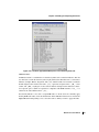
Exclude the entry containing this chain from the Workspace. The chain is
removed from the sequence viewer. If the entry contains multiple chains, all the
chains in the entry are removed from the sequence viewer.
Legend
Open the Sequence Viewer Legend dialog box, which explains the sequence
color schemes.
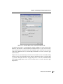
Preferences
Open the Sequence Viewer - Preferences dialog box, in which you can set the
proximity cutoff.
Save Image
Open the Save Sequence Viewer Image dialog box, in which you can select an
image format and save an image of the sequence viewer to a file.
Help
Open the Sequence Viewer help topic in a browser.
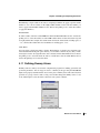
2.7
Shortcut Menus
Some of the main window components have shortcut menus, which you open by right-clicking
and holding over the component. The shortcut menus for the status bar and the command input
area only have two items, Hide, which hides the component, and Help, which displays the relevant help topic. In addition to Hide and Help, the toolbar shortcut menu has Move to Left and
Move to Right, which move the toolbar to the left or right side of the Workspace.
The Workspace has three shortcut menus: one for the Workspace itself (the Workspace shortcut
menu), one for the atoms in the current selection (the selection shortcut menu), and one for
bonds (the bond shortcut menu). The selection shortcut menu is also available from the
sequence viewer. The items on these menus are described in Table 2.3, Table 2.4 and Table 2.5.
Maestro 8.0 User Manual
19
Chapter 2: The Maestro Main Window
The differences in the selection shortcut menu between the Workspace and the sequence
viewer are noted in the table.
When you right-click and hold in the Workspace:
• On an unselected atom, the atom becomes the selection and the selection shortcut menu is
displayed.
• On a selected atom, the selection shortcut menu is displayed.
• On a bond, the two atoms in the bond become the selection and the bond shortcut menu is
displayed.
• On empty space, if there is an atom selection, the selection shortcut menu is displayed,
otherwise the Workspace shortcut menu is displayed.
Table 2.3. Selection shortcut menu items.
20
Menu Item
Action
Invert Selection
Select the unselected atoms and deselect the selected atoms.
Representation
Set the molecular representation to wire frame, ball and stick, CPK, or tube.
Color Scheme
Apply the color scheme from the submenu to the selected atoms.
Labels
Apply the label from the submenu to the selected atoms.
Display
Display the entire molecule or residue containing the selected atoms. This
action is useful if part of the molecule or residue was previously undisplayed.
Display Only
Display only the selected atoms.
Undisplay
Undisplay the selected atoms.
Delete
Delete the selected atoms.
Switch Alternate
Positions
For atoms with partial occupancy, switch between the alternate positions.
(Not available from the sequence viewer.)
Display Alternate
Positions
For atoms with partial occupancy, display all positions. The alternate positions are displayed as ghosts. (Not available from the sequence viewer.)
Set Element
Change the selected atoms to atoms of the element chosen from the submenu.
(Not available from the sequence viewer.)
Insert Gap
Insert a gap to the left of the selected residue. Opens a dialog box in which
you can specify the number of residues to insert. (Not available from the
Workspace.)
Mutate Residue
Change the residues that contain the selected atoms (or the selected residues)
to the type chosen from the submenu.
Maestro 8.0 User Manual
Chapter 2: The Maestro Main Window
Table 2.3. Selection shortcut menu items. (Continued)
Menu Item
Action
Rotamers
Open the Rotamers dialog box to select one of the standard rotamers for the
selected residues.
Exclude Entry
Exclude the entries that contain the selected atoms from the Workspace.
Select Entry in Table
Select the entries that contain the selected atoms in the Project Table.
Fit to Screen
Fit the displayed structure to the Workspace and reset the center of rotation.
Clip
Clip the display to the selected atoms. Moves the clipping planes. (Not available from the sequence viewer.)
Center Electron
Density
Center the displayed electron density map on the centroid of the selected
atoms. Used for PrimeX. (Not available from the sequence viewer.)
Transform
Perform a local transformation. (Not available from the sequence viewer.)
Help
Open the Shortcut Menus help topic in a browser.
Table 2.4. Workspace shortcut menu items.
Menu Item
Action
Background Color
Set the Workspace background color to black, white, gray, or blue.
Print
Open the Print panel to print an image of the Workspace or create a postscript
file of the Workspace.
Save Image
Open the Save Image panel to save an image of the Workspace in TIFF or JPEG
format.
Save View
Save the current view of the Workspace: orientation, location, and zoom.
Restore View
Restore the last saved view of the Workspace: orientation, location, and zoom.
Fit to Screen
Fit the displayed structure to the Workspace and reset the center of rotation.
Create Entry from
Workspace
Create a Project Table entry from the Workspace.
Clear Workspace
Clear the Workspace.
Delete
Delete labels, measurements, or adjustments.
Help
Open the Shortcut Menus help topic in a browser.
Maestro 8.0 User Manual
21
Chapter 2: The Maestro Main Window
Table 2.5. Bond shortcut menu items.
Menu Item
Action
Order
Set the bond order to zero, one, two, or three.
Measure
Measure the bond length and display it. The measurement is added to the list in the
Measurements panel.
Adjust
Adjust the bond length or the dihedral angle around this bond.
Delete
Delete the bond.
2.8
Mouse Functions
The Workspace has special uses for the middle and right mouse buttons. These are used on
their own and in combination with the SHIFT and CTRL keys to perform common operations
such as rotation, translation, centering, and zooming. See the table below for a summary and
Chapter 7 for more detailed information.
Table 2.6. Mapping of Workspace operations to mouse actions.
Mouse Button
Motion
Action
Left
click, drag
Select
Left
drag
Quick Torsion adjustment and adjustment of distance, angle, dihedral (see
Section 4.7.1 on page 57)
click, drag
Toggle the selection
drag
Rotate about X and Y axes
Left
Keyboard
SHIFT
Middle
22
Middle
SHIFT
drag vertically
Rotate about X axis
Middle
SHIFT
drag horizontally
Rotate about Y axis
Middle
CTRL
drag horizontally
Rotate about Z axis
Middle
SHIFT + CTRL
drag horizontally
Zoom
Right
click
Spot-center on selection
Toggle selection
Right
click and hold
Display shortcut menu
Right
drag
Translate in the X-Y plane
Right
SHIFT
drag vertically
Translate along the X axis
Right
SHIFT
drag horizontally
Translate along the Y axis
Maestro 8.0 User Manual
Chapter 2: The Maestro Main Window
Table 2.6. Mapping of Workspace operations to mouse actions. (Continued)
Mouse Button
Keyboard
Motion
Action
Right
CTRL
drag horizontally
Translate along the Z axis
Middle & Right
drag horizontally
Zoom
Wheel
scroll
Zoom
In any adjust mode, do adjustment
Wheel
CTRL
scroll
Adjust isovalue of electron density
map (PrimeX)
In clipping planes window, move clipping planes in opposite directions
Wheel
SHIFT
scroll
In clipping planes window, move clipping planes in the same direction
2.9
Shortcut Keys
Some frequently used operations in the main window have been assigned shortcut key combinations. The shortcuts, their functions, and their menu equivalents are listed in Table 2.7.
Shortcut keys in the Project Table panel and the Plot panel are listed in the chapters that
describe those panels. In addition to the shortcut keys listed below, there are a set of keys that
can be used in either the Workspace or the Project Table. Most of these keys are for actions in
the Project Table.
Note:
If Num Lock, Caps Lock, or Scroll Lock is enabled, the shortcut keys do not work.
Table 2.7. Shortcut keys in the Maestro main window.
Keys
Action
Equivalent Menu Choice
CTRL+B
Open Build panel
Edit > Build
CTRL+C
Create entry
Project > Create Entry From Workspace
CTRL+E
Open Command Script Editor panel
Edit > Command Script Editor
CTRL+H
Display default help topic
Help > Help
CTRL+I
Open Import panel
Project > Import Structures
CTRL+M
Open Measurements panel
Tools > Measurements
CTRL+N
Create a new project
Project > New Project
CTRL+O
Open an existing project
Project > Open Project
CTRL+P
Print Workspace image
Maestro > Print
Maestro 8.0 User Manual
23
Chapter 2: The Maestro Main Window
Table 2.7. Shortcut keys in the Maestro main window. (Continued)
Keys
Action
Equivalent Menu Choice
CTRL+Q
Quit Maestro
Maestro > Quit
CTRL+S
Open Sets panel
Tools > Sets
CTRL+T
Open Project Table panel
Project > Show Table
CTRL+W
Close project
Project > Close Project
CTRL+Z
Undo/Redo last command
Edit > Undo/Redo
CTRL+=
Enter and exit full screen mode
(Workspace occupies full screen)
None
2.10 Finding Objects in the Workspace
If you want to find an atom, molecule, residue, chain, or other group of atoms in the Workspace, you can do so in the Find Atoms panel, which you open from the Edit menu. All
instances of the object that match are located.
2.10.1 Specifying the Search Object
To search by atom, by residue, by chain, by molecule, or by means of an ASL expression,
choose the corresponding option in the Find types section. For each of these choices, a set of
controls is presented to define the search method and the object to search for. The use of these
controls is described below.
Atom
Choose By Number or By Name from the Find Method option menu, then type the atom
number or atom name in the text box.
Residue
Type the residue number in the Residue number text box. You can also specify the chain name
and insertion code in the corresponding text boxes, but these are optional. If the PDB chain
name is not specified, all the residues with the specified residue number (and insertion code if
specified) will be found. If the insertion code is not specified, all the residues with the specified
residue number (and PDB chain name if specified) will be found.
Chain
Type the PDB chain name in the text box.
24
Maestro 8.0 User Manual
Chapter 2: The Maestro Main Window
Figure 2.3. The Find Atoms panel
Molecule
Type the molecule number in the text box.
ASL
Use the standard picking tools in the Select atoms to find section to define the ASL expression.
This is useful for setting up a substructure to find, for example.
2.10.2 Presentation of the Found Objects
Five options are available for identifying the found objects in the Workspace. Any combination
of these options may be selected.
Select found atoms
The found atoms becomes the atom selection.
Label atoms
The objects found are labeled with the atom number if the search object was atoms; chain
name, residue number, and insertion code for residues; PDB chain name for chains; and molecule number for molecules. If the atoms are already labeled, the atom will be labeled with a
string that is the union of the existing label and the find label. The labels can be cleared by
deselecting this option.
Maestro 8.0 User Manual
25
Chapter 2: The Maestro Main Window
Figure 2.4. The Workspace showing a found residue.
Mark principal atoms
A colored arrow (or cube if the molecular representation is CPK or Ball & Stick) is used to
mark the found the principal atoms (or the first atoms) of the found residues, chains or molecules. The color of arrows or cubes reflect the type of object found: yellow for atoms, green for
residues, pink for chains and blue for molecules. The markers can be cleared by deselecting
this option.
Center
The structure is centered on the found atom when finding atoms, on the CA atom when finding
residues, or on the found atom that is the closest to the centroid of the found atoms otherwise.
Zoom
The view is zoomed in to the found atoms.
2.10.3 Performing the Search
Click Find to find the desired object. The Number of matches text field shows the number of
matched objects and the total number of objects in the Workspace.
If you searched for an atom or a residue by number, you can step through the atoms or residues
by clicking Next or Previous, or by pressing the N or P keys. You can change the size of the
26
Maestro 8.0 User Manual
Chapter 2: The Maestro Main Window
step by entering a value in the Step size text box: for example, if you wanted to find every tenth
residue from a given starting residue, you would enter 10 in the text box.
2.11 Undoing Workspace Operations
There are two classes of operations in the Workspace: operations that act on the structure, and
operations that act on the view of the molecule. The former include local transformations,
other coordinate changes, and adding or removing atoms from the display. The latter include
global transformations: translation, rotation, and magnification (zoom). These operations do
not change the coordinates recorded in the project entry, but store a local copy that is translated, rotated, or magnified.
2.11.1 Undoing Operations on the Structures
Single operations in the Workspace can be undone by choosing Undo action from the Edit
menu. This item is dynamic: its name includes a description of the last undoable action, and
changes to Redo after it has been used. Selecting Redo action reimplements the action that was
undone. This menu item is mapped to the Undo/Redo button on the toolbar.
To undo the last operation, do one of the following:
• Click the Undo/Redo button on the toolbar.
• Choose Undo action from the Edit menu.
• Press CTRL+Z.
2.11.2 Undoing Operations on the View
Global molecular transformations, such as rotations and translations, cannot be undone with
the Undo option on the Edit menu or in Undo Blocks. To undo such a transformation, you must
save the orientation of the structure before you do the global transformation. You can also
revert to the default orientation and zoom. The default orientation is defined by the coordinates
of the structure. The default zoom value is the value you get by clicking the Fit to screen button
on the toolbar.
Maestro 8.0 User Manual
27
Chapter 2: The Maestro Main Window
To save an orientation:
• Click the Save view button in the toolbar.
To restore the saved orientation:
• Click the Restore view button in the toolbar.
To revert to the default orientation and zoom:
• Click the Reset workspace button in the toolbar.
2.12 Ending a Maestro Session
To end a Maestro session, choose Quit from the Maestro menu. If you want to save a log file
with a record of all operations performed in the current session, click Quit, save log file in the
Quit panel. This information can be useful to Schrödinger support staff when responding to any
problem you report. If you do not want to save a log file, click Quit, do not save log file. If you
are working in a scratch project and have not saved the project, you are prompted to do so. If
you decide that you do not want to end the session, click Cancel.
Figure 2.5. The Quit panel.
28
Maestro 8.0 User Manual
Maestro User Manual
Chapter 3
Chapter 3:
Importing and Exporting Structures and
Data
The primary place for reading and writing data from Maestro is a project. When you open a
project, the structures and data from that project are read into Maestro. As you modify structures and data they are automatically saved in the project (unless you have selected an option
not to do so). Projects are described in detail in Chapter 8. In addition to reading and writing to
projects, Maestro can also read and write structural information in a variety of formats,
including its own native Maestro format, MacroModel, Jaguar, PDB, MDL SD, Sybyl Mol2,
and MCPRO zmat format. Structural information can also be obtained from the input and
output files of a wide variety of quantum chemical programs.
Obtaining structures from a file in Maestro is called importing rather than reading because the
structures are imported into the current project. Any structures that do not exist as entries in the
current project are external to the project, and therefore must be imported. Similarly, the term
exporting is used instead of writing because a file is created for use outside the current project.
Data that is associated with structures can also be imported and exported independently to
spreadsheet files. This capability enables properties that are created by Schrödinger software to
be read by a spreadsheet program, manipulated, and re-imported into the project.
3.1
Importing Structures
Structures are imported using the Import panel. You can import data from files in Maestro,
MacroModel, PDB, Sybyl Mol2, MDL SD, and a range of other formats. If the files contain
multiple structures, such as the output of a conformational search, you can select the structures
to import. When importing structures, Maestro places each structure into a separate, new entry
in the current project. For the Maestro file type, molecular representation information can be
imported along with a structure. You can undo the import operation, but the changes made to
the Project Table remain.
To open the Import panel, do one of the following:
• Choose Import Structures from the Project menu on the main menu bar.
• Choose Structures from the Import submenu of the Table menu in the Project Table panel.
• Click the Import structures button on the main toolbar.
Maestro 8.0 User Manual
29
Chapter 3: Importing and Exporting Structures and Data
Figure 3.1. The Import panel.
3.1.1
Selecting Files
Selecting a file type: Before you choose files, you must specify the file type by choosing a file
format from the Format menu. This choice determines the file extensions to be used, and thus
the filter displayed in the Filter text box and the files displayed in the Files list.
The menu options are described below:
Maestro
Import from Maestro structure files, which have a .mae extension (.mae.gz or .maegz if they
are compressed). Properties are imported as well as structures.
PDB
Import PDB files, which have either a .pdb or a .ent extension. When you choose this option,
a button is added next to the menu, labeled Get PDB File. Clicking this button opens the Get
30
Maestro 8.0 User Manual
Chapter 3: Importing and Exporting Structures and Data
PDB File dialog box, in which you can specify the four-letter PDB code, the chain name if you
only want a single chain, and choose whether to retrieve the file from a local copy of the database or download it from the Web. When you click download, the PDB file is first stored in the
current directory, then imported.
Where multiple atomic coordinates exist for a single PDB entry, Maestro chooses the atoms
with the highest occupancy ratio. Properties are imported as well as structures.
Mol2
Import Sybyl Mol2 files, which have a .mol2 extension.
SD
Import MDL SD files, which have either an .sd or.sdf extension for multiple structure files or
a .mol extension for files with a single structure. Properties are imported as well as structures.
When you choose this option, a button is added next to the menu, labeled Options. Clicking
this button allows you to choose a property from the SD file to use for the Title property in the
Maestro project. The default is the SD molecule name.
Jaguar Input
Import from Jaguar input files, which have .in extensions.
ReagentPrep
Import ReagentPrep structure files, which have .bld extensions. These are special files labeled
with grow bonds for use in CombiGlide.
MacroModel
Import from MacroModel input or output structure files, which have .dat or .out extensions.
Properties are imported as well as structures.
Jaguar Output
Import from Jaguar output structure files, which have .out extensions. Properties are imported
as well as structures.
Babel
Import structures from a range of other programs. The format conversion is performed by the
program Babel. The list of formats provided here is a subset of the formats that Babel can
convert. If you want to import structures in other formats using Babel, you can use Jaguar to
read the files. See Section 10.1.5 of the Jaguar User Manual for more information, including
the full list of file types read by Babel.
Maestro 8.0 User Manual
31
Chapter 3: Importing and Exporting Structures and Data
On UNIX hosts you can use Babel from the command line to convert structures to a format that
Maestro can import directly. To do so, you must first set the environment variable BABEL_DIR:
csh/tcsh:
setenv BABEL_DIR $SCHRODINGER/mmshare-vversion/data/babel
bash/ksh:
export BABEL_DIR=$SCHRODINGER/mmshare-vversion/data/babel
To obtain usage information, enter the babel command without arguments:
$SCHRODINGER/mmshare-vversion/bin/platform/babel
Here, version is the 5-digit mmshare version number, and platform indicates the platform on
which you are running, e.g. linux-x86.
Any
Import a file of any type. The file type is determined from the extension of the selected file or
the file name you enter in the Selection text box. If the extension is not unique, Maestro does
not import the file. The formats for which Maestro recognizes the extension are Maestro, Mol
and Mol2, PDB, SD, XYZ, Mopac Cartesian and Internal, and Spartan. This option is useful if
you want to locate any of these kinds of structure files.
Selecting a directory: To specify the directory from which to import, you can enter it in the
Path text box, navigate to it using the Directories list, or click Launch Directory or Current
Directory to select the directory from which you launched Maestro or the current working
directory. The path and the directory and file lists are updated for the chosen directory.
Selecting a file: To select a file, you can type its name (and path) in the Selection text box, or
select it from the Files list.
If you selected one of the four specific file types from the first section of the menu, or some of
the Babel file types, the file that you select must have the correct extension. If you type the
name of the file in the Selection text box, you must include the correct extension. In the Files
list, only files with the correct extension are displayed.
If the file does not appear in the list, check that you have chosen the correct file type in the
Format section, or select All in the Format section to view all files. You can also view files with
a different extension by altering or deleting the filter and pressing RETURN or clicking Filter.
Selecting multiple files: You can import structures from more than one file at a time. To select
multiple input files, use the SHIFT and CTRL keys in combination with mouse clicks to select
as many files as you wish in the Files list, or click All Files to select all files in the Files list.
Importing PDB files: You can import structures directly from the PDB database, either from a
local copy or from the Web:
32
Maestro 8.0 User Manual
Chapter 3: Importing and Exporting Structures and Data
1. Choose PDB from the Format option menu.
2. Click Get PDB File.
3. Enter the PDB ID and chain name in the Get PDB File dialog box.
4. Select either Retrieve from Prime or Download from Web.
5. Click Download.
The structure is copied to your local directory and imported into Maestro, and the dialog
box closes.
Note:
3.1.2
PDB files do not support multiple structures, only multiple sets of coordinates for the
same molecule, e.g. different NMR refinements. Certain PDB structures do not follow
the PDB standard and have varying number of atoms in different MODELs. Do not
import these PDB structures, as they will cause Maestro to fail.
Selecting Import Settings
Once you have selected the files to import structures from, you must choose which structures
to import and how to display them.
Selecting structures to import: Maestro can import multiple structures from multiple files. If
you do not want to import all structures from each file, deselect Import all structures. You can
then enter the index of the first structure in the Start text box, and the total number of structures
to import in the Total text box. You can import to the end of the file by selecting End instead of
specifying the total number. These settings are applied to all files: they cannot be set for each
file in a multiple file selection. To import different numbers of structures from a set of files,
select each file in turn and set the number of structures to import.
Selecting structures to display: When you import structures from a file, you can set options
to control which structures to display, and whether the structures already in the Workspace are
cleared or not. If Replace Workspace is selected (the default setting), Maestro automatically
clears existing structures from the Workspace. To import new structures without removing the
Workspace contents, deselect Replace Workspace.
To specify which structures are to be included in the Workspace, choose one of the options
from the Include in Workspace option menu: No Imported Structures, First Imported Structure,
or All Imported Structures. The default is First Imported Structure. If you choose No Imported
Structures and Replace Workspace is selected, the Workspace is cleared.
Structures that are imported are not necessarily centered on the coordinate origin, and might
not be visible even though displayed. To ensure that the view is centered on the structures and
zoomed to display all atoms upon import, select Fit to screen following import.
Maestro 8.0 User Manual
33
Chapter 3: Importing and Exporting Structures and Data
Creating groups: Structures can be added to the Project Table as single entries or as groups.
You can control how the entries are grouped on import by selecting an item from the Create
groups for option menu. By default, groups are created for files with multiple structures.
Importing associated data: If the structure file has other data associated with it, the data can
be imported into the project and associated with the relevant entries, by selecting Import associated data files. The mapping of the data to the entries is done in a file with the suffix .smap.
3.1.3
Error Reporting for PDB Files
When Maestro imports structures from PDB files, the color scheme it uses reflects the success
or failure of the identification of atoms and the placement of bonds. Maestro attempts to place
bonds according to a set of standard residue templates, the CONECT records of the PDB file,
and geometry.
A few amino acids require that choices be made as to where to place the double bonds and
formal charges. Schrödinger’s conventions for these choices are given in Table 3.1.
Table 3.1. Placement of double bonds and formal charges for imported amino acids.
Amino Acid Pair
Double Bond
Formal Charge
ARN/ARG
between CZ and NH1
for ARG, +1 formal charge on NH1
ASP/ASH
between CG and OD1
for ASP, -1 formal charge on OD2
GLU/GLH
between CD and OE1
for GLU, -1 formal charge on OE2
If the placement of bonds or identification of atoms fails, the regions of the structure in which
problems were identified are colored according to the type of error. The color scheme is given
in Table 3.2. This color scheme is available as a standard color scheme in Maestro, so you can
make use of it later on.
Maestro imports PDB files by running the utility pdbconvert, which is described in
Appendix D. The conversion creates a temporary Maestro-formatted file, and imports the
structures from this file. In addition to the color scheme, which is set up in the temporary file,
Maestro displays warning messages to indicate the status of the PDB conversion, which are
listed in Table 3.3. The color schemes are stored in the project, and can be applied later as a
standard color scheme, or used to select residues in the Atom Selection dialog box.
34
Maestro 8.0 User Manual
Chapter 3: Importing and Exporting Structures and Data
Table 3.2. Coloring scheme for structures imported from PDB files.
Color
Description
orange
Non-standard residues connected by geometry and/or CONECT records. Unless
duplicate CONECT records are specified, only single bonds are assigned, so you will
need to add multiple bonds.
red
Standard residue, but the input PDB file had missing atoms.
blue
A standard residue that has some atom names unknown to the standard connection
template. The unrecognized atom names were connected by geometry.
green
A residue with an alternate location indicator. The first one listed in the PDB file is
the one used to generate the converted structure.
gray
Standard residues connected by standard templates. Confidence in bond orders
assigned to these residues is high.
Table 3.3. PDB conversion warning messages.
Status
Message and Explanation
OK
No message. Conversion appears successful.
WARNING
“Problems found while converting file.” A temporary PDB output file was generated successfully, but the assignments were not all successful.
ERROR
“Could not convert file to formatname format.” The conversion failed, usually
because the temporary output file could not be created. There may be a permissions problem, or the disk may be full.
3.1.4
Entry Names for Imported Structures
The names of entries in a project are not required to be unique. Maestro creates entry names
that are unique within the file imported by appending the index of the structure in the file to the
file base name. Thus, if you import structure 5 from file mystruct.mae, the entry name would
be mystruct.5. If entry names already exist, Maestro does not overwrite existing valid entry
names.
3.1.5
Reading Jaguar Input Files
Jaguar maintains its own input files, which include calculation options in addition to the
molecular geometry, and may also include molecular orbitals. Therefore, Jaguar has a separate
file reading mechanism. When you read input files through Jaguar, the structures are displayed
in the Workspace and Maestro-formatted files are created.
Maestro 8.0 User Manual
35
Chapter 3: Importing and Exporting Structures and Data
Figure 3.2. The Jaguar Read File file selector.
To read input files through Jaguar, choose a task from the Jaguar submenu of the Applications
menu, then click Read in the Jaguar panel. The Jaguar Read file selector is displayed. Navigate to the directory containing the file, and select the file. Choose the file type from the File
Format option menu, and change the Read as setting if necessary. Click OK to read the file.
For more information, see the Jaguar User Manual.
3.2
Exporting Structures
Using the Export panel, you can write out structure files in Maestro, MacroModel, PDB, Sybyl
Mol2, and MDL SD formats, and in various other formats available through the program
Babel. You can use the Workspace contents or selected project entries as input, and you can
append structures to an existing file and retain additional information when the file format
allows it. When exporting project entries, Maestro provides options for exporting each selected
entry to its own file, or placing all selected entries in the same file.
Project data is automatically saved, unless you are running in a non-automatic synchronization
mode. The structures from a project are saved in a Maestro-formatted file, along with other
data. If you want to save just the structures and their associated data, or if you want to save
structures in other file formats, you can export the structures.
36
Maestro 8.0 User Manual
Chapter 3: Importing and Exporting Structures and Data
Figure 3.3. The Export panel.
To open the Export panel, choose Export Structures from the Project menu on the main menu
bar, or choose Structures from the Export submenu of the Table menu in the Project Table
panel.
When you have made all the necessary selections, click Export. A dialog box confirms that the
files were written. If a file by the specified name already exists, the Exporting-Overwrite?
dialog box is displayed and you must choose an action.
3.2.1
Selecting Export Settings
The Export panel is laid out in a similar fashion to the Import panel, with the file and file type
selection tools at the top, and various options under them.
Selecting a file format: To create a file, you must select the type of file you wish to write from
the types given in the Format option menu, which include Maestro, PDB, Mol2, SD, MacroModel, and a range of file types converted by Babel. The file extension in most cases is determined by the file type. Default file extensions for the files in the first section of the menu can be
Maestro 8.0 User Manual
37
Chapter 3: Importing and Exporting Structures and Data
set in the File Suffix tab of the Preferences panel. Properties from the Project Table are
exported as well as structures to Maestro and SD files, and any relevant properties are exported
to PDB files.
Selecting a directory: To select a directory, you can enter it in the Path text box, navigate to it
in the Directories list, or click Launch Directory or Working Directory to select the directory
from which you launched Maestro or the current working directory. The path and the directory
and file lists are updated for the chosen directory.
Selecting a file: If the file exists, you can select it in the Files list or enter its name in the File
text box. If you want to export to a new file, enter the name in the File text box. You can specify
an absolute or relative path in the File text box in addition to the file name.
Appending or overwriting files: To append a structure to an existing file, select Append. If the
file exists and you do not select Append, it is overwritten.
Saving graphical information: If you are writing a Maestro file, you can select Save graphical information to store the molecular representation information for the structure you are
saving. This option is ignored for other file types.
Specifying the source of the structures: The Export panel can be used to save structures
directly from the Workspace or to write files containing structures associated with one or more
project entries. To write out the contents of the Workspace to a file, select Workspace under
Structure source to be exported. This is equivalent to writing the included entries. If you only
want the displayed atoms to be written to a file, select Displayed atoms only. To write out the
entries that are selected in the Project Table to the exported file, select Selected entries.
Exporting to single or multiple files: You can export entries to a single, multi-structure file,
or to multiple files that each contain a single entry. From the Files option menu, choose either
Export all entries to a single file or Export each entry as an individual file. If you export structures using one of the Babel-supported formats, you can only export a single structure to each
file. In this case, you should not choose Export all entries to a single file.
3.2.2
Exporting Multiple Files
If you want to save each entry to a separate file, you must specify how to name the files by
choosing one of four naming schemes from the File Names Are option menu. The naming
schemes are described below.
Note:
38
Because entry names are not unique, choosing File name + entry name or Just entry
name does not guarantee that the file name is unique.
Maestro 8.0 User Manual
Chapter 3: Importing and Exporting Structures and Data
File name + entry name
If you choose File name + entry name, you must select a file or type in a file stem. The entry
name and the file suffix are appended to the file stem. If you choose a file name, the suffix is the
suffix of that file name. For example, if you are exporting the entries combination-3,
combination-4, and combination-5 in Maestro format, and you select the file
structure.mae, the new files are named
structure_combination-3.mae
structure_combination-4.mae
structure_combination-5.mae
If you typed in the file stem HIV, the following files would be written:
HIV_combination-3.mae
HIV_combination-4.mae
HIV_combination-5.mae
File name + entry ID
If you choose File name + entry ID, you must select a file or type in a file stem. The entry ID
and the file suffix are appended to the file stem. If you choose a file name, the suffix is the
suffix of that file name. For example, if you are exporting the entries with IDs 3, 4, and 5 in
Maestro format, and you select the file structure.mae, the new files are named
structure3.mae
structure4.mae
structure5.mae
File name + automatic number
If you select File name + automatic number, you must specify a filename. The files are given
the same name and extension as the selected file, but numbers are added in sequence to the
base file name. For the same example as above, if you select the file structure.mae, the new
files are named
structure_1.mae
structure_2.mae
structure_3.mae
Just entry names
If you choose Just entry names, the file name is constructed from the entry name. For the
above example, the new files are named
combination-3.mae
combination-4.mae
Maestro 8.0 User Manual
39
Chapter 3: Importing and Exporting Structures and Data
combination-5.mae
and a dialog box confirms that the files were written to the desired directory.
3.3
Exporting Data to a Spreadsheet
The Project Table does not have full spreadsheet capabilities, but you can export data to a
spreadsheet file, manipulate it in a spreadsheet program, then re-import it into Maestro.
Exporting data to a spreadsheet file is done from the Export Spreadsheet panel. The data that
you can export are the properties in the Project Table. To export data, you must first open
Project Table panel, which you can do by choosing Show Table from the Project menu in the
main window or clicking the Show/Close project table button in the toolbar.
When the Project Table panel is displayed, choose Spreadsheet from the Export submenu of
the Table menu. The Export Spreadsheet panel is displayed. The layout of this panel is similar
to that of the Export and Import panels, with file selection tools at the top and action buttons at
the bottom.
Figure 3.4. The Export Spreadsheet panel.
40
Maestro 8.0 User Manual
Chapter 3: Importing and Exporting Structures and Data
Selecting a directory: To select a directory, you can enter it in the Path text box, navigate to it
in the Directories list, or click Launch Directory or Current Directory to select the directory
from which you launched Maestro or the current working directory. The path and the directory
and file lists are updated for the chosen directory.
Selecting a file: If the file exists, you can select it in the Files list or enter its name in the File
text box. If you want to export to a new file, enter the name in the File text box. You can specify
an absolute or relative path in the File text box in addition to the file name. Existing files will be
overwritten.
Selecting entries to export data from: The Entries option menu allows you to choose
different classes of entries to export data from: All, Shown, Selected, and Included. For more
information on showing, selecting, and including entries, see Section 8.4 on page 115 and
Section 8.5 on page 119.
Selecting properties to export: You can choose whether to export all properties or only the
shown properties by selecting from the Properties option menu. The row number and the inclusion state are non exported. All other properties are exported, including the booleans represented by the Surf, Hyp, and Vib columns. If you do not want to include these properties, you
can hide these columns by using the Properties shortcut menu (right-click in the column
heading), then export only the shown properties. The entry title is always in the first column in
the exported file.
Selecting a delimiter: You can choose from the two standard delimiters, a comma and a tab
character, or choose other, then enter your own delimiter in the text box.
Once you have made your selection, click Export. The file is written and its name is displayed
in the Files list.
3.4
Importing Data From a Spreadsheet
Once you have exported data from Maestro and manipulated it in a spreadsheet, you can reimport the data into Maestro. You can also import data that did not originate from Maestro.
Importing data from a spreadsheet file is done from the Import Spreadsheet panel, and the data
is added to entries in the Project Table. The data that you import must therefore match entries
in the project. For data that you exported from Maestro, matching should be no problem, but
for data that did not originate from Maestro, you must ensure that there is a proper match to the
entries in the Project Table.
Maestro 8.0 User Manual
41
Chapter 3: Importing and Exporting Structures and Data
Figure 3.5. The Import Spreadsheet panel.
To import data, you must first open the Project Table panel, which you can do by choosing
Show Table from the Project menu in the main window, or clicking the Show/Close project
table button in the toolbar.
When the Project Table panel is displayed, choose Spreadsheet from the Import submenu of
the Table menu. The Import Spreadsheet panel is displayed. The layout of this panel is similar
to that of the Export and Import panels, with file selection tools at the top and action buttons at
the bottom.
To select a file to import data from, you can navigate to it with the file selection tools, or enter
its name in the File text box.
When you have selected the file, click Import. The Choose Import Key dialog box is displayed.
In this dialog box, you determine how the rows of the spreadsheet are mapped to the entries in
the Project Table, and select the delimiter. The File key column lists the properties in the
spreadsheet file. The values of the key that you choose in this column are matched to the values
of the property that you choose in the Match to property in Project Table column. For example,
if both the spreadsheet and the Project Table have a Title property, you can match the rows by
title. If the file key value for a given row in the spreadsheet matches more than one entry, the
properties for that row are copied to all entries; if several file key values match a single entry,
the row for the last file key value that matches is used to import data.
42
Maestro 8.0 User Manual
Chapter 3: Importing and Exporting Structures and Data
Figure 3.6. The Choose Import Key dialog box.
To continue, choose the delimiter that is used in the spreadsheet file, then click OK. If all the
properties in the spreadsheet already exist in the Project Table, they are imported immediately.
If any properties do not exist in the Project Table, the New Property dialog box is displayed.
This dialog box lists the property name, the property type (Boolean, Integer, Real, or String),
and number of decimal places for real properties. To change the property type, select the properties in the table (use shift-click and control-click for multiple properties), choose the property
type from the Type option menu, and click Set. For real properties, you can set the number of
decimal places to display in the Decimal places text box before clicking Set. When you click
OK, the properties are imported with the specified types.
Figure 3.7. The New Property dialog box.
Maestro 8.0 User Manual
43
44
Maestro 8.0 User Manual
Maestro User Manual
Chapter 4
Chapter 4:
Building and Adjusting Structures
Maestro provides a variety of tools for building and modifying structures. In the Build panel,
you can create molecular structures from predefined fragments or from individual atoms, and
modify structures and atom and residue properties. Other panels enable you to add hydrogen
atoms, adjust the geometry, connect or fuse molecules, and define centroids of groups of
atoms. You can also set preferences for the behavior when certain building tasks are performed
in the Preferences panel.
Some of the operations for building and modifying structures involve selection of atoms in the
Workspace. For information on selecting atoms, see Chapter 5.
4.1
The Build Panel
The Build panel consists of a toolbar and three tabs. The primary building tools are contained in
the Fragments tab and the toolbar. The Fragments tab contains several fragment libraries from
which you can select a fragment and add it to the Workspace, either by positioning it manually
or by using predefined grow rules. The other two tabs, Atom Properties and Residue Properties, contain tools for changing the properties of atoms or residues.
To open the Build panel, choose Build from the Edit menu, or click the Open/Close Build panel
button on the main toolbar.
The Fragments tab is displayed by default.
The toolbar of the Build panel provides quick access to tools for drawing and modifying structures and labeling atoms. See Section 2.4 on page 14 for a description of the types of toolbar
buttons. The toolbar buttons are described below, and their use is described later.
Maestro 8.0 User Manual
45
Chapter 4: Building and Adjusting Structures
Draw structures
Choose an element for drawing structures freehand in the Workspace (default C). Each click
in the Workspace places an atom and connects it to the previous atom.
Delete
Choose an object for deleting. Same as the Delete button on the main toolbar, see page 15.
Set element
Choose an element for changing atoms in the Workspace (default C). Click an atom to change
it to the selected element.
Increment bond order
Select a bond to increase its bond order by one, to a maximum of 3.
Decrement bond order
Select a bond to decrease its bond order by one, to a minimum of 0.
Increment formal charge
Select an atom to increase its formal charge by one.
Decrement formal charge
Select an atom to decrease its formal charge by one.
Move
Choose a direction for moving atoms, then click the atom to be moved. Moves in the XY plane
are made by clicking the new location. Moves in the Z direction are made in 0.5 Å increments.
Label
Apply heteroatom labels as you build a structure. The label consists of the element name and
formal charge, and is applied to atoms other than C and H.
Display Connect/Fuse panel
Open the Connect & Fuse panel so you can connect structures (create bonds between structures) or fuse structures (replace atoms of one structure with those of another).
Display Adjust panel
Open the Adjust panel so you can change bond lengths, bond angles, dihedral angles, or atom
chiralities.
Add hydrogens
Choose an atom type for applying the current hydrogen treatment. Same as the Add hydrogens button on the main toolbar, see page 15.
Symmetrize Workspace
Open the Symmetrize Workspace panel for symmetrizing the geometry of the structure in the
Workspace.
Clean up geometry
Cleans up the geometry of the structure in the Workspace.
46
Maestro 8.0 User Manual
Chapter 4: Building and Adjusting Structures
4.2
Building a Structure From Fragments
Whenever possible, you should use fragments to build structures. Building from fragments
ensures the correct geometry within each fragment, and thereby reduces the work needed to
minimize the structure. The following fragment libraries are available with Maestro:
• Organic
• Amino acids
• Rings
• Nonstandard amino acids
• N-heterocycles
• Protein capping groups
• O-heterocycles
• Protein ions & solvents
• S-heterocycles
• Deoxyribonucleic acids
• Mixed heterocycles
• Ribonucleic acids
• Carbohydrate furanose
• Double-stranded A DNA
• Carbohydrate pyranose
• Double-stranded B DNA
• L carbohydrate furanose
• Double-stranded A RNA
• L carbohydrate pyranose
• Double-stranded B RNA
• Metal centers
• Diverse fragments
• Metal ligands
These libraries are described briefly below.
• Organic—This library contains the common organic functional groups, a selection of
simple ring structures, some common ions such as hydroxide, sulfate, nitrate, ammonium, and a hydrogen molecule.
• Rings—This library contains some more complex ring structures than those in the
organic fragments library, including some fused ring structures, a basic steroid structure,
porphyrin and phthalocyanine, buckminsterfullerene, and dodecaborane.
• Heterocycles—The four heterocycle fragment libraries provide a range of ring structures
that contain nitrogen, oxygen, and sulfur atoms.
• Furanose and pyranose structures—Sugars can assume cyclized forms that include
either five or six members. The five-membered ring form is called the furanose form, and
the six-membered version is called the pyranose form. The natural state of most sugars is
the pyranose form, but some derivatives assume a furanose form. Maestro provides both
options in both D and L forms.
• Metal centers and ligands—These libraries contain common ligands used in inorganic
chemistry and metal centers with various coordination numbers, but with the specific
Maestro 8.0 User Manual
47
Chapter 4: Building and Adjusting Structures
metal undefined. To change the metal type, retype the center once it is placed in the
Workspace, using the Elements menu option in the Atom Properties tab.
• Amino acids—The Amino acids library contains the 22 naturally-occurring amino acids.
The Nonstandard amino acids library includes the D forms of the 22 naturally-occurring
amino acids and various other residues.
• Protein capping groups—This library contains some common molecules used to cap
peptides.
• Protein ions & solvents—This library contains common solvents and solvent ions found
in protein structures, and is primarily intended for placement of these species in PrimeX.
These fragments cannot be used for growing because they do not have designated grow
bonds.
• Nucleic acids—The Deoxyribonucleic acids library contains Adenosine, Cytosine, Guanine, and Thymine, while the Ribonucleic acids library contains Adenosine, Cytosine,
Guanine, and Uracil. The double-stranded DNA libraries contain deoxyribonucleic and
ribonucleic acid base pairs in the A and B helix formations.
• Double-stranded DNA and RNA—These four libraries provide the fragments for building DNA and RNA in the A and B helix conformations.
• Diverse fragments—This is a collection of chemically diverse fragments with chains of
various lengths attached to the main functional group. It is useful for examining structureactivity relationships. It is intended for use with MCPRO+ for free-energy perturbation
calculations of relative ligand binding energies.
To select a fragment library, choose the library from the Fragments option menu. The area
below this menu contains a grid of buttons that you use to select fragments. Each button
displays either the name of the fragment, an abbreviation for the fragment name, or the fragment structure. If a structure is displayed, the name of the fragment is given in the Balloon help
for the button.
If the particular fragment you want to use is not in the supplied libraries, you can build it from
other fragments, or select a fragment with a geometry similar to the one you want to use, then
replace atoms with those of different elements from the Atom Properties tab.
The fragment libraries and grow rules are read and interpreted at run time. If you are interested
in creating your own fragments or fragment libraries, please write to [email protected] to
obtain the appropriate instructions.
48
Maestro 8.0 User Manual
Chapter 4: Building and Adjusting Structures
Figure 4.1. The Fragments tab of the Build panel, showing the Organic library.
4.2.1
Building Structures Using Place Mode
You can use Place mode to create multiple molecular structures in the Workspace, to assemble
structures from multiple fragments, and to change a fragment into another fragment within a
structure. To enter Place mode, select Place in the Fragments tab.
To create multiple structures in the Workspace in Place mode, choose a library from the Fragments option menu, select a fragment, and click in the Workspace. Repeat this process,
clicking in a different place in the Workspace for each new fragment you want to place. The
fragments are placed in a predefined orientation at the location you select, and are completed
with hydrogen atoms to form molecules.
If you want to join these structures to form a single molecule, you can use the tools in the
Connect/Fuse panel. See Section 4.6 on page 55 for details.
You can build a single structure from multiple fragments in Place mode. Once you have placed
the first fragment, you can join a second fragment to it by selecting the fragment from the fragments list and clicking in the Workspace on the atom that you want the new fragment to
Maestro 8.0 User Manual
49
Chapter 4: Building and Adjusting Structures
replace. If you click on a terminal atom, the fragment replaces the terminal atom. If you click
on a non-terminal atom, that atom and its attached hydrogen atoms are replaced by the new
fragment. For example, clicking on a secondary amine nitrogen with a methyl fragment gives a
disubstituted methyl center, and clicking on a disubstituted methyl carbon with an amine fragment produces a secondary amine center.
You can also mutate one residue into another in a protein. When you select Amino acids from
the Fragments menu, a Mutate button appears beside the Define grow bond picking tools. To
mutate a residue, select Mutate, select the new residue from the list and pick an atom in the
residue you want to mutate. The new residue replaces the old residue.
4.2.2
Building Structures Using Grow Mode
In Grow mode you can take advantage of the predefined “grow” rules that dictate where and
how fragments are connected to build structures. To enter Grow mode, select Grow in the Fragments tab.
Figure 4.2. The Fragments tab of the Build panel, showing the Mutate option.
50
Maestro 8.0 User Manual
Chapter 4: Building and Adjusting Structures
To create a structure in Grow mode, click the fragments in the fragment library that you want
to assemble in the Workspace. At each click, the selected fragment is added to the structure,
and a green arrow marks the location of the grow bond—the bond that will be replaced when
the next fragment is added.
To grow a structure from a location other than that indicated by the current grow bond, you can
choose a new grow bond using one of the following methods:
• Choose Atom from the Pick option menu of the Define Grow Bond section, and pick two
atoms in the order that defines the grow direction.
• Choose Bond from the Pick option menu of the Define Grow Bond section, and pick a
bond. The grow direction arrow points to the atom closest to where you click.
• Choose backward from the Grow Direction option menu. The grow bond moves to the
opposite end of the molecule.
In addition to the fragments, the Fragments tab of the Build panel contains controls for setting
the joining geometry, and, where applicable, secondary structure and helix geometry. The
Joining Geometry option menu provides context-sensitive options for attaching new fragments
to the existing structure. For example, under the Deoxyribonucleic acid fragment type, the
joining geometry options are Standard Helix and User Defined.
If you choose to define your own joining geometry, you must specify values for the torsions
that define applicable secondary and tertiary structures. When you select the User Defined
option and click on the name of the fragment, a dialog box prompting you to enter an angle
value is displayed. Enter a value and click OK.
By default, Maestro automatically fits the structure to the screen after each grow operation.
You can turn this behavior off in the Builder tab of the Preferences panel (see Section 12.2.6 on
page 186).
4.3
Building a Structure From Atoms
The toolbar of the Build panel contains tools for drawing structures in the Workspace atom by
atom, and the Atom Properties tab and the toolbar contain tools for retyping atoms within a
structure. Maestro does not automatically correct geometries of structures created in Draw
mode. You can adjust the geometry after building the structure from the Adjust panel. You
should also minimize the energy of the completed structure.
When using Draw mode to create a structure, only a few elements—H, C, N, O, P, and S—are
available. If you want to include different elements, use these elements to draw the structure,
and then change the desired atoms—see Section 4.4. Maestro allows you to violate the valency
of an atom in Draw mode so that you can change it to an atom of some other element.
Maestro 8.0 User Manual
51
Chapter 4: Building and Adjusting Structures
The basic operations of Draw mode are described below.
• To begin drawing with the currently selected element, click the Draw structures button.
The Draw structures button appears indented, indicating that you are in Draw mode. The
default element is carbon.
• To place an atom, click in the Workspace.
The atom appears as an asterisk enclosed in a purple cube. The cube indicates that the
atom is active, which means that it will be automatically connected to the atom that is
placed next. Each subsequent click in the Workspace places another atom and bonds it to
the previous atom with a single bond. To finish drawing, click the active atom. The cube
vanishes.
• To start drawing from another location in the structure, deactivate the active atom by
clicking on it, then click on the atom that you want to start drawing from. This atom
becomes the active atom.
• To connect the active atom to an existing atom, click the existing atom.
• To create a multiple bond between the active atom and an adjacent atom, click the adjacent atom. Another bond is added between the two atoms.
• To change the element that you are drawing with, select the element from the Draw button
menu. The next new atom you place will be an atom of the new element. If you connect
existing atoms of a different element, the element of the existing atom is not changed:
thus, it does not matter which element is selected when you draw a bond between two
existing atoms.
The atoms that you draw are placed in the x-y plane. If you want to create a 3D structure, you
can rotate the structure in the Workspace with the middle mouse button, then continue drawing
atoms. Rotation does not change the active atom or exit Draw mode. You can also move atoms
that you have placed using the Move button menu.
To move an atom in the x-y plane, choose X-Y from the button menu, click the atom you want
to move, then click the new location. If the atom is in a ring, only the atom is moved. If the
atom is not in a ring, the atom and its attached atoms are moved. To move an atom in the z
direction, choose +Z or -Z from the menu, and click the atom to be moved. The atom is moved
0.5 Å in the chosen direction.
52
Maestro 8.0 User Manual
Chapter 4: Building and Adjusting Structures
Figure 4.3. The Atom Properties tab showing tools for the Element property.
4.4
Changing Elements
Whether you build a molecule in Place mode, Grow mode, or Draw mode, the range of
elements available to you is limited. To include other elements in your structure, you must first
build with existing elements, then change the element to another element in the appropriate
locations in the structure. You do not have to complete the structure before you make the
change, you only have to place an atom at the desired location.
Changing an atom from one element to another can be done from the Build panel toolbar or
from the Atom Properties tab. From the Set Element button menu in the toolbar you can choose
an element from H, C, N, O, P, or S, then click on an atom in the Workspace to change it to the
selected element.
Maestro 8.0 User Manual
53
Chapter 4: Building and Adjusting Structures
If you want to change an atom to some other element, choose Element from the Property menu
in the Atom Properties tab. A periodic table is displayed, from which you can select an
element, then click on an atom in the Workspace to change it to that element. You do not need
to select Set Element: this is done automatically when you click on an element. However, you
can select Set Element if it is unselected and you want to use the currently selected element.
4.5
Changing the Bond Order and Formal Charge
After creating a structure using the tools in the Build panel, you may wish to change some of
the bond orders or formal charges. You can make these changes with the tools on the Build
panel toolbar (as shown below) or by right-clicking a bond and choosing the appropriate item
from the shortcut menu1.
• To increase the bond order, click the Increment bond order toolbar button
then click the bonds whose order you want to increase. Each click increments the bond
order by one, up to a maximum of three. You can also increase the bond order in Draw
mode by drawing another bond between the two atoms.
• To decrease the bond order, click the Decrement bond order toolbar button
then click the bonds whose order you want to decrease. Each click decrements the bond
order by one, to a minimum of 0. Zero-order bonds are displayed with a green line.
When you change the bond order, the valence states of the atoms can be violated. Maestro
gives no warning of this violation, so it is up to you to ensure that your structure is valid.
• To increase the formal charge, click the Increment formal charge toolbar button
then click the atoms whose formal charge you want to increase. You can only increase the
formal charge one atom at a time. However, the formal charge is also set when you
change the MacroModel atom type.
1.
54
By default, right-clicking displays a context-sensitive shortcut menu. You can turn off this option by choosing
Preferences from the Maestro menu and selecting the appropriate option in the Workspace tab.
Maestro 8.0 User Manual
Chapter 4: Building and Adjusting Structures
• To decrease the formal charge, click the Decrement formal charge toolbar button
then click the atoms whose formal charge you want to decrease. Like increasing the formal charge, you can only decrease the formal charge one atom at a time, and the formal
charge is set when you change the MacroModel atom type.
4.6
Fusing or Connecting Structures
To build some structures, it is sometimes convenient to connect or to fuse two existing structures. Connecting two structures creates a new bond between two selected atoms, with deletion
of appropriate hydrogens. An example is the creation of bipyridyl from two pyridine rings, by
connecting the 2-carbon on one ring with the 5-carbon on the other, and deleting the hydrogen
atoms. Fusing two structures deletes atoms. An example is the fusion of two benzene rings, in
which two carbon and two hydrogen atoms are deleted from one ring, and bonds formed to the
other ring with deletion of two hydrogen atoms.
The tools for fusing and connecting structures are available from the Connect & Fuse panel. In
the connection and fusion operations, an attempt is made to create structures with reasonable
geometries, and a check is made that valency is not violated. This is in contrast to Draw mode,
which does not evaluate bonding or geometry.
For both connect and fuse operations, you must first select atom pairs to be joined. The atoms
you select must not be hydrogen atoms. You can select as many pairs as you like. The first
atoms in all selected pairs must all come from the same molecule, and the second atoms in the
pairs must come from the same molecule. The molecule for the set of first atoms set need not
be different from the molecule for the set of second atoms. If you select a pair of atoms in the
same molecule, a new bond is drawn between the atoms.
To select atoms for a connect or fuse operation, ensure that Pick to define atom pairs is selected
and click on the Workspace atoms to define the pairs. Atom numbers of the selected pairs
appear in the Connect or fuse atoms list. Also, if Show Markers is selected, each pair is marked
with a dashed green line. For the pair that is selected in the list, the green line is flanked by
solid yellow lines. The lines disappear once the connect or fuse operation is completed.
When fusing structures, the order in which you select the atom pair is important. The atom
selected first replaced by the second selected atom. For example, when fusing an amino
nitrogen and an ethyl carbon, selecting the nitrogen first results in its deletion, followed by
attachment of the remaining atoms of the amine to the ethyl carbon. Selecting the ethyl carbon
first results in deletion of the carbon and retention of the nitrogen.
Maestro 8.0 User Manual
55
Chapter 4: Building and Adjusting Structures
Figure 4.4. The Connect & Fuse panel.
To delete an atom pair from the Connect or Fuse Atoms list and cancel the connection or fusion
of those atoms, select the pair in the list and then click Delete. To clear the atom pair list, click
Delete All.
When you have selected all the pairs of atoms that you want to connect or fuse, click the appropriate button—Connect or Fuse.
If you are performing a connection or fusion between structures belonging to different project
entries (the source entries), the result must belong to a single entry. When you click Connect or
Fuse, the Choose Entry dialog box is displayed, and you must specify the entry with which the
new structure should be associated. Subsequent actions depend on which entry you choose:
• If you choose one of the two source entries, the other entry is deleted.
Figure 4.5. The Choose Entry dialog box.
56
Maestro 8.0 User Manual
Chapter 4: Building and Adjusting Structures
• If you choose an existing entry other than the two source entries, the new structure is
added to the existing entry and the source entries are deleted.
The Choose Entry dialog box provides some tools for selecting the destination entry: a
menu to limit the entries listed, and some sort options.
You can undo a connect or fuse operation, and the changes to the entries are also undone.
4.7
Adjusting the Geometry
Before you use a structure for a calculation, you might want to adjust the geometry, especially
if you used Draw mode, or if the Grow mode orientation was incorrect. Maestro provides tools
in the toolbar for the most common adjustments. More flexibility is provided in the Adjust
panel, which you open from the Edit menu in the main window, or with the Display Adjust
panel button on the Build panel toolbar.
4.7.1
Adjusting Distances, Angles, and Dihedral Angles
You can change distances, angles, and dihedral angles, either directly in the Workspace or by
using the tools in the Adjust panel.
In the Workspace
The basic process for adjusting parameters directly in the Workspace is the same for distances,
angles, dihedral angles, and chirality. This description uses distances as an example:
1. Choose Distance from the Adjust button menu on the main toolbar:
2. In the Workspace, click on two atoms to define the distance.
A purple cube is drawn around the first atom, to indicate that it has been selected. For
angles and dihedrals, a cube is drawn around each subsequent atom.
When you click the last atom, the distance is highlighted with two yellow solid lines, a
purple dotted line, and an arrow indicating the direction of adjustment. Angles are highlighted in green and orange, and dihedrals are highlighted in red and turquoise.
3. With the left mouse button, drag to the right to increase the distance or to the left to
decrease it. Alternatively, use the scroll wheel on the mouse to adjust the distance.
Maestro 8.0 User Manual
57
Chapter 4: Building and Adjusting Structures
You can choose bond lengths or dihedrals for adjustment by right-clicking on a bond in the
Workspace and choosing Distance or Dihedral from the Adjust submenu on the shortcut menu.
For a faster adjustment of a dihedral, choose Quick Torsion from the Adjust button menu, click
on a bond, then drag with the left mouse button. The fragment that is rotated has an arrow
pointing to it on the end of the bond nearest the moving fragment. By default the smaller fragment is rotated around the selected bond. To change the fragment that is rotated, control-click
the bond. Quick Torsion is selected by default, so if you have not previously selected some
other adjustment, you only need to click on the Adjust button, then perform the adjustment.
In addition to adjusting the dihedral angle, you can select Display Contacts from the Adjust
button menu. Bad and Ugly contacts are displayed as orange and red dotted lines as you rotate
around the bond. See Section 9.2.2 on page 141 for a definition of contacts.
From the Adjust Panel
The tools for adjusting bond lengths, bond angles, and dihedral angles are similar, so the
description given here is generic.
To define the geometric parameter that you want to adjust, choose Atoms or Bonds from the
Pick option menu in the Define atoms for operation section, and pick the atoms or bonds. For a
bond length, you must pick two atoms or one bond; for a bond angle, you must pick three
atoms or two bonds; for a dihedral angle you must pick four atoms or one bond—the bond
about which the rotation is performed. When you pick this bond, the groups attached to the
atom nearest the point you click are the ones that are moved.
In addition to the standard picking tools just described, you can also specify dihedrals in
proteins using standard names (psi, phi, omega, etc.). Click Select in the Dihedral tab and
select dihedrals by the residues in each entry (or chain), or by standard names.
The atom numbers of the selected atoms are listed in the table in the center of the tab. The last
atom that you pick is the “target atom”—the atom that is moved in the adjustment process. You
must also decide which of the attached atoms to move along with the target atom. You can
choose from All attached atoms, All attached terminal atoms, or Only single atom. If the target
atom is part of a ring, the first option is unavailable.
Once you have chosen the atoms for a particular adjustment, you can make the adjustment by
dragging with the left mouse button, by using the mouse wheel, or by entering a new value for
the geometric parameter in the Current column of the table. If you enter a new value, the value
is changed and the Workspace is updated when you press ENTER. You can make adjustments
using the table at any time, but you can only use the mouse immediately after picking.
58
Maestro 8.0 User Manual
Chapter 4: Building and Adjusting Structures
Figure 4.6. The Adjust panel, showing the Dihedral tab.
4.7.2
Adjusting Peptide Linkages and Side Chains
The Adjust button menu on the main toolbar provides some tools for adjusting the geometry of
peptide linkages, and for selecting the most common rotamers for side chains.
For peptide linkages, you can rotate the plane of the peptide linkage, rotate the carbonyl plane,
and convert between cis and trans linkages.
To perform peptide rotations:
1. Choose Rotate Peptide Plane or Rotate Carbonyl Plane from the Adjust button menu on
the main toolbar.
2. Click on an atom in the peptide group to select it.
The peptide group is marked with a rectangle.
3. Drag with the left mouse button to perform the rotation.
To convert between cis and trans:
1. Choose Convert Cis/Trans from the Adjust button menu on the main toolbar
2. Click on one of the atoms in the peptide link.
Maestro 8.0 User Manual
59
Chapter 4: Building and Adjusting Structures
The geometry of the converted link is only approximate, and should be refined before use in
any application that depends on the accuracy of the geometry.
To select a rotamer for one or more residue side chains:
1. Select the residues in the Workspace or the sequence viewer.
2. Choose Rotamers from the Adjust button menu on the main toolbar.
The Rotamers dialog box opens. This dialog box has a list of the residues you selected in
the Workspace at the top and a list of rotamers for the residue that is selected from this list
below, with angles and a standard percentage population for each rotamer.
3. Select a residue from the table at the top of the dialog box.
The residue is highlighted in the table and the Workspace view zooms to that residue.
4. Select a rotamer from the lower table.
The side chain is rotated to the geometry of the selected rotamer.
Figure 4.7. The Rotamers dialog box.
60
Maestro 8.0 User Manual
Chapter 4: Building and Adjusting Structures
Repeat steps 3 and 4 for each residue that you want to adjust. Note that no account is taken of
steric clashes when selecting rotamers. If you decide that you prefer the original rotamer, you
can select it in the table or click Restore to Original Conformation.
If you are using PrimeX, further options are available. These are described on page 11 of the
PrimeX User Manual.
4.7.3
Adjusting the Stereochemistry
To adjust the stereochemistry at a chiral center, use the picking tools in the Chirality tab. You
can invert the chirality of selected chiral centers or of all chiral centers. This tab also has
buttons for displaying the R and S labels for the configuration at chiral centers, and for clearing
the labels. If you click Label Chiral Centers, all other labels are cleared.
To invert the chirality at a given chiral center, select the chiral atom, then select the two other
atoms that are connected to the chiral center that are to remain in place. After you have picked
the third atom, the two atoms that were not picked are interchanged, with their attached groups.
You can also choose Chirality from the Adjust button menu on the main toolbar, and select
atoms as described above.
To invert the chirality at all chiral centers, click All in the Invert chirality picking tools section.
4.7.4
Cleaning up the Geometry
Maestro provides two tools for cleaning up the structure in the Workspace: the Geometry
Symmetrizer, and the Geometry Cleanup utility. The Geometry Symmetrizer allows you to
symmetrize the geometry of the structure in the Workspace, subject to a given tolerance.
To use the Geometry Symmetrizer:
1. Choose Symmetrize Workspace from the Edit menu, or click the Symmetrize Workspace
toolbar button in the Build panel.
2. Click Find Point Group and check to see whether the desired point group is found for the
structure in the Workspace. If not, increase the tolerance and click Find Point Group
again.
3. When the desired point group is found, click Symmetrize.
Maestro 8.0 User Manual
61
Chapter 4: Building and Adjusting Structures
Figure 4.8. The Symmetrize Workspace panel.
Structures that are built by drawing, or have been adjusted manually, can be far from the
minimum energy structure. To “clean up” the structure in the Workspace, the Geometry
Cleanup utility minimizes the energy of the structure using a Universal Force Field (UFF). It
realigns atoms that are too crowded and corrects unphysical geometries. In general, it corrects
distortions that can cause jobs to fail, such as MacroModel or Jaguar jobs.
To run this utility, choose Clean Up Geometry from the Edit menu, or click the Clean up geometry toolbar button in the Build panel. This job is not run at reduced priority, unlike most local
jobs.
Note:
4.8
Geometry Cleanup only works for structures with less than 300 atoms, and can be slow
for structures with more than 200 atoms.
Applying a Hydrogen Treatment
When building molecules or preparing proteins, you might want to apply a hydrogen treatment
that is compatible with the force field you intend to use in calculations on those structures. You
can also use a hydrogen treatment to add hydrogen atoms to a structure that is used for any
program that requires explicit hydrogen atoms, such as QikProp or Jaguar. Hydrogen treatments can treat hydrogen atoms explicitly or implicitly, as part of another atom. To select and
apply a hydrogen treatment, you can use the controls in the Hydrogen Treatment panel, which
you open from the Edit menu.
To select a hydrogen treatment, choose an option from the Treatment option menu. A description of the treatment is displayed in the Description text box, including the force fields for
which the treatment is valid. This information is also given in Table 4.1.
You can apply the selected treatment to the entire structure or to selected parts of the structure.
To apply the treatment to the entire structure click All in the Modify Hydrogen Treatment
section. To apply the treatment to selected atoms, use the picking tools in the Modify Hydrogen
62
Maestro 8.0 User Manual
Chapter 4: Building and Adjusting Structures
All-atom with No-Lp
All-atom with Osp3-Lp
Csp3 United-atom with
S-Lpa
X
X
X
Csp2/sp3 United atom
with No-Lpa
X
OPLS
OPLS-AA,
OPLS_200x
MMFFS
MMFF
X
X
X
X
Csp3 United-atom with
No-Lpa
All atom with S-Lp
AMBER94
AMBER
Hydrogen Treatment
Method
MM2
MM3
Table 4.1. Appropriate hydrogen treatments for Maestro-supported force fields.
X
X
X
a. In a united atom representation, hydrogen atoms are incorporated into the dimensions of the heavy
atom to which they are attached. That is, they are implicit.
Treatment section or click Select to open the Atom Selection dialog box and define the selected
atoms. If the structure already complies with the treatment you selected, no changes will be
made when you apply the treatment.
You can also apply the current hydrogen treatment to selected atoms, molecules, residues,
chains, or entries from the main toolbar or the Build panel toolbar. Select one of these entities
from the Add hydrogens button menu,
then click on atoms in the Workspace to apply the treatment. Double-click this button to apply
the treatment to all atoms in the Workspace.
Each time you select a force field in the Potential section of a MacroModel or Impact energy
panel, the hydrogen treatment is automatically changed to comply with that force field, and the
hydrogen treatment for any atoms you subsequently draw in the Workspace will have the new
hydrogen treatment. If you attempt to start a MacroModel, Impact, or Jaguar job using an input
structure with an incompatible hydrogen treatment, the job fails.
Maestro 8.0 User Manual
63
Chapter 4: Building and Adjusting Structures
Figure 4.9. The Hydrogen Treatment panel.
4.9
Changing Atom Properties
In addition to changing the element and the formal charge, you can change a variety of other
atom and residue properties. The tools for making changes are in the Atom Properties tab. Each
choice of property from the Property menu displays a set of tools that you can use to change
the property. Apart from the Element property, the properties are listed below with a description of the tools.
Before you change atom properties, it may be helpful to display atom labels. For atom labeling
information, see Section 6.3 on page 90.
Atom type (MacroModel)
A list of atom type symbols with a brief description is displayed (see Figure 4.10). The atom
type symbols represent atoms with specific properties, such as sp3 hybridization for a C atom
with type symbol C3, or a free radical for a C atom with type symbol CR. To retype an atom,
choose the atom type and click on the atoms in the Workspace that you want to change.
The use of atom types is provided primarily for MacroModel users, though Maestro always
assigns an atom type to each atom. For information on atom types, see Appendix B.
Partial Charge
To apply new partial charges to atoms of interest, enter new charges in the Partial Charge and
Solvation Charge text boxes, and use the picking tools to apply the partial charges to the atoms
of interest. Both of these charges are used in MacroModel calculations. The solvation charge is
used in MacroModel GB/SA solvation calculations. Generally, these two values should be the
same. Default values for these charges are supplied with MacroModel force fields. You can
also use partial charges from Jaguar electrostatic potential calculations, which are read by
default when the results Jaguar calculations are incorporated or imported.
64
Maestro 8.0 User Manual
Chapter 4: Building and Adjusting Structures
Figure 4.10. The Atom Type (MacroModel) tools in the Atom Properties tab.
PDB Atom Name
A PDB atom name is a combination of a chemical symbol and a connection indicator. The first
two characters contain the element symbol, right-justified; the third character is a remoteness
indicator (A=alpha, B=beta, G=gamma, and so on), and the fourth, if it is needed, is a numeric
branch designator. For instance, the name “_CA_” represents an alpha carbon, “_CB_” a beta
carbon, and “_HB_” a hydrogen on a beta carbon. In these descriptions, the underscore characters represent spaces, which are required for compliance with PDB semantics: “CA__” is a
calcium atom, and is different from “_CA_”.
Occasionally Maestro is not able to assign PDB names to all the atoms. To manually apply
missing PDB atom names, enter the desired name in the PDB atom name text box and use the
Apply PDB atom name picking tools to select the atoms to which you want to apply the name.
Maestro 8.0 User Manual
65
Chapter 4: Building and Adjusting Structures
Figure 4.11. The PDB Atom Name tools in the Atom Properties tab.
For some purposes, such as for ligands in Prime induced fit calculations, it is useful to have
unique atom names within residues. To make the atom names unique, use the Set unique PDB
atom names within residues picking tools. The unique names are composed of the element
symbol, right justified in the first two characters, followed by a numeric index for that element.
Grow Name
This name is the name used internally for a fragment when growing a structure. The intended
use of this property is labeling new fragments for a fragment library.
Atom Name
You can assign one of three types of names to atoms in the Workspace: user-specified, canonical, or unique. User-specified names can be any length. To assign a user-specified name, type
the desired name in the Atom name text box of the Set atom name section, and use the picking
tools to apply the name. You must display the atom name labels before you can see the new
name.
66
Maestro 8.0 User Manual
Chapter 4: Building and Adjusting Structures
Figure 4.12. The Atom Name tools in the Atom Properties tab.
A canonical atom name is an automatically assigned combination of atom property pairs:
Element & Atom Number or Residue Number & PDB Atom Name. To assign canonical names,
select the desired pair of properties from the Composition option menu, specify a separator
symbol in the Separator text box, and click Apply To All Atoms. You cannot selectively apply
canonical names.
Unique names are generated using the element and atom number of each atom. If this naming
scheme produces atoms with identical names, Maestro adds numeric suffixes, followed by tilde
(~) symbols to distinguish the names. To apply unique names to all atoms, click Make Unique
in the Modify existing names section. As for canonical names, you cannot selectively apply
unique names.
Maestro 8.0 User Manual
67
Chapter 4: Building and Adjusting Structures
Figure 4.13. The Residue Number tools in the Residue Properties tab.
4.10 Changing Residue Properties
Residue properties can be changed in the Residue Properties tab. This tab is laid out in a
similar fashion to the Atom Properties tab, with a Property menu and a set of tools displayed
for each choice. The residue properties and their tools are described below. In order to view the
results, you must first display the appropriate atom labels.
Residue Number
To renumber more than one residue by incrementing the residue numbers, you can use the
Renumber Residues section. Enter the starting value in the Renumber From text box, then use
the picking tools to select the residues to renumber. The residue with the lowest number in the
selection is assigned the number in the text box. The residue numbers for the remaining residues are shifted by the same amount as that of the residue with the lowest number. Renumbering therefore preserves gaps in the residue numbering. If you want to eliminate gaps, select
the residues above the gap and renumber them.
68
Maestro 8.0 User Manual
Chapter 4: Building and Adjusting Structures
Renumbering a single residue is the same as assigning its number. To apply a specific residue
number to one or more residues, in the Apply residue number section enter the number you
want to apply in the Residue number text box, then use the picking tools to select the residues
to apply the number to.
Residue Name
To name residues, enter the residue PDB name in the Residue PDB name text box, and use the
picking tools to select the residues to name. PDB residue names are three characters long and
are right-justified. For example, the residue name G3 must be entered with a leading space, as
“ G3”, whereas the residue name C19 should have no leading space, “C19”.
Chain Name
You can assign a single-letter name to chains. The definition of a chain is not restricted to the
items labeled Chain in the pick option menus: you can define a chain in any way that you like,
and assign it a name. To assign the name, enter a character in the Chain Name text box and use
the picking tools to select the chain. To remove a chain name, clear the Chain Name text box
and use the picking tools to select the chain.
4.11 Defining Dummy Atoms
Dummy atoms are used by several of the computational programs for defining geometries and
geometric parameters. You can retype an atom to a dummy atom type using the MacroModel
Types atom property described earlier. You can also place a dummy atom at the centroid (mean
position) of a group of atoms, such as a ring. You can then change the dummy atom to a real
atom, and thus place real atoms at the centroid of some system of interest.
Figure 4.14. The Centroids panel.
Maestro 8.0 User Manual
69
Chapter 4: Building and Adjusting Structures
The centroid capability is available in the Centroids panel, which you open from the Edit menu.
To define a centroid, select Pick atoms to define centroid, pick the atoms in the Workspace. The
atoms are listed in the Atoms to define centroid list. If you have Show markers selected, the
atoms are marked with a salmon-colored star, and the atom that is selected in the list is marked
with a lavender-colored star. You can delete atoms from the list by selecting the list item and
clicking Delete. Once you have picked all the atoms, click Create Centroid Atom. The To
define another centroid, click Delete All before picking atoms for the new centroid.
4.12 Deleting Atoms
If you need to delete atoms from a structure, you can use the Delete button menu on either the
main toolbar or the Build panel toolbar.
This button menu offers choices for the type of object to delete, and allows you to open the
Atom Selection dialog box to select atoms for deletion based on their properties.
When you delete atoms, the terminal atoms that are attached to this atom can be deleted, or the
terminal atoms can be left in place. Terminal atoms are atoms that are bonded only to that
atom, such as hydrogen or a halogen. Deleting terminal atoms would not, for example, delete a
methyl group attached to the deleted atom. This action is controlled by an option that you can
set in the Builder tab of the Preferences panel.
If you want to delete all atoms in the Workspace, use the Clear Workspace button, which is
located on the main toolbar.
70
Maestro 8.0 User Manual
Maestro User Manual
Chapter 5
Chapter 5:
Selecting Atoms
Maestro has a powerful set of tools for selecting atoms in a structure: toolbar buttons, picking
tools in panels, and the Atom Selection dialog box. These tools allow you to select atoms in
two ways:
• Select atoms first and apply an action to them
• Choose an action first and then select atoms for that action
5.1
Toolbar Buttons
The small triangle in the lower right corner of a toolbar button indicates that the button
contains a menu. Many of these buttons allow you to choose an object type for selecting.
Choose Atoms, Bonds, Residues, Chains, Molecules, or Entries, then click on an atom in the
Workspace to perform the action on all the atoms in that structural unit.
For example, to select atoms in residues with the Workspace selection button:
1. Choose Residues from the Workspace selection toolbar button:
The button changes to:
2. Click on an atom in a residue in the Workspace to select all the atoms in that residue.
You can also drag to select multiple residues.
5.2
Picking Tools
The picking tools are embedded in each panel in which you need to select atoms to apply an
operation. The picking tools in a panel can include one or more of the following:
• Pick option menu—Allows you to choose an object type for selecting. The Pick Option
Menu is described on page 73.
• All button—Performs the action on all atoms in the Workspace.
Maestro 8.0 User Manual
71
Chapter 5: Selecting Atoms
• Selection button—Performs the action on any atoms already selected in the Workspace.
• Previous button—Performs the action on the most recent atom selection defined in the
Atom Selection dialog box (see Section 5.3 on page 73).
• Blue Select button—Opens the Atom Selection dialog box (see Section 5.3 on page 73).
• Gray Select button—Opens the Dihedral Selection dialog box, in which you can select
protein dihedral angles.
• ASL text box—Allows you to type in an ASL expression for selecting atoms.
ASL stands for Atom Specification Language, and is described in detail in the Maestro
Command Reference Manual.
• Clear button—Clears the current selection.
• Show markers option—Marks the selected atoms in the Workspace
The range of picking tools available in a panel varies according to the types of structural units
that are needed for the operation and whether picking causes immediate action or requires an
action to be specified later. The ASL text box and Clear button are included only when picking
merely defines a set of atoms for later use. For example, the Label Atoms section of the Atom
Labels panel has a Pick option menu, an All button and a Select button, and the action is immediate. The Sets panel has a full set of picking tools, and stores the atoms in a defined set that
can be used later.
Figure 5.1. Examples of picking tools. Top: from the Sets panel; Center: from the Atom
Labels panel; Bottom: from the Adjust panel.
72
Maestro 8.0 User Manual
Chapter 5: Selecting Atoms
Figure 5.2. The Sets panel, showing the Pick option menu.
The Pick Option Menu
With the Pick option menu, you can choose an object type (Atoms, Bonds, Residues, Chains,
Molecules, or Entries) and click on an atom or a bond in the Workspace to select all the atoms
in that structural unit. For instance, choose Atoms and click on an atom in the Workspace to
select just that atom. Choose Residues and click on an atom to select all the atoms in that
residue. Choose Bonds and click on a bond to select both atoms that define that bond.
When you select an object type, the cursor in the Workspace appears as a box with a letter: A,
B, R, C, M, and E represent Atoms, Bonds, Residues, Chains, Molecules, and Entries, respectively. Successive clicks add atoms to the selection.
The number of object types available in the menu depends on the operation. For instance, when
you define a dihedral angle, you can pick either four atoms or three bonds. The Pick option
menu for this operation therefore only contains Atoms and Bonds.
You do not need to select the Pick option before choosing an item from the Pick option menu; it
is automatically selected when you choose a menu item.
5.3
The Atom Selection Dialog Box
If you want to make atom selections based on more complex criteria, such as selecting all the
carbon atoms in a protein backbone, you can use the Atom Selection dialog box. The Atom
Selection dialog box allows you to select atoms by defining complicated ASL expressions
without the need to understand the ASL syntax.
Maestro 8.0 User Manual
73
Chapter 5: Selecting Atoms
Figure 5.3. The Atom Selection dialog box.
To open the Atom Selection dialog box, choose Select from a button menu or click Select in the
picking tools of a panel. The Atom Selection dialog box is modal: you must dismiss it before
you can perform any other operations, with the exception of rotation and translation of structures in the Workspace, and selecting atoms.
When you close the Atom Selection dialog box, the ASL expression is automatically stored and
can be recalled with the Previous button on any set of picking tools (see Section 5.2 on
page 71).
To select atoms
1. Create an atom group by selecting a property and value (see Section 5.3.1 on page 75).
2. Click Add or Subtract to define the current selection (see Section 5.3.4 on page 76).
3. Create more atom groups as needed and click Add, Subtract, or Intersect to modify the
current selection (see Section 5.3.4 on page 76).
4. When you are satisfied with the current selection, click OK to apply the operation to the
selection.
Some operations, such as deleting atoms, take effect immediately. Others merely define a set of
atoms to be used in a subsequent task, such as selecting atoms for creation of a surface.
74
Maestro 8.0 User Manual
Chapter 5: Selecting Atoms
The features of the Atom Selection dialog box are described in the following sections.
5.3.1
Selecting Atoms by Property
You can create an atom group by selecting a property and a value for that property. These properties are grouped into a number of categories, each in their own tab: Atom, Residue, Molecule,
Chain, and Entry. For each category there is a list of properties shown on the left of the tab,
from which you can select one item. When you select an item, tools for that property are
displayed in the center of the tab. The three types of tools are:
• Text box. You can specify the allowed values for the property by using lists of numbers,
closed ranges (e.g. 12-42) and open ranges (e.g. >= 30).
• List. You can choose one or more entries from the list by clicking, in combination with
the SHIFT and CTRL keys. Only items that are currently in the Workspace are displayed
in the list.
• Set of options, which can be nested. You can choose only one of the possible combinations by selecting the options.
With text boxes and lists, you can also choose items by selecting atoms in the Workspace. For
example, if you choose the Element property in the Atom category, then select a carbon atom in
the Workspace, the “C” item in the list of elements is selected.
The current atom group is represented in two ways: the atoms are marked in purple in the
Workspace (if Show markers is selected) and the value in the Atoms Matching field indicates
how many atoms are matched by the current property specification.
5.3.2
Selecting Atoms by Connectivity
You can create an atom group by specifying a substructure in the Substructure tab that defines
the connectivity of the atoms. This is a convenient way of selecting all instances of a particular
functional group, for example.
Maestro provides access to two substructure notations, SMARTS, and Maestro. The Maestro
substructure notation is described in Appendix C, and is similar to SMARTS. To select atoms
that match a particular substructure, type the pattern for the substructure in the text area. If you
select SMARTS notation, you can automatically generate the pattern from the Workspace
selection by clicking Get From Selection. A SMARTS pattern that matches the selection
replaces the content of the text area.
Maestro 8.0 User Manual
75
Chapter 5: Selecting Atoms
5.3.3
Selecting Atoms Using Previously Defined Sets or Selections
In the Sets tab, you can select atom sets that have been defined previously. Maestro provides a
list of predefined atom sets. You can also define your own sets, either directly in the Sets panel,
or by using the Atom Selection dialog box to select the atoms, then clicking Create Set. These
named sets are stored with the project and are available in the Sets tab. The sets are stored as
ASL expressions, unless you convert them to a list of atom or residue numbers. They can therefore be transferred from one structure to another.
There are two other ways of recalling a previously defined atom selection. The first is to click
Previous (below the ASL text box), which recalls the atom selection defined the last time the
Atom Selection dialog box was used. The second is to click Selection, which uses the atoms
that are selected in the Workspace as the ASL expression. Both of these buttons replace the
current ASL expression: any existing expression is lost. You can add to these expressions, so
they are useful as a starting point for a more complex expression.
5.3.4
Combining and Modifying Atom Selections
Once you have created an atom group, you can combine it with the current selection. The Add,
Subtract, and Intersect buttons combine the ASL expression for the atom group with the
existing ASL expression in the ASL text box (the current selection), as follows:
• The Add button includes the atom group in the current selection by performing a boolean
OR operation on the ASL expressions.
• The Subtract button excludes the atom group from the current selection by performing a
boolean AND NOT operation on the ASL expressions.
• The Intersect button restricts the selection to the atoms that are in both the atom group
and the current selection by performing a boolean AND operation on the ASL expressions.
Note:
Intersect is not available for the first atom group that is defined.
In addition to combining ASL expressions to modify the current selection, you can use the
following buttons:
• All—select all atoms in the Workspace. Replaces the existing expression.
• Undo—undo the last operation
• Redo—redo the last operation
• Clear—clear the ASL expression
• Invert—negate an entire expression
76
Maestro 8.0 User Manual
Chapter 5: Selecting Atoms
Figure 5.4. The Proximity dialog box.
• Previous—recall the atom selection defined the last time the Atom Selection dialog box
was used. Replaces the existing expression.
• Selection—use the atoms that are selected in the Workspace as the ASL expression.
Replaces the existing expression.
• Atom Num—convert the ASL expression to list each atom explicitly by atom number
• Res Num—convert the ASL expression to list each residue explicitly by residue number
If Show Markers is selected, the atoms corresponding to the current selection (the expression in
the ASL text box) are highlighted with light blue markers in the Workspace.
5.3.5
Selecting Atoms by Proximity
Once you have made an initial selection, you can select atoms based on their distance from the
atoms defined by the current ASL expression (the source atoms) in the Proximity dialog box,
see Figure 5.4 on page 77. To open this dialog box, click Proximity.
You can specify the distance in angstroms or in terms of the number of bonds. If the boundary
for inclusion intersects a molecule or a residue, you can choose to include the entire molecule
or residue using the Fill buttons. You can either include or exclude the source atoms in the
selection. For example, you might want to include residues within a certain distance of a metal
atom, but not include the atom itself. The Update Markers button updates the markers for the
proximity selection so that you can view the selection in the workspace before accepting it.
5.3.6
Editing and Storing Expressions
You can undo multiple operations with repeated clicks on the Undo button. The Redo button
reverses undo operations, and can also be used multiple times. (These are the buttons in the
dialog box, not the toolbar button.)
Maestro 8.0 User Manual
77
Chapter 5: Selecting Atoms
You can also type ASL expressions directly into the ASL text box. The hand-edited expressions
are considered part of the last operation performed with the mouse and can be undone and
redone as part of that operation, but cannot be undone or redone separately.
The Create Set button opens a dialog box that enables you to name and store the existing ASL
expression for use as a set definition. The sets created in this manner are the same as sets
created with the Sets panel, and are listed in the Set tab. You can therefore create sets from the
Atom Selection dialog box, and use them for atom selection later. For more information on
creating and saving sets, see Section 9.4 on page 147.
5.3.7
Examples of Atom Selection
Below are some examples of the use of the Atom Selection dialog box. It is assumed that you
have the Atom Selection dialog box open. To apply your selection and dismiss the dialog box,
click OK. These examples assume that the protein and the ligand are in separate entries in the
Workspace.
To select all carbon atoms in the backbone of a protein:
1. In the Atom tab, select Element from the list of properties.
2. Select C from the list of elements.
3. Click Add to add the atom group to the ASL expression.
4. Select Backbone/Side Chain from the list of properties.
5. Select the Backbone option.
6. Click Intersect to restrict the current ASL expression to be applied only to protein backbone atoms.
7. If you want to continue to the next example, click Clear to clear the current ASL expression.
To select all side chains within 5.0 Å of a ligand in the active site of a ligand/receptor
complex:
1. In the Entry tab, select the entry name for the ligand from the list of entries.
2. Click Add to make this entry name the current ASL expression.
3. Click Proximity to open the Proximity dialog box
4. Enter 5.0 in the text box, click Residues in the Fill section, select Exclude source, then
click OK.
5. In the Residue tab, select the Backbone/Side Chain property.
78
Maestro 8.0 User Manual
Chapter 5: Selecting Atoms
6. Select the Sidechain option.
7. Click Intersect to restrict the current ASL expression to include only atoms in the protein
side chain.
8. If you want to continue to the next example, click Clear to clear the current ASL expression.
To select a range of residues but exclude proline residues:
1. In the Residue tab, select Sequence from the property list.
2. Select the appropriate chain from the list of chains in the top scrolling list.
3. Select a range of residues in that chain from the lower scrolling list.
4. Click Add to make this residue range the current ASL expression.
5. Select the Residue Type property.
6. Select PRO from the list of residue types.
7. Click Subtract to exclude proline residues from the current ASL expression.
Maestro 8.0 User Manual
79
80
Maestro 8.0 User Manual
Maestro User Manual
Chapter 6
Chapter 6:
Displaying Structures
Maestro provides a wide selection of options for displaying structures. For example, you can
change the color of some or all of the atoms, change the molecular representation in which the
atoms are depicted, label atoms by their properties, or selectively undisplay certain atoms so
that you can better examine small subsections of a structure.
6.1
Changing Atom Color
Changing the color of a structure can help you to visualize its properties and its three dimensional structure. The Atom Coloring panel controls allow you to apply a new color to all or
some of the Workspace atoms, or to use predefined or user-defined schemes to color specific
atom groups. You can also use the shortcuts available in the toolbar to change the atom
coloring.
To open the Atom Coloring panel, choose Atom Coloring from the Display menu.
6.1.1
Applying a Single Color
To apply a single color scheme to some or all atoms in the Workspace, you can use the tools in
the Atom Color tab. This tab contains a color palette in the By Palette subtab (see Figure 6.1 on
page 82), and a list of color names in the By Name subtab Figure 6.2 on page 82). You can use
either of these to select a color. Once you have selected a color, use the picking tools in the
subtab to apply the color to selected atoms, or click the All button to apply the color to all atoms
in the Workspace.
You can also apply a color from the Color residues by constant color button menu in the
toolbar.
This button displays a menu from which you can choose from a selection of colors. The color
choice is persistent. You can then pick residues to apply the color, or double-click the button to
apply the color to all atoms. If the color you want to use is not on the menu, you can use the
Atom Color tab to select the color. For information on adding custom colors, see Appendix E.
Maestro 8.0 User Manual
81
Chapter 6: Displaying Structures
Figure 6.1. The By Palette tab of the Atom Coloring panel.
Figure 6.2. The By Name tab of the Atom Coloring panel.
82
Maestro 8.0 User Manual
Chapter 6: Displaying Structures
Figure 6.3. The Color Scheme tab of the Atom Coloring panel.
6.1.2
Using Predefined Schemes to Color Atoms
To apply coloring to some or all Workspace atoms using one of Maestro’s predefined color
schemes, you can use the tools in the Color Scheme tab (see Figure 6.3). Click on the desired
scheme name in the list in the lower portion of the panel. The legend at the top of the panel
describes the colors that will be applied and the criteria used to apply them. Once you have
selected a scheme, use the picking tools to select the atoms you wish to color, or click the All
button to apply the selected color scheme to all atoms in the Workspace.
You can also apply a color scheme to all atoms in the Workspace from the Color all atoms by
scheme button menu in the toolbar.
When you click and hold on this icon a menu is displayed from which you can choose the
scheme. The color scheme is applied when you make your menu choice. The schemes are
described in the Color Scheme tab.
For information on creating custom color schemes, see Appendix E.
Maestro 8.0 User Manual
83
Chapter 6: Displaying Structures
Figure 6.4. The Atoms tab of the Molecular Representation panel.
6.2
Changing Molecular Representations
The Molecular Representation panel contains four tabs, Settings, Atoms, Bonds, and Ribbons.
The Ribbons tab contains controls for representing the structure of proteins.The first three tabs
contain controls for setting molecular representation for the atoms and bonds in the Workspace
and for setting the molecular representation in which subsequently drawn atoms and bonds are
displayed. Using the controls in these tabs, you can choose to change the molecular representation for all atoms and bonds in the Workspace, for only the atoms currently in the Workspace,
or for only the bonds currently in the Workspace. You can also use the shortcuts available in
the toolbar to change the molecular representation.
To open the Molecular Representation panel, choose Molecular Representation from the
Display menu.
84
Maestro 8.0 User Manual
Chapter 6: Displaying Structures
6.2.1
Changing the Representation of Atoms
In the Atoms tab, you can choose between None, CPK and Ball & Stick for the representation of
atoms. The None option means that only the bonds are depicted. The bond representation is set
in the Bonds tab. To change the representation of the atoms, use the picking tools or the Select
button in the Apply current representation to atoms section to select atoms to apply the representation, or click All to apply the representation to all atoms. You can mix representations
within a single molecule by picking.
The Ball & Stick option sets a representation for both atoms and bonds. When you pick an individual atom in this representation, half of each bond attached to the picked atom is displayed in
stick form.
You can apply a molecular representation using the Draw atoms in CPK representation and
Draw atoms in Ball & Stick representation buttons on the toolbar. Click either button to pick the
objects to apply the representation to. Double-click either button to apply the representation to
all atoms. You can choose the object to pick from the button menus.
6.2.2
Changing the Representation of Bonds
In the Bonds tab you can choose between None, Wire, and Tube for the representation of
bonds. The None option means that only the atoms are displayed. To change the bond representation for selected atoms, use the picking tools or the Select button in the Apply current
representation to atoms section. Click All to apply the representation to all bonds. You can mix
representations within a single molecule by picking.
If you choose the Wire representation, several other options are also available in the Wire
Settings section:
• Style: You can select Split to display distinctly colored half-bonds, or Blend to display
bonds as color gradients. Selecting Blend can improve graphics performance.
• Represent bond orders with: You can choose Multiple Lines to display multiple bonds as
multiple lines, or Thickness to display multiple bonds as thicker lines, as in earlier versions of Maestro.
• Show Bond Orders: You can choose when to display multiple bonds. Automatically means
that bond orders are displayed at high zoom but are not displayed at low zoom. The
threshold for the display of bond orders can be changed with the Maestro command
repall borderscale=value. The default for value is 30 Å, and represents the width of
the portion of the structure visible in the Workspace.
Maestro 8.0 User Manual
85
Chapter 6: Displaying Structures
Figure 6.5. The Bonds tab of the Molecular Representation panel.
• Smoothing: You can smooth the lines that represent bonds. Smoothing Wire bonds especially enhances the viewing of larger structures. However, smoothing can prevent multiple bonds from being displayed correctly in the Thickness representation. If you do not
see thick bonds, deselect this option.
To apply the new representation, use the picking tools or the Select button to select bonds, or
click All to select all bonds.
You can also apply a molecular representation using the Draw bonds in wire and Draw bonds in
tube buttons in the toolbar.
Click either of these buttons to pick the object to apply the representation to. Double-click
either button to apply the representation to all atoms. You can choose the object to pick from
the button menus.
86
Maestro 8.0 User Manual
Chapter 6: Displaying Structures
Figure 6.6. The Settings tab of the Molecular Representation panel.
6.2.3
Changing Representation Attributes
The controls in the Settings tab allow you to customize the appearance of the Wire, CPK, Tube,
and Ball & Stick representations. It also provides a quick means of applying a representation to
all atoms to view the changes made.
To change the default representation, so that any subsequently placed atoms use the new representation, select a representation from the Default Representation to menu at the top of the tab.
Changing the default representation does not affect the representation of any atoms or bonds
currently in the Workspace.
You can adjust the parameters of the representations using the sliders in the Rendering section
and apply the representation using the buttons. If the representation is already selected,
changes made using the sliders take effect immediately.
Maestro 8.0 User Manual
87
Chapter 6: Displaying Structures
The seven slider controls have the following functions:
• Wire Width (pixels)—adjust the width of the lines used to represent bonds in the Wire representation.
• CPK Percentage—change the volume of the spheres in CPK mode as a percentage of the
van der Waals radius.
• Tube Radius (Å)—change the radius of the tubes in Tube mode.
• Ball Percentage—change the volume of the spheres in Ball & Stick mode as a percentage
of the van der Waals radius.
• Stick Radius (Å)—change the radius of the sticks in Ball & Stick mode.
• Moving Resolution—change the resolution of the ball rendering during translation and
rotation. A low resolution can speed up translations and rotations.
• Resting Resolution—change the resolution of the ball rendering when the structure is not
being moved.
6.2.4
Rendering Proteins as Ribbons
The controls in the Ribbons tab enable you to display protein backbones as a ribbon diagram.
Displaying ribbons can simplify the analysis of the protein’s secondary and tertiary structures.
You can choose from seven ribbon styles and nine color schemes, and apply the ribbon style by
picking or using the Atom Selection dialog box. You can mix representations within a single
protein by picking.
You can open the Molecular Representation panel with the Ribbons tab displayed by choosing
Ribbons from the Display menu on the main menu bar.
Ribbons are defined by a style and a color scheme. The choices of style are:
•
•
•
•
•
•
•
88
Cartoon—display loops as thin tubes, sheets as arrows and helices as ribbons.
Ribbon—thin, curved flat surface that follows the backbone.
Tube—curved tube that follows the backbone.
Thin Tube—thin curved tube that follows the backbone.
Curved Line—curved line that follows the backbone.
CA Trace—straight line that connects alpha carbon atoms.
CA Trace Tube—straight tube that connects alpha carbon atoms.
Maestro 8.0 User Manual
Chapter 6: Displaying Structures
Figure 6.7. The Ribbons tab of the Molecular Representation panel.
With the exception of the CA Atom Color scheme, the color schemes are described in the Color
Scheme tab of the Atom Coloring panel. In the CA Atom Color scheme, the ribbon is colored
with the current color of the alpha carbon atoms. Thus, if you change the color of certain residues and reapply this color scheme, the section of the ribbon for which you changed the
residue color changes color to match. You can also select a two-color representation of helices,
using the Helices options in the lower part of the panel. The chosen color scheme is applied to
the outside of the helix, and the inside of the helix is gray.
To apply the chosen style and color scheme, you can use the picking tools in the Apply Ribbons
To Atoms section, or click Select to use the Atom Selection dialog box, or click All. You can
apply the current scheme to all existing ribbons by clicking Update Existing Ribbons. If you
want to change the scheme for a part of the protein or for one existing ribbon rather than all
ribbons, use the tools in the Apply Ribbons to Atoms section.
The display options in the lower part of the tab allow you to display the ribbons only, the atoms
only, or both. The atom display operates only on the already displayed atoms, and only on the
atoms for which a ribbon is defined.
Maestro 8.0 User Manual
89
Chapter 6: Displaying Structures
Figure 6.8. The Ribbon options dialog box.
You can apply the color schemes and the display options using the Show, hide, or color ribbons
toolbar button menu.
If you want to change the quality of the ribbons, or the width or thickness of the ribbons,
strands, or tubes, click Settings. The Ribbon options dialog box is displayed. This dialog box
has slider controls for quality, ribbon width, ribbon thickness, strand width, strand thickness,
thin tube width, and thick tube width, and a button to restore the default values.
6.3
Labeling Atoms
Labels are useful tools for building, identifying, and analyzing molecular structures since they
can be used to display any combination of predefined information or user-specified text. For
instance, you might want to display atom numbers so that you can retype a specific atom, or to
pick atom pairs for superposition, inclusion in a set, or measurement.
Atom labels are persistent. The labels are stored as part of the entry, and are restored when an
entry is excluded from then included in the Workspace. However, labels that are dependent on
the numbering in the Workspace, such as Molecule Number, may change because they are relative to the Workspace, not the entry.
90
Maestro 8.0 User Manual
Chapter 6: Displaying Structures
Figure 6.9. The Atom Labels panel.
To open the Atom Labels panel, choose Atoms Labels from the Display menu.
Labels can be constructed from a variety of atom, molecule, residue, chain, and entry properties, which are provided in the Composition tab of the Atom Labels panel. These properties
include user-defined atom and entry properties. To compose a label, select as many properties
as you like. You can sort the entry properties in alphabetical or Project Table order by clicking
the Alphabetical or Table Order buttons. The properties are separated by spaces in the label. If
you select User Text, you can enter text in the text box to include your own information in the
labels.
The color of the labels is the color of the labeled atom, by default. To use a fixed color for the
label, deselect Color label by atom in the Color tab, and select a color in the By Palette or By
Name subtab. These subtabs are identical to those in the Atom Coloring panel.
Maestro 8.0 User Manual
91
Chapter 6: Displaying Structures
Instead of choosing your own labels, you can choose from two fixed labeling schemes that
label non-carbon atoms with the element name. In the Hetatom Labels tab, you can select
Labels on hetero and hydrogen atoms to label all non-carbon atoms with the element label, or
Labels on hetero atoms to label all atoms other than carbon and hydrogen with the element
label. When you select either of these schemes, the labels are applied immediately to all relevant atoms. The Labels on hetero atoms scheme is also available from the Build panel toolbar,
and is applied as atoms are added to the Workspace.
To select the atoms for labeling, use the tools in the Label atoms section. You can use the
picking tools, click All to label all atoms, click Selection to label the current Workspace selection, or click Select and use the Atom Selection dialog box to choose the atoms to label. When
you modify the label contents or appearance, you can update all labels with the new definitions
by clicking Update Existing Labels.
If you want to remove some or all labels, select Remove in the Mode section. The Label atoms
section is relabeled Clear labels. Use the tools in this section to remove labels. When you select
Remove, the label composition is no longer relevant.
You can also label atoms from the toolbar. To apply a single property from a subset of the full
range of properties to all atoms, use the Label atoms button menu:
To apply the current labeling scheme by picking, use the Label picked atoms button menu:
Double-click this button to apply the current labeling scheme to all atoms. From the button
menu you can choose Composition to open the Atom Labels panel with the Composition tab
displayed, you can choose Select to open the Atom Selection dialog box to select the atoms to
label, and you can choose Delete Labels to delete all labels.
If you want to customize the appearance, position, and behavior of the label, you can do so in
the Label tab of the Preferences panel. See Section 12.2.3 on page 181 for information.
6.4
Displaying and Undisplaying Atoms
Maestro provides a range of tools for selectively displaying or undisplaying atoms. These tools
are available both in the Display/Undisplay Atoms panel and from the toolbar. Maestro also
provides tools for displaying atoms that are related by crystallographic symmetry and alternate
positions for atoms.
92
Maestro 8.0 User Manual
Chapter 6: Displaying Structures
Figure 6.10. The Display/Undisplay Atoms panel.
6.4.1
Selectively Displaying Atoms
The Display/Undisplay Atoms panel allows you to select the atoms that are displayed or are not
displayed in the Workspace. For example, you can hide from view all atoms, user-defined atom
subsets, or predefined subsets such as protein backbones, sidechains, water molecules, or
hydrogen atoms. If you want to display and undisplay project entries, use the In setting in the
Project Table panel. See Section 8.5.1 on page 119 for more information about operating on
project entries.
To open the Display/Undisplay Atoms panel, choose Display/Undisplay Atoms from the Display
menu (see Figure 6.10).
The Display/Undisplay Atoms panel is divided into two sections. Each section contains control
for the following three operations.
• Also Display—add the selected atoms to the atoms that are already displayed.
• Undisplay—do not display the selected atoms.
• Display Only—display only the selected atoms.
In the upper section, you can choose the atoms for the operation using picking tools. You can
also pick residues to display using the Display only this residue button in the toolbar:
Maestro 8.0 User Manual
93
Chapter 6: Displaying Structures
In the lower section, you can apply the operation to the following structural units using the
buttons under the operation heading:
•
•
•
•
•
Protein Backbone
Protein Sidechains
Water Molecules
Non-polar H Atoms
Polar H Atoms
The tools in the lower section are also available from the toolbar as the Display Only, Also
Display, and Undisplay button menus:
From these menus you can choose any of the structural units listed above, and you can choose
All, All Hydrogens, or Select to open the Atom Selection dialog box and select the atoms to
display or undisplay.
6.4.2
Displaying Crystallographically Related Atoms and Positions
Maestro can display atoms that are related by crystal symmetry—“crystal mates”—for structures whose unit cell parameters are available as entry properties. These properties are automatically added when you import a PDB structure. The crystal mates are the nearest-neighbor
replicas of the structure in the displayed entry. Display of crystal mates can be limited to a
certain radius of the displayed entry. All residues in the crystal mates that have atoms within
this radius of the displayed entry are displayed.
• To display all crystal mates, choose All from the Crystal Mates submenu of the Display
menu.
• To display crystal mates within one of four predetermined radii, choose Within radius
from the Crystal Mates submenu of the Display menu.
• To turn off the display of crystal mates, choose None from the Crystal Mates submenu of
the Display menu.
Some protein structures have alternate positions for atoms—for example, when the structure
contained ligands bound at two different sites, or bound in different conformations. These are
represented as partial occupancies. Maestro reads the alternate positions and stores them as
entry properties. You can display the alternate positions of the atoms by choosing Alt Positions
from the Display menu. The alternate positions are displayed as “ghost” atoms. If you want to
make the alternate positions the main positions, select the atoms, then choose Switch Alt Positions from the Selection shortcut menu.
94
Maestro 8.0 User Manual
Maestro User Manual
Chapter 7
Chapter 7:
Manipulating Structures
Maestro provides a range of tools for manipulating structures in the Workspace. In addition to
coordinate transformations such as rotation and translation, there are tools for centering a
structure on a particular atom, zooming in on a structure, and arranging structures in a rectangular grid, which is called tiling.
Transformations can be carried out globally or locally. Global transformations move all of the
atoms in the Workspace together as a unit. They do not change atom coordinates, only the
orientation and location relative to the viewer: the “camera angle”. Local transformations move
a user-defined subset of atoms relative to the rest of the atoms in the Workspace, and therefore
must change the atom coordinates. Tiling also changes the atom coordinates.
The coordinate system in Maestro is oriented so that the positive z axis points out of the screen,
the x axis is the horizontal axis, and the y axis is the vertical axis.
When a project is closed, the current rotation, translation, and zoom settings are saved with the
project and restored when the project is opened.
7.1
Global Transformations
Global transformations are defined as rotation and translation of the entire structure or set of
structures in the Workspace. The axes for rotation and translation are assigned to combinations
of mouse buttons with the SHIFT and CTRL keys. These assignments are given in Table 7.1.
Global transformations do not actually change the coordinates of the structures in the Workspace. Rather, they change the view of the structures. You can save and restore a particular
view of the structures from the toolbar—see Section 2.11.2 on page 27 for details. However, if
you want to change the coordinates of the structures to reflect the new view, you can do so by
choosing Update Coordinates from the Build menu.
To perform a global transformation, position the cursor in the Workspace, and hold down the
relevant key and mouse buttons while you move the mouse. You should take care that you do
not click instead of drag, because clicking might have a particular action associated with it in
the context in which you are working, and change the structure.
To select a new center that defines the axes for rotation, you can spot-center the molecule on an
atom by right-clicking on the atom.
Maestro 8.0 User Manual
95
Chapter 7: Manipulating Structures
Table 7.1. Mapping of Workspace operations to mouse actions.
Operation
Action
Rotate about the x- and y-axes
Drag with middle mouse button
Rotate about the x-axis only
Drag vertically with SHIFT and middle mouse button
Rotate about the y-axis only
Drag horizontally with SHIFT and middle mouse button
Rotate about the z-axis
Drag horizontally with CTRL and middle mouse button
Spot-center on an atom
Right-click
Translate in the x-y plane
Drag with right mouse button
Translate along the y-axis
Drag vertically with SHIFT and right mouse button
Translate along the x-axis
Drag horizontally with SHIFT and right mouse button
Translate about the z-axis
Drag horizontally with CTRL and right mouse button
Zoom
Drag horizontally with middle and right mouse buttons or with
SHIFT+CTRL and middle mouse button; or scroll the wheel.
The other operation that does not change the coordinates of the structure is zooming, which is
also performed with the mouse (see Table 7.1). You can also fit the displayed size of the structure to the Workspace by clicking the Fit to screen button on the toolbar.
To restore the view to the default view, in which the view axes are aligned with the coordinate
axes of the structure, click the Reset workspace button in the toolbar
7.2
Local Transformations
A local transformation in Maestro is the movement of a user-defined atom subset1 with respect
to the other atoms in the Workspace, such as the movement of one molecule with respect to
another. If you want to perform a translation, you need only select the atoms for transformation. If you want to perform a rotation, a rotation center is required. Maestro provides a default,
but if this is not satisfactory, you must choose a rotation center.
1.
96
The subset can in fact include all atoms in the Workspace, so that the rotation or translation actually changes the
coordinates of the entire contents of the workspace.
Maestro 8.0 User Manual
Chapter 7: Manipulating Structures
Figure 7.1. The Advanced Transformations panel.
The controls for local transformations are available from the Advanced Transformations panel,
which you open by choosing Global/Local from the Local transformation button menu in the
toolbar.
The picking tools for defining atom sets are also available directly from this button menu. The
selections you make in the Advanced Transformations panel persist, even when you alter the
structures in the Workspace. To clear them, click Clear.
Local transformations are performed with the same combination of keys and mouse movements as global transformations. When you begin a local transformation, Maestro automatically begins an undo block. As a result, selecting Undo action from the Edit menu reverses all
operations that occurred between the time that the mouse button was pressed, and the time that
it was released.
You can switch between global and local transformations by selecting Global or Local in the
Rotation/Translation Scope section of the Advanced Transformations panel, by using the
shortcut keys CTRL+G and CTRL+L in the Workspace, or by clicking on the Global/Local
button on the toolbar. When the button is indented, local transformation is in effect.
While you are in local transformation mode, you can switch to global transformation mode
temporarily by holding down the space bar while you perform a transformation.
Maestro 8.0 User Manual
97
Chapter 7: Manipulating Structures
7.2.1
Selecting Atoms for Transformation
To select the atoms that you want to move, use the tools in the Atoms For Transformation
section. You can pick atoms in the Workspace, click Select to select atoms using the Atom
Selection dialog box, or enter an ASL expression in the ASL text box. You can also use the
Local Transformation button menu to select an object and pick it in the Workspace.
When you use the picking tools for the Atoms for Transformation in the Advanced Transformations panel, the last ASL expression is replaced each time you make a new pick. If you want to
pick more than a single structural unit, click Select and use the Atom Selection dialog box.
If Show Markers is selected, the atoms are marked with yellow circles connected by yellow
lines. Once you have started to select the atoms in the Atoms For Transformation section, the
Local option in the Rotation/Translation Scope section is selected.
In order to see the atoms you want to pick for a local transformation, it may be necessary to
rotate the structure. If this is the case, select Global in the Rotation/Translation Scope section,
rotate the structure, then reselect Local to define atoms for local transformation.
If you want to translate atoms, you need not define a center for transformation. Once you have
selected the atoms for transformation, you can perform the desired translation.
7.2.2
Selecting a Rotation Center
To perform local rotations, a center for rotation must be defined. By default, Maestro selects
the centroid of the atoms selected for transformation as the rotation center. If Show Markers is
selected, the rotation center is displayed in the Workspace as a purple ball. If the assigned
centroid is not satisfactory, select a new center using the tools in the A Center For Transformation section. Displaying atom number labels may be helpful for determining which atom you
would like to specify as the rotation center.
7.3
Tiling Multiple Entries
To arrange multiple included entries into a grid pattern in the Workspace, click the Tile Entries
button in the toolbar.
This operation changes the coordinates of the structures in the entries. The entries are arranged
according to the order they appear in the Project Table. To reverse this operation, choose Undo
action from the Edit menu or click the Undo/Redo button in the toolbar.
98
Maestro 8.0 User Manual
Maestro User Manual
Chapter 8
Chapter 8:
Projects
When you use Maestro, you are always working within a project. Projects are made up of
entries, which can include multiple structures as well as properties of those structures. Project
entries and their properties are displayed in the Project Table. You can perform a variety of
operations on entries through the Project Table. By default, the Project Table panel is opened
automatically when you open a project. You can change this behavior in the Preferences panel.
To open the Project Table panel, choose Show Table from the Project menu, or click the Open/
Close Project Table button in the toolbar.
The project data is stored in a directory whose basename has the extension .prj. This directory is created in Maestro’s current working directory. If you have not explicitly opened an
existing project or created a new project, a scratch project is created in the directory specified
by the environment variable TEMP_PROJECT. The default location is:
UNIX:
$HOME/.schrodinger/tmp
Windows:
%USERPROFILE%\.schrodinger\tmp
This chapter discusses in some detail how to use the Maestro Project Facility.
8.1
Project Operations
The Project menu of the main window enables you to perform operations on the project level.
To perform operations on entries in the current project, use the menus in the Project Table
panel. This section describes the operations that you can perform on projects.
8.1.1
Creating and Opening Projects
When you start Maestro without specifying a project to open, a scratch project is created. You
can work with a scratch project, and perform nearly all the tasks that you can perform with a
named project. If you want to start a new project and save its data, you can create a new named
project by choosing New from the Project menu. The main difference between a new project
and a scratch project is that the new project has a name and is automatically saved. When you
choose New, a project selector panel is displayed. This panel enables you to choose the location of the new project, create a directory, and type in the project name.
Maestro 8.0 User Manual
99
Chapter 8: Projects
To open an existing project, choose Open from the Project menu, or click the Open a project
toolbar button.
A project selector panel is displayed that enables you to select a project to open. The project
selector panels are described in more detail in Section 8.1.4 on page 101. You can only have
one project open at any time.
If you are opening a project from a previous release, the project must be converted to the
current release format. When you choose the project to open, the Project Conversion dialog
box opens. This dialog box offers you the choice of overwriting the project, converting to a
new project, or canceling the opening of the project.
In addition to opening projects (with extension .prj), you can also open zipped projects (with
extension .prj.zip or .prjzip). These projects are uncompressed as temporary projects,
and must be saved as named projects in order to be kept. To create a zipped project, simply zip
the desired project directory, which has a .prj extension.
8.1.2
Saving and Closing Projects
The data in a project is normally saved automatically when you make changes to the project.
Changes to entries that are made in the Project Table are saved automatically. The saving of
changes to entries that are displayed in the Workspace depends on the preferences you set in
the Preferences panel. By default these changes are saved automatically.
Because the data in a named project is automatically saved you do not need to explicitly save
the project. When you have finished working in a project you need only close the project, by
choosing Close from the Project menu. If you want to work on a different project, you do not
need to close the old project before opening the new project. When you close a project without
opening a new project, a scratch project is created.
If you are working in a scratch project and decide you want to save it as a named project, or if
you want to save a named project with a different name, choose Save As from the Project menu
or click the Save As toolbar button.
A project selector panel is displayed that enables you to enter the name and choose the location
of the project, and if necessary, create a directory. The panel is described in Section 8.1.4 on
page 101. If you choose Close when you are working in a scratch project, you are prompted to
save the scratch project.
100
Maestro 8.0 User Manual
Chapter 8: Projects
Figure 8.1. The Save Project As project selector.
When a project is saved, all view transformations (translation, rotation, and zoom) are saved
with it and restored when the project is opened. In addition, all user-defined sets of atoms are
saved with the project and included when the project is copied or merged with another project.
8.1.3
Deleting Projects
If you do not want to keep the current project you can remove it by choosing Delete from the
Project menu. You will be prompted to confirm the deletion of the project. When you delete a
project, any jobs associated with that project are killed and purged from the job database.
You can also delete the project from a UNIX shell by entering the command
rm -rf project_name
When you delete a project using rm, job files that were created using the project are not deleted
unless they are located within the project directory.
8.1.4
The Project Selector Panels
Many of the project operations—creating, opening, saving—involve selection of a project
location on disk. Each of these operations has a project selector panel. The project selector
panels operate like file selectors, but project selector filters are configured so that Maestro
project directories (those with .prj extensions) or zipped projects (those with .prjzip exten-
Maestro 8.0 User Manual
101
Chapter 8: Projects
sions) are the only visible items. Most of the features of these panels are common to all operations. The panel features are described below.
Project Availability Indicators: Only one instance of a given project can be open at a time. To
indicate whether a project is in use, an asterisk (*) is placed in front of each available project
and an exclamation point (!) in front of each locked project. A project is locked if you or
someone else already has the project open.
Directory selection buttons: In addition to the usual directory and file lists, there are two
buttons for selecting directories: Launch Directory and Working Directory. The first selects the
directory from which Maestro was launched, and the second selects Maestro’s current working
directory.
Options: When you merge projects you can choose to include any user-created files by
selecting Include User Created Files.
Project Text Box: The Project text box is automatically populated with the name of the current
directory. When you navigate to locate a directory, the text box is updated to reflect the current
selection. If you are creating a new project, saving a scratch project or copying a project, enter
the project name at the end of the text. You do not need to add the .prj extension, which
Maestro supplies if it is absent.
Making New Directories: Some of the project selectors have been equipped with the ability to
make new directories. The Make Dir button in these project selectors opens the Make Directory
directory selector. To create a directory, navigate to the desired location and type the new directory name at the end of the path information in the Project text box. You can only create one
new directory level at a time. To create multiple directory levels you must use this procedure
for each level you want to create.
8.1.5
The Project Summary Panel
Projects can be large, diverse collections of data. To help you keep track of the project,
Maestro provides a Project Summary panel. This panel displays information about the current
project, including annotation of the project, information on jobs run from the project, and
information on runs saved from wizard-based panels. To open this panel, choose Summary
from the Project menu. The panel has three sections, an Annotation section, a Project section,
and a Jobs section.
Annotation section: This section displays the project annotation. Because projects are
frequently modified, it may be helpful to annotate your project. The project creation date and
job history are automatically added to the project annotation.
102
Maestro 8.0 User Manual
Chapter 8: Projects
You can edit the text in the annotation section, including the automatically generated text. The
standard mouse actions (highlight to copy, middle-click to paste) can be used to copy and paste
text. The main key strokes for editing text are:
• CTRL+W to cut the selection
• ALT+W to copy the selection
• CTRL+Y to paste the selection
These and other conventions are the same as those used by Emacs. For more information, visit
the web site http://www.tcl.tk/man/tcl8.4/TkCmd/text.htm#M1521.
Project section: This section displays statistics on the project, in two subsections, Entries and
Runs. Clicking in the Entries subsection opens the Project Table panel. Clicking in the area for
a product in the Runs subsection opens the wizard-based panel for that product.
Jobs section: This section displays the jobs in the job database for the current project. Clicking
Refresh updates the display for all jobs, and is equivalent to clicking Monitor in the Monitor
panel. Clicking Delete deletes the selected jobs from the database. You can select jobs with the
usual click, shift-click and control-click key strokes.
8.2
Adding Entries to a Project
Projects are made up of entries. Entries can contain multiple structures and their properties.
Each entry has an entry ID, an entry name, and a title.
• The entry ID is used to identify entries internally and is guaranteed to be unique. It is also
used to select entries. It is assigned by Maestro and is noneditable.
• The entry name can be used to identify entries in ASL expressions. It is guaranteed to
exist, and is assigned by Maestro if it does not exist, but is not guaranteed to be unique.
Entry names can be edited.
• The title can be set or changed by the user but is otherwise not modified by Maestro. The
title is displayed in the Project Table by default, but the entry name is not.
Entries can be grouped into entry groups for convenience. Each entry group has a title.
You can add entries to a project by importing structures from a file, by creating entries from
structures you have built in the Workspace, or by merging entries from a different project. In
addition, you can create new entries by splitting or duplicating an existing entry, or by incorporating the results of a job into the project.
1.
Please see the notice regarding third party programs and third party Web sites on the copyright page at the front
of this manual.
Maestro 8.0 User Manual
103
Chapter 8: Projects
8.2.1
Importing Structures From a File
When Maestro imports structures from a file, the structures are copied, translated into entries,
and incorporated into the current project. Structures can be imported from Maestro, MacroModel, PDB, Mol2, SD, and other files using the Import panel. Multiple molecular structures
can be imported simultaneously from multiple files, and you can choose which structures, if
any, are included in the Workspace upon import. Entry names and titles are automatically
assigned if they do not exist, and are read if they do exist. See Section 3.1 on page 29 for more
information on importing structures.
8.2.2
Creating Entries From Workspace Structures
When you build structures in the Workspace from scratch, these structures constitute a scratch
entry, and are not saved in the project. To save the scratch entry in the current project, choose
Create Entry From Workspace from the Project menu, and type an entry name in the dialog box
that is displayed. If you choose an existing entry name, Maestro appends -wsen to the entry
name to ensure that the name is unique, where n is a number starting from 1. All structures in
the Workspace are placed in the entry that you create.
You can also create an entry using the Create entry from Workspace button in the toolbar.
8.2.3
Incorporating Entries From Job Output
When you use selected or included entries from a project as input for most kinds of jobs, you
have the option to incorporate the job results as entries in the Project Table. You can choose to
append the new entries, to replace the input entries with the new entries, or you can choose to
ignore the output and not incorporate them into the table at all.
If the job results contain multiple structures, by default an entry group is created for them on
incorporation if one does not exist, with the group name set to the job name. You can choose to
append the entries individually rather than as a group when you run the job from Maestro. See
Section 8.3.6 on page 113 for more information on entry groups.
For more information on incorporating job output into the project, see Section 4.8 of the Job
Control Guide.
104
Maestro 8.0 User Manual
Chapter 8: Projects
8.2.4
Merging Entries From Another Project
You can merge the entries from a specified project into the current project. There is no facility
for merging a subset of entries. When the merge is performed, the entries are incorporated at
the end of the Project Table list in the current project.
To copy the entries from a source project into the currently open project, choose Merge from
the Project menu. In the Merge From Project project selector, navigate to the desired source
project. If you want to include user-created files associated with the merge source project,
select Include user created files.
8.3
The Project Table Panel
The Project Table panel provides access to a range of tools for managing the data in the project
and operating on that data. The panel contains a menu bar, a toolbar, and the Project Table
itself. This section provides a brief description of the basic table operations, the tools, and the
use of the mouse and shortcut keys for performing various operations.
Each project entry is represented by a row in the Project Table. Each row contains the row
number, an icon in the In column indicating whether the entry is displayed in the Workspace,
the title, a button to open the Surfaces panel if there are surfaces associated with the entry, a
button to display Phase hypotheses if they exist, a button to display vibrational animation if the
entry has vibrational frequencies, the entry ID, the entry name, and any properties associated
with the entry. The first seven columns of the project table are always visible: the row number,
the In column, the title, the Surf, Hyp, and Vib columns, and the entry ID. The remainder of the
columns appear in the scrolling section of the table. The entry name can be displayed or undisplayed from the Property menu.
Figure 8.2. The Project Table panel.
Maestro 8.0 User Manual
105
Chapter 8: Projects
Project entries have two states that represent how they are being used: the selection state and
the inclusion state. Selected entries are highlighted in the Project Table and are available for
operations such as copying, deleting, or use as input to a computational program. Selection of
entries is discussed in the next section. Included entries are displayed in the Workspace, and
are available for manipulation, modification, and other actions that can be performed from the
Workspace. The selection and inclusion states are stored in the project, so they are restored
when you reopen the project.
The inclusion state is indicated in the In column. Excluded entries—entries that are not
displayed in the Workspace—are marked with an empty diamond. Included entries are marked
with a cross in the diamond. Fixed entries—entries whose display is not affected by the inclusion or exclusion of other entries—are marked with a padlock icon. Fixed entries are not
frozen: you can perform operations on fixed entries in the Workspace, such as rotation and
translation, or adding or deleting atoms. To undisplay a fixed entry, you must exclude it from
the Workspace. The marker for an included entry is red for the target entry—a single entry for
which information can be displayed in the Workspace and which can be marked.
8.3.1
The Project Table Toolbar
The toolbar contains two sets of buttons and a status display. The first set of buttons opens
various panels that allow you to perform functions on the entries in the Project Table. The
second set of buttons controls the ePlayer, which “plays through” the selected structures: each
structure is displayed in the Workspace in sequence, at a given time interval. A description of
the toolbar buttons is provided below. The use of these buttons is discussed in later sections.
Find
Open the Find panel for locating alphanumeric text in any column of the Project Table, except
for the row number.
Sort
Open the Sort Project Table panel for sorting entries by up to three properties.
Plot
Open the Plot XY panel for plotting entry properties.
Import structures
Open the Import panel for importing structures into the project.
Export structures
Open the Export panel for exporting structures to a file.
Columns menu
Choose an option for adjusting the column widths. See Section 8.3.6 on page 113 for details.
106
Maestro 8.0 User Manual
Chapter 8: Projects
Entry selection
Open the Entry Selection dialog box for selecting entries based on criteria for entry properties.
Go to start
Display the first selected structure.
Previous
Display the previous structure in the list of selected structures.
Play backward
Display the selected structures in sequence, moving toward the first.
Stop
Stop the ePlayer.
Play forward
Display the selected structures in sequence, moving toward the last.
Next
Display the next structure in the list of selected structures.
Go to end
Display the last selected structure.
ePlayer loop menu
Choose an option for repeating the display of the structures. Single direction displays structures in a single direction, then repeats. Oscillate reverses direction each time the beginning
or end of the list is reached.
8.3.2
The Project Table Menus
The menus on the Project Table menu bar are described briefly below. The use of the menu
items is discussed later in this chapter.
• Table—find text, sort entries, plot properties, import and export structures and data, perform calculations on properties, and configure the Project Table.
• Select—select all entries, none, invert your selection, make a random selection, or select
classes of entries using the Entry Selection dialog box and the Filter panel.
• Entry—include or exclude entries from the Workspace, perform various operations on the
selected entries, group or ungroup entries, enter Pose Viewer mode.
• Property—display and manipulate entry properties in the Project Table.
• ePlayer—view entries in succession, stop, reverse and set the ePlayer options.
Maestro 8.0 User Manual
107
Chapter 8: Projects
8.3.3
Mouse Functions in the Project Table
The standard use of shift-click and control-click to select objects is supported in the Project
Table. Middle-click is supported as an alternative to control-click. This behavior applies to
selection of entries and inclusion of entries in the Workspace. Dragging to resize columns and
to move rows is also supported. You can drag a set of non-contiguous entries to reposition them
in the Project Table—see Section 8.5.8 on page 122 for more information. You can edit cells
by clicking in the cell and changing the text, then pressing ENTER or clicking elsewhere in the
Project Table. You can scroll vertically through the Project Table using the mouse wheel.
A summary of project-based mouse functions is provided in Table 8.1.
Table 8.1. Mouse operations in the Project Table.
108
Task
Mouse Operation
Change a Boolean property value.
Click repeatedly in a cell to cycle through the possible
values (On, Off, Clear).
Display the Entry menu for an entry.
Right-click anywhere in the entry. If the entry is not
selected, it becomes the selected entry. The chosen
action is applied to all selected entries.
Display a version of the Property menu for a
property.
Right-click in the column header.
Edit the text or the value in a table cell.
Click in the cell and edit the text or value. If the entry
containing the cell is not selected, it is selected. The
cursor is placed at the end of the data by default.
Include an entry, exclude all others.
Click the In column of the entry.
Move selected entries.
Drag the entries.
Paste text into a table cell.
Middle-click.
Resize columns.
Drag the boundary with the middle mouse button.
Select an entry, deselect all others.
For an unselected entry, click anywhere in the row
except the In column; for a selected entry, click the
row number.
Select or include multiple entries.
Click the first entry then shift-click the last entry.
Toggle the entry selection or inclusion state.
Control-click or middle-click the entry or the In column.
Scroll through the entries
Use the wheel to scroll one entry at a time; hold down
SHIFT and use the wheel to scroll a page at a time.
Maestro 8.0 User Manual
Chapter 8: Projects
8.3.4
Project Table Shortcut Menus
In addition to the menus on the menu bar, the Project Table panel has shortcut menus, which
are displayed when you right-click and hold in the table. There are three main shortcut menus:
one for properties, one for entries, and one for entry groups.
• Property shortcut menu: This menu duplicates some items on the Property menu, and
has some additional items. It is displayed when you right-click and hold over a column
header, and the actions are applied to the property in the column. The items on this menu
are described in Table 8.2.
• Entry shortcut menu: This menu duplicates the Entry menu, and in addition has an
Export Structures item. It is displayed when you right-click and hold over any entry in the
table. If the entry is part of the selection, the menu is displayed immediately. If the entry
is not part of the selection, the entry is selected and all others deselected before the menu
is displayed. The items on this menu are described in Table 8.3.
• Entry group shortcut menu: This menu has no counterpart on the menu bar. It is displayed when you right-click and hold over an entry group row. The items on this menu
are described in Table 8.4. There are four groups of items: for entry selection, for entry
inclusion, for group management, and for actions on group members.
Table 8.2. Property shortcut menu items.
Menu item
Action
Hide
Hide (undisplay) the property. The Surf, Hyp, and Vib columns can also be hidden.
Sort
Sort all rows in the Project Table by the values of this property.
Move
Move column to first or last column. The submenu contains Start and End.
Copy
Copy values from one property to another. Opens the Copy Property panel, in which
you can specify the target and destination property. Properties can be copied for the
selected entries or for all entries.
Rename
Rename properties. Opens the Rename Property panel, in which you can rename any
property except those whose names are reserved.
Set Decimal
Places
Set the decimal precision of real entries. Opens the Set Decimal Places dialog box,
in which you can select properties and set the precision.
Clear Values
Clear the values for the selected property.
Delete
Delete the selected property.
Align
Align the data in the column. The submenu offers the choice of Left, Center, or Right.
Adjust Width
Adjust the width of the column. See Section 8.3.6 on page 113 for details.
Maestro 8.0 User Manual
109
Chapter 8: Projects
Table 8.3. Entry shortcut menu items.
Menu item
Action
Include Only
Include only the selected entries in the Workspace, and exclude all others that
are not fixed.
Include
Include the selected entries in the Workspace, without affecting the inclusion of
others.
Exclude
Exclude the selected entries from the Workspace.
Fix
Fix the selected entries in the Workspace. Fixed entries must be explicitly
excluded from the Workspace: they cannot be excluded by inclusion of other
entries.
Delete
Delete the selected entries, without confirmation. If you deleted entries unintentionally, click the Undo button on the main toolbar.
Merge
Merge the selected entries into a single entry. The name of the new entry is
merge, and the title is the title of the first selected entry. The new entry goes
immediately after the last selected entry.
Duplicate
Duplicate the selected entries. Each duplicate is placed after its original in the
table. The duplicated entries become the selected entries.
Split by Molecule
Split the selected entry into a set of entries, one for each non-water molecule,
and one for all water molecules. The entries are named by appending _moln to
the entry name of the source entry, where n is an integer starting from 1. The
entries also inherit the title of the source entry.
Create Group
Create an entry group from the selected entries. A dialog box is displayed, in
which you can enter the title of the group.
Move to Group
Move the selected entries to a chosen group. A dialog box is displayed, in which
you can select an existing group, no group, or create a new group.
Ungroup
Move the selected entries out of the group they are in. The entries are placed at
the end of the ungrouped entries.
Group by Entry
Property
Create entry groups based on the properties of the entry. Opens the Group by
Entry Property panel, in which you can name the groups, select the property, set
conditions on the property, and create the groups.
Move to Row
Move the selected entries in the table to start at a given row number. Opens a
dialog box in which you can specify the row number, or choose First or Last.
Export Structures
Export the selected entries. Opens the Export panel.
In addition to these shortcut menus, there are Surfaces and Hypotheses shortcut menus, which
are displayed when you right-click an S button in the Surf column or an H button in the Hyp
column. The Surfaces shortcut menu has two items, Hide All Surfaces, which undisplays all
surfaces, and Display, which is a submenu with choices for the object to display: Surfaces Only,
110
Maestro 8.0 User Manual
Chapter 8: Projects
Structure Only, and Both. The Hypotheses shortcut menu provides tools for display of Phase
hypotheses. This shortcut menu is described in detail in Chapter 8 of the Phase User Manual.
Table 8.4. Entry group shortcut menu items.
Menu item
Action
Select All
Select all entries in the group.
Deselect All
Deselect all entries in the group.
Invert Selection
Invert the selection in the group: select all unselected entries in the group
and deselect all selected entries in the group.
Include All
Include in the Workspace the entries in the group, along with the entries that are
already included.
Include Only All
Include in the Workspace only the entries in the group, and exclude all others.
Does not affect fixed entries.
Include First
Include in the Workspace the first entry in the group, along with the entries that are
already included.
Exclude All
Exclude the entries in the group from the Workspace.
Collapse or
Expand
Show or hide all the group members. If the group members are visible, this item is
Collapse, and the group members are hidden by this action (the group is collapsed). If the group members are not visible, this item is Expand, and the group
members are shown by this action (the group is expanded).
Expand Only
Expand only this group, and collapse all others. Only the members of the selected
group are shown.
Duplicate
Duplicate the group. The duplicate group is placed below the source group. Duplication makes copies of all the entries in the source group and places the copies in
the new group.
Ungroup
Move the entries out of the group, and delete the group. The entries are placed at
the end of the ungrouped entries.
Delete
Delete the group, and all the entries in it. A confirmation dialog is displayed when
you choose this item.
Edit Title
Edit the title of the group. Only displayed when the pointer is in the Title column.
ePlay
Play through the entries in the group with the ePlayer.
View Poses
Submenu that allows you to set up an entry group to display poses of a set of
ligands in the context of a receptor, and calculate and display H-bonds and contacts for the poses.
Maestro 8.0 User Manual
111
Chapter 8: Projects
8.3.5
Use of the Keyboard in the Project Table
Some frequently used operations have been assigned shortcut key combinations. The shortcuts,
their functions, and their menu equivalents are listed in Table 8.5.
Table 8.5. Shortcut keys in the project facility.
Keys
Action
Menu Equivalent
CTRL+A
Select all entries
Select > All
CTRL+F
Fix entry in Workspace
Entry > Fix
CTRL+I
Show import panel
Table > Import Structures
CTRL+N
Include only selected entries
Entry > Include Only
CTRL+U
Deselect all entries
Select > None
CTRL+X
Exclude selected entries
Entry > Exclude
CTRL+Z
Undo/Redo last command
Edit > Undo/Redo in main window
Note:
If you have Num Lock, Caps Lock, or Scroll Lock enabled, the shortcut keys do not
work.
In addition to these shortcut keys that can be used in the Project Table, there is a range of keys
that can be used both in the Project Table and the Workspace for project navigation and operations. These keys are summarized in Table 8.6.
Table 8.6. Project Table navigation and operation keys
112
Key
Description
UP ARROW
Scroll the Project Table up one row.
DOWN ARROW
Scroll the Project Table down one row.
RIGHT ARROW
ePlayer step forward (include next selected entry).
LEFT ARROW
ePlayer step backwards (include previous selected entry).
HOME
Scroll the Project Table to the top.
END
Scroll the Project Table to the bottom.
PAGE UP
Scroll the Project Table up one page.
PAGE DOWN
Scroll the Project Table down one page.
SHIFT+UP ARROW
Scroll the Project Table up by one group.
Maestro 8.0 User Manual
Chapter 8: Projects
Table 8.6. Project Table navigation and operation keys (Continued)
Key
Description
SHIFT+DOWN ARROW
Scroll the Project Table down by one group.
CTRL + UP ARROW
Scroll the Project Table up by one group, expand the group and collapse
all other groups.
CTRL + DOWN ARROW
Scroll the Project Table down by one group, expand the group and collapse all other groups.
CTRL + LEFT ARROW
ePlayer Go to Start (include first selected entry)
CTRL + RIGHT ARROW
ePlayer Go to End (include last selected entry)
M
Mark or clear mark for the current entry. If the Mark property does not
exist, create it and set the value for the entry to true (marked).
S
Display or undisplay entry information in the Workspace. This option is
subject to a preference for display of single-entry feedback (see
page 185).
8.3.6
Configuring the Project Table
The Project Table panel provides tools for controlling what is displayed in the table. Some of
these tools are also discussed later in this chapter.
Grouping and ungrouping entries. You can group the selected entries by choosing Group
from the Entry menu. A new entry group is created at the end of the table, and the entries are
moved to the new location. You can display or hide the members of the group by clicking the In
column for the group.
To ungroup an entry group, select the group and choose Ungroup from the Entry menu. The
group entries are placed at the end of the ungrouped entries, immediately above the first group.
You can add the selected entries to an existing group by choosing Move to Group from the
Entry menu, and selecting the group in the dialog box that is displayed. You can move entries
out of a group by selecting them and choosing Move to Row from the Entry menu.
Displaying a subset of properties. You can display a subset of properties by choosing Show
from the Property menu, then using the Show Property dialog box to select the properties to
show or hide. You can choose individual properties or a family of properties. Property families
are the properties generated by an application, such as QikProp.
Resizing columns. You can resize columns by dragging the border of the column. You can set
the width of the columns to the width of the widest data item (Fit to Data), the width of the
widest of the data and the heading (Fit to Header + Data), the width of the heading (Fit to
Maestro 8.0 User Manual
113
Chapter 8: Projects
Header), or to a fixed width (Fixed Width), by choosing from the Columns button menu on the
toolbar, the Columns submenu of the Table menu, or the Adjust Width submenu of the Property
shortcut menu. The “fixed width” is 2 characters for Boolean properties, and a maximum of 8
characters for other properties.
Aligning column data. You can align the data in a column on the left boundary, the right
boundary, or the center of the column, by right-clicking and holding in the column header and
choosing the alignment mode from the Align submenu of the Property shortcut menu.
Displaying the Entry Name. You can display the entry name in the scrolling area of the table
by choosing Show Entry Name from the Property menu. This option can also be set as a preference in the Project tab of the Preferences panel.
Setting the precision of real values. You can set the precision of real-valued properties in the
Set Precision dialog box, which you open from the Property menu.
8.3.7
Navigating the Project Table
There are several means of navigating the Project Table rows. The UP ARROW and DOWN
ARROW keys scroll the rows. You can use the HOME and END keys to go to the top and
bottom of the table, and the PAGE UP and PAGE DOWN keys to move up and down the table a
page at a time. The mouse wheel scrolls the table one row at a time, and in combination with
the SHIFT key, scrolls one page at a time.
Special key bindings have been provided to traverse groups. To move to the top of the next or
previous group, use the SHIFT key in combination with the UP ARROW and DOWN ARROW
keys. To move to the top of the next or previous group, expand the group, and collapse all other
groups, use the CTRL key in combination with the UP ARROW and DOWN ARROW keys.
These and other key bindings are summarized in Table 8.6.
8.3.8
Finding Text in the Project Table
If you want to locate text in the Project Table, whether it is a string or a numerical value,
choose Find from the Table menu. The Find panel is displayed. Enter the text you want to find,
select Down to search down from the first entry or Up to search up from the last entry, and click
Find Next. The Project Table scrolls to the found entry, but the entry is not selected, so that
searching for text does not change the entry selection. The text is selected in the table cell, and
the table cell is placed in edit mode. To find the next occurrence of the text, click Find Next
again. The Project Table scrolls to the next instance of the search string. The search wraps
when it reaches either end of the Project Table.
114
Maestro 8.0 User Manual
Chapter 8: Projects
Figure 8.3. The Find panel.
If you click on the Project Table panel, then click Find Next, the search starts over, searching
from the beginning of the table if Down is selected, or from the end of the table if Up is
selected.
By default, the search includes entries in groups that are expanded (entries displayed), but not
in groups that are collapsed (entries not displayed). You can search all groups with the Search
in collapsed groups option.
8.4
Selecting Project Entries
Selection means choosing entry rows in the Project Table, which become the target for an
action. The rows are highlighted when they are selected. Selection differs from “inclusion,”
which is the display of the structures belonging to entries in the Workspace. Inclusion is
described on page 106. Selection is no different in principle from the selection of items in a list
in any graphical interface. In addition to the usual mouse operations, summarized in Table 8.1,
Maestro provides additional capabilities for selecting entries based on their properties. Selection can include one or more entry groups.
Once entries are selected, they can be operated on using the mouse or the tools in the Entry
menu. Selected entries can be renamed, duplicated, combined, split, deleted, exported, and
included in the Workspace, or a movie of the structures associated with entries can be made
with the ePlayer. Some operations on selected entries are mapped to shortcut keys, which are
described in Table 8.5 on page 112.
Selection states are persistent across Maestro sessions: entries that are selected when a project
is closed will still be selected the next time that project is opened. When new entries are
imported or incorporated into the Project Table, they are automatically selected.
Maestro 8.0 User Manual
115
Chapter 8: Projects
Figure 8.4. The Entry Selection dialog box.
8.4.1
The Select Menu
The Select menu provides tools for selecting entries. The first three items, All, None, and Invert,
select all entries, no entries (deselect all entries), and invert the selection (select the unselected
entries, and deselect the selected entries). Only, Add, and Deselect open the Entry Selection
dialog box, so that you can select entries by a combination of properties. Random opens the
Random Selection dialog box, in which you can randomly select a percentage of the selected
entries or of all entries.
The Filter submenu allows you to choose a named filter that is used to select entries, and to edit
named filters. Filters are defined in terms of Entry Selection Language (ESL) expressions, and
do not constitute a fixed set of entries. Whenever the filter is used, the ESL expression is
applied to the current contents of the Project Table. For more information on ESL, see the
Maestro Command Reference Manual.
8.4.2
Selecting Entries By Property
The Entry Selection dialog box (Figure 8.4) enables you to select entries in the Project Table
based on a combination of criteria for property values. Once you have defined a set of criteria
for selecting entries, you can store this set as a named filter, and use the filter directly from the
116
Maestro 8.0 User Manual
Chapter 8: Projects
Select menu. You can open the Entry Selection dialog box from the Select menu or using the
Select Only toolbar button.
The Entry Selection dialog box is similar in design to the Atom Selection dialog box. It allows
you to select entries using GUI tools rather than entering an ESL expression.
At the top of the entry selection dialog box is a title bar, which defines the action to be taken
when you click OK. In the center are two tabs, Properties and Filters, that you use to define
property-based criteria for entry selection or choose named filters to combine with the entry
selection that is being created (the current entry selection). On the right are buttons for
combining the criterion or named filter with the current entry selection. These tools become
available when you have selected a property and a condition for that property, or a named filter.
In the lower portion of the panel is an ESL text box that displays the current entry selection and
a set of buttons for editing the current entry selection.
To define a property criterion, choose a property from the list in the Properties tab, then select
a condition from the right side of the tab. The available conditions depend on the property type.
For some conditions, you must enter a value or a range of values. The available conditions are:
• The property is defined.
• For Boolean properties, the value is true or false.
• For numerical (real or integer) properties, the value lies in a given range, for example, >=
5.0 or 1 - 7. You can use any of the six operators ==, !=, <, >, <=, and >= to define the
range of property values.
• For string properties, the text matches a given string. “Match” means that the string given
is contained in the property value. The string can include the wildcard characters *, which
matches any number of characters, ?, which matches any single character, and #, which
matches any single digit.
In addition, the inclusion state and the selection state of the entry can be used as criteria.
To combine this criterion with the current entry selection, click one of the buttons to the right
of the panel.
• Add adds entries that meet the new criterion to the current entry selection, using a logical
OR operation on the ESL expressions. This is the default action, which is performed if
you press ENTER.
• Subtract excludes entries that meet the new criterion from the current entry selection,
using a logical AND NOT operation on the ESL expressions. If this is the first operation,
Maestro 8.0 User Manual
117
Chapter 8: Projects
the default current entry selection is all.
• Intersect limits the selection of entries to those in the current entry selection that also
meet the new criterion, using a logical AND operation on the ESL expressions.
In addition to these three buttons, the Invert button at the bottom of the panel inverts the entire
current entry selection, using a logical NOT operation. All entries that were selected are unselected, and all entries that were not selected are selected.
You can undo multiple operations with repeated clicks on the Undo button. The Redo button
reverses undo operations, and can also be used multiple times. You can also type ESL expressions directly into the ESL text box. The hand-edited expressions are considered part of the last
operation performed with the mouse and can be undone and redone as part of that operation,
but cannot be undone or redone separately.
Once you have defined the criteria for selecting entries, the current entry selection can be
stored as a named filter. To create a filter, click Create Filter. The New Filter dialog box opens,
in which you can provide a name for the filter. The newly created filter appears in the Filters tab
of the Entry Selection dialog box and on the Filter submenu of the Select menu.
8.4.3
Selecting Entries Using the Plot Panel
The Plot panel provides a means of graphically selecting entries and including them in the
Workspace. By plotting a property value against the entry name, for example, you can view the
properties and select the entries on the plot that you are interested in. See Section 10.2.4 on
page 157 for more information.
8.4.4
Selection Examples
There are generally multiple ways to perform each selection operation: from an option on the
Select menu, using the Entry Selection dialog box, using the mouse, and using ESL. A few
examples of the use of the Entry Selection dialog box are provided here.
To select a range of entries with the same base name:
1. Choose Only from the Select menu.
2. Select Entry name from the Properties list.
3. Select Matches in the conditions section and enter
entry_name*
in the text box, where entry_name is the base name of the entries you want to select.
4. Click Add, then click OK.
118
Maestro 8.0 User Manual
Chapter 8: Projects
To add entries from the Workspace to the current selection:
1. Choose Add from the Select menu.
2. Select Included State from the Properties list.
3. Select Included (or fixed) in the conditions section.
4. Click Add, then click OK.
8.5
Operating on Entries
The Entry menu provides tools to perform various operations on the selected table entries.
These operations are discussed in the following sections. The Entry menu items are the same
as the shortcut menu items, which are described in brief in Table 8.3.
8.5.1
Including, Excluding, and Fixing Entries
In addition to using mouse operations, you can include and exclude entries in the Workspace
by selecting the entries and choosing Include, Include Only, or Exclude from the Entry menu.
The last two of these menu items are mapped to the shortcut keys CTRL+N and CTRL+X. You
can also include and exclude entries by property value from a plot in the Plot XY panel. See
Section 10.2.5 on page 157 for more information on this feature.
If you want to keep some entries in the Workspace while including and excluding other entries,
such as a receptor and a set of ligands, you can select the entries you want to keep in the Workspace and choose Fix from the Entry menu, or press CTRL+F. These entries remain in the
Workspace until you explicitly exclude them.
8.5.2
Renaming Entries
When importing entries from files, incorporating entries from jobs, merging entries with identical names, duplicating entries, or disassociating entries, Maestro automatically assigns new
entry names. You do not have to accept the automatically assigned names; you may rename the
entries using one of the methods described below.
To change the name of a single entry:
1. Double-click the entry name if the entry is not selected, or single-click the name if the
entry is selected.
2. Type in the new name.
3. Press ENTER.
Maestro 8.0 User Manual
119
Chapter 8: Projects
To rename multiple entries with the same name:
1. Select the entries to be renamed.
2. Click the entry name for one of the entries.
3. Type in the new name.
4. Press CTRL+ENTER.
8.5.3
Duplicating Entries
To duplicate entries, select the entries and choose Duplicate from the Entry menu. Maestro
places each duplicated entry after its source entry. The new entries retain the same entry name
as the originals. The title is preserved when the copy is made.
8.5.4
Merging Multiple Entries
Maestro allows you to merge two or more selected entries, while leaving the original entries
unmodified. To merge entries, select the entries and choose Merge from the Entry menu. The
new entry is automatically named merge. When you merge entries, Maestro places the new
entry after the last entry that was included in the merge operation. The new entry inherits the
title from the first selected entry.
8.5.5
Splitting Entries by Molecule
Entries that contain multiple molecules can be split into entries that contain individual molecules. For example, you can split a protein-ligand complex into separate entries for the protein
and the ligand. To split an entry, select it and choose Split by Molecule from the Entry menu.
When an entry is split, a copy of the original entry is kept, and a new entry is created for each
molecule in the original entry. The exception is that water molecules are collected in a single
entry, with the suffix _waters appended to the original entry name. The new entries retain the
same base name as the original entry, with _moln appended. The number n indexes the new
entries. The entry title is simply copied to the new entries.
8.5.6
Grouping Entries
You can create groups of entries, and perform operations with the groups as a whole or restrict
operations to the members of a group. Entry groups are listed at the end of the Project Table,
and are identified by a group name. The number of entries in the group is given in square
brackets in the Row column. The groups are stored as part of the project. Entry groups are
created automatically when you import multiple structures. They can also be created automatically when multiple structures are incorporated as part of job output.
120
Maestro 8.0 User Manual
Chapter 8: Projects
Figure 8.5. The Group By Entry Property panel.
You can create an entry group by selecting entries, then choosing Create Group from the Entry
menu or the Entry shortcut menu. A dialog box is displayed, in which you can enter the title of
the group. When you create the group, it is added at the end of the table, and the entries you
selected are moved inside the group.
Another means of grouping entries is to group them by the value of a particular property. If you
want to create a single group for a value or a range of values of a property, you can use the
Entry Selection dialog box to select the entries, then choose Create Group from the Entry menu
to create the group.
If you want to create multiple groups, choose Group By Entry Property from the Entry menu,
which opens the Group By Entry Property panel. You can choose the property from the Property list and group all entries or the selected entries.
• For string properties, a group is created for each unique string.
• For Boolean properties, two groups are created, for TRUE and FALSE values of the property.
• For real and integer properties, the range of property values is divided into “bins” of a
specified size and entries are assigned to the bins on the basis of the property value. If you
choose a real or integer property, the following controls for the range and the bin size are
displayed:
Maestro 8.0 User Manual
121
Chapter 8: Projects
• Step Size—Size of the bins used to divide the entries into groups. The bins include
the lower end of the range of values but exclude the upper end: thus a bin of size 2.0
for a real property starting at 2.0 would cover the range 2.0 ≤ value < 4.0.
• Align on value—Reference point for the lower end of each bin. The lower end of
each bin is set to this value plus (or minus) a multiple of the step size. For example,
if the reference point is 5 and the step size is 3, there will be bins covering the
ranges 2–4, 5–8, 9–11, and so on. If this option is deselected, the reference point is
the minimum of all values of the property in the entries that are to be grouped. This
option is on by default, with the value zero.
• Minimum—Lower limit for property values to be considered. Entries whose value of
the selected property is less than this limit will not be grouped.
• Maximum—Upper limit for property values to be considered. Entries whose value
of the selected property is greater than this limit will not be grouped.
To create the groups, click Group.
8.5.7
Deleting Entries
You can delete entries from the Project Table by selecting the entries, then choosing Delete
from the Entry menu or pressing DELETE. The entries disappear immediately: you are not
prompted to confirm your choice. However, this function is undoable by selecting Undo entrydelete from the Edit menu of the Maestro main window.
You can delete entry groups in the same way, by selecting the groups then choosing Delete
from the Entry menu or pressing DELETE. The entries are deleted from the groups immediately, and then you are prompted for removal of the empty entry groups.
8.5.8
Moving Entries
Entries in the Project Table can be moved to another location in the list. Multiple entries can be
moved simultaneously, and entries need not be contiguous. To move entries, select them and
then drag them to the desired new location. The entries are placed after the first unselected
entry that precedes this location. For example, if you select entries 2, 4, and 6, and release the
mouse button on entry 3, these three entries are placed after entry 1, because entry 1 is the first
unselected entry that precedes entry 3. To move entries to the top of the table, drag them above
the top of the table; to move entries to the end of the table, drag them below the end of the
table.
You can also move the rows that you have selected by choosing Move Rows from the Entry
menu. In the Move selected entries to row dialog box, you can specify the starting row number
for the first moved entry, or choose to move the rows to the beginning or the end of the table.
122
Maestro 8.0 User Manual
Chapter 8: Projects
Figure 8.6. The Move To Group dialog box.
Entries that are inside a group can be moved out of the group or moved to another group. To
move entries out of a group, select the entries, then choose Ungroup from the Entry menu. To
move entries to another group, select the entries, then choose Move to Group from the Entry
menu. The Move To Group dialog box is displayed, in which you can select an existing group,
select <no group> to ungroup the entries, or select <new group> and create a new group. If
you move all the entries out of a group, a dialog box is displayed in which you can choose to
delete or keep the empty group.
8.5.9
Sorting Entries and Entry Groups
You can sort all entries or the selected entries by property. For example, if you sort project
entries in descending order based on their inclusion state, entries included in the Workspace
are placed at the top of the list, and excluded entries are placed at the end. Sorting these entries
in ascending order places included entries at the end of the list.
Sorting entries respects the grouping of entries: the ungrouped entries are sorted, and the
entries within each group are sorted, but there is no change in the order of the groups or in the
group membership.
To sort all entries by a single property, right-click and hold in the property header and choose
Sort from the shortcut menu. If the sort order is not what you wanted, choose Sort again from
the shortcut menu, and the entries are sorted in the opposite order.
To sort selected entries, or to sort entries by more than one property, you can use the Sort
Project Table panel. In this panel you can choose from three sort keys to sort the entries, and for
each key you can choose to sort in ascending or descending order.
Maestro 8.0 User Manual
123
Chapter 8: Projects
Figure 8.7. The Sort Project Table panel.
To sort entries:
1. Select the desired entries.
2. Choose Entries from the Sort submenu of the Table menu or click the Sort toolbar button.
The Sort Project Table panel is displayed.
3. Select a property from the Primary Key list.
4. If you want to sort entries whose primary key is the same by another property, select a
property from the Secondary Key list, and likewise for the Tertiary Key list.
5. Select Ascending or Descending for each key for which you made a selection.
6. If you want to select the top rows in the table when the sort is complete, select Select only
top N rows, and enter the number of rows in the text box.
7. Click Sort Selected Rows or Sort All Rows.
If three keys is not sufficient to sort the table in the way you want, you can use the
tablesortfields command in the Command Input Area to choose as many keys as you
want. See the Maestro Command Reference Manual for the command syntax.
If you want to change the order of the entry groups, you can sort them by title or by the property of their first entry.
124
Maestro 8.0 User Manual
Chapter 8: Projects
To sort entry groups:
1. Choose Groups from the Sort submenu of the Table menu
The Sort Groups panel is displayed.
2. Select Group title to sort by title, or select Property of first entry to sort by the property of
the first entry.
3. If you are sorting by property, select a property from the Property list.
4. Choose a sort order from the Order option menu. The options are Ascending and
Descending.
5. Select All or Subset under Groups to sort.
The subset is defined in a dialog box after you click Sort.
6. Click Sort.
If you selected All, the groups are sorted immediately. If you selected Subset, a dialog
box is displayed in which you can select the groups to sort, then click OK to perform the
sort.
Figure 8.8. The Sort Groups panel.
Maestro 8.0 User Manual
125
Chapter 8: Projects
8.6
The ePlayer
The ePlayer allows you to view in succession the structures associated with selected entries.
By carefully selecting entries to be included in the Workspace, and then selecting an entry to
be used as a reference, you can use the ePlayer to visualize structure relationships such as
ligand-receptor docking. You can also run a script on each entry as it is displayed. To use the
ePlayer, you must have a project open with at least one entry selected. The ePlayer can be operated from the toolbar or from the ePlayer menu.
8.6.1
ePlayer Modes
The ePlayer has two modes, Continuous mode and Step mode. In Step mode, you manually
advance the ePlayer to show each new entry structure. You can use the Next and Previous
buttons on the toolbar, or the Next and Previous items on the ePlayer menu.
To go to the beginning or the end of the entry list, use the Go to Start or Go to End toolbar
buttons or ePlayer menu items.
In Continuous mode the ePlayer automatically displays all selected entry structures in
sequence. You can play through the structures once, or you can loop over the series by
repeating the sequence of structures in the same direction, or by reversing the direction. These
options can be selected from the Loop submenu of the ePlayer menu or the Loop button menu
on the toolbar.
If you choose None, the ePlayer displays the selected structures once in the direction you
choose and stops.
If you choose Single Direction, the ePlayer displays all selected structures in sequence, then
loops back to the first structure and redisplays the entire series until you click another ePlayer
directional button.
If you select Oscillate, the ePlayer displays all of the selected structures in the forward direction, then in the reverse direction, and repeats this sequence until you click another ePlayer
directional button.
126
Maestro 8.0 User Manual
Chapter 8: Projects
Figure 8.9. The ePlayer Options panel.
8.6.2
ePlayer Options
The ePlayer Options panel provides access to controls for the ePlayer and extra actions that can
be performed during play. To open the ePlayer Options panel, choose Options from the ePlayer
menu. The panel has three sections: general options, options for superimposing structures, and
options for running a script.
General
You can adjust the speed at which the ePlayer moves through the specified structures by
entering a value in seconds in the Speed text box. This is the time that each structure is
displayed in the Workspace. The default is zero seconds per entry, which means that the speed
of play is limited only by the speed of rendering of the structures.
In Continuous play mode, the structures are only temporarily displayed in the Workspace. By
default, any changes in the structure are also temporary. However, you can save changes during
play by selecting Save workspace at each step.
Superimpose Entry
One instance in which you may find the ePlayer very helpful is in superimposing entries onto
each other or onto a reference structure. For instance, when viewing ligands, you might want to
view them superimposed on a receptor. You can do this by fixing the receptor in the Workspace
but selecting only the ligands.
If you choose On Previous Entry, each entry is superimposed on the previous entry in the
series. If you choose On Reference Entry, you must specify a reference entry, either by typing
Maestro 8.0 User Manual
127
Chapter 8: Projects
its name in the Reference text box, or clicking the Choose button and choosing an entry from
the list. The reference entry can be any entry, but to view it during play, you must fix it in the
Workspace.
If you choose to superimpose structures in Step mode, the project synchronization mode that
you have selected in the Preferences panel is applied. If you have chosen Automatically for the
synchronization mode, superimposing structures changes the coordinates of the structures
involved. If you do not want to save the coordinates that result from using the ePlayer, choose
Only When Specifically Requested for the synchronization mode.
In Continuous mode, coordinate changes that result from superposition are saved to the project
only if you have selected Save workspace at each step in the General section.
Run script at each step
In addition to superimposing structures, you can execute a command script when each structure is displayed. If you choose Current Script, the script that is currently loaded in the
Command Script Editor panel is executed for each structure. You can open this panel and edit
the script by clicking Edit. If you choose From File, you can choose the file that contains the
command script you want to execute. This script is not loaded into the Command Script Editor
panel, but is stored temporarily.
Note:
8.7
You should not include in your script any command that operates on all selected
entries, or that changes the inclusion state of the entries.
Viewing Poses
The Project Table panel provides a facility for viewing ligands that are aligned to a receptor
active site. Hydrogen bonds and contacts between the ligands and the receptor can also be
displayed. The receptor and the ligands must be part of the same entry group, and the receptor
must be the first entry in the selection (which need not include the whole group). This facility
provides the same features as in the Pose Viewer panel (Tools menu), but allows changes to the
entries, and has some additional features.
To start using the facility, chose Setup from the View Poses submenu of the Entry menu or the
entry group shortcut menu. The receptor is fixed in the Workspace, and a boolean property
named Mark is added to the Project Table. You can step through the entries by simply including
them in the Workspace, by using the ePlayer controls, or by using the LEFT ARROW and
RIGHT ARROW keys. You can mark entries (or clear the mark) by pressing the M key. The
Mark property is then set to TRUE, and displayed as a check mark in the Mark column. You can
then select entries using this property.
128
Maestro 8.0 User Manual
Chapter 8: Projects
The View Poses submenu also allows you to turn on or off the display of H-bonds and contacts,
to generate counts of H-bonds and contacts as Maestro properties, and to set up H-bond and
contact parameters using the Measurements panel. The display of H-bonds and contacts
selected from this submenu is independent of the options selected in the Measurements panel.
For more information on measurements and contacts, see Section 9.2.2 on page 141.
8.8
Entry Properties
Maestro supports incorporation and display of properties and calculated data for project
entries. You can display, delete, sort, and filter entries based on property values. You can select
a subset of properties to view, and you can add, delete, copy, and rename properties. Some
properties of structures can be calculated by Maestro, such as the molecular weight, number of
residues, and statistics of structural features. You can export properties to and import properties
from a spreadsheet file. See Section 3.3 on page 40 and Section 3.4 on page 41 for information
on exporting and importing properties.
Most of the operations you can perform on properties are available from the Property menu.
Others, such as plotting, importing, and exporting, are available from the Table menu.
8.8.1
Creating New Properties
Apart from incorporating results from a calculation and importing data from a spreadsheet,
there are some ways in which you can create new properties. One is to add a property column
and insert values into it manually. Another is to copy an existing property and modify the property values. A third is to calculate one of a selection of new properties. A fourth is to calculate
a new property from existing properties.
8.8.1.1
Adding Properties with a Default Value
To add a property column to the Project Table, choose Add from the Property menu. In the Add
Property panel, you can specify the name, the type, and the initial value of the new property
(see Figure 8.10). When you add the property, all selected entries are assigned this property
value. If you don’t specify a value, the property is created but no values are assigned. For realvalued properties, you can set the precision to which the value is displayed.
Figure 8.10. The Add Property panel.
Maestro 8.0 User Manual
129
Chapter 8: Projects
8.8.1.2
Adding Properties by Copying
To create a new property by copying an existing property, choose Copy from the Properties
menu to open the Copy Property panel. In this panel, select the property in the From list, select
<Add New Property> in the To list, provide a property name in the New Property Name text
box, then click All Entries or Selected Entries. A new property column is created, and the
values are copied for all entries or for the selected entries. See the next section for more information on copying properties.
8.8.1.3
Calculating Properties from Structural Data
Maestro provides a selection of properties that can be calculated for the entry from the structure itself. These calculations are done from the Calculate Properties panel, which you open by
selecting Calculate from the Property menu. The available properties, given in the Property list
at the top of the panel, are:
•
•
•
•
•
•
•
•
•
•
•
Number of atoms
Number of residues
Number of molecules
Molecular weight
Molecular formula
Spin multiplicity
Molecular charge
pKa atom
Secondary structure content
Substructure
Sequential index
The pKa atom property is not strictly a calculated property; rather it is the atom name of an
atom that is to be used in a Jaguar pKa calculation, and is defined by picking the pKa atom in
one of the entries. It is assumed that the pKa atom has the same atom name in each entry.
The Secondary structure content property is actually three properties: percentage of helices,
percentage of beta strands, and percentage of random coils. The Substructure property is the
number of occurrences in each entry of the substructure that you provide. Information on
Maestro substructure notation is given in Appendix C.
For some properties, there are options or settings that must be made in order to calculate the
property. These are available in the area below the property list. To calculate the property,
select it in the Property list, select any options and enter any data in the section below the list,
select a Calculate For Entries option (All or Selected), then click Calculate.
130
Maestro 8.0 User Manual
Chapter 8: Projects
Figure 8.11. The Calculate Properties panel.
If you have previously calculated the property for some entries and want to calculate it for
other entries, you can choose to recalculate the existing values by selecting Recalculate
existing values.
8.8.1.4
Calculating Properties from Other Properties
In the Project Table Calculator Panel, you can construct formulas from arithmetic properties
(real or integer), and use these formulas to construct new properties. The calculator provides
the usual arithmetic operations and a range of mathematical functions and units conversions, as
well as the ability to group expressions with parentheses to create complex formulas. The
expression can be applied to multiple entries to create properties. To open the panel, choose
Calculator from the Table menu.
A formula can refer to any number of existing properties and functions, including mathematical functions. Formulae are assembled by using the operator buttons ˘–, +, *, /, **, the parentheses buttons, the lists of properties and functions, and constants. Each time you click a
button, a token is added to the formula, and the availability of the buttons is updated to reflect
the valid choices for the next token.
• To add a property to the formula, click Properties. A dialog box opens that lists the available real or integer properties. Select the property, then click OK.
• To add a mathematical function to the formula, click Functions. A dialog box opens that
lists the available functions. Select the function, then click OK.
Maestro 8.0 User Manual
131
Chapter 8: Projects
Figure 8.12. The Project Table Calculator panel.
• To add a constant to the formula, type the value in the Constant text box and press
ENTER.
• To remove the last addition from the formula, click Undo. You can click this button multiple times to undo multiple additions to the formula.
The entire formula can be cleared by clicking Clear. There is no way to directly edit the
formula.
When the formula is in a complete state the Execute button becomes available. This button
evaluates the formula for all the rows in the current project, or if Selected Rows Only is
selected then the formula is evaluated for only the selected rows in the Project Table.
Example: Calculating GlideScore divided by molecular weight.
1. Calculate the molecular weight property:
a. Choose Calculate from the Property menu in the Project Table panel.
b. Select Molecular weight from the Property list.
c. Click Calculate, then click Close.
2. Enter glidescoremw in the Create text box.
3. Select the GlideScore property:
a. Click Properties.
b. Select docking score from the list.
c. Click OK.
4. Click the / button.
5. Select the Molecular weight property.
Use the same procedure as in Step 3. The formula is now complete and can be evaluated.
6. Click Execute.
The property is created and the values entered into the table.
132
Maestro 8.0 User Manual
Chapter 8: Projects
Figure 8.13. The Copy Property panel.
8.8.2
Editing Properties
To edit the contents of an individual Project Table cell, click the cell, edit the contents, then
press ENTER or click elsewhere in the Project Table. If the cell is not in a selected entry, the
entry it is in is selected and all others are deselected.
To set the value of a property to a particular value for the selected entries, click one of the cells,
edit the contents, then press CTRL+ENTER. The new value is copied to all selected entries.
You can copy and paste property values using the mouse. To copy a value from the Project
Table, click in the cell, then drag over the value you want to copy. To paste the value, click in
the cell you want to copy the value to, then middle-click to paste the value into the cell. The
value you copy does not need to come from Maestro—you can obtain it from any location.
8.8.3
Copying Properties
You can copy values from one property to another in the Copy Property panel, which you open
by selecting Copy from the Property menu. To copy values, specify the source property (From)
and the destination property (To), then click All Rows or Selected Rows to copy the values.
The source and destination properties do not need to have the same data type. The result of the
copy operation depends on the characteristics of the data. An entry must always have values
for Title, Entry ID, Entry Name, In, Surf, Hyp, Vib, and Selected (the selection state). These
property values cannot be deleted. The Entry ID, Surf, Hyp, and Vib properties cannot be overwritten. The Entry Name can only be replaced by a legal entry name. The Title can be made
empty, but the property itself cannot be deleted. If the source value is missing or the conversion
fails when copying to the In or Selected properties, these properties are set to false.
The following conditions determine what happens when the destination is not one of the
special properties:
Maestro 8.0 User Manual
133
Chapter 8: Projects
Figure 8.14. The Merge Properties panel.
• If the destination property does not exist, it is created using the data type of the source
property and the source data is copied into it.
• If the destination property does exist and is of the same type as the source, the destination
property values are replaced.
• If the destination property exists and is of a different type, an attempt is made to convert
the data type to that of the destination. If the conversion fails, the destination property is
deleted. If it succeeds, the converted data replaces the original data.
• If fields in the source property column are empty, the corresponding fields in the destination property column are deleted.
Note that the row number is not a property of the entry.
8.8.4
Merging Properties
You can merge the values in one or more property columns into an existing property or a new
property in the Merge Properties panel, which you open from the Properties menu. The destination property must be a string property, because the merged property is a list of the selected
properties, separated by a delimiter. The source properties can be any kind or property, but they
are converted to a string on merging.
To merge the properties, select the desired properties from the Source property list, then select
the destination property from the Destination property list. The order of the source properties in
the destination property is the order that they appear in the Source property list. The destination property is overwritten by the merged property. If you want to include it in the new property, you must select it in the Source property list.
134
Maestro 8.0 User Manual
Chapter 8: Projects
Figure 8.15. The Rename Property panel and the Delete Property dialog box.
To create a new property, select <Create New Property> in the Destination property list, and
enter a name in the New property name text box. The name must not include spaces. You can
specify a multi-character separator (including spaces) in the Separator text box. Click Merge to
complete the operation.
8.8.5
Setting the Number of Decimals in a Property
You can change the number of decimal places displayed for a given property, by choosing
Decimal Places from the Property menu. The Set Decimal Places dialog box is displayed, in
which you can select one or more properties and set the number of decimal places to display.
8.8.6
Renaming and Deleting Properties
You can rename and delete properties other than the fixed properties, Entry Name, In, Surf,
Title, and Selected. To rename a property, you can edit the table cell directly by clicking in the
cell, changing the text, and pressing ENTER or clicking elsewhere in the Project Table. You
can also rename properties by choosing Rename from the Property menu, and editing the name
in the Rename Property panel.
To delete a property, choose Delete from the Property menu to open the Delete Property dialog
box, select the properties in the list and click OK. You can choose multiple properties by shiftclicking and control-clicking the properties.
Maestro 8.0 User Manual
135
Chapter 8: Projects
Figure 8.16. The Show Property dialog box.
8.8.7
Displaying Selected Properties
If you want to limit the number of properties displayed, you can select the properties to be
displayed in the Show Property dialog box. To open this dialog box, choose Show from the
Property menu. You can select multiple properties in the Properties to show list by shiftclicking and control-clicking the list items.
Below this list is a set of tools for selecting properties. Select All selects all properties in the list
and Clear clears the list. In the Property Family section, you can select properties that were
generated by one of the computational programs, such as QikProp, or user-generated properties—properties that you added. Click Add to add properties of that family to the selection.
Click Remove to remove properties of that family from the selection.
When you have chosen the properties, click Show to change the Project Table display. You can
redisplay all properties by choosing Show All from the Property menu on the Project Table.
As well as reducing the amount of data displayed in the Project Table, limiting the displayed
properties can be used to limit the properties that are exported to a spreadsheet file.
The Entry Name is treated separately from other properties. You can show or hide the Entry
Name by choosing Show Entry Name from the Property menu.
136
Maestro 8.0 User Manual
Chapter 8: Projects
8.8.8
Moving and Resizing Property Columns
You can move and resize individual columns in the project table with the mouse. Dragging a
column border with the middle mouse button resizes the column. Dragging the column
heading moves the column. You can only move columns that are in the scrollable area. By
default, the Title property is in the fixed area and the Entry Name property is in the scrollable
area. You can swap these two columns by choosing Swap Title/Entry from the Columns
submenu of the Table menu.
You can also resize all columns to fit the width of the data, to fit the width of the data and the
heading, or to a fixed width by choosing the appropriate item from the Columns button menu
or the Columns submenu of the Table menu.
8.8.9
Exporting and Importing Data
Maestro does not provide full spreadsheet capabilities. However, you can export data to a
spreadsheet file, operate on the properties, and re-import the modified data. These capabilities
are available from the Import and Export submenus of the Table menu, and are discussed in
detail in Section 3.3 on page 40 and Section 3.4 on page 41.
To specify a filename for the exported data, type a name in the File text box. To export the file
to Maestro’s current working directory, click Export. To export to a different directory, click
Export To and navigate to another directory.
8.9
Undoing Project Operations
All changes made directly to the Project Table are saved immediately, regardless of your
synchronization preference setting. The synchronization setting affects only the changes made
in the Workspace. (For more information about synchronization preferences, see
Section 12.2.1 on page 178.) You can save a copy of your project using Maestro’s Snapshot
feature before performing operations that you might want to undo. To generate a snapshot of
the current project, choose Make Snapshot from the Project menu.
If the synchronization mode you have selected is When approved by user, and you have modified entry structures in the Workspace but have not synchronized the changes, you may be
prompted to do so. Otherwise, the Make Snapshot command is executed immediately and you
receive no notification other than the temporary display of the cursor as a stopwatch.
Only one snapshot can be preserved at a time. Any previous snapshots are overwritten when
you issue the Make Snapshot command.
To revert to the snapshot you made, choose Revert to Snapshot from the Project menu.
Maestro 8.0 User Manual
137
Chapter 8: Projects
If you want to discard all work done to a particular project during a Maestro session, you can
revert to the opening state of a project, which is saved by Maestro if the appropriate preference
has been set (see page 179). Like reverting to a snapshot, reverting to the opening state of a
project discards all work performed on that project since it was last opened in the current
Maestro session. To scrap the project in its present state and begin again, choose Revert to
Opening State from the Project menu. Since the reversion is not undoable, you will be
prompted to confirm your choice.
138
Maestro 8.0 User Manual
Maestro User Manual
Chapter 9
Chapter 9:
Tools
Maestro is equipped with tools for investigating and changing the properties of structures in
the Workspace. While some of these tools, such as plotting (Chapter 10) are discussed elsewhere, most of the tools are discussed here. The tools are available on the Tools menu.
9.1
Displaying Markers
Maestro uses markers to mark atom selections in the Workspace. These markers provide visual
confirmation that atoms have been successfully selected, or that an analysis task or operation
has been performed.
For most operations, you can choose whether or not to display markers. To display the markers
for a particular operation, select Show Markers in the panel used to perform the operation.
When you are no longer using a property represented by a set of markers, you can hide the
markers so that the Workspace does not become cluttered. The atom sets remain defined, so
that you can redisplay the markers later.
Most panels display markers by default, and undisplay their associated markers when you
close the panel. The exception is measurement markers, which are displayed even if the
Measurements panel is hidden.
9.2
Making Measurements in the Workspace
The Measurements panel (see Figure 9.1 on page 140) provides tools to determine the
geometric relationships between atoms in the Workspace, and other geometry-dependent properties. These tools are contained in six tabs—Distances, Angles, Dihedrals, H-Bonds, Contacts,
and 1H NMR Coupling.
To open the Measurements panel, choose Measurements from the Tools menu.
9.2.1
Measuring Distances, Angles, and Dihedrals
The controls for Distances, Angles, and Dihedrals are very similar, as are the actual measurement procedures for these quantities. To measure a distance, you need to specify only two
atoms or one bond, for an angle you must specify three atoms or two bonds, and for dihedrals
you must specify four atoms or three bonds.
Maestro 8.0 User Manual
139
Chapter 9: Tools
Figure 9.1. The Distances tab of the Measurements panel.
To select atoms for measurement, select the Add mode, then choose Atoms or Bonds from the
Pick option menu in the Define atoms for measurement section, and select the atoms or bonds
in the Workspace. When you have selected the requisite number of atoms, the measurement is
made and entered into the measurement list. If Show markers is selected, a dashed line indicating the atom locations and the numerical value obtained from the measurement is displayed
in the Workspace. Distances are marked in purple, angles in green, and dihedrals in red.
Once you have defined atoms for a measurement, those atoms remain defined until you delete
the atom set or remove the structure from the Workspace. If you only temporarily want to
undisplay the results of your measurements, deselect Show markers. However, if you no longer
need the measurement value itself, you can remove it by selecting the corresponding list item
and clicking Delete. To delete all of the atom sets currently defined for a particular type of
measurement, click Delete All. You can also select the Delete option under Mode and click the
defined atoms in the Workspace to delete a measurement.
140
Maestro 8.0 User Manual
Chapter 9: Tools
You can make measurements with the Measure distances, angles or dihedrals toolbar button.
To make a measurement, choose Distance, Angle, or Dihedral from the button menu, then click
the atoms in the Workspace. The measurement is made, and any options that are set in the
Measurements panel are applied: for example, if Create property for selected entries is
selected, the property is created.
9.2.2
Displaying Hydrogen Bonds and Contacts
The procedures for displaying H-Bonds and Contacts are similar. Unlike distance, angle, and
dihedral measurements, you can display hydrogen bonds and contacts for an unlimited number
of atoms, and you define the desired atoms by placing them in sets. Two sets can be defined at
any given time, and you can choose to display the hydrogen bonds or contacts between the
atoms of a set or between the two separate sets.
Figure 9.2. The H-Bonds tab of the Measurements panel.
Maestro 8.0 User Manual
141
Chapter 9: Tools
To see hydrogen bonds or contacts marked in the Workspace, select Display H-bonds or Display
Contacts. For contacts, you must also select the type of contact—Good, Bad, or Ugly—that you
want to measure.
Default criteria for defining hydrogen bonds or contacts are given in the text boxes at the top of
the tab. To change these criteria, enter a new value in the relevant text box. For hydrogen bonds
you can set the Maximum distance, Minimum donor angle and Minimum acceptor angle. For
contacts, you can alter the contact cutoff ratios in the Good contacts, Bad contacts, or Ugly
contacts text boxes, and you can exclude bad or ugly contacts that meet the criteria for
H-bonds by selecting Exclude H-bonds from contacts.
To define an atom set, use the picking tools, click Select to open the Atom Selection dialog box,
or enter an ASL expression in the ASL text box. If you define only Atom set 1, the H-bonds or
contacts are displayed within that set. If you define both Atom set 1 and Atom set 2, the Hbonds or contacts are displayed between the two sets.
When you have finished measuring, click Clear in each of the atom definition sections.
Figure 9.3. The Contacts tab of the Measurements panel.
142
Maestro 8.0 User Manual
Chapter 9: Tools
You can also display hydrogen bonds from the toolbar. First, choose Inter H-bonds or Intra Hbonds from the Display H-bonds button menu:
Then select a molecule in the Workspace. If you choose Inter H-bonds, hydrogen bonds
between the selected molecule and the rest of the atoms in the Workspace are displayed. If you
choose Intra H-bonds, hydrogen bonds within the selected molecule are displayed.
9.2.3
Displaying H-H NMR Coupling Constants
NMR spin-spin coupling constants can be estimated for vicinial hydrogen atoms using a modified Karplus-type calculation. To display the estimated coupling constants, you must select two
hydrogen atoms that are bonded to two carbon atoms, and these carbon atoms must be bonded
to each other. The controls are the same as for distance measurements. You can also display
coupling constants from the toolbar, using the Measurements button.
9.2.4
Storing the Results of Measurements
You can include measurements as properties in the Project Table, and you can export measurements to a tab-delimited or comma-delimited file.
To create properties for measurements, select Create property for selected entries before you
define the measurements. The measured properties are added to the selected entries in the
Project Table. Each distance, angle, or dihedral becomes a separate property, and is labeled
with the name Distance, Angle, or Dihedral and the atom numbers that define the geometric
quantity. For hydrogen bonds and contacts, the property is the number of H-bonds or contacts
of each type.
Each tab in the Measurements panel has a Write button, which allows you to write a file
containing the measurements. The Write button opens a panel in which you can specify a
delimiter for the file, the numbering of the atoms, and a file name. If you specify a name or a
relative path in the File text box, the file is written relative to the Maestro working directory. If
you click Write To, a dialog box is displayed in which you can navigate to the desired directory
and select a file or enter a file name.
9.2.5
Defining Dummy Atoms for Measurements
Dummy atoms can be useful for making measurements. For example, you can measure the
distance between the centroids of two ring systems by placing dummy atoms at the centroids.
You can place dummy atoms in two ways:
Maestro 8.0 User Manual
143
Chapter 9: Tools
1. Use the Centroid panel to define a centroid atom.
A dummy atom is placed at the mean position of the picked atoms.
2. Use Draw mode in the Build panel to place an atom in the Workspace, then retype it with
the appropriate MacroModel atom type.
Several kinds of dummy atoms are defined in the Atom Type (Macromodel) list in the
Atom Properties tab of the Build panel. If you attach the dummy atom to your structure,
you can adjust its position using the Adjust panel.
9.3
Superimposing Structures
If you want to determine the similarity of structures such as a set of conformers or a family of
ligands docked by Glide, you can display the structures in the Workspace and then use the
tools in the Superposition panel to superimpose the structures and evaluate the differences in
the atom positions. Each structure must be in a separate project entry.
To open the Superposition panel, choose Superposition from the Tools menu.
The superposition scheme works by aligning the first selected atom in each structure, then
attempting to align the second selected atom, and so on. The atoms are aligned to the first entry
in the Project Table that is being used in the superposition (the reference entry). After superimposing atoms, the results of the operation are displayed in the RMSD text box near the bottom
of the panel. The results include the molecule numbers, the RMS deviation of the atoms from
those of the first structure, and the maximum difference between superimposed atom positions.
There are two choices for the entries that are used for the superposition: the included entries
(those in the Workspace), or the selected entries (those selected in the Project table). This
choice is available under Entries to superimpose. If you choose Selected entries, you must
have at least one entry displayed in the Workspace to be able to pick atoms for superposition.
There are three choices for the method of superposition:
• Superimpose by atom pairs—To compare two structures, you can select the atoms to
superimpose in each structure in pairs. To define the atom pairs, select Pick atom pairs,
then pick the atom pairs. You must pick one atom from each entry, and you must pick the
first atom from the same entry each time. The atom pairs are displayed in the Superimpose by atom pairs text box as you pick them. If Show markers is selected, the atom pairs
are connected by dashed lines. Once you have picked the first pair, Superimpose Atom
Pairs, Delete, and Delete All are activated. If you need to delete a pair, select the pair in
the list and click Delete. To delete all pairs, click Delete All. After all the atom pairs are
selected, click Superimpose Atom Pairs to superimpose the two structures.
144
Maestro 8.0 User Manual
Chapter 9: Tools
Figure 9.4. The Superposition panel.
If you want to compare more than two structures or if picking individual pairs is not practical, you can superimpose atoms defined by an ASL expression or by a SMARTS
pattern.
• Superimpose by ASL—To superimpose the displayed or selected structures based on all
the atoms in the structures, click All in the Superimpose by ASL section. The superposition is done using the atom numbers. This option is useful if each entry has the same
number of atoms and is numbered the same way, which usually requires that the entries
be conformers. When you click All, the superposition is done with the maximum use of
local symmetry. You can also type all in the text box, or make a selection in the Atom
Selection dialog box, but the superposition does not use symmetry in this case.
If the structures you want to compare are not conformers, or if you only want to compare
part of the structure, you can select the atoms to superimpose by making a selection in the
Maestro 8.0 User Manual
145
Chapter 9: Tools
Workspace and clicking Selection, or by clicking Select and using the Atom Selection
dialog box to select the atoms, or by entering the ASL expression in the text box. For
example, to use only carbon atoms for the superposition operation, type atom.e C and
press ENTER. For more information on the Atom Specification Language, see the Maestro Command Reference Manual.
• Superimpose by SMARTS—To superimpose atoms defined by a SMARTS pattern, you
can enter the pattern in the Superimpose by SMARTS text box, or you can create a
SMARTS pattern from the atoms that are selected in the Workspace. This method is useful if you want to superimpose structures in which the atom numbering of key parts of the
molecule is different, such as conformers that do not have the same atom numbering.
To select the Workspace atoms and create a SMARTS pattern from them, first use the
Workspace selection toolbar button to select the atoms.
Once you have selected the desired atoms, click Get From Selection. The SMARTS pattern corresponding to the selected atoms is entered in the Superimpose by SMARTS text
box.
The default action when superimposing structures is to apply a transformation to the entries,
then calculate the RMS difference in coordinates. If you want to preserve the coordinates of the
superimposed structures, select Calculate ‘in place’ (no transformation). The RMS difference is
then calculated without moving the structures. This is a convenient way of obtaining RMS
differences for ligand poses in a receptor, for example.
If you do not use the calculate in place option, you can separate the superimposed entries by
clicking the Tile Entries button in the toolbar.
The entries are aligned in a grid, but they are not returned to their original coordinates.
You can store the RMS deviation as a property for each entry that was superimposed. To create
a property, select Create property before you perform the superposition. The property is
labeled RMSD entry-ID or RMSD In Place entry-ID, depending on how you performed the
superposition. The reference entry has a value of zero for this property. The reference entry ID
is used for entry-ID in the label. If you change the details of the superposition but do not
change the reference entry, the property values are replaced. You can always rename the property if you want to keep it and perform other superpositions with the same reference entry. See
Section 8.8.6 on page 135 for information on renaming properties.
146
Maestro 8.0 User Manual
Chapter 9: Tools
Figure 9.5. The Sets panel.
9.4
Sets
Sets are groups of atoms that can be used in a variety of Maestro operations. The Sets Panel is
used to define these atom groups for subsequent operations, and can be used to save and read
set definitions. Set definitions are automatically saved with the current project and are included
when the project is copied or merged with another project.
To open the Sets panel, choose Sets from the Tools menu.
9.4.1
Creating and Deleting Sets
To create a new set, click the New button. In the dialog box that appears, enter a name for the
set and click OK. This name is used to identify the set in later operations. The name is added to
the list at the top of the Sets panel.
To delete a set, select the set name in the set list and click Delete.
9.4.2
Selecting Atoms for a Set
To define the atoms that make up a set, select the set from the set list, then use the tools in the
Atoms For Set section to select the atoms. You can pick the atoms using the picking tools, enter
an ASL expression in the ASL text box, or click Select to select atoms using the Atom Selection
dialog box. The Atom Selection dialog box has a Create Set button, which you can use to
create a set at any time, not just from the Sets panel. You can also select sets in the Atom Selection dialog box and perform logical operations on them to construct a new set.
Maestro 8.0 User Manual
147
Chapter 9: Tools
If you select Show Markers, the atoms in the set are marked with green markers. If the markers
obscure part of the structure that you want to see, you can move them slightly by selecting
Apply marker offset. This option is selected by default.
For more information on ASL, see the Maestro Command Reference Manual, Chapter 3. For
more information on the Atom Selection dialog box, see Section 5.3 on page 73.
9.4.3
Reading and Writing Sets
You can save set definitions to disk for use with multiple projects. Click Write to open the Write
Set Files panel. In this panel, navigate to the directory in which you wish to save the set definitions, and enter a name for your sets definition file. The extension .set is automatically
appended to the file name. Click Write to save the file and dismiss the panel.
To read an existing sets definition file, click Read in the Sets panel, then navigate to the
desired directory and select the file in the Read Set Files panel, and click Read.
9.5
Protein Structure Tools
Maestro has tools for a number of operations on proteins: aligning protein structures, assigning
secondary structures, reporting on protein properties, and generating Ramachandran plots.
9.5.1
Aligning Proteins
If you want to bring two or more proteins into a common frame of reference by structurally
aligning (superimposing) them, you can use the Protein Structure Alignment panel, which you
open from the Tools menu. To use this panel, you must have a Prime license. For information
on this panel, see Chapter 11 of the Prime User Manual or the online help for the panel.
9.5.2
Assigning Protein Secondary Structure
The Assign Secondary Structure command on the Tools menu provides a way of assigning
secondary structure labels to a protein. The assignment occurs in two stages. First, all interbackbone hydrogen bonds are identified. Second, a search is made for hydrogen-bonding
patterns representing helices and strands. The assignment is used for the display of ribbons, the
use of some color schemes, and for the Workspace sequence viewer.
148
Maestro 8.0 User Manual
Chapter 9: Tools
Figure 9.6. The Protein Reports panel.
9.5.3
Viewing Reports on Protein Properties
Reports on various properties of the protein that is in the Workspace are presented in the
Protein Reports panel, which you open by choosing Protein Reports from the Tools menu. The
Display menu lists the various protein properties for which reports can be generated. When you
choose an item from the menu, the table is updated with the relevant report.
The table displays the label for each residue or residue pair in the report in the first column, and
the report data in the remaining columns. Clicking a row marks the residue or the relevant part
of the residue in the Workspace, and zooms in on the residue. Clicking a column heading sorts
the table by the data in the column. Repeated clicking cycles through ascending order,
descending order, and original order.
9.5.4
Ramachandran Plots
The Ramachandran Plot panel displays a plot of the dihedral angles φ and ψ for each residue in
the protein that is displayed in the Workspace. To open the panel, choose Ramachandran from
the Tools menu. This panel is useful for identifying residues that fall in disallowed regions of
protein dihedrals, so that adjustments can be made to the protein geometry. Once you have
adjusted the geometry, click Refresh to redisplay the plot. You can only display a plot for one
entry at a time.
Maestro 8.0 User Manual
149
Chapter 9: Tools
Figure 9.7. The Ramachandran Plot panel.
The plot area displays a plot of protein dihedrals for all residues in the protein. The plot is
organized as follows:
• Glycine is plotted as triangles, proline is plotted as squares, all other residues are plotted
as circles.
• The orange regions are the “favored” regions, the yellow regions are the “allowed”
regions, and the white regions are the “disallowed” regions.
The following actions can be performed on the plot:
• Pausing the cursor over a point displays information for that residue at the top of the
panel, and highlights the residue in the Workspace sequence viewer.
150
Maestro 8.0 User Manual
Chapter 9: Tools
• Clicking on a point zooms the Workspace image in to that residue, and highlights it with
pale yellow markers. The point is displayed as an outline instead of solid black. The residue information is displayed at the top of the panel.
• Dragging over a region of the plot zooms the plot in to that region. To zoom out to the full
plot, click Refresh.
• Pressing the + and – keys zooms in and out.
• Dragging with the right mouse button scrolls the plot in the direction dragged.
You can save an image of the plot in GIF format by clicking Save Image. A dialog box opens,
in which you can choose the location and save the image. The size of the points on the plot can
be adjusted using the Point size slider.
9.6
Assigning Bond Orders and Partial Charges
The Assign Bond Orders command on the Tools menu assigns bond orders to structures that do
not have the correct bond orders. If you have a Workspace selection, bond orders are assigned
to the selected atoms. Otherwise, the whole structure in the Workspace is assigned. Standard
residues in a protein are not checked in the assignment, because they have templates for the
bond orders, and the bond orders are usually assigned when the structure is imported. For
molecules of less than 200 atoms, all bonds are assigned.
The assignment is based on a range of factors, including connectivity, bond length, bond angles
and dihedral angles. Occasionally the bond order cannot be assigned, or is assigned incorrectly.
You should always check your structure after using this command, especially for bonds that are
unusual in any way. If you find any errors, you can correct them with the toolbar buttons in the
Build panel—see Section 4.5 on page 54.
If you have built a structure using Draw mode in the Build panel, you should change the bond
orders manually, because the structure is unlikely to meet the criteria for bond lengths, angles
and dihedrals required for successful bond order assignment.
Assignment of bond orders is a necessary preliminary to hydrogen addition. If the bond orders
are incorrect, hydrogen addition will place too many or too few hydrogen atoms.
The Assign Partial Charges command on the Tools menu assigns partial charges to the structures in the Workspace, based on the OPLS_2005 force field. These partial charges can be used
for many purposes, such as coloring a surface by partial charge and displaying the dipole
moment of the molecule.
Maestro 8.0 User Manual
151
Chapter 9: Tools
9.7
Visualization Tools
Maestro includes a range of visualization tools for various kinds of data—in addition, of
course, to the display of structures in the Workspace. These tools are listed below, with references to the location of their descriptions. Descriptions are also given in the online help.
• Plotting. The plotting tools enable you to plot data associated with project entries. These
tools are described in Chapter 10.
• Surfaces. Maestro can generate surfaces and display surfaces generated by various computational programs. Generation and display of surfaces is described in Chapter 11.
• Vibrational animation. Vibrational frequencies generated by Jaguar can be animated in
the Workspace, via the Project Table. The animation tool is described in Section 3.11.4 of
the Jaguar User Manual.
• Ramachandran plots. The tool for generating and displaying Ramachandran plots of
protein dihedrals is described in Section 9.5.4 on page 149.
• 1D and 2D Plots. These panels display plots of energy as a function of one or two dihedral angles, and are described in Section 8.3 of the MacroModel User Manual. MacroModel and Jaguar can generate information for plotting in these panels.
• Force Field Viewer. This tool displays the interactions generated from the various forcefield terms in a MacroModel calculation, and is described in Section 5.4 of the MacroModel User Manual.
152
Maestro 8.0 User Manual
Maestro User Manual
Chapter 10
Chapter 10:
Plotting
Maestro’s Plot Facility allows you to generate XY plots of any two columns of data in the
Project Table. Multiple plots are supported, and plot data is stored inside the project. When you
have created a plot, you can select data points in the plot and display the corresponding entries
in the Workspace.
10.1 Creating Plots
Plots are created from property data in the Project Table. To plot data, you must therefore have
at least one entry in the Project Table. To create a new plot, first select the entries in the Project
Table whose data you want to plot, then choose Plot from the Table menu or click the Plot
button on the toolbar.
The Plot XY panel is displayed with a blank plot area. Now choose New Plot from the Plot
menu. The New Plot dialog box is displayed.
To assign a name to the plot, enter a name in the Plot Name text field. The name appears in lists
used to select plots, in the caption name underneath the plot, and in any TIFF or JPEG images
that you make of the plot.
You can plot more than one set of data in a single plot. To distinguish the data sets, or series,
enter a name in the Series Name text field. To create new series, however, you must use the
New Series dialog box. See Section 10.3.2 on page 159 for more information.
When you have assigned names, choose the property to be plotted on each axis from the X
Property and Y Property lists.
The default plot type is a line plot. If you want to generate a plot of frequency of occurrence of
a range of values against the midpoint of the value range, select Frequency Plot. An extra
section is displayed. In this section you can choose to display the frequency on the x-axis or the
y-axis. You can only choose one property for a frequency plot. The property that you select is
divided evenly into ranges based on the maximum and minimum values of the property and the
number of buckets you enter in the Buckets text box.
Maestro 8.0 User Manual
153
Chapter 10: Plotting
Figure 10.1. The New Plot dialog box.
You can modify the appearance of the data point markers and the plot line using the option
menus in the Style of Drawing section: Color, Marker, Line Style, and Line Width.
When you have finished characterizing the plot, click New. The Plot XY panel is updated with
the new plot.
10.2 Viewing and Manipulating Plots
The Plot XY panel is used to add, edit, view, and delete XY plots. To open the Plot XY panel,
choose Show Plots from the Selection menu of the Project Table panel.
Plots are displayed in the main window of this panel. Plots can be tiled, or can be arranged
either horizontally or vertically in the window. You can display as many plots as you like in the
Plot XY panel, but with the addition of each plot, all plots are reduced in size.
154
Maestro 8.0 User Manual
Chapter 10: Plotting
Figure 10.2. The Plot XY panel.
The zoom bar is the area at the right of the Plot XY panel. It contains controls for zooming and
panning the selected plots. You can display it or hide it by selecting Plot Zoom Bar from the
Settings menu.
The Plot toolbar contains buttons for operations on the selected plot, such as labeling and unlabeling data points, selecting and deselecting entries associated with data points, including and
excluding entries associated with data points, panning the plot, and zooming in on the plot.
10.2.1 Selecting Plots
You can select a plot by clicking in it. The selected plot is outlined with a dotted line. You can
select more than one plot by clicking in the first plot and shift-clicking in additional plots.
Once you have multiple plots selected, you can control-click in a plot to remove it from the
selection. To select all plots, press CTRL+A; to deselect all plots, press CTRL+U.
You can also select plots from the Plot menu or from the list of plots in the Plot Settings panel.
To open this panel, choose Plot Settings from the Settings menu or press CTRL+P.
Maestro 8.0 User Manual
155
Chapter 10: Plotting
As with entries in the Project Table, you can select plots and display plots independently.
When you have selected a group of plots, you can display only those plots, add them to the
display, or remove them from the display by using the commands on the Plot menu.
10.2.2 Panning and Zooming
The zoom bar controls operate on one or more selected plots. If you do not have any plots
selected, then none of the zoom bar controls are active. If you have one plot selected, then the
zoom controls display the plot's current zoom. If you have more than one plot selected, and all
of the plots have the same zoom, that zoom is displayed. Otherwise, the zoom controls are
blank. When you have multiple plots selected, the panning and zoom controls operate within
each plot to pan the plotted data with respect to the axes, or zoom in on the plotted data.
The first items in the zoom bar are edit controls for directly setting the zoom for both horizontal and vertical directions. Below the edit controls are a series of arrow buttons for panning
the displayed region of the selected plots. The Reset button restores the selected plots to their
initial full-scale setting of 100% zoom and no panning. The final section of the zoom bar is the
Zoom Box—a control for directly setting the zoom and pan relative to an image of the plot's
data. This control is only active if you have a single plot selected. If you have no plots selected,
or more than one plot selected, this control is blank. If the Zoom Box is active, you can use it to
display only a portion of the selected plot. To change the current view of the plot, click inside
the Zoom Box to center the view on that location. To zoom in, drag the mouse. The selected
plot is zoomed to show only the rectangle defined by the mouse.
If you want to pan or zoom in on a single plot using the mouse, you can use the Pan plot and
Zoom box buttons in the tool bar:
To pan a plot, click the Pan plot button, then drag the mouse in the plot in the desired direction.
The data follows the mouse movement. To zoom in on a plot, click the Zoom box button, then
drag the mouse over the region you want to zoom in on. When you release the mouse button,
the plot zooms in to the defined region.
10.2.3 Labeling and Unlabeling Data Points
You can add labels to data points, or delete them, by clicking either the Label Points button or
the Unlabel Points button, which are shown below.
156
Maestro 8.0 User Manual
Chapter 10: Plotting
Figure 10.3. The Label Points dialog box.
To label points, click the Label Points button, then click a data point. The Label Points dialog
box opens. In this dialog box you can label the point with any combination of the entry name,
the entry title, the x-axis property value, and the y-axis property value. To remove data point
labels, click the Unlabel Points button, then click on the labeled point.
10.2.4 Selecting and Deselecting Project Entries
If you click the Select entry button, shown below, clicking on a data point in the selected plot
selects or unselects the corresponding entry in the Project Table. The usual rules for selection
apply to selecting data points: clicking on its own includes one entry and excludes all others,
shift-clicking includes an entry with the other included entries, and control-clicking includes or
excludes the entry. You can also select multiple data points and their corresponding entries by
dragging. All the data points in the bounding box have their entries selected or unselected in
the Project Table.
10.2.5 Including and Excluding Project Entries
If you click the Include entry button, shown below, clicking on a data point includes the corresponding entry in the Workspace. The usual rules for selection apply to selecting data points:
clicking on its own includes one entry and excludes all others, shift-clicking includes an entry
with the other included entries, and control-clicking includes or excludes the entry. You can
also select multiple data points and their corresponding entries by dragging. All the data points
in the bounding box have their entries included in the Workspace.
Maestro 8.0 User Manual
157
Chapter 10: Plotting
Figure 10.4. The Plot tab of the Plot Settings panel.
10.3 Editing Plots and Plot Settings
The Plot Settings panel is used to select plots, edit plot properties, edit X and Y axes, and add,
edit, and delete data series. To open the Plot Settings panel, choose Plot Settings from the
Settings menu of the Plot XY panel or press CTRL+P. You can select multiple plots in the list of
plots, but you can only change the settings when you have a single plot selected.
10.3.1 Modifying Plot Attributes
The tools in the Plot tab allow you to modify plot attributes other than the plot line.
Displaying and Undisplaying a Plot: To display a plot, select Plot displayed. To hide a plot,
deselect Plot displayed.
158
Maestro 8.0 User Manual
Chapter 10: Plotting
Modifying a Plot Caption: When you create a new plot, a caption is displayed underneath the
plot in the Plot XY panel by default. The default caption contains the assigned caption text as
well as the plot name. To modify the caption content, type the new caption in the Caption text
box. To change the contents or placement of the caption, or to undisplay the caption, select the
appropriate options.
Displaying Selection and Inclusion Markers: By default, points corresponding to selected
and included entries are not marked. To display the markers, select Display selected entry
markers or Display included entry markers.
Displaying Data Point Labels: If Display point labels is selected, labels are displayed for data
points that have labels. For frequency plots, currently, only the exact position of the point on
the x-axis is available.
Displaying a Plot Legend: To display a plot legend that shows which lines and points correspond to each data series, select Display legend.
10.3.2 Operating on Plot Series
The tools in the Series tab allow you to manipulate attributes of the actual plot line, and to
modify the Workspace selection based on the entries included in a particular plot series.
Selecting a Series: The series available for the selected plot are listed at the top of the tab. To
perform operations on a series, select the series in the list. Information for the selected series is
displayed in the lower portion of the Series tab.
Adding a Series: To add another data series to the selected plot, click New. The New Series
dialog box is displayed. Select the desired values, and then click New to generate a plot line for
the series. The controls are the same as in the New Plot dialog box—see Section 10.1 on
page 153 for more information.
Editing an Existing Series: To change the settings for a series, click Edit. The Modify XY Data
Series dialog box is displayed. Modify the settings and click Edit to implement your changes.
The controls are the same as in the New Plot dialog box—see Section 10.1 on page 153 for
more information. You can change all attributes of the series, including the name and the data
to be displayed.
Deleting a Series: To delete the selected series click the Delete button.
Displaying or Undisplaying a Series: To display or undisplay the selected series, select or
clear the Display button.
Adding Series Entries to the Project Table Selection: Click Add Entries From Series to add
entries corresponding to the selected series to the entry selection in the Project Table.
Maestro 8.0 User Manual
159
Chapter 10: Plotting
Figure 10.5. The Series tab of the Plot Settings panel.
Making a Series the Project Table Selection: To replace the entry selection in the Project
Table with the entries corresponding to the selected series, click Make Series The Selection.
10.3.3 Changing X and Y Axis Display
The X Axis and Y Axis tabs contain tools that allow you change the names, scales, and display
status of the x- and y-axes, respectively. You can display more than one x-axis or y-axis on
each plot.
Selecting an Axis: The X Axis and Y Axis lists display all of the axes that exist in the selected
plot. You can select an axis from the list and change its characteristics. Information on the
selected axis is displayed at the bottom of the tab.
160
Maestro 8.0 User Manual
Chapter 10: Plotting
Figure 10.6. The X Axis and Y Axis tabs of the Plot Settings panel.
Creating an Additional Axis: To generate additional axes for the selected plot, click the New
button and set the controls in the dialog box that is displayed. Click New to generate the new
axis.
Editing Axis Definitions: To edit the title, minimum and maximum values, and number of
scale markers for the X and Y axes, click the Edit button, set the controls in the dialog box that
is displayed and click Edit to implement your changes.
Deleting an Axis: To delete an X or Y axis, select the axis from list and click Delete.
Displaying and Undisplaying an Axis: To display or undisplay an X and Y axis, select the
axis from the list select or clear the Display button.
Setting the Axis Range: To set the axis range to the combined range of all the data series,
select Auto range. To set the range manually, deselect Auto range, click Edit, and set the range.
Maestro 8.0 User Manual
161
Chapter 10: Plotting
10.4 Updating Plots to Reflect Project Table Changes
If the data values in the Project Table that are used for a plot have changed, you can update the
plot with the new values by choosing Update Selected Plots from the Plot menu. For example,
if you run a job with Replace selected, some cells in the table may acquire new values. If you
want these values to replace old values in a plot, select the plot, then use the Update Selected
Plots command.
10.5 Saving Plot Images
The Save PlotXY Image panel is used to save an image of the plotting panel to a file. To open
the Save PlotXY Image panel, choose Save PlotXY Image from the Plot menu.
Saved images have the same dimensions in pixels as the Plot XY panel. For images to save
properly, other windows must not overlap the Plot XY panel. Two image formats can be
selected from the panel: TIFF and JPEG.
TIFF
When Maestro saves an image as a TIFF file, it uses no compression. This means that the
image is “lossless” (all of the information in the original image is retained), but the file can be
quite large. The TIFF format is recommended for saving high quality Maestro images.
JPEG
JPEG is actually a compression method, not an image format. The JPEG file format specifies a
means of compressing natural images that doesn't severely impair the perceived image quality.
The JPEG method is almost always “lossy,” meaning that the reconstituted pixel data differs
from that of the original.
In Maestro, the JPEG Quality parameter is fixed at 75, and the most common JPEG file format,
JPEG-File Interchange Format (JFIF), is used.
Figure 10.7. The Save PlotXY Image panel.
162
Maestro 8.0 User Manual
Maestro User Manual
Chapter 11
Chapter 11:
Surfaces
The Maestro surface facility allows you to create and visualize molecular structure surfaces,
extended radius surfaces, van der Waals surfaces, and maps of active sites in receptor molecules; to import surfaces; and to display electrostatic potential surfaces, density surfaces, and
molecular orbitals generated by Jaguar.
Some surfaces are constructed directly as a set of surface elements. Other surfaces are derived
from data for a function on a three-dimensional grid. This data is called a volume. The surface
is created by selecting a value for the function and displaying the surface that corresponds to
that value. The value is called an isovalue, and the surface is called an isosurface.
Generated surfaces are incorporated into the Project Table and are displayed in the Workspace
by default when the associated entry is included. Surface data for any entry can be viewed
using the Surface Table panel. From this panel, you can change surface display properties, such
as transparency, display style, and color.
11.1 Generating Surfaces
From the Surfaces submenu of the Display menu in the main menu bar, you can generate three
kinds of surfaces that have similar characteristics: molecular surfaces (Connolly surfaces), van
der Waals surfaces, and extended radius surfaces.
Surfaces can only be generated for project entries. If you try to generate a surface for the
scratch entry, you will be prompted to create a project entry from the scratch entry. Each
surface is associated with only one entry, but an entry may have zero or more surfaces.
11.1.1 Surface Generation Controls
Most of the surface-generation settings are common to the Molecular Surface panel, the
Extended Radius Surface panel, and the VDW Surface panel. All the settings are discussed
below.
Name
You can name the surface by entering the name in the Name text box. If an entry has more than
one surface, each surface name for that entry must be unique.
Maestro 8.0 User Manual
163
Chapter 11: Surfaces
Atoms for surface display
The surface is displayed only for the atoms specified in the Atoms For Surface Display section
of the panel. You can select atoms by picking in the Workspace, by entering an ASL expression
in the ASL text box, by clicking All, or by clicking Select and using the Atom Selection dialog
box. If you want to reset the atom selection, click Clear. If you have Show Markers selected,
the atoms you select are marked in the Workspace.
Boolean operation
In the Molecular Surface panel, you can create surfaces that are formed by Boolean operations
on two surfaces. The operations are:
• None—Create a single surface. This is the default.
• Union—Create a surface that encloses the volume occupied by either of the two surfaces
(Boolean OR).
• Intersection—Create a surface that encloses the common volume of the two surfaces(Boolean AND).
• Difference—Create a surface that encloses the volumes that are unique to each surface(Boolean XOR).
The atoms for the second surface are specified in the Atoms for surface boolean operation
section. The controls are the same as in the Atoms for surface display section.
Surface context
The surface is actually generated for the atoms specified in the Surface context section, but
only the portion of the surface defined by the Atoms for surface display is displayed. If you
choose Entry or Molecule, the surface is generated for the entries or molecules of which the
atoms selected for surface display are a part. If you choose Selected atoms, the surface is
generated only for the atoms selected for surface display, and appears as a complete surface.
You can also limit the surface dynamically once it is created, using the Limit Surface dialog
box. See Section 11.4.1 on page 173 for details.
Image quality
In the Molecular Surface panel you can set the quality of the image to Low, Medium, or High.
These controls set the grid spacing for surface generation. You can also select Custom and
enter a grid spacing in the text box. The grid spacing values for the other three choices are
displayed in this text box. The high quality surface is smoother but takes longer to generate.
The van der Waals and extended radius surfaces do not use grids, so there is no corresponding
image quality section.
164
Maestro 8.0 User Manual
Chapter 11: Surfaces
Probe radius
This setting appears only on the Molecular Surface panel and the Extended Radius Surface
panel. Since the van der Waals surface is, by definition, built directly on the van der Waals
spheres, a probe radius setting is not needed for this panel.
The value in the Probe Radius text box controls the radius of the probe sphere that is “rolled
over” the van der Waals surface of the molecule. The default probe radius of 1.4 Å corresponds
to water.
Create Surface
To start the surface generation, click Create Surface. During this time Maestro is inoperative
and no user interaction is possible. For large surfaces and high quality, surface generation can
be time consuming.
11.1.2 Molecular Surfaces
In the Molecular Surface panel, you can generate a surface that follows the molecular surface,
but is smoother than the CPK surface. The best known type of molecular surface is the
Connolly surface. Imagine rolling a ball, representing a solvent molecule, over the assembly of
spheres constituting the van der Waals surface. Where the outside of the ball contacts the van
der Waals spheres, the surfaces coincide. Where two van der Waals spheres intersect, the
Connolly surface follows the surface of the solvent sphere, producing fillets rather than cusps.
Changing the solvent sphere or probe radius affects the size and shape of the surface. Reducing
the grid spacing improves the accuracy of the surface, but increases the calculation time.
You can also generate a surface by performing a Boolean operation on two surfaces—see the
previous section for details on how to do this.
To open the Molecular Surface panel, choose Molecular Surface from the Surfaces submenu of
the Display menu. Instructions for using the settings in the Molecular Surface panel are
described in Section 11.1.1 on page 163.
11.1.3 Extended Radius Surfaces
In the Extended Radius Surface panel, you can generate a surface constructed on van der
Waals spheres in a similar way to a Connolly surface. In an extended radius surface, the point
that corresponds to the center of the probe is used to generate the surface, rather than the point
representing the closest contact of the probe with the surface. An extended radius surface
therefore shows roughly the surface that the centroid of a solvent or a ligand cannot penetrate.
Thus, looking at bound ligands with wire bond representation, the ligands would “hug” but not
penetrate the extended-radius surface.
Maestro 8.0 User Manual
165
Chapter 11: Surfaces
Figure 11.1. The Molecular Surface panel.
To open the Extended Radius Surface panel, choose Extended Radius from the Surfaces
submenu of the Display menu. Instructions for using the settings in the Extended Radius
Surface panel are described in Section 11.1.1 on page 163.
Figure 11.2. The Extended Radius Surface panel.
166
Maestro 8.0 User Manual
Chapter 11: Surfaces
Figure 11.3. The VDW Surface panel.
11.1.4 van der Waals Surfaces
The VDW Surface panel is used to generate a van der Waals surface. This surface is identical to
the CPK molecular representation with the percentage set to 100.
To open the VDW Surface panel, choose van der Waals from the Surfaces submenu of the
Display menu. Instructions for using the settings in the VDW Surface panel are described in
Section 11.1.1 on page 163.
11.2 Hydrophobic/philic Surfaces
Maestro provides a tool that is designed to help you to visualize the preferred locations of
ligand atoms in a receptor site. Using the Hydrophobic/philic Surfaces panel, you can generate a
surface that displays hydrophobic and hydrophilic regions within the active site of a protein. To
open the Hydrophobic/philic Surfaces panel, choose Hydrophobic/philic from the Surfaces
submenu of the Display menu.
11.2.1 Background
Given a receptor structure, the accessible space in the active site is partitioned into three types
of regions:
1. Hydrophobic—regions that are favorable for occupancy by hydrophobic ligand groups
2. Hydrophilic—regions that are favorable for occupancy by hydrophilic ligand groups
3. Neither hydrophobic nor hydrophilic—regions that are of mixed character or that are
far enough from the receptor surface to be similar to bulk water, where to a first approximation any group could reside with little effect on the binding affinity.
Maestro 8.0 User Manual
167
Chapter 11: Surfaces
Hydrophobic and hydrophilic regions are marked by surface contours that enclose the region.
The “neither” regions are implicit; these are simply regions that are accessible to the ligand but
are not marked as being either hydrophobic or hydrophilic.
By revealing “targets of opportunity”—e.g., hydrophobic regions that have room to accommodate a larger hydrophobic group—active site maps can aid in the design of new ligands. Alternatively, by showing the degree to which poses produced by a program like Glide display or
violate proper complementarity to the receptor site, site maps can aid in the evaluation of
docking hits. The “neither” regions are also important because they are regions in which the
physical properties of the ligand can be changed, for example to make the ligand more or less
soluble, with minimal expected effect on the binding affinity.
The active-site mapping procedure operates in a manner analogous to Goodford’s GRID algorithm (P. Goodford, J. Med. Chem. 1985, 28, 849). Hydrophilic and hydrophobic regions are
defined in a way that considers both spatial proximity to the receptor and suitability for occupancy by solvent water. A putative van der Waals energy and the magnitude and direction of
the electric field (calculated using a distance-dependent dielectric formulation) are computed
for a probe centered at each grid point by considering interactions with all atoms of the
receptor site within a defined cutoff distance. In contrast to techniques that color-code the
receptor surface to represent hydrophilicity or hydrophobicity, these maps depend on more
than the character of the nearest receptor atom. Moreover, the maps explicitly show the shape
and extent of hydrophilic and hydrophobic regions, something a receptor-surface display
cannot do. The maps behave rather like an “extraradius” surface in that the atoms of a stick
figure representation of the ligand can approach but should not penetrate the map surface
(except in hydrogen bonding regions, where internuclear distances are expected to be smaller
than normal contact van der Waals distances).
Hydrophilic Map: The hydrophilicity is defined by adding an “electric-field reward” term to
the vdW energy:
Grid_philic = vdW_energy + oriented-dipole_energy
(1)
where the oriented-dipole energy is necessarily negative. Hydrophilic regions are those within
which the sum of the two terms is sufficiently negative, and are displayed by contouring the
hydrophilic grid at a prescribed negative isovalue, typically –6 kcal mol–1.
Hydrophobic Map: The quantity representing hydrophobicity is constructed by adding an
oppositely signed (positive) “electric-field penalty” term to the vdW term:
Grid_phobic = vdW_energy – 0.15 * oriented-dipole_energy
(2)
Hydrophobic regions are those for which the favorable van der Waals term is not too strongly
degraded by the positive electric-field penalty. Qualitatively, hydrophobic regions are those
168
Maestro 8.0 User Manual
Chapter 11: Surfaces
that lie suitably close to the surface of the receptor but for which the water-dipole-orienting
electric field produced by the receptor is sufficiently small. In short, these are regions where
something would like to be, but water would not. Hydrophobic regions are displayed by
contouring the hydrophobic grid at a suitably negative isovalue, typically –0.5 kcal mol–1.
11.2.2 Mapping Algorithm
The first step is to define a rectilinear box that contains an active site and to define grid points
with a typical grid spacing of 1 Å within the box.
Next, van der Waals energies and x, y, and z electrostatic field components are computed at
each of the grid points. Receptor atom partial charges and van der Waals parameters are taken
from the OPLS-AA force field. A probe is represented by a van der Waals sphere of radius
1.5 Å, well depth 0.2 kcal mol–1, and point dipole moment 2.3 Debye. The probe’s point dipole
is oriented along the electric field to give a minimum (negative) electrostatic energy and is
offset from the vdW body (which is located at the grid point and represents the oxygen atom of
a water molecule) toward the center of an optimally oriented O–H bond. A smoothing procedure is applied during the calculation of the receptor’s electric field to avoid artificial singularities. The hydrophilic and hydrophobic grid values are then determined from Eqs. 1 and 2.
Finally, the hydrophilic and hydrophobic grids are read by Maestro, which contours the grids at
the empirically selected default isovalues cited above (–6 and –0.5 kcal mol–1) and displays the
corresponding hydrophilic and hydrophobic volumes as surfaces.
11.2.3 Specifying a Structure to Be Mapped
To create a map of a receptor structure, you must first include the structure in the Workspace.
The structure must belong to an entry in the current project: you cannot map structures from
more than one entry or from a scratch entry.
Once you have displayed the structure, specify the part of the structure to be mapped with the
tools in the Part Of Structure To Map section. You can pick atoms in the Workspace, enter an
ASL expression, click All, or click Select to open the Atom Selection dialog box and select
atoms. If Show Markers is selected, a dark pink trace is superimposed on the selected atoms
and bonds.
To clear the atom selection, click Clear. Clearing the selection does not delete existing maps.
11.2.4 Defining the Mapping Box
In addition to specifying the structure for which a map is to be generated, you must also set the
location and size of the “box” of atoms to be mapped, using the tools in the Bounding Box
section. You can pick atoms in the Workspace, enter an ASL expression, click All, or click
Maestro 8.0 User Manual
169
Chapter 11: Surfaces
Select to open the Atom Selection dialog box and select atoms. Mapping box atoms must be
associated with a project entry; they cannot be part of the scratch entry. If Show Markers is
selected, an orange box is displayed in the Workspace to mark the mapping box region.
The box margin provides a buffer around the minimal defined mapping box enclosure. Adding
a buffer region may be useful if you are investigating modification of the ligand to obtain a
better fit in the active site, and would like to generate a surface large enough to show how
modified or added atoms would interact.
To alter the box margin, enter a value into the Box Margin text box. If you have defined the
mapping box region using fillres in an ASL expression, you may want to set the box margin
value to zero.
11.2.5 Running the Job
In contrast to the generation of other types of surfaces, mapping of an active site is run as a job.
After you have configured the Hydrophobic/philic Map panel settings, you can choose to either
run the job or to simply write out the job files so that you can run the calculation later.
To write the job files without running the job, click the Write button. You can use these files to
subsequently launch the calculation from the command line.
To set up and run the calculation, click Start. In the Start dialog box, enter a unique name for
the job, enter your user name and host (if they are different from the machine on which you are
starting the job), and click Start to launch the job. The Monitor panel is displayed and the job’s
progress is printed to the window in the upper portion of the panel.
Figure 11.4. The Hydrophobic/philic Surfaces panel.
170
Maestro 8.0 User Manual
Chapter 11: Surfaces
If the job finishes while it is being monitored, the results are automatically incorporated and
the site map is displayed. If the job is not being monitored when it finishes, you can open the
Monitor panel from the Applications menu in the main window and monitor the completed job
to incorporate the results. This job is not run at reduced priority if it is run locally, unlike most
local jobs.
Once the map for an entry has been generated, the surface information is incorporated into the
Project Table and marked in the Surf column for the entry with a button bearing the letter S.
Click this button to open the Surface Table panel and view the data associated with this surface.
11.2.6 Viewing the Site Map Surface
The site map is displayed as a pair of isosurfaces generated from the hydrophilic and hydrophobic grids. The default isovalues can be changed in the Surfaces panel if more expansive or
more restrictive philic and phobic volumes are appropriate in a given application. If you need
to see inside these surfaces, you can display them as Mesh surfaces, or if you display them as
Solid surfaces (the default), you can increase the transparency.
11.3 Importing Surface or Volume Files
You can import Schrödinger.vis files or Jaguar .plt files, associate this data with a project
entry, and display the data as a surface.
To import a file, choose Import from the Surfaces submenu of the Display menu, or click the
Import button in the Surface Table panel. Browse for the desired .vis or .plt file and click
Import. In the Choose Entry dialog box, choose the entry to which the surface or volume data
belongs. Once you have associated the data, it becomes a part of the Maestro project. It can be
displayed by clicking the S button in the Surf column of the Project Table or by clicking the
diamond in the V column of the surface table in the Surface Table panel.
A .vis file can contain volumes, surfaces, or both. A volume contains all of the data values for
each of the points on the grid. Once the file is imported into Maestro, one or more surfaces can
be created. In addition, if the .vis file still contains the original volume data used to generate
an imported surface, you can change the isovalue in Maestro and generate new surfaces using
different isovalues. If a Maestro .vis file contains only surfaces, then it contains only a
description of the surface and not the original volume data from which it came. You cannot
change the isovalue for such a surface in Maestro.
Jaguar-generated .vis or .plt files always contain volume data—3D grids with data values at
each point. They may contain orbital, electron density, spin density, or electrostatic potential
information. These files are created using the appropriate keywords in the gen section in the
Jaguar input file.
Maestro 8.0 User Manual
171
Chapter 11: Surfaces
Figure 11.5. The Surface Table panel.
You can create .vis or .plt files using the Jaguar panel. When you run a plot job from the
Jaguar panel, the surface and volume data is automatically incorporated into the project and
displayed. See Section 3.12 of the Jaguar User Manual for details.
11.4 The Surface Table Panel
The Surface Table panel is used to import, modify, and view surfaces and their properties. The
panel consists of a table of surfaces for all entries that are included in the Workspace, and a set
of controls below the table. The columns of the surface table are described in Table 11.1.
Scratch entries are not part of a project and thus cannot be used for surfaces.
To open the Surface Table panel, choose Surface Table from the Surfaces submenu of the
Display menu.
• To display a surface in the Workspace, click the diamond in the V (Visible) field for the
desired surface.
• To change the name of a surface, enter a new name in the Surface Name field.
At the bottom of the panel are buttons for importing, duplicating, deleting, and limiting
surfaces, as well as controlling the display of surfaces. You can also adjust the isovalue of a
volume with the slider or the text box. These controls and buttons are described in the
following sections.
172
Maestro 8.0 User Manual
Chapter 11: Surfaces
Table 11.1. Surface table columns.
Column
Purpose
V
Displays or undisplays the surface for that entry in the Workspace.
Limit
If limits are set for this entry, a checkbox appears. You can then check or uncheck
the box to turn limits on or off. To add or edit limits, click the Limit button.
Entry Name
Lists the name of the entry that contains the surface.
Volume Name
Lists the name of the volume from which the isosurface was created.
Surface Name
Edit this field to create a unique surface name within each entry.
Comments
Edit this field to add your own comments. Jaguar fills this field in with molecular
orbitals.
Surface Type
Lists the type of surface to be displayed: molecular surface, Van der Waals,
extended radius, density, potential, orbital, spin, hydrophobic, or hydrophilic.
Isovalue
Lists the value that was used to create the surface. To change this value, use the
Isovalue slider at the bottom of the panel or enter a value in the text box next to it.
For regular surfaces, this field is blank.
Area
Lists the surface area of the limited surface (summation of all polygons).
Sigma
(PrimeX only) Sigma value used to generate the map.
11.4.1 Importing, Modifying, and Deleting Surfaces
Importing surfaces
To import a .vis or .plt file from the Surface Table panel, click Import, browse to select the
desired surface file, and click Import. In the Choose Entry dialog box, select an entry with
which to associate the imported data and click Choose. You can also import surfaces by
choosing Import from the Surfaces submenu of the Display menu in the main window.
When you import a surface or volume file, the surfaces and volumes are already named. To
change the name of the displayed surface or volume, edit the name in the Surface Name field in
the surfaces table.
Changing isovalues
The isovalue is the current value of the property that was used to create the surface. Surfaces
generated by Jaguar and hydrophilic/phobic surfaces have volume data for which an isovalue is
specified. Molecular surfaces, van der Waals surfaces, and extended radius surfaces do not
have volume data.
Maestro 8.0 User Manual
173
Chapter 11: Surfaces
Figure 11.6. The Limit panel.
You can change the isovalue for a surface that has an associated volume: either enter a new
number in the Isovalue text box at the bottom of the panel or use the slider to adjust the isovalue. The surface is redisplayed with the new isovalue. For PrimeX, the fraction of Sigma is
also displayed.
To create a new isovalue for a surface, select the surface in the table and click the Duplicate
button at the bottom of the panel. Then you can change the isovalue for the new surface.
Limiting the display volume of surfaces
You can limit the visible portion of the surface to the portion that is within a specified distance
from a selection of atoms. Click Limit to open the Limit panel. Select the atoms using the
picking tools in the Limit to ASL section, enter a value in the Distance text box, and click Apply.
The limit is applied to the surface. You can change the atom selection, or click OK to accept the
limit. To remove the limit, click the square in the Limit column of the surfaces table.
You can also limit surfaces by only displaying the surface within a cube of a specified volume.
To do so, select Display at most, and enter a volume in the text box.
Deleting surfaces
To delete a surface, select it in the surfaces table and click Delete.
11.4.2 Changing the Appearance of the Surface
You can adjust various characteristics of the surface’s appearance using the controls in the
Display Options panel. Many of these controls are available from the shortcut menu, which
opens when you right-click on a row in the table. This menu allows you to change the style and
transparency, and color with a constant color or by the value of a property.
174
Maestro 8.0 User Manual
Chapter 11: Surfaces
Figure 11.7. The Surface Table - Display Options dialog box.
Style and Transparency
Surfaces can be displayed in three styles: Solid, Mesh and Dot. The transparency of Solid
surfaces can be changed using the Transparency slider. Mesh and Dot surfaces are opaque
unless the Transparency slider is set to 100%, when they become invisible.
Color Scheme
You can color a surface using the following options in the Color Scheme section of the panel:
• Property—each part of the surface is colored according to the value of the property on the
nearest atom to that part of the surface. Choose a property from the Property option
menu.
• Constant—the entire surface is colored with the same color, which you can choose from
the Color option menu. You can make this the default surface color by clicking Set
Default Color.
Maestro 8.0 User Manual
175
Chapter 11: Surfaces
Figure 11.8. Example of color ramp: electrostatic potential of benzene mapped to van
der Waals surface.
When a surface has both positive and negative portions (as with orbitals), the Negative
color option menu is active and you can select the color in which the negative surface is
displayed.
• Map values from volume data—the surface is colored based on the value of the volume on
the surface, which you select in the list.
The color fades between the colors selected in the Color ramp option menu according to
the value of the volume property on the surface. By default, the range of colors is determined by the range of values in the volume. You can set the minimum and maximum
volume property values represented by the color ramp in the Minimum and Maximum text
boxes, and revert to the default by clicking Reset Full Range. You can also display a legend in the Workspace that shows the color ramp and value range used. The legend is
labeled with the volume name.
This scheme can be used, for example, to display the values of the electrostatic potential
obtained from a Jaguar calculation on the van der Waals surface, as shown in Figure 11.8.
You can also create your own color ramp (see Section E.3 on page 259 for instructions).
11.4.3 Exporting Surfaces
PrimeX maps can be exported in CNS (formatted or unformatted) or CCP4 format. To do so,
select the map in the Surface Table, then click Export to Map. A file selector opens, in which
you can choose the format, navigate to the desired location, and save the file.
176
Maestro 8.0 User Manual
Maestro User Manual
Chapter 12
Chapter 12:
Customizing Maestro
Many aspects of the Maestro interface can be customized from within Maestro. This chapter
describes customizing the panel layout, the Maestro program preferences, resource settings,
the Workspace appearance and 3D viewing. Other customization tasks that can be performed
using scripts are described in Chapter 13, and various color-related customizations that can be
performed by editing resource files are described in Appendix E.
The changes described in this chapter can be saved explicitly, so that they are preserved in
subsequent Maestro sessions. The changes are stored in the following directory, which is
referred to hereafter as the preferences directory:
UNIX:
$HOME/.schrodinger/maestrovv
Windows:
%USERPROFILE%\.schrodinger\maestrovv
Here, vv is the two-digit Maestro version number (80 for this release), and USERPROFILE is
the user profile environment variable on Windows, which is normally set to the user Documents and Settings directory. For information on setting environment variables on Windows,
see Appendix A of the Installation Guide.
Other changes can be preserved only by creating a startup script that issues the Maestro
commands necessary to generate the desired changes when Maestro is launched. For more
information on startup scripts, see Section 13.3 on page 199.
12.1 Changing and Saving Panel Layout
Although effort has been made to optimize the default window positions and dimensions, you
may want to change them. Resizing and repositioning windows is done in the normal way by
dragging a corner, a side, or the title bar of the panel. Here, “windows” means panels, dialog
boxes, and the main window. You can also close all panels (except the main window), restore
the panels you had open, and arrange the panels in a cascade, from upper right to lower left, by
choosing the corresponding items from the Display menu.
You can save the size and location changes in a layout file, by choosing Save Panel Layout
from the Maestro menu in the main window. Maestro immediately saves your panel settings to
the file named layout.res in your preferences directory. If you want to return the panels to
their default sizes and locations, delete the layout.res file. If you change the panel size and
Maestro 8.0 User Manual
177
Chapter 12: Customizing Maestro
location during a session and want to revert to the last saved layout, choose Restore Saved
Layout from the Maestro menu.
When you upgrade to a new version of Maestro, the panel layouts you saved in a previous
version are not accessible in the new version. The reason for this is that, in the new release,
panels are often upgraded and their elements rearranged. Using an old panel layout may hide
important features of the panel. Once you have installed the new version of Maestro, start the
program, arrange the panels the way you want them, and save the panel layouts. Maestro will
use the new panel layouts for all subsequent sessions.
12.2 Setting Preferences
The Maestro Preferences panel has seven tabs, each of which contains controls for modifying
Maestro’s default behavior according to your personal preference. Changes made to interface
settings in the Preferences panel are persistent: they define Maestro’s default behavior until
you modify them. A file called prefer.cmd, which contains all of your Maestro preferences,
is created and saved to your preferences directory.
To open the Preferences panel, choose Preferences from the Maestro menu.
12.2.1 Setting Project Preferences
The Project tab of the Preferences panel contains a number of options for saving modifications
of a Workspace structure to the corresponding project entry, saving projects, and opening
projects.
Synchronize workspace changes
When you include an entry in the Workspace, you are working with a copy of the structures in
that entry. By default, Maestro saves, or synchronizes, changes in the Workspace version of the
structure to the entry with which it is associated when you make the changes. The other two
synchronization preferences allow you to dictate what changes are saved to the project. If you
select When approved, you are prompted to save Workspace changes when you attempt to
exclude that entry from the Workspace. If you choose not to synchronize, your changes are
lost. If you select Only when specifically requested, Maestro does not prompt you to save
changes made to Workspace structures: you must click the disk icon in the status bar to save
any changes.
178
Maestro 8.0 User Manual
Chapter 12: Customizing Maestro
Figure 12.1. The Project tab of the Preferences panel.
Fit to screen when inclusion changes
In this section you can set preferences for when an automatic fit-to-screen is performed. The
action only applies when you include or exclude an entry from the Workspace. You can choose
between Never, which turns off automatic fitting, Only for single entries, which performs a fit
only when there is a single entry in the Workspace, and Always, which performs a fit whenever
an entry is included or excluded.
Opening projects
You can choose to open the last project you were working on when you start Maestro. This
feature is particularly useful if you are working on one project over a period of time. You can
always open a specific project when you start Maestro under UNIX by using the -p option. See
Section 2.1 on page 9 for more information on Maestro options.
You can also choose to display the Project Table when you open a named project. This is the
default behavior, but it does not apply to the scratch project.
Options for saving project on close
Projects can be stored in compressed form, uncompressed form, or both. When you open a
project, the uncompressed project becomes the working version, if it exists. If there is only a
compressed form, it is uncompressed to create the working version. The compressed form is
kept so that you can revert to it if you wish, but it is not created when the project is opened if it
does not exist. When you close a project, the compressed initial project is replaced with a
Maestro 8.0 User Manual
179
Chapter 12: Customizing Maestro
compressed version of the current state of the project. You can choose to keep or to remove the
compressed or uncompressed current state by selecting one of the following options:
• Less Disk Space (slowest): The uncompressed project is removed and the compressed
project is kept. When you open the project again, the compressed initial state must be
uncompressed before it is read. This option is useful if storage space is an issue, but it
makes opening a project slower. The compressed project is retained after uncompression
so it can be used as a backup.
• Same disk space (fastest): The uncompressed project is kept, but a compressed project is
not created. When you open the project again, the uncompressed version is read. Because
there is no compressed project, there is no initial state to revert to. You can always create
a temporary backup copy by choosing Make Snapshot from the Project menu.
• More disk space (slow, safest): The uncompressed project is kept and a compressed
project is created. When you open the project again, the uncompressed version is read.
This option makes opening projects faster and also provides a backup.
Project Table behavior
The entry name can be displayed as a column in the scrolling area of the Project Table. It is
hidden by default. To display it, select Show Entry Name.
When properties are edited, a warning message is displayed by default, and you must confirm
the change to the property. If you want to turn off this warning you can deselect Warn when
editing properties.
12.2.2 Specifying a Default Working Directory
The Maestro working directory is the directory to which file and project selectors open, and to
which job files are written. The default initial working directory is the Maestro startup directory. By changing the settings in the Directory tab of the Preferences panel, you can specify a
default working directory.
In addition to the option Maestro’s current working directory, you can choose from Project
directory, Parent of project directory, Project jobs directory, and Other. If you choose any of the
project-related options, the working directory is automatically updated when you begin
working in a different project. If you choose Other, you must enter a directory in the Directory
text box. The Other option may be useful if you keep all Maestro-related files in one area of
your home directory.
180
Maestro 8.0 User Manual
Chapter 12: Customizing Maestro
Figure 12.2. The Directory tab of the Preferences panel.
If you change the working directory using the cd command in the command input area, the
selection made in the Directory tab is superseded. However, if the selection is project-related, it
is reapplied if you open a new project. If you use the filter in a file or project selector, the filter
is retained until you change it or change the working directory.
12.2.3 Customizing Atom Label Appearance
The Label tab of the Preferences panel contains controls for defining the separator between
properties in atom labels, the font, and the location of the label. You can also choose whether to
display labels for hidden atoms, and display the property name in the label as well as the property. Changes made in the label preferences are immediately applied to existing labels.
• X-Offset and Y-Offset: To reposition labels, enter new values in these text boxes. The offsets define the location of the lower left corner of the label relative to the atom position.
• Label Font: To change the font, choose a font style from this option menu.
• Field Separator: By default, the atom label fields are separated by a space. To add a separator such as a colon, semicolon, or vertical bar, type the character in this text box.
• Show label when atom hides: You can display labels for atoms that are hidden by selecting this option. Labels for hidden (undisplayed) atoms are shown in the Workspace, but
do not appear to be associated with an atom. Undisplaying atoms is not the same as
excluding entries from the Workspace. Labels, like ribbons, can only be shown for
included atoms; however, these atoms need not be displayed.
Maestro 8.0 User Manual
181
Chapter 12: Customizing Maestro
Figure 12.3. The Label tab of the Preferences panel.
• Display headings in labels: If you select this option, the label includes the descriptions of
the label fields. For example, if you selected Molecule Number, the label is molnum=n
instead of simply n, where n is the number of the molecule.
• Display one-letter residue names in labels: If you select this option, the one-letter residue
names are displayed instead of the usual three-letter or four-letter names. Only the common (naturally occurring) residues have one-letter names; the rest are labeled “X”.
12.2.4 Setting Workspace Preferences
The Workspace tab contains controls for the appearance of and response to various operations
in the Workspace.
Beep when picking
Select this option to make the system beep for each successful pick in the Workspace.
Picking cursor size
Choose a small, medium, or large picking cursor. The sizes are in pixels.
View animation
When selected, this option enables animation of changes in the view: the structure changes
from one view to another over a period of time, rather than instantly. View animation is done
when an automatic change in view is made, such as spot centering, resetting the view, and
182
Maestro 8.0 User Manual
Chapter 12: Customizing Maestro
fitting to screen. The duration of the animation can be controlled by entering a value in the
Duration text box.
Animation can be turned off if the distance over which the structure moves is greater than a
given threshold, by selecting Limit animation distance, and entering the distance threshold in
the Maximum animation distance text box. The default is to turn off animation over distances
greater than 10 Å.
Smoother local rotation
This option makes local rotation appear to happen smoothly. Turning it off can result in more
jerky rotation, but may prevent rotation from continuing after the mouse has stopped moving.
Sensitivity in rotation
Use the slider to set mouse sensitivity for rotation. Larger values result in faster rotation.
When rotating, draw solid surfaces as
These three options (Solid, Mesh, Dot) control how surfaces are drawn while they are being
rotated. Choosing mesh or dot surfaces may result in quicker rotation.
Use low quality transparency for surfaces
When this option is selected, low-quality transparency is used for surfaces all the time. When it
is deselected, low-quality transparency is only used when rotating. This option speeds up the
redisplay of surfaces after rotation, at the expense of surface display quality.
Keep electron density centered while translating
When translating the Workspace structure, selecting this option ensures that the cube in which
the electron density is displayed remains at the same place relative to the Workspace view. The
effect is that the structure with its electron density appears to move through the cube. The size
of the cube is set in the Surface Table panel—see page 174.
Adjust clipping planes when highlighting residue
When zooming in to a residue that has been selected by one of the four processes listed below,
adjust the clipping planes to within the distance specified in the Clip to within text box.
•
•
•
•
Selecting a residue in the residues table of the Density Fit panel (PrimeX).
Selecting a rotamer in the Residues table of the Rotamers dialog box.
Middle-clicking a residue in the Workspace sequence viewer (to zoom in to it).
Finding a residue in the Find Atoms panel.
Maestro 8.0 User Manual
183
Chapter 12: Customizing Maestro
Figure 12.4. The Workspace tab of the Preferences panel.
Figure 12.5. The Workspace Feedback panel.
184
Maestro 8.0 User Manual
Chapter 12: Customizing Maestro
Show workspace menu on right-click-and-hold
Select this option to display a shortcut (context-sensitive) menu when you right-click in the
Workspace. You can set the time-delay for displaying this menu by entering a value in the
Delay before showing menu text box. Right-clicking and dragging is used for translation of a
structure, so that if the delay is too short, the menu might be displayed before you start dragging.
Feedback
The Feedback button opens the Workspace Feedback panel, in which you can make settings
for the display of information in the Workspace about the Workspace structure. By default, the
changes you make apply only to the current project, and are stored with the project. You can
also store the settings as preferences for all projects, by clicking Save Preferences. The panel
has the following two options.
Show atom feedback in Status Bar
This option enables the display of selected properties in the status bar when the pointer
pauses over an atom in the Workspace. The last property in the list can be selected from
the Property field list. The default for this property is the entry title. See Section 2.5 on
page 17 for more information about what is displayed.
Show single-entry feedback in Workspace
Display information about a single entry, termed the “target” entry, in the top left corner
of the Workspace. The target entry is the entry defined by the following conditions:
• Only one entry is included in the Workspace
• More than one entry is included in the Workspace, but only one is not fixed
• More than one entry is included in the Workspace, but only one is selected
If none of these conditions is met, there is no target entry, and no feedback is displayed.
The symbol in the In column of the Project Table is red for the target entry.
You can select properties to display in the Workspace for the target entry from the Property fields list.
12.2.5 Setting File Suffix Preferences
You can change the default file suffixes that are used for the file types that Maestro recognizes
in the File Suffix tab. These suffixes are appended to file names when you export structures
from the Export panel. They do not include suffixes for file formats converted by Babel.
Maestro 8.0 User Manual
185
Chapter 12: Customizing Maestro
Figure 12.6. The File Suffix tab of the Preferences panel.
12.2.6 Setting Builder Preferences
In the Builder tab you can set options to control the use of united atoms, automatic adjustment
of bond lengths, removal of hydrogens to maintain valence during build operations, and deletion of terminal atoms. The options are persistent between Maestro sessions, and are selected
by default.
Figure 12.7. The Builder tab of the Preferences panel.
186
Maestro 8.0 User Manual
Chapter 12: Customizing Maestro
Allow united atom types while building
The use of united atom types can cause problems for users (especially Jaguar users) who do
not want implicit hydrogen atoms in their structures. United atom types with implicit hydrogens are assigned by default when hydrogens are deleted from heavy atoms. If this option is
deselected, united atom types are never assigned when atoms and bonds are explicitly deleted,
atoms are retyped, or structures are drawn freehand. Instead, the atom types remain unchanged,
or explicit radical types are assigned if they are available.
United atom types are used regardless of this option if a hydrogen treatment that requires
united atom types is applied, or when reading in a structure file (such as a PDB file) that does
not have explicit hydrogens present.
Adjust bond length when atom type is changed
When atom types are changed, bond lengths are automatically adjusted to give a “reasonable”
bond length. This behavior is undesirable if the geometry is already correct (such as from a
crystal structure) and it is only necessary to change the atom types. Deselecting this option
prevents the adjustment of bond lengths.
Adjust number of hydrogens during build operations
The number of hydrogen atoms is adjusted by default to maintain a normal valence during
formal charge, bond order, or retyping changes. This behavior is not always desirable, and can
be prevented by deselecting this option.
Delete terminal atoms
When you delete an atom, the terminal atoms that are attached to this atom can be deleted, or
they can be left in place. Terminal atoms are atoms that are bonded only to that atom, such as
hydrogen or a halogen. Deleting terminal atoms would not, for example, delete a methyl group
attached to the deleted atom.
Fit to screen when growing
When you are building a structure in Grow mode, Maestro fits the structure to the Workspace
viewing area after each fragment addition by default. To prevent the fitting, deselect this
option.
12.2.7 Setting Job Preferences
In the Jobs tab you can specify the conditions under which jobs are incorporated when they
finish, and choose whether to keep job files from the wizard-like workflows.
Maestro 8.0 User Manual
187
Chapter 12: Customizing Maestro
Figure 12.8. The Jobs tab of the Preferences panel.
For job incorporation, there are three options:
• Only when monitored—Jobs are only incorporated when you monitor them in the Monitor
panel. This is the default behavior.
• When approved—You are prompted to incorporate a job when it finishes and is ready for
incorporation. If you choose not to incorporate, you must monitor the job to incorporate
it. If you subsequently select another option, you must restart Maestro for the option to
take effect on jobs that you chose not to incorporate.
• Automatically—Jobs that are ready for incorporation are incorporated automatically.
A progress dialog box is displayed while jobs are incorporated, and you must wait until incorporation finishes before you can do anything in Maestro. Incorporation is only done for jobs
from the current project. If you change projects, the option you select applies to the new
project.
For the products that have wizard-like workflows, you can set options for the retention of job
files. By default, these files are deleted on incorporation of the results. The options for the three
products are:
• CombiGlide—Keep job files for the Combinatorial Screening workflow.
• Phase—Keep job files for the Develop Pharmacophore Model workflow.
• Prime—Keep job files for the Structure Prediction workflows (Comparative Modeling
and Threading).
188
Maestro 8.0 User Manual
Chapter 12: Customizing Maestro
12.3 Customizing Resources
Maestro uses resource files to make settings for various parts of its operation, for example, for
the display of colors and fonts. The default versions of these files are stored in subdirectories of
$SCHRODINGER/maestro-vversion/data. General resources are in the res subdirectory,
and X resources are in the xres subdirectory. This subdirectory has three further subdirectories for different screen resolutions, and each of these has a file named Maestro that sets the X
resources.
When Maestro is started, resources are initialized from the distribution, then resources that are
set in the preferences directory are read, and replace those read from the distribution. The
resource files in the preferences directory for a new release are copied from the preferences
directory for the previous release.
To customize X resources, copy the Maestro file for the appropriate screen resolution to your
preferences directory. Rename the copy to custom.res and edit it to customize the resources,
if you do not already have a copy of custom.res in your preferences directory. If you do, cut
and paste the lines from the Maestro file to your existing custom.res file and edit them to
customize the resources. You can remove lines from custom.res that you do not want to
change.
For example, if you wanted to change the fonts or increase the font sizes, you could edit the
values in the section under Font resources. Likewise, you can change the color values for
various GUI components by editing this file.
Customizing general color resources is described in Appendix E.
12.4 Changing the Workspace Appearance
You can adjust the appearance of the Workspace to fit the way you work best. You can hide or
display many of the main window controls and change the background color of the main
window.
12.4.1 Showing or Hiding Controls and Displays
The following five items in the Display menu hide or show main window controls and displays:
•
•
•
•
•
Toolbar
Clipping Planes Window
Command Input Area
Status Bar
Sequence Viewer
Maestro 8.0 User Manual
189
Chapter 12: Customizing Maestro
You can also right-click on any of these controls or displays and choose Hide from the shortcut
menu to hide them.
12.4.2 Setting the Background Color
The default background color of the main window is black, but the color can be changed to
adjust the contrast between the background and the Workspace atoms. The background color
can be retained for printing.
To change the background color, choose Display Options from the Display menu of the main
window and select the Background tab. Choose a color in the By Palette subtab, or select a
color by name in the By Name subtab. When a color is selected, a sample of the color is
displayed in the Background color box.
12.5 Setting Up 3D Viewing
Maestro provides several tools to enhance viewing of complex structures. These tools include
stereo viewing, perspective, fogging distant atoms, and depth cues and are described in the
sections that follow.
12.5.1 Specifying a Stereo Viewing Method
Maestro’s default stereo viewing method is wall-eyed. In this method of stereo viewing, the left
eye looks at the left image, and the right eye looks at the right. The other option is cross-eyed
viewing, in which the left eye looks at the right image and the right eye looks at the left.
Maestro also supports hardware stereo display. On both Linux and SGI platforms, stereo-in-awindow is supported, and full-screen stereo is supported on SGI platforms. For details, see the
Installation Guide.
To set the stereo viewing options, choose Display Options from the Display menu in the main
window and select the Stereo subtab of the 3D tab. To select a stereo viewing method, choose
Wall-eyed, Cross-eyed or Hardware from the Method option menu. To view the Workspace in
stereo, select Display in stereo.
If you are using the cross-eyed or wall-eyed method and the displayed stereo pairs are more
than 2.5 inches from each other, adjust the Size factor, Separation factor, and Eye separation
controls to bring the structures closer. This will make stereo viewing easier.
With any stereo method, you can adjust the eye separation and the alignment depth. Adjusting
the eye separation changes the amount that the stereo image appears to extend into and out of
the screen—the stereo depth—and adjusting the alignment depth makes the stereo image
appear to move into or out of the screen.
190
Maestro 8.0 User Manual
Chapter 12: Customizing Maestro
Figure 12.9. The Stereo and Perspective subtabs in the Display Options panel.
12.5.2 Enabling Perspective
Maestro’s Perspective feature enhances 3D graphical representation by scaling items in the
Workspace in proportion to their distance from the viewing plane (“camera”).
The perspective controls are in the Perspective subtab of the 3D tab. You can adjust the scaling
using the Perspective scale slider. The green lines in the Top View window move to reflect the
viewing volume available at a given value on the Perspective scale.
12.5.3 Enabling Fog
Maestro’s Fog feature causes atom colors in the displayed structure to fade toward that of the
background as atom coordinates grow increasingly negative in the z direction. This feature is
particularly useful for depth-cueing when viewing large structures, such as proteins, and when
using the Wire molecular representation.
The fog controls are in the Fog subtab of the 3D tab. Fogging is turned off by default. To enable
fogging, select On or Automatic from the Display fog option menu. Automatic fogging means
that fogging is turned on when a molecule is bigger than a given number of atoms. Below this
threshold, fogging is turned off. The threshold is 40 atoms, and can be set with the Maestro
command displayopt fogcutoff=number. You can independently apply fogging to atom
Maestro 8.0 User Manual
191
Chapter 12: Customizing Maestro
labels using the Display fog on atom labels option. You can also turn fogging on or off with the
Set fog display state button menu in the main toolbar.
The default method for fogging employs linear fall-off for the brightness of the displayed
structural elements. To exaggerate the fogging effect, you can select either the Exponential
method or Exponential squared method. When you are displaying a structure in perspective,
you should use linear fall-off.
The points at which fogging begins and ends can be controlled with the Linear start and Linear
end sliders. Adjusting Linear start moves the boundary at which fogging starts between the
front (0.0) and the back (1.0) of the displayed structure. Adjusting Linear end moves the fog
boundary that is behind the structure further back, to a maximum of twice the depth of the
displayed portion of the structure. By adjusting these boundaries you can control the amount
by which the structure appears to fade into the background.
For exponential and exponential squared fogging methods, the Density slider allows you to
change the contrast of the colors used in fogging. Higher density makes closer portions of the
structure appear brighter and more distant ones fade more quickly into the background.
Figure 12.10. The Fog subtab in the Display Options panel.
192
Maestro 8.0 User Manual
Chapter 12: Customizing Maestro
Fog options are preserved between Maestro sessions.
12.5.4 Depth Cues
When you are viewing in stereo or in perspective and you zoom in on a structure, the structure
can appear to “flatten”. This happens because the entire depth of the structure remains in the
field of view when you zoom in: it is not clipped at all, and the depth cues (eye separation or
perspective scale) are not preserved. You can preserve depth cues by selecting the Adjust clipping to preserve depth cues option. When you do this, the front part of the structure is clipped
as you zoom in, so that you see only the parts of the structure that are “in front of you”, not the
parts that are “behind you”.
The depth cues are affected by the location of the clipping planes: the closer they are to the
structure, the better the depth cues. To move the clipping planes in to fit the displayed structure,
click Enhance Depth Cues in the 3D tab, or click the Enhance depth cues button on the main
toolbar.
Maestro 8.0 User Manual
193
194
Maestro 8.0 User Manual
Maestro User Manual
Chapter 13
Chapter 13:
Scripting in Maestro
Maestro provides several facilities for creating and using scripts. You can create Python scripts
or generate macros with the Macros panel and install them on the Scripts menu. You can also
create scripts and assign them to one of the 12 function keys on your keyboard.
13.1 The Scripts Menu
The Scripts menu in the main window is configurable and allows you to install, manage, and
run Python scripts or named macros directly from Maestro. Scripts can be installed by individual users, using the Manage Scripts panel, or they can be installed in the Schrödinger software installation or some other suitable public directory for use by all users.
The Manage Scripts panel is opened by choosing Manage from the Scripts menu.
13.1.1 Installing Scripts and Macros
Scripts or macros for individual use must be installed explicitly. To do so, you can use the
procedures described below. Scripts or macros that are intended for general use need only be
copied to the appropriate directory, and automatically appear on the Scripts menu. Instructions
are given below for installation of scripts for general use.
Figure 13.1. The Manage Scripts panel.
Maestro 8.0 User Manual
195
Chapter 13: Scripting in Maestro
To install a Python script:
1. In the Manage Scripts panel, click Install Scripts.
The Install Scripts panel opens (see Figure 13.2).
2. Enter a directory in the Directory text box, or click Browse and navigate to the directory
that contains the scripts.
When the directory is entered, the table is populated with the available scripts.
Note:
The Install Scripts panel only displays files with a .py suffix, the standard suffix
for Python scripts, and only those files that are recognized as installable.
3. Click in the Install column to select a script.
The script name, the command that runs it, and a description (if available) appear in the
text boxes at the bottom of the panel. The script name is what appears in the Scripts
menu.
4. Click OK.
The script is added to the Scripts menu and the panel closes. If the script is already on the
menu, you are asked if you want to overwrite it.
Figure 13.2. The Install Scripts panel.
196
Maestro 8.0 User Manual
Chapter 13: Scripting in Maestro
To install a macro:
1. Choose Manage from the Scripts menu.
The Manage Scripts panel opens (see Figure 13.1).
2. Click Macros.
The Macros panel opens.
3. Select a macro from the list.
4. Click Install.
To install scripts or macros for all users in the installation:
1. Copy the scripts to the $SCHRODINGER/mmshare-vversion/python/common directory,
where version is the 5-digit version number of mmshare.
2. Create or edit a scripts.mnu file in the same directory, and add the relevant lines to this
file for each script.
To install scripts or macros for all users in some other location:
1. Copy the scripts to a directory that is accessible to all users.
2. Create or edit a scripts.mnu file in the same directory, and add the relevant lines to this
file for each script.
3. Set the environment variable MAESTRO_SCRIPT_LOCATION to the directory to which the
scripts were copied. Make sure you use the full path.
The format for the lines in the scripts.mnu file can be deduced from the user installation.
Briefly, each script should have a line containing the menu item, followed by a line containing
the pythonrun or macrorun command to run the script.
13.1.2 Obtaining Scripts from the Script Center
The Schrödinger web site has a Script Center, from which you can download a variety of
Python scripts. Some are intended for command-line use, and others for use with Maestro. To
obtain these scripts, you can go to http://www.schrodinger.com/scripts, or click the link to this
web location in the Install Scripts panel. You must log in to obtain the scripts.
Once you have selected the scripts, they are downloaded in a tar file. To install them in
Maestro, you must first extract the tar file. You can then navigate to the directory to which you
extracted them, and install them in Maestro using the procedures above.
Maestro 8.0 User Manual
197
Chapter 13: Scripting in Maestro
13.1.3 Managing Scripts
In addition to installing scripts and macros, the Manage Scripts panel provides some means of
managing the scripts that are installed.
To change the name or command of a script or macro, edit these fields directly in the Contents
of the Scripts menu table.
You can delete or duplicate scripts and macros by using the Delete and Duplicate buttons. You
can change the order in which the items appear in the Scripts menu by selecting a script and
clicking the up and down arrow buttons.
To create submenus in the Scripts menu, edit the script names and insert a colon to separate the
submenu name from the menu item. For example:
Color Atoms:Green
creates the submenu Color Atoms with the menu item Green.
To see the changes you have made to script names and locations, click Apply, then click on the
Scripts menu. When you are satisfied with the changes, click Close to close the Manage Scripts
panel.
To view the description of a script, first select the script in the table. If a description is available, the Description button becomes active. When you click this button, the description is
displayed in a dialog box.
13.2 Customization Using Python Scripts
Python is a full-featured scripting language that has been embedded in Maestro to extend
scripting facilities. The Python capabilities within Maestro include access to Maestro functionality for dealing with chemical structures, projects, and Maestro files.
The two main Python commands used in Maestro are:
• pythonrun—executes a Python module. You can also use the alias pyrun. The syntax
is:
pythonrun module.function
• pythonimport—rereads a Python file so that the next time you use the pythonrun
command, it uses the updated version of the module. (You can also use the alias pyimp.)
The distribution includes a number of Python scripts designed for interaction with the structure
in the Workspace. You can use these scripts, as well as create your own. You can also download scripts from the Script Center. With the Maestro Scripts menu, you can install, manage,
198
Maestro 8.0 User Manual
Chapter 13: Scripting in Maestro
and run your Python scripts directly from Maestro. For more information on the Scripts menu,
see Section 13.1 on page 195.
For more information on using Python with Maestro, see Scripting with Python.
13.3 Customization Using Command Scripts
Some Maestro interface customization options can be set for the present session, but are not
automatically retained for future sessions. To use these settings each time you launch a new
Maestro session, you can create a startup script that will make the settings for you.
You can create startup scripts even if you are not familiar with the Maestro Command
Language because most of the commands that you may want to include in a startup script can
be extracted from the Command History log in the Command Script Editor panel.
To create a startup script, use the controls on the Command Script Editor panel, and then save
the script in your preferences directory under the file name maestro.cmd. Each time you
subsequently launch Maestro, this script is used to override the system-wide startup settings
with your personal preferences.
To open the Command Script Editor panel, choose Command Script Editor from the Edit menu.
Figure 13.3. The Command Script Editor panel.
Maestro 8.0 User Manual
199
Chapter 13: Scripting in Maestro
13.3.1 Command History
By default, most of the internal Maestro commands generated when you perform actions are
logged in the Command History list in the Command Script Editor panel (see Figure 13.3). This
written record of your commands is provided mainly to make the scripting process simpler.
Since you can perform an operation, then cut and paste the resulting command into the Script
list and save the script, it is not necessary to memorize the Maestro Command Language.
You can control whether Workspace transformation commands are displayed by using the Hide
transformation commands option, and you can turn off command logging altogether by deselecting the Log commands option.
13.3.2 Building a Command Script
To build a command script from commands logged in the Command History list, you need to
select and copy the commands of interest. Individual commands can be selected or deselected
by clicking. A group of commands can be selected by dragging. To select all of the commands
in the list, click Select All. To deselect all the commands in the list, click Deselect All.
Once you have selected the desired commands, copy them to the Script text area by clicking
Copy Selection To Script. Copying many commands may take some time. To interrupt the
copying process, click Stop Copy. This button is only active during a copy operation.
The commands are copied to the location of the cursor, which is placed at the end of the text
after a copy operation. Therefore, repeated copy operations append the new command selection to the commands in the Script text area. If you want to create a new script, you must first
delete the commands from the Script text area.
The commands in the Command History list remain selected after the copy operation, and must
be explicitly deselected.
You can also directly enter commands in the Script text area.
13.3.3 Saving a Command Script
To save the command script displayed in the Script text area, click Save As and navigate to the
directory into which you want to place the file. Then type the name of the file to be created at
the end of the line of text in the Selection box, and click Write. You must include the .cmd
extension when specifying the file name.
200
Maestro 8.0 User Manual
Chapter 13: Scripting in Maestro
13.3.4 Opening Existing Command Scripts
The Command Script Editor panel provides two options for locating existing command scripts:
• Click Open Local to browse in your working directory.
• Click Open Global to browse in the maestro-vversion/data/res subdirectory of the
Schrödinger software installation.
You can then navigate to the desired directory, select a command script, and click Open to load
the script into the Script text area. If there are any commands currently in the Script text area,
you are asked whether you want to replace them with the script you are about to open.
13.3.5 Running and Stopping Scripts
After you load a script into the Script text area, you can execute it by clicking Run Script. If
Log commands is selected, the script commands are added to the Command History list, even if
the command script doesn’t perform any operations that are visible in the Workspace.
To halt the execution of a script, click Stop Script.
13.3.6 Customizations You Can Perform With a Script
As mentioned above, some customization settings in Maestro are not persistent across
sessions. You can configure Maestro on startup according to your personal preferences by
performing any of the desired operations described below, making a script containing the
resulting commands, and then saving the script as maestro.cmd in the preferences directory.
Before you create scripts to perform the following customizations, open the Command Script
Editor panel, ensure that Log commands is selected and that all commands are shown.
If you already have a maestro.cmd file in your preferences directory and you want to save the
commands in this file, open it in the Command Script Editor panel before you perform the new
customizations. If you no longer want to override the system-wide settings with your personal
startup preferences, delete your maestro.cmd file, or move it out of this directory.
After performing each customization, select the relevant commands in the Command Script
Editor panel and copy the resulting commands into the Script text area. When you have
completed all customizations, save the script.
To set the Workspace background color:
1. Choose Display Options from the Display menu of the main window.
2. Click the Background tab.
Maestro 8.0 User Manual
201
Chapter 13: Scripting in Maestro
3. Choose a color in the By Palette tab, or select a color name in the By Name tab.
To specify a stereo viewing method:
1. Choose Display Options from the Display menu of the main window.
2. In the 3D tab, click the Stereo tab.
3. Choose a stereo display technique from the Method option menu.
4. Adjust the Size Factor and Scale Factor if necessary.
To enable perspective:
1. Choose Display Options from the Display menu of the main window.
2. In the 3D tab, click the Perspective tab.
3. Adjust the Perspective Scale, if needed.
To hide the toolbar:
• Choose Toolbar from the Display menu of the main window.
Alternatively, you can type the following command into the Scripts text area, or add it directly
to your maestro.cmd file.
hidepanel toolbar
To hide the command input area:
• Choose Command Input Area from the Display menu of the main window.
Alternatively, you can type the following command into the Scripts text area, or add it directly
to your maestro.cmd file.
hidepanel cominput
To hide the clipping planes window:
• Choose Clipping Planes Window from the Display menu of the main window.
Alternatively, you can type the following command into the Scripts text area, or add it directly
to your maestro.cmd file.
hidepanel topview
202
Maestro 8.0 User Manual
Chapter 13: Scripting in Maestro
13.4 Creating Command Aliases
If you choose to use command scripts to perform operations in Maestro, you may find that
there are many that you use frequently. The controls on the Command Alias panel allow you to
assign shorter names to these commands. For example, you might want to define the alias
label for the labelatom command. You can then use these aliases in commands typed in the
command input area.
To open the Command Aliases panel, choose Command Aliases from the Maestro menu.
Defining a New Alias
To enter a new command alias, click New, type the abbreviation that you wish to use for the
command in the Alias name dialog box, and click OK. In the Command Aliases panel, enter the
command in the Alias definition box for the abbreviation you entered in the previous step.
Saving Aliases
To save your aliases, click Save. The aliases are written to the file alias.cmd in your preferences directory. Once the aliases have been saved, they can be used in any subsequent Maestro
session. If you wish to use an alias only for the current session, it is not necessary to save the
alias.
Changing an Existing Alias
Maestro is shipped with a set of command aliases already defined, and these can be edited or
deleted. To change an alias, select the alias in the alias list, then type a new alias name or definition in the appropriate box.
To delete an alias from the list, select it and click Delete. To delete all currently defined aliases,
click Delete All.
Figure 13.4. The Command Aliases panel.
Maestro 8.0 User Manual
203
Chapter 13: Scripting in Maestro
Figure 13.5. The Macros panel.
13.5 Creating Macros
Maestro allows you to create two kinds of macros: named macros and function key macros.
13.5.1 Named Macros
In the Macros panel, you can create a macro, name it, and run the macro from the command
input area. To open the Macros panel, choose Macros from the Edit menu.
To create a named macro, click New, enter a name for the macro and click OK. In the Definition
text box, you can either type the commands for the macro or copy and paste commands from
the Command Script Editor panel. When you have finished entering commands, click Update to
update the macro definition.
Note:
Macros are automatically saved when you exit Maestro. However, it is advisable to
update the macro whenever you change the definition. This makes the updated macro
available during the Maestro session.
You can also add the macro to the Scripts menu by clicking Add to Scripts Menu. For more
information on editing the Scripts menu, see Section 13.1 on page 195.
To run the macro, enter the following in the command input area in the main window:
macrorun macro_name
204
Maestro 8.0 User Manual
Chapter 13: Scripting in Maestro
If the command input area is not visible, choose Command Input Area from the Display menu.
13.5.2 Function Key Macros
The Function Key Macros feature allows you to assign a script command, or series of
commands, to a particular keyboard function key (F1-F12).
To open the Function Key Macros panel, choose Function Key Macros from the Edit menu.
To assign a macro to a function key, select the key from the Macro Key option menu, and type
the command or command sequence into the text area. You can copy and paste commands
from the Command Script Editor panel into the text area of the Function Key Macros panel.
To test your macro, click Run.
To save a new macro for use in subsequent Maestro sessions, click Save. Saved macros are
placed in the maestro.mac file in your preferences directory. To delete a macro, edit this file.
Figure 13.6. The Function Key Macros panel.
Maestro 8.0 User Manual
205
206
Maestro 8.0 User Manual
Maestro User Manual
Chapter 14
Chapter 14:
Printing and Saving Workspace Images
In addition to creating Maestro, MacroModel, PDB, Sybyl Mol2, and MDL SD structure files,
Maestro can produce high-quality print and electronic representations of structures depicted in
the Workspace. You can use the tools in the Print panel to generate PostScript and Encapsulated PostScript files, and use the Save Image panel to create TIFF and JPEG images. For
information on writing (exporting) structure files, see Chapter 3.
14.1 Printing an Image (File or Printer)
From the Print panel, you can print or create PostScript or Encapsulated PostScript images of
structures currently rendered in the Workspace. To open the Print panel, choose Print from the
Maestro menu. The settings available in the Print panel are described below.
Print To
To print an image, select Printer. To write a PostScript (PS) or encapsulated PostScript (EPS)
file, select File.
Figure 14.1. The Print panel.
Maestro 8.0 User Manual
207
Chapter 14: Printing and Saving Workspace Images
File Format
If you selected Printer in the Print To section, only the Postscript (PS) option is available,
because you cannot directly print encapsulated postscript. If you selected File, select Postscript
(PS) or Encapsulated PS (EPS).
Orientation
Select Portrait or Landscape to determine the orientation of the image.
Scale To Page
Select Scale to Page to reduce or enlarge the image to occupy the available space on a standard
page. When Scale to Page is not selected, the image is printed roughly the same size as it
appears on screen.
Color Mode
The Color Mode selections are Color/Grey-scale, Black Text, and Black Text & Lines. Selecting
the Color/Grey-scale option allows you to print or save images exactly as they appear on
screen. If atom labels and other text appears in color, they are printed in color. It can be difficult to read atom labels and other text in color. To force atom labels and any other text to print
in black, select Black Text. To force text plus any lines, such as markers and wire frame bonds,
to print in black, select Black Text & Lines. If you print to a black-and-white printer, the images
are printed in grey scale instead of color.
Print Background
This button controls the printing of the background color of the Workspace. It is not selected
by default because printing a background requires more ink (or toner) and time, and the default
background color of the Workspace is black.
Surface Smoothness
Increasing the surface smoothness for an image helps to remove “blocky” edges on curved
surfaces in your structure. However, there is a trade-off between degree of smoothing and
amount of print time required. Particularly with small curved surfaces, the minute improvement in image clarity obtained from increasing the smoothness factor may not justify the
increased time it takes to print the image.
To change the surface smoothing, drag the Surface Smoothness slider.
Title
You can enter a title in the Title text box. The title is printed in black text in the lower left
corner of the page.
208
Maestro 8.0 User Manual
Chapter 14: Printing and Saving Workspace Images
Print Command
If the UNIX shell you use requires a different print command from the default given in the
Print Command text box, change the command in the text box to the required command.
When printing an image, Maestro creates a temporary PostScript file then prints this file using
the specified command. If your printer requires the lp command instead of lpr, use the -c
option to ensure that the temporary copy of the file to be printed is preserved until printing is
complete.
Filename
If you are saving an image to a file, enter the file name in the Filename text box, including
either the .ps or the .eps file extension.
14.2 Creating TIFF and JPEG Image Files
You can save electronic images of structures rendered in the Workspace in TIFF or JPEG
format using the Save Image panel. To open the Save Image panel, choose Save Image from
the Maestro menu.
When are you are ready to save an image, make sure the Workspace is unobstructed:
• Undisplay the clipping planes window by right-clicking it and choosing Hide or choose
Clipping Planes from the Display menu.
• Make sure there are no panels or dialog boxes overlapping the Workspace. This includes
the Save Image panel.
• Make sure the cursor is not in the Workspace.
Figure 14.2. The Save Image panel.
Maestro 8.0 User Manual
209
Chapter 14: Printing and Saving Workspace Images
The Save Image panel allows you to set the following options:
• Format—choose Tiff or JPEG:
• TIFF is an acronym for “Tag(ged) Image File Format”, a file structure that allows
pixel data to be stored in a variety of different internal formats. Format parameters
such as byte order, image dimensions, and compression method are specified in
labeled variables, or “Tags”, which can either be placed within the file header or distributed throughout the file. When Maestro saves an image as a TIFF file, it uses no
compression. This means that the image is “lossless” (all of the information in the
original image is retained), but the file can be quite large. The TIFF format is recommended for saving high quality Maestro images.
• JPEG stands for “Joint Photographic Experts Group”. JPEG is actually a compression method, not an image format. The JPEG file format specifies a means of compressing natural images, that does not severely impair the perceived image
“quality”. The JPEG method is almost always “lossy”, meaning that the reconstituted pixel data differs from that of the original.
For natural images, these differences are not generally noticeable to a human
observer. However, in general, the JPEG method is not recommended for saving
synthetic images like those Maestro produces, because there may be noticeable distortions in the saved image, such as subtle color changes. This option is,
nevertheless, provided because it allows Maestro users to create extremely compact
screen shots for sending with an e-mail message or inserting in web pages. Maestro
uses the JPEG-based JPEG-File Interchange Format (JFIF), the most commonly
used JPEG file format.
Both TIFF and JPEG files can be imported into image manipulation programs.
• Quality—open the Image Quality dialog box, which allows you to adjust the quality of the
image:
• Smooth—Select this option to turn on scene anti-aliasing. This creates smoother
edges, but takes longer to save the image.
• Quality—(for JPEG only) Use the slider to select a quality level from 1 to 100. The
default is 75. The higher the quality level, the longer it takes to save the image. For
large resolution images, this can take awhile.
• Units—Choose pixels or inches. This choice determines the Workspace and Image units
(see below).
• Workspace—Displays the measurement of the Workspace, not the whole main window.
These values can not be edited directly. However, if you resize the Workspace, the values
are updated automatically. To change the units, select either Pixels or Inches under Units.
210
Maestro 8.0 User Manual
Chapter 14: Printing and Saving Workspace Images
• Image—Enter the desired width and height of the image. These proportions are constrained, so if you change one parameter, the other adjusts automatically. To change the
units, select either Pixels or Inches under Units.
• DPI—Choose a resolution for the image or enter a specific value. If you choose Pixels for
the units, this option is unavailable and the specified pixels are used.
• Final Image—Displays the final resolution of the image (in pixels). This value is not editable, but you can change it by changing the options above.
To save an image:
1. Choose TIFF or JPEG from the Format option menu.
2. If you want to increase the quality of the image:
a. Click Quality to choose Smooth.
b. For JPEG files, use the slider to select the quality level.
3. Select the units you want to use: Pixels or Inches.
4. Adjust the image size (width and height).
The Workspace size can only be adjusted by actually resizing the main Maestro window.
5. Select a resolution under DPI. (If you chose Pixels above, this option is unavailable.)
The final image resolution is displayed in pixels near the bottom of the panel.
6. Click Save To, navigate to a directory, and select or enter a file name.
7. Click Save.
Note:
When saving high resolution images in wire or Ball & Stick molecular representation,
you may need to adjust the wire width so the bonds remain visible at the higher resolution. This may take some experimentation, depending on the purpose of the image. See
Section 6.2.3 on page 87 for information on changing the molecular representation
attributes.
Maestro 8.0 User Manual
211
212
Maestro 8.0 User Manual
Maestro User Manual
Chapter 15
Chapter 15:
Help
This chapter describes the various ways in which you can obtain information on Schrödinger’s
products. Maestro has an online help facility, automatic context-sensitive help (Auto-Help),
and Balloon help. Manuals in PDF format are included with the product distribution, and each
product has an FAQ page on the Schrödinger web site.
15.1 The Help Menu
The Help menu in the main window provides access to various kinds of information about
Maestro and Schrödinger products. The items on this menu are described briefly below. Some
of these items are described in more detail in later sections.
• Help—Opens a browser at the default online help topic.
• Manuals—Opens the file $SCHRODINGER/docs/ss07_index.pdf in your PDF viewer.
• Demo—Submenu with a list of interactive demonstrations of some Maestro features.
Selecting a list item opens a Python panel that guides you through the demonstration.
• Keys—Displays a help topic that describes use of the keyboard keys in Maestro.
• Tips—Displays a help topic that provides tips for using Maestro.
• New Features—Submenu with a list of products for which information on the new features in the current release is available. When you choose a product from the submenu,
the help topic describing the new features for that product is displayed in your browser.
• FAQ—Submenu with a list of products for which frequently asked questions pages are
available on the Schrödinger web site. When you choose a product from the submenu, the
FAQ page is displayed in your browser. If you are not logged on to the Schrödinger web
site, you are redirected to the logon page. After logging on, the FAQ page is displayed.
• Contact Technical Support—Displays a form in a browser window that you can fill in to
create a mail message to send to technical support.
• About Maestro—Opens a window that gives information about Maestro versions and various copyright and licensing notices.
• About Applications—Opens your browser at a help topic that gives a brief description of
Schrödinger products.
Maestro 8.0 User Manual
213
Chapter 15: Help
• Show Balloon Help—Display Balloon Help (tooltips) for interface components when this
item is selected.
15.2 Maestro Online Help
For information on performing a particular operation in Maestro, look for answers first in the
online help. The online help system includes descriptions of all the Maestro panels and how to
use them, and other information on performing various tasks. In addition, it has active links to
other sources of information, such as the PDF manuals and the Schrödinger web site.
The Maestro online help is presented in a web browser. The default browser is used on
Windows. The default browser is Firefox on Linux and Netscape on SGI, and is located using
your PATH. On UNIX, you can change the browser used by setting the environment variable
MAESTRO_HELP_BROWSER to the full path to the browser.
If the browser is not running when you first open a help topic, it may take some time to start. If
it is already running, the help topic should be displayed within a second or two. Due to incompatibilities between some Linux operating systems and some browser versions, you may be
requested to choose a different user profile if the browser is running, or the topic may not open
if the browser is already running. Check the Known Issues page for Maestro on the
Schrödinger web site, http://www.schrodinger.com, for further information if this is the case.
To open a help topic, you can click Help in a panel, choose Help from the Help menu, or press
CTRL+H in the Workspace.
The browser window that displays the help is divided into two frames. The frame on the left is
the navigation frame; the frame on the right is the content frame. When you open the help for
the first time, either by clicking Help in a panel or by choosing Help from the Help menu (or
pressing CTRL+H in the Workspace), the navigation frame displays a list of topic categories.
To view the topics for a given category, click the relevant link. The topic list is then displayed
in the navigation frame. The topics are listed in alphabetical order. To view a topic from the
list, click the link. The topic is then displayed in the content frame. To return to the topic category list, click Back in the topic list or the Back button in your browser.
Most topics contains a list of contents at the top that you can click to go to the relevant section,
and a list of related topics at the end that you can click to select a new topic.
To search within a topic, you can use your browser’s Find features.
To search for a single word across all topics, click the Search tab in the navigation frame, enter
the word in the text box, then press ENTER or click Search. The results are displayed in the
lower part of the frame, and you can click the links to display the topic that contains the word.
The words are not highlighted in the topic, but you can use your browser to find the word once
214
Maestro 8.0 User Manual
Chapter 15: Help
the topic is displayed. You can restrict the search to match the word exactly by selecting Match
whole word, and you can search the topic titles by selecting Match titles only.
Information on customizing the online help is given in Appendix G.
15.3 Context-Sensitive Help
Maestro has two other help features, which are described below.
Auto-Help
The Auto-Help text area is located at the foot of the main window. The Auto-Help facility
provides automatic context-sensitive help. For example, when you open the Atom Labels panel,
Auto-Help prompts you to pick an atom to label. Auto-Help is not available for all operations.
Balloon Help
Balloon Help (tooltips) consists of a floating text box containing context-sensitive help that
appears when the pointer is allowed to rest on an object. The balloon disappears when you
move the mouse. You can temporarily disable Balloon Help using the Show Balloon Help item
on the Help menu. Balloon Help is available for many but not all interface components.
15.4 Manuals
Manuals are available in PDF format on the program CD and the Schrödinger web site, and are
installed into $SCHRODINGER/docs. You can browse to the manuals by opening
$SCHRODINGER/docs/ss07_index.html in a web browser or by opening $SCHRODINGER/
docs/ss07_index.pdf in a PDF reader. You can also open the PDF manuals index by
choosing Manuals from the Help menu in Maestro.
The default PDF viewer is Adobe Reader (acroread), and the fallback on Linux and SGI is
xpdf. You can change the PDF viewer by setting the environment variable
SCHRODINGER_PDF_VIEWER to the full path to the viewer.
If you have Adobe Reader installed, in a version no earlier than 6.0, you can use the search
index provided with the documentation to search the entire manual set. To make use of this
index, simply open schrodinger.pdx in Adobe Reader, and then do the search. This file is
stored in $SCHRODINGER/docs.
If you use more than one search index, you can select the Schrödinger index by following the
instructions below.
1. Click Search.
Maestro 8.0 User Manual
215
Chapter 15: Help
2. Click Advanced Search Options at the bottom of the panel.
3. Under Look In, choose Select Index.
4. Navigate to and select the file schrodinger.pdx, which is in $SCHRODINGER/docs.
5. Ensure that this is the only index selected for searching.
You do not need to load this index to search the documentation, but it makes the search much
quicker.
If a document does not open when you click the link to it, the problem could be one of those
listed below.
1. The document is not installed.
The installed documents are located in $SCHRODINGER/docs/product/doctype, where
product is maestro, for example, and doctype is user_manual, for example. If the document you want is not in the appropriate directory, either it was not installed, or you have
not purchased the product. To install the document under UNIX, use the INSTALL script
on your product CD or in your download directory. See the Installation Guide for installation information. Under Windows, manuals are automatically installed with the
product. You can obtain any missing documentation from the Schrödinger web site at
http://www.schrodinger.com.
2. The index document was opened from a browser that does not preserve relative links
between PDF files.
In some older browsers relative links are not preserved when a PDF file is opened with a
plugin, such as Acrobat Reader. One solution is to upgrade your browser. Another solution is to open this file directly in your PDF reader. You can open this document directly
in your PDF reader from the Maestro Help menu, by choosing Manuals.
15.5 The Schrödinger Web Site
The Schrödinger web site, http://www.schrodinger.com, contains information about all our
products. In the Support Center, you can find the manuals in PDF format and a list of
frequently asked questions (FAQ) for each of the products, including known issues. The
manuals on the web site are the most up-to-date. The web site also contains information about
product releases and software updates. Consult the web site for the most recent information on
a product.
216
Maestro 8.0 User Manual
Chapter 15: Help
15.6 Technical Support
If you have questions that are not answered from any of the above sources, contact Schrödinger
using the information below.
E-mail:
USPS:
Phone:
Fax:
WWW:
FTP:
[email protected]
Schrödinger, 101 SW Main Street, Suite 1300, Portland, OR 97204
(503) 299-1150
(503) 299-4532
http://www.schrodinger.com
ftp://ftp.schrodinger.com
Generally, e-mail correspondence is best because you can send machine output, if necessary.
When sending e-mail messages, please include the following information:
•
•
•
•
•
•
•
All relevant user input and machine output
Maestro purchaser (company, research institution, or individual)
Primary Maestro user
Computer platform type
Operating system with version number
Maestro version number
mmshare version number
On UNIX you can obtain much of the machine and system information listed above by
entering the following command at a shell prompt:
$SCHRODINGER/machid
On Windows, information is stored in the file schrodinger_machid.txt on your desktop. If
you have installed versions for more than one release, there will be multiple copies of this file,
named schrodinger_machid-N.txt, where N is a number. In this case you should check
that you send the correct version of the file (which will usually be the latest version). If
Maestro fails, you can copy the information from the DOS window from which Maestro was
launched. To do so, use the window manager menu (in the top left corner of the window): point
to Edit, then Select All, and press ENTER. The text is now in the buffer and can be pasted into a
message.
Maestro 8.0 User Manual
217
218
Maestro 8.0 User Manual
Maestro User Manual
Appendix A
Appendix A:
The Maestro File Format
All Schrödinger products use the Maestro file format as their primary method of storing molecular structure information. The Maestro file format is extensible. That is, users and third-party
programs can add additional fields that will be accepted and retained when the files are read by
Schrödinger products. Maestro files are also self-describing; data items are named rather than
simply identified by position, and the data type (string, real number, integer and Boolean) is
included as a single-digit code letter at the beginning of each data name.
Since Maestro files can accept additional user-defined fields, it is not possible to give an allinclusive example of a Maestro file. Instead, this appendix gives a general overview of the
Maestro file format and describe the components used for most Schrödinger applications.
A.1
Basic File Description
Maestro format files are free-format ASCII text. All white space (spaces, tab characters, end of
lines etc.) is ignored. Schrödinger applications will write files in a consistent layout in order to
enhance human readability but the files are not, in fact, required to follow this layout. Except
for the requirement that string type data items which contain blanks be surrounded by double
quotes, there are no restrictions, such as width or precision of the numeric fields, on the data
items.
A.2
Data Blocks
The basic unit of a Maestro file is a block, a series of data items contained within a pair of curly
braces { }. For instance, the following is the first block of the example file in shown in this
appendix:
{
s_m_m2io_version
:::
1.0.0
}
Most blocks in the Maestro file are proceeded by a name, for example, f_m_ct, where ‘f’
stands for ‘full’ (see below), ‘m’ generally stands for ‘Maestro’ because the data originated
from Maestro, and ‘ct’ stands for ‘CT’—short for ‘Connection Table’, which can generally be
thought of as a collection of atoms.
Maestro 8.0 User Manual
219
Appendix A: The Maestro File Format
Blocks can be nested within other blocks, and if a block contains a list of data values, the block
may be indexed. That is, the number of data values contained in the block can be appended to
the name. Indexed blocks are identified by having names of the form: 'name[<number of
items>]'. For example, the file shown in Section A.5 contains an indexed block of the name
m_atom[18]. In this block name, 'm' means that the data originated in Maestro, 'atom'
means that the data values included in the block belong to atoms, and '18' indicates that are
18 sets of data in the indexed block (representing 18 atoms).
Within each block there are two sections: a list of the names corresponding to the data fields
included in each data item, and the actual data items. In the example file, the first three data
field names in the m_atom[18] block are:
i_m_mmod_type
r_m_x_coord
r_m_y_coord
The end of the first section is denoted by a separator ':::', and followed by the actual data items.
In the example file, the first three data items are:
1
3 0.547623
1.262401
0.00000
0.00000 CHEX "
" "
-0.990300
"
6
2 3 -0.930177
1.296701
0.00000
0.00000 CHEX "
" "
-1.411700
1 " " X " "
"
6
0
0 1
""
3 3 -1.821477
1.772701 -0.253300
0.00000
0.00000 CHEX "
" " c1"
6
0
1 " " X " "
0 1
""
0
1 " " X " "
0 1
""
2
2
2
There must be the same number of data values as there are data names, and the fields within the
data items must appear in the same order as the data names are listed. In the above example, for
instance, the first field in the first line of data ('1') is the index number. The second number
('3') is the MacroModel atom type, indicated by the data name i_m_mmod_type. Index
numbers are required in an indexed block and do not count against data names.
The end of the data item section is indicated by a second ':::' separator. A file may contain any
number of structures (CT blocks), and each structure block may contain any number of atom
and bond data items.
220
Maestro 8.0 User Manual
Appendix A: The Maestro File Format
A.3
Compressed Format
Files may use a compressed format, most commonly when storing information for a set of
conformers. In a compressed file, the first CT block must be a “full” block containing all the
information described above. The name of this block is 'f_m_ct'. This full block can be
followed by any number of “partial” CT blocks with the name 'p_m_ct'. The partial blocks
contain only information which is different from that in the last preceding full CT block. For
example, a file of conformers will have only one copy of the bond table (the m_bond[36]
block in the example file), and it will be stored in the full CT. Subsequent partial CT blocks
will read bond information from the preceding full CT block.
A.4
Data Item Names
The names of data items in a Maestro format file follow a convention which allows the type of
the data item and the “owner” of the data to be identified. Names have the form 't_o_d',
where t is the type descriptor, o is the “owner” and d is the actual data name. For instance, the
first data name in the m_bond[36] block is 'i_m_mmod_type'. The first character of the name
represents the data type. The acceptable types are:
i – integer
s – string value
r – real number
b – Boolean value
Owner values indicate the application from which the data item most likely originated.
Including this field in the data name allows multiple applications to store identically titled
quantities. For instance, two applications could store data fields named “energy.” Currently,
basic geometrical and connectivity information, which is shared by most Schrödinger applications, have 'm' (for Maestro) owner fields. Data introduced by MacroModel have 'mmod'
owner fields, data introduced by QikProp have 'qp' owner fields.
In the 'i_m_mmod_type' example, 'i' indicates the value in the corresponding data field is an
integer. The letter 'm' in the owner field means that the data originated from Maestro, and
'mmod_type' is an abbreviation for “MacroModel atom type,” which is what the data field
represents.
A.5
Example Maestro File
Below is extract from a Maestro format file. The complete file is not shown. Where data has
been exempted, it has been noted with an ellipse (...). The text in italic type is provided as
annotation and is not a part of the file.
Maestro 8.0 User Manual
221
Appendix A: The Maestro File Format
The first block in the file is unnamed. This contains required information that is relevant to
the whole file.
{
s_m_m2io_version
:::
1.0.0
}
f_m_ct {
s_m_title
The only CT-level data name. A string value
representing the title of this structure.
:::
The separator between the data names and data values.
"Cyclohexane"
The value of the “title” data item.
m_atom[18] {
The start of the atom block for this CT block. There are 18
atoms in this block.
i_m_mmod_type
The MacroModel atom type.
r_m_x_coord
The X-coordinate.
r_m_y_coord
The Y-coordinate.
r_m_z_coord
The Z-coordinate.
i_m_residue_number
The residue number.
s_m_insertion_code
The PDB insertion code.
s_m_mmod_res
The one-letter MacroModel residue code.
s_m_chain_name
The PDB chain name.
i_m_color
The color for this atom.
r_m_charge1
The partial atomic charge.
r_m_charge2
The partial atomic charge.
s_m_pdb_residue_name
s_m_pdb_atom_name
222
The “CT” block. Each structure in the file is contained in such
a block. This is a full block.
Maestro 8.0 User Manual
The PDB residue name.
The PDB atom name.
Appendix A: The Maestro File Format
s_m_grow_name
The name used by the Maestro structure builder.
i_m_atomic_number
The atomic number.
i_m_formal_charg
The formal charge.
i_m_representation
The representation used to draw this atom.
i_m_visibility
A flag to indicate whether this atom is
displayed in Maestro or not.
s_m_atom_name
The user-specified atom name.
:::
The separator for the end of the data items.
Next follow the data values. The first column contains an index number that is assigned automatically.
Remaining columns represent the data values in the same order as data names given above.
1
3
0.547623
0.00000 CHEX "
1.262401
"
-0.990300
6
0
0
" "
2
3
-0.930177
1.296701
0.00000 CHEX "
" "
"
-1.411700
0
0 1
6
3
3
-1.821477
1.772701
0.00000 CHEX "
" " c1"
6
4
3
-1.624777
0.890901
0.00000 CHEX "
" "
"
-0.253300
0
0 1
6
1 " " X " "
""
2
0.00000
1 " " X " "
""
2
0.00000
1 " " X " "
""
2
0.00000
2
0.00000
1
0.990300
0
0 1
1 " " X " "
""
....
17 41 0.493223 -0.677999 0.001900
CHEX "
" " n3"
1 0 0
1
""
18 41 1.817023
0.00000 CHEX "
1 " " X " "
0.395501
0.566000
" " n2"
1
0 0 1
21
1 " " X " "
""
0.00000
21
0.00000
0.00000
The separator for the end of the data values.
:::
The end of the atoms block.
}
m_bond[36] {
The bond block. There are 36 bonds.
i_m_from
The atom the bond is from.
i_m_to
The atom the bond is to.
i_m_order
The bond order.
i_m_from_rep
The graphical representation for the “from” half-bond.
Maestro 8.0 User Manual
223
Appendix A: The Maestro File Format
i_m_to_rep
The graphical representation for the “to” half-bond.
:::
The end of the data names for bond data.
What follows are the data items for the bond block. The first column contains an automatically
assigned index number for each item.
1
1
2
1 1 1
2
1
6
1 1 1
35
17
6
1 1 1
36
18
6
1 1 1
...
:::
}
}
224
Maestro 8.0 User Manual
The end of the bond data items.
The end of the bond block.
The end of the CT block.
Maestro User Manual
Appendix B
Appendix B:
Atom Types
Maestro atom types are not “hard-wired” into the program, but are read in at run-time from a
file called atom.typ, which is installed in $SCHRODINGER/mmshare-vversion/data. We
continue to use the original MacroModel atom types for most applications, but now have a
mechanism for easily adding new types.
You can add your own atom types and supply parameters for these types in the force-field file.
The default atom.typ file is the one located in $SCHRODINGER/mmshare-vversion/data. A
local file of this name overrides the default, as does a local file whose name is filename.typ,
where filename is the stem of the filename.mae file. This system of default version with local
overrides is analogous to that used for force field and solvation files.
Currently Maestro accepts atom types up through number 300. We restrict the type numbers
that we supply to the range 0 through 199. When adding your own types, you should begin
with the number 200. Negative atom types are not accepted.
Inside Maestro you can change atoms in existing structures to new types, including userdefined types. However, no provision is made in the current version for the builder to obtain the
geometric information it needs from the atom.typ file, which would require extensions to the
format of this file. Also, the original atom types remain “hard-wired” in Maestro. Therefore,
you should not attempt to redefine types which we supply. Instead, add new types. The
atom.typ file itself contains comments describing its format and usage.
The atom types and their equivalents in other force fields are listed in Table B.1 and Table B.2.
These atom types are defined in the atom.typ file. Note that 00 atoms are stored as type 0 in
the atom connection table, and that all current force fields require explicit hydrogens on
heteroatoms.
Maestro 8.0 User Manual
225
Appendix B: Atom Types
Table B.1. Atom types and equivalents.
Equivalencies
No.
Symbol
Description
1
C1
Carbon - sp
2
C2
Carbon - sp2
3
C3
Carbon - sp3
4
CA
United atom CH - sp
MM2/
MM3
Charmm
Amber
2,3
CT,C
C, C*, CA,
CB, CC, CM,
CF, CG, CN
1
CT
CT
3
CH1E
CH
3
CH2E
C2
CH3E
C3
CR1E
CD, CE, CJ,
CP
5
CB
United atom CH2 - sp
6
CC
United atom CH3 - sp3
2
7
CD
United atom CH - sp
8
CE
United atom CH2 - sp2
9
CF
United atom CH - sp
10
CM
Carbanion (C–)
11
CP
Carbocation (C+)
30
12
CR
Carbon free radical
29
14
C0
Any carbon
15
O2
Oxygen - double bond
7
O
O, O2
16
O3
Oxygen - single bond
6
OH1, OH2
OS, OH
17
OA
United atom OH
...
−
18
OM
O (alkoxide, carboxylate)
19
OW
United atom H2O
20
OP
Oxonium (sp2) =[O+]–
21
OQ
Oxonium (sp3) R3O+
23
O0
Any oxygen
24
N1
Nitrogen - sp
OH1E
47
OH2E
...
226
Maestro 8.0 User Manual
OC
10
Appendix B: Atom Types
Table B.1. Atom types and equivalents. (Continued)
Equivalencies
No.
Symbol
Description
MM2/
MM3
25
N2
Nitrogen - sp2
26
N3
Nitrogen - sp3
NA
United atom NH - sp
28
NB
United atom NH2 - sp3
29
NC
United atom NH - sp2
30
ND
United atom NH2 - sp2
N4
Amber
9
N, NR, NP,
NH1, NH2
N, NB, NC,
N*, N2
8
NH3
NT
3
27
31
Charmm
+
2
+
3
N - sp
NH2E
NC2
32
N5
N - sp
33
NE
United atom NH+ - sp3
34
NF
United atom NH2+ - sp3
35
NG
United atom NH3+ - sp3
NA
39
+
N3
NH3E
2
36
NH
United atom NH - sp
37
NI
United atom NH2+ - sp2
–
NH1E
NC2E
3
38
NM
N - sp
39
NP
N– - sp2
40
N0
Any nitrogen
41
H1
H-Electroneut(e.g., C,S)
5, 44
HA
HC, HS
42
H2
H-O (Neutral)
21, 24
H,HC
HO
43
H3
H-N (Neutral)
23, 28
H,HC
H, H2
+
44
H4
H (Cation)
45
H5
H– (Anion)
48
H0
Any hydrogen
49
S1
Sulfur
50
SA
United atom SH
48 MM3
(none in
MM2)
H3
...
15,17,18
S
S, SH
SH1E
Maestro 8.0 User Manual
227
Appendix B: Atom Types
Table B.1. Atom types and equivalents. (Continued)
Equivalencies
Symbol
Description
51
SM
S– (thiolate anion)
52
S0
Any Sulfur
53
P3
Phosphorus, trivalent
25
54
B2
Boron - sp2
26
55
B3
Boron - sp
3
27
56
F0
Fluorine
11
57
Cl
Chlorine
12
58
Br
Bromine
13
59
I0
Iodine
14
60
Si
Silicon
19
61
Du
Dummy atom for FEP
62
Z0
Special atom to be defined
63
Lp
Lone electron pair
64
00
Any atom
Charmm
Amber
S
P
LP
0
*
+
Li
65
Li
Li
66
Na
Na+
SOD
Na
K0
+
POT
K0
67
68
228
MM2/
MM3
No.
Rb
K
+
Rb
Rb
+
69
Cs
Cs
70
Ca
Ca+2
71
Ba
+2
Ba
72
Mg
Mg+2
73
M2
+2
Mn
74
M3
Mn+3
75
M4
Mn+4
76
M5
Mn+5
77
M6
Mn+6
Maestro 8.0 User Manual
CES
CAL
MG
Appendix B: Atom Types
Table B.1. Atom types and equivalents. (Continued)
Equivalencies
No.
Symbol
Description
78
M7
Mn+7
79
f2
Fe+2
80
f3
Fe+3
81
o2
Co+2
82
o3
Co+3
83
n2
Ni+2
84
n3
Ni+3
85
c1
Cu+
86
c2
Cu+2
87
Zn
Zn+2
88
m3
Mo+3
89
m4
Mo+4
90
m5
Mo+5
91
m6
Mo+6
92
Sr
Sr+2
93
L0
Lithium neutral
94
M0
Magnesium neutral
100
SP
S+
101
S2
Sulfur - sp2
102
Cm
Cl–
103
B0
Any boron
104
Fm
F–
105
Bm
Br–
106
Im
I–
107
P5
Phosphorus, pentavalent tetrahedral (e.g. PO43-)
MM2/
MM3
Charmm
Amber
...
CLA
Maestro 8.0 User Manual
229
Appendix B: Atom Types
Table B.1. Atom types and equivalents. (Continued)
Equivalencies
No.
Symbol
Description
108
P0
Any phosphorus
109
S4
Sulfur, tetravalent
110
S6
Sulfur, hexavalent octahedral
(e.g. SF6)
111
P4
P+, tetravalent
112
Se
Selenium
113
ST
Sulfur, hexavalent tetrahedral (e.g. SO42-)
114
Sm
Sulfide anion, S2-
PI
Ligand dummy atom
...
150
230
Maestro 8.0 User Manual
MM2/
MM3
Charmm
Amber
Appendix B: Atom Types
Table B.2. Generalized atom types.
No.
Symbol
Description
151
GA
Isolated atom
152
GB
Linear-single coordinate
153
GC
Linear-two coordinate
154
GD
Trigonal-two coordinate
155
GE
Trigonal-three coordinate
156
GF
Tetrahedral-three coordinate
157
GG
Tetrahedral-four coordinate
158
GH
Trigonal bipyramid-three coordinate
159
GI
Trigonal bipyramid-four coordinate
160
GJ
Trigonal bipyramid-five coordinate
161
GK
Octahedral-four coordinate
162
GL
Octahedral-five coordinate
163
GM
Octahedral-six coordinate
164
GN
Pentagonal bipyramid-seven coordinate
165
GO
Twisted cube-eight coordinate
166
GP
Nine coordinate
167
GQ
Ten coordinate
168
GR
Eleven coordinate
169
GS
Icosahedron-twelve coordinate
170
GT
Thirteen coordinate
171
GU
Fourteen coordinate
172
GV
Fifteen coordinate
173
GW
Sixteen coordinate
Maestro 8.0 User Manual
231
232
Maestro 8.0 User Manual
Maestro User Manual
Appendix C
Appendix C:
Substructure Notation
This appendix describes a linear substructure notation proprietary to Schrödinger, referred to
as mmsubs. The mmsubs notation is based on the linear substructure notation used in MacroModel. The implementation is independent of the MacroModel implementation, and has some
extensions over the MacroModel notation, along with a few differences.
Both mmsubs and MacroModel notations resemble the better-known SMILES and SMARTS
notations. They all involve atom type symbols, bond symbols, and other connectivity indications, such that an arbitrary topology (including branches and rings) can always be expressed
in a linear pattern string.
An mmsubs pattern expresses a molecular substructure as a list of atoms connected by bonds.
An atom can be specified either exactly, using a symbol for a specific atom type, or loosely,
using a symbol encompassing multiple atom types. Similarly, a bond can be specified either
exactly, using a symbol for a specific bond order, or loosely, using the wildcard bond order
symbol (which covers all bond orders).
Patterns can be limited to the required atoms and bonds. In mmsubs pattern matching, only the
atoms and bonds explicitly specified are searched for. No assumption is made about anything
else that may be attached: unspecified attachments cannot disqualify a match on the explicit
pattern. Pattern matching does not include checking of valency against the specified bond
orders. This is not usually a problem, because illegal valencies will generally not be matched.
The syntax to represent connectivity differs somewhat from that used in SMILES and
SMARTS. The support for expressing structural alternatives is also different between notations. The mmsubs notation is somewhat less flexible than SMILES and SMARTS, but the
reduced flexibility rarely presents a serious problem.
C.1
Atom and Bond Types
Structures expressed in mmsubs (or MacroModel) notation use MacroModel atom type
symbols. The MacroModel atom types are listed in Appendix B.
Every MacroModel atom type symbol is two characters long, and is case-sensitive. It can
consist of letters and numbers, so you must be careful to distinguish between O and 0 (uppercase letter O and zero), and between l and 1 (lower-case letter L and one).
Maestro 8.0 User Manual
233
Appendix C: Substructure Notation
If there are multiple atom types for an element, a wildcard symbol encompassing all of the
element’s atom types is provided. Our convention is to spell it with the usual first letter
followed by 0 (zero). For example, the wildcards to specify any carbon and any oxygen are C0
and O0, respectively. The atom type symbol 00 (two zeroes), which matches any atom type of
any element. You can use 00 in mmsubs patterns where an atom specification is needed to
define connectivity, but the specific type or element is irrelevant.
The bond order symbols recognized in mmsubs patterns are given in Table C.1.
Table C.1. Bond order symbols in mmsubs notation
Symbol
Description
.
Zero-order bond (see Comment below)
-
Single bond
=
Double bond
%
Triple bond
*
Any bond order (wildcard)
Zero-order bonds are used in patterns when a bond needs to be expressed, but it is not possible
to define its precise nature. Some uses of zero-order bonds are:
• When the bond is in the process of being formed or broken. One example would be in the
(physically non-realistic) situation of a FEP simulation. Another, more physically realistic, example is a transition state, where the bond is actually forming or breaking.
• Representation of certain metal-ligand interactions. Bonds that are significantly ionic in
nature can’t really be considered to have a bond order in the conventional sense.
As an example, the following mmsubs pattern specifies the essential atoms of ethyl vinyl ether:
C2=C2-O3-C3-C3
C2, O3, and C3 are the MacroModel atom type symbols for sp2 carbon, non-carbonyl oxygen,
and sp3 carbon, respectively.
Observe the use of the bond symbol = to represent a double bond, and - for single bonds.
Thus, ethyl vinyl ether can also be specified using wildcard atom types, like this:
C0=C0-O0-C0-C0
In this pattern spec, the bond orders remain explicit. If the first bond is generalized, using a
wildcard symbol,
234
Maestro 8.0 User Manual
Appendix C: Substructure Notation
C0*C0-O0-C0-C0
since * can match a single, double, or triple bond, this more generalized pattern can match
diethyl ether, ethyl vinyl ether, or ethoxy acetylene.
C.2
Ring closure
Ring-forming bonds are expressed as a bond symbol followed by a number, where the number
is the pattern position of the symbol for the other atom in the ring bond. For example, cyclopentane can be expressed as
C0-C0-C0-C0-C0-1
The final -1 indicates that the fifth carbon has a single bond to the atom specified at position 1
in the pattern.
Pattern positions are numbered from 1 at the leftmost atom type symbol, and increment to the
right. Bond symbols (and any other punctuation) do not affect the numbering. A ring closure
must be referred from right to left, that is, from an atom specified later in the pattern to an atom
specified earlier. The ring-closure indications themselves are not counted as positions. This
makes sense since a closure introduces no additional atom.
C.3
Chain branching
To allow specification of branched structures, mmsubs accepts parenthesized pattern sections.
An opening parenthesis initiates a branch, and the corresponding closing parenthesis ends the
branch. A bond symbol after the closing parenthesis is tied to the atom symbol just before the
opening parenthesis.
For example, methylcyclobutane could be expressed like this:
C0(-C0)-C0-C0-C0-1
The parentheses indicate that the 2nd carbon is bonded to the 1st carbon, and that the 3rd
carbon is also bonded to the 1st carbon. The 5th carbon is bonded to the 1st carbon, forming a
ring of 4 (not 5) carbons.
Branches off branches can be specified by nesting parenthesized sections. For example, isopropylbenzene can be expressed as
C0=C0(-C0(-C0)-C0)-C0=C0-C0=C0-1
and threonine can be expressed as
N0-C0(-C0(-C0)-O0-H0)-C0=O0
Maestro 8.0 User Manual
235
Appendix C: Substructure Notation
Arbitrarily deep nesting of branches is allowed.
In patterns with more complex branching, the chance of error due to unbalanced parentheses is
greater. The mmsubs software treats excess closing parentheses as erroneous, but quietly
accepts patterns with excess opening parentheses, and implicitly inserts the matching closing
parentheses at the end of the pattern. This may not be what you intended, so you should check
carefully that the parentheses match.
C.4
Optional atoms
Optional atoms can be specified in mmsubs notation so that the substructure will match
whether or not the optional atom is found. The syntax is to put the optional atom and its
preceding bond symbol in square brackets. With this pattern
N0([-H0])-C0(-C0-O0[-H0])-C0=O0
serine would be identified whether or not the optional hydrogens were present in the structure
searched. Note that the first optional hydrogen in that pattern is also in a chain branch, but
alone. In cases like this, the parentheses should go on the outside, as above.
The square bracket syntax can only be applied to individual atoms. It cannot be applied to
chains, and the usage cannot be nested. It is not permitted to specify the first atom in a pattern
as optional.
C.5
Special Cases
The MacroModel atom type C2 needs special attention. This type covers sp2 carbon as it occurs
both in aromatic rings and in carbonyl groups. In cases where you want to match only one C2
subtype, you need to specify an atom attached to the C2, to exclude matches on the other
subtype.
For example, if an aromatic ring pattern contains C2*C2*C2 and it is undesirable for it to
match a structure containing C2-C2(=O2)-C2 then specifying an attached atom that is not O2
will exclude the undesirable matches: for example, C2*C2(-H0)*C2 might suffice.
The most general way to exclude unwanted carbonyl matches on a C2 in an aromatic ring
pattern is to require that the C2 have a single bond to an atom of any type. In this example, the
pattern to use is C2*C2(-00)*C2.
236
Maestro 8.0 User Manual
Appendix C: Substructure Notation
C.6
Examples
In this section, some more complex examples are presented. The first is norbornane, which is a
bicyclic compound, and can be represented as follows:
C0-C0-C0-C0(-C0-1)-C0-C0-1
Two ring closures are indicated, as the compound is bicyclic. In this pattern, both closures, of
the bridge and of the main ring, refer to the same position. This is not required. For example,
these patterns are valid and equivalent to the above:
C0-C0-C0-C0-C0(-C0-2)-C0-1
C0-C0-C0-C0-C0-C0(-C0-3)-1
Now note something about branches, which is actually independent of the ring closures: If you
swap a parenthesized branch with the part after it, and then parenthesize the new front part, the
connectivity expressed is exactly the same. For example, these two forms are equivalent:
C0-C0-C0-C0-C0(-C0-2)-C0-1
C0-C0-C0-C0-C0(-C0-1)-C0-2
Norbornane also provides an opportunity to emphasize one fundamental point about linear
substructure representations. The appearance of some patterns may seem to imply geometric
properties. The norbornane patterns above, for example, imply a 6-membered ring bridged by
one atom with two bonds on either side of the ring. It is important to keep in mind that the
pattern specifies connectivity only, and not geometry.
Though it would be somewhat unconventional, it is in fact possible to specify norbornane as a
5-membered ring bridged by a chain of 2 atoms, which is topologically equivalent:
C0-C0-C0(-C0-C0-1)-C0-C0-1
C0-C0-C0-C0(-C0-C0-1)-C0-1
C0-C0-C0-C0(-C0-C0-2)-C0-1
C0-C0-C0-C0-C0(-C0-C0-2)-1
C0-C0-C0-C0-C0(-C0-C0-3)-1
Any of these patterns will give exactly the same matching as one of the more conventional
representations. The point is that these patterns specify topology, not geometry.
It should be clear that there can be many valid mmsubs expressions to match a single, nontrivial substructure. The mmsubs notation does not have a canonical representation, that is,
mmsubs has no counterpart to Unique SMILES (USMILES).
The next example is of a compound containing fused heterocyclic aromatic rings. One way to
express quinoline is the following:
Maestro 8.0 User Manual
237
Appendix C: Substructure Notation
N0=C0-C0=C0-C0=C0(-1)-C0=C0-C0=C0-5
In this pattern, the atom types are general and the bond orders are exact. Thus, this pattern
specifies an exact resonance form, and that is the only form it will match.
As an alternative, atom types are often specified more exactly, to designate the atomic hybridizations, and wildcard bonds are used for the connectivity. For quinoline, this kind of specification could look like the following:
N2*C2*C2*C2*C2*C2(*1)*C2*C2*C2*C2*5
This pattern matches any resonance form of quinoline.
Each pattern indicates a simple ring closure in branch parentheses, in the middle of the pattern.
Strictly speaking, the parentheses are not needed, since the ring closure is a branch by definition. Also, since the ring closure introduces no new atom, it doesn’t really need to be shielded
from bonding association with the symbol after it. However, we recommend use of parentheses
in such cases, to keep it clear that the atoms on either side of the ring closure indication are
bonded to each other.
C.7
Formal Charge Extensions
The mmsubs notation has syntax to explicitly specify formal charge on an atom, separately
from what the atom type itself implies. This is an extension over the MacroModel notation.
Formal charges can be specified for any MacroModel atom type, but the usage makes the most
sense when applied to a wildcard atom type. The syntax is as follows:
i. Formal charges are specified using the {} braces after an atom type symbol. The symbols
"+", "-", and "0" are used to represent positive, negative, and no charge. Examples:
C0{+} — any carbon with a +1 charge
N0{-} — any nitrogen with a -1 charge
O0{0} — any neutral oxygen
ii. An integer in the range 1-9 can be used to specify the number of formal charges:
N0{1+} — any nitrogen with a +1 charge
S0{2+} — any sulfur with a +2 charge
iii. A question mark ? can be used to indicate any number (1 or more) of a particular charge
type:
N0{?+} — any nitrogen with any positive charge
C0{?-} — any carbon with any negative charge
238
Maestro 8.0 User Manual
Appendix C: Substructure Notation
It is possible to create paradoxical specifications:
CP{-} — negatively charged CP (atom type for carbocation)
OM{+} — positively charged OM (type for oxygen with -1 charge)
These would not be rejected as erroneous, but it is impossible for them to ever match anything.
Formal charge syntax is especially useful in atom-typing rules.
C.8
Atom Type Equivalence Labels
The mmsubs software supports the use of atom type equivalence labels in substructure patterns.
Such labels are defined in a data file with a simple text format, for example:
# Comments begin with a "#"
CS CA CB CC
CT CA CB CC C3
CU C2 CD CE
CH CA CB CC C3 H1
The equivalence label comes first, followed by the atom types to be made equivalent, separated
by commas or spaces. Wildcard atom types are permitted, but formal charge specifiers are not.
Equivalence labels take precedence over standard atom type symbols. Equivalence labels
cannot be defined recursively.
With the assignments shown above, if an mmsubs pattern contains the equivalence label CT, it
will match an atom of type CA, CB, CC, or C3.
Some of the labels in this example collect united atom types with non-united types, for equivalent treatment in mmsubs patterns. This is clearly useful in contexts where molecule connection tables might have either form.
Any number of equivalence labels can be defined. As with standard atom type symbols, character case matters in the equivalence labels, and every label must have 2 characters. The first
character is conventionally a letter; a number may be used but is not encouraged.
The default equivalence labels are defined in a data file installed with the Schrödinger software
in
$SCHRODINGER/mmshare-vversion/data/mmsubs.ini
If you want to augment or override the default equivalence labels, you can copy the installed
mmsubs.ini file and edit it. To define equivalence labels for all applications, save the copy in
$HOME/.schrodinger/mmshare. To define equivalence labels for a particular application,
save the copy in the directory from which you run the application.
Maestro 8.0 User Manual
239
Appendix C: Substructure Notation
C.9
Differences between mmsubs and bmin notations
For the record, here are the known technical differences between the mmsubs and bmin notations -• In MacroModel notation, a pattern is limited to at most 50 atoms, and a maximum of 130
characters. In mmsubs notation, there is no explicit limit on the number of atoms in a pattern, though there is a limit on the pattern specification itself of about 10,000 characters.
• In MacroModel notation, the wildcard bond order symbol ’*’ does not cover zero-order
bonds. In mmsubs notation, it does.
• The MacroModel notation has no syntax for explicitly specifying formal charges.
• In MacroModel notation, equivalence labels are defined in force field data files. In
mmsubs notation, equivalence labels are defined in a distinct data file.
• In MacroModel, wildcard atom type symbols are not permitted on the right-hand side of
equivalence label definitions.
C.10 Related Files
The data file that formally specifies MacroModel atom type symbols is installed in the
Schrödinger software installation at the following location:
$SCHRODINGER/mmshare-vversion/data/atom.typ
Details of the atom types are given in this file. Further information on the atom types can be
found in the atom-typing rules file, which is installed at the following location:
$SCHRODINGER/mmshare-vversion/data/mmatype.ini
This file uses the mmsubs notation to define the rules.
Another related file is the file that defines the default equivalence labels that can be used in
mmsubs patterns,
$SCHRODINGER/mmshare-vversion/data/mmsubs.ini
You may on occasion need to override this installed file with your own customized version.
240
Maestro 8.0 User Manual
Maestro User Manual
Appendix D
Appendix D:
Utilities
Schrödinger software is distributed with a number of utility programs and scripts that can be
used in conjunction with any of the computational programs. These UNIX utility programs are
installed in $SCHRODINGER/utilities (with one exception). UNIX conventions are used for
the command syntax—see page xv for more information.
D.1
Structure Conversion
This section describes the utilities available for conversion between various file formats for
molecular structures. These utilities are used by Maestro for structure conversion when
importing or exporting structures.
D.1.1
Conversions to and From MacroModel Format
maemmod
Convert files from Maestro format (.mae) to MacroModel format (.dat).
Syntax:
maemmod maestro-file mmod-file
mmodmae
Convert files from MacroModel format to Maestro format.
Syntax:
mmodmae mmod-file maestro-file
mmio_convert
Compress and uncompress MacroModel format files.
Syntax:
mmio_convert [infile [outfile]]
Maestro 8.0 User Manual
241
Appendix D: Utilities
D.1.2
Conversions to and From Mol2 Format
mol2convert
Convert structure files between Maestro and Sybyl Mol2 format.
Syntax:
mol2convert [-noarom] {-imae|-imol2} inputfile
{-omae|-omol2} outputfile
-imae inputfile
Input file in Maestro format
-imol2 inputfile
Input file in Mol2 format
-omae outputfile
Output file in Maestro format
-omol2 outputfile Output file in Mol2 format
The input and output files must be specified. The -noarom option suppresses conversion of
aromatic type 4 bonds to single and double bonds according to Maestro and OPLS conventions.
Example:
mol2convert -imae myfile.mae -omol2 myfile.mol2
mmodmol
Convert files from MacroModel format to Sybyl Mol2 format.
Syntax:
mmodmol [input-file] [output-file]
If the input file is not specified, input is taken from standard input. Likewise, if the output file is
not specified, output is sent to standard output.
Example:
mmodmol myfile.dat > myfile.mol2
molmmod
Convert files from Sybyl Mol2 format to MacroModel format.
Syntax:
molmmod [input-file] [output-file]
242
Maestro 8.0 User Manual
Appendix D: Utilities
If the input file is not specified, input is taken from standard input. Likewise, if the output file is
not specified, output is sent to standard output.
Example:
cat myfile.mol2 | molmmod > myfile.dat
D.1.3
Conversions to and From PDB Format: pdbconvert
This section describes the command-line utility version of the program that converts files
between PDB, MacroModel, and Maestro formats. For information on PDB conversion within
the Maestro GUI, see Section 3.1.3 on page 34.
Three sets of criteria are used for the placement of bonds in the conversion from PDB: a set of
standard residue templates, the CONECT records of the PDB file, and geometry. Nonstandard
PDB conventions are also interpreted to assist in bond placement.
Syntax:
pdbconvert [options] {-ipdb|-imm|-imae} inputfile
{-opdb|-omm|-omae} outputfile
-ipdb inputfile
Input file in PDB format
-imm inputfile
Input file in MacroModel format
-imae inputfile
Input file in Maestro format
-opdb outputfile
Output file in PDB format
-omm outputfile
Output file in MacroModel format
-omae outputfile
Output file in Maestro format
Options:
-data datafile
Read datafile for more default data, such as templates, charge information, and multiple bond distances
-model number
Specify an input structure other than the first
-num_models num
Specify the number of structures to convert
-no_color
Color atoms by type, not “error code”
-no_dup_conect
Don’t take duplicate CONECT records to mean multiple bonds
-multbonds
Predict multiple bonds by geometry.
-no_geometry
Do not predict multiple bonds by geometry. Only use CONECT
records.
Maestro 8.0 User Manual
243
Appendix D: Utilities
-no_fixelem
Do not attempt to recognize branch codes in names like ’AC3*’ or
’NN7 ’, so that the proper element can be determined.
-no_renum
Retain atom indices from the MacroModel or Maestro file
-no_reorder
Retain atom indices from the MacroModel or Maestro file
-first_occ
Retain the first atom of a set of alternate locations, rather than the
highest occupancy site
-all_occ
Read all alternate locations
-warn_h
Include hydrogens in missing atom and unrecognized atom name warnings
Conversion Behavior for Importing PDB
Where multiple atomic coordinates exist for a single PDB entry, Maestro chooses the atoms
with the highest occupancy ratio by default. This choice can be altered with the -first_occ
and -all_occ options.
A few amino acids require choices to be made for placement of double bonds and formal
charges. Schrödinger’s conventions for these choices are given in Section 3.1.3 on page 34.
Note:
Unlike Maestro and SD files, PDB files do not support multiple structures, only
multiple sets of coordinates for the same molecule, e.g. different NMR refinements.
Certain PDB structures do not follow the PDB standard and have varying number of
atoms in different MODELs. Do not import these PDB structures, as they will cause
Maestro to fail.
Conversion Error Codes for pdbconvert
When running pdbconvert from UNIX, you will receive numerical messages (2, 1, 0) indicating the status of an attempted PDB conversion. These messages are equivalent to Maestro’s
dialog box warnings. The message numbers are defined as follows:
2 (ERROR):
A fatal error occurred, and no Maestro file was generated. Check disk
permissions and disk space.
1 (WARNING): A Maestro file was created, but an error at or above the base error level was
returned. At the default base error level, this value is returned when red or
blue atoms are present, and for orange atoms if the duplicate CONECT
record convention is not followed. See Table 3.2 on page 35 for a description of the atom colors.
0 (OK):
244
A Maestro file was generated without errors at or above the base error level.
Maestro 8.0 User Manual
Appendix D: Utilities
Using Templates for Non-Standard Residues
The pdbconvert program has been supplied with connectivity and bond order information for
standard residues. For non-standard residues, the program predicts connectivity, but not bond
order. However, if the connectivity and bond order information for a nonstandard residue is
known, it can be used to read in the PDB file. Create a new file that contains a template with
this information (see example below).
TEMPLATE{
"ALA "
" N " " CA " 1
" N " " H " 1
" CA " " CB " 1
" CA " " C " 1
" C " " O " 2
" HA " " CA " 1
"1HB " " CB " 1
"2HB " " CB " 1
"3HB " " CB " 1
}
A connectivity template must begin with TEMPLATE{ and end with a closing brace }. The first
line in the template specifies the residue name. Each subsequent line in the template should
specify two atom names, followed by a bond order. Templates for ligand molecules can also be
created. To specify a template file to be used by pdbconvert, use the -data option.
The standard residue template file for pdbconvert can be viewed at
$SCHRODINGER/mmshare-vversion/data/mmpdb.ini.
D.1.4
Conversions to and From SD Format: sdconvert
Convert between MDL SD, Maestro, and MacroModel format files.
Syntax:
sdconvert [options] {-isd|-imm|-imae} inputfile
{-osd|-omm|-omae} outputfile
-isd
Input file in SDfile format
-imm
Input file in MacroModel format
-imae
Input file in Maestro format
-osd
Output file in SDfile format
-omm
Output file in MacroModel format
-omae
Output file in Maestro format
Maestro 8.0 User Manual
245
Appendix D: Utilities
Options:
-a
Append structures to the output file
-all
Convert all structures (synonym for -n 1:). This is the default action.
-cgch_rgroups Convert R# atom types to H atoms in that position and assign the atombased integer property i_cgch_from_atom to the atom number of the
attached atom. This option is mainly intended for CombiGlide core
hopping use.
-h
Show usage summary
-n structs
Specify a comma delimited series of colon-separated ranges and single
values to convert. For example:
1:10,14
2:
:5,13:18
(structures 1 through 10 and 14)
(structure 2 through end of file)
(structure 1 through 5, and 13 through 18)
-noarom
Do not convert aromatic type 4 bonds to single and double bonds,
according to Maestro and OPLS conventions.
-nolewis
Do not fix bond orders and formal charges of nitro and carboxylate groups
as appropriate for OPLS use.
-st
When files are converted from SD to Maestro format, convert parity and
bond-direction information into chirality properties, which are recorded in
the structures produced.
-title prop
For SD to Maestro conversion, define SD property prop as the source for
assigning the Maestro title.
For multiple -n options, the right-most takes precedence.
Example:
$SCHRODINGER/utilities/sdconvert -n 1: -isd lig.sdf -omae
D.1.5
lig.mae
Conversions to and from SMILES: uniquesmiles
This utility generates Unique SMILES strings for the input structures, and can remove
repeated strings from the output.
You can specify either a Maestro file (.mae) or a SMILES file (.smi) or both as the output
files. If you specify a Maestro file, the SMILES string is stored as a string-valued property
named Unique SMILES or Unique SMILES Stereo, depending on whether stereochemical
information is included in the string. (The internal names for these properties are
s_canvas_Unique_SMILES and s_canvas_Unique_SMILES_Stereo).
246
Maestro 8.0 User Manual
Appendix D: Utilities
Syntax:
uniquesmiles [options] input-file output-files
Options:
-v[ersion]
Show the version number of this utility.
-h[elp]
Show usage summary.
-stereo stereo Specify a stereochemistry option. Allowed values are:
none
Do not store stereochemical information
3d
Determine stereochemistry from 3D structure
annotation Determine stereochemistry from properties in the input.
Default: ’annotation’.
-nostereo
Specify that no stereochemistry should be used. Same as -stereo none.
-quiet
Run with as little output as possible.
-verbose
Run with verbose output.
-dupes dupes
Choose destination of duplicate SMILES strings. Allowed values are:
ignore Do not check for duplicates (keeps all input structures)
discard Discard duplicate strings (including conformers)
save
Write duplicates to a separate file named outname-dupes.mae
or outname-dupes.smi
Default: ignore.
D.2
Structure Extraction
This section describes utilities for extracting a subset of structures from a structure file. The
first two utilities, maesubset and sdsubset, extract structures by index. The third and fourth
utilities, propfilter and ligfilter, extract structures from a Maestro-formatted file based
on values of properties.
D.2.1
maesubset
Extract a subset of structures from a Maestro format input file, by index or by title.
Syntax:
maesubset -n range full.mae > subset.mae
maesubset -t filename full.mae > subset.mae
maesubset [-h] [-v]
Maestro 8.0 User Manual
247
Appendix D: Utilities
Options:
-h
Show usage summary
-n range
Extract structures by order in the input file. range is a comma separated list
of indices or index ranges, in ascending order. Examples:
1:200
(structures 1 through 200)
50:
(structures 50 through end of file)
"1:5, 14"
(structures 1 through 5 and 14)
-t filename
Extract structures whose titles are listed in the text file filename.
-v
Show the version number of this utility.
D.2.2
sdsubset
Extract a subset of structures from an SD format input file.
Syntax:
sdsubset -n range full.sdf > subset.sdf
sdsubset [-h] [-v]
range
1:200
(structures 1 through 200)
50:
(structures 50 through end of file)
"1:5, 14"
(structures 1 through 5 and 14)
Options:
-h
Show usage summary.
-v
Show the version number of this utility.
D.2.3
propfilter
Filter Maestro-formatted input file based on properties. Can filter on QikProp property names
or internal Maestro property names.
Syntax:
propfilter [options] input-file
propfilter [-h] [-n] [-v]
248
Maestro 8.0 User Manual
Appendix D: Utilities
Options:
-e filter-condition
A single filter condition. Multiple such conditions may be specified.
-f filter-file
Input file listing filter conditions to be used.
-h
Show usage summary.
-n
List the recognized property names. (The input file is not
processed.)
-o output-file
Filename for output Maestro- formatted file. If no output file is
specified, structures are written to the file propfilter.mae.
-v
Show the version number of this utility.
Filter conditions must be specified in the form “name op value”, or just name. Here, name is
the name of a property or descriptor.
name
• For QikProp properties, the standard CSV-file header name may be used, e.g., MW or
#nstars or dip^2/V
• The internal Maestro property names may also be used, e.g., r_qp_mol_wt, or
i_qp_n_stars or r_rp_d2ov.
op
The conditional operator op must be one of the following:
>
==
>=
!=
<
~
<=
!~
and it must be surrounded by white space. The ~ and !~ operators perform pattern matching using regular expressions.
If a condition is simply name, then the named property is required to exist, but it may have any
value.
If filter conditions are supplied in an input filter file, there must be one condition per line. Lines
that start with # are treated as comments. Blank lines are ignored.
D.2.4
ligfilter
Filter Maestro-formatted input file based on properties. Can filter on any Maestro property, and
a set of predefined feature counts, or counts of SMARTS patterns for functional groups.
Maestro 8.0 User Manual
249
Appendix D: Utilities
Syntax:
ligfilter [options] input-file
ligfilter [-h] [-v]
Options:
-e filter-condition
A single filter criterion. Multiple such criteria may be specified.
-f filter-file
Input file listing filter criteria to be used. Each criterion should
be listed on a single line.
-h[elp]
Show usage summary.
-n nonmatch-file
Filename for output of molecules that do not match the conditions.
-o output-file
Filename for output Maestro-formatted file. If no output file is
specified, structures are written to the file propfilter.mae.
-v
Show the version number of this utility.
-invert
Discard matching molecules instead of retaining them.
-any
Require match to at least one criterion instead of all criteria.
Using this option is implicitly inserting an OR between each
criterion, instead of an AND.
-j jobname
Specify job name. The default is the name of the input file,
minus the extension.
Filter criteria must be specified in the form “name op value”, or just name. Here, name is the
full Maestro name of a property or descriptor, e.g. r_qp_volume or i_qp_n_stars. The
conditional operator op must be one of the following:
>
>=
<
<=
==
!=
and it must be surrounded by white space. If a criterion is simply name, then the named property is required to exist, but it may have any value.
If filter criteria are supplied in an input filter file, there must be one criterion per line. Lines that
start with # are treated as comments. Blank lines are ignored.
The feature counts that can be used are as follows:
250
• Molecular_weight
• Num_atoms
• Num_rings
• Num_aliphatic_rings
• Num_chiral_centers
• Num_rotatable_bonds
• Num_aromatic_rings
• Num_heteroaromatic_rings
• Total_charge
Maestro 8.0 User Manual
Appendix D: Utilities
The list of functional groups that are defined by SMARTS patterns is extensive, and can be
found in the following file:
$SCHRODINGER/mmshare-vversion/data/ligfilter_definitions.lff
Each of the DEFINE lines in this file defines a functional group. The name of the group, which
you can use in a filter criterion, is the next text field after the word DEFINE.
D.3
Display of Properties
proplister
List properties in Maestro-formatted files.
Syntax:
proplister [options] input-files
Options:
-a
Report all the properties found in the input files.
-c
Write properties to a CSV file.
-h
Show usage summary.
-l
List the names of all the properties found in the input files.
-n
List the property names for which user-friendly names are known.
(Input files are ignored).
-p property-names
Names of properties to report. If more than one property is given, the
names must be quoted. e.g., -p "title MW". This is the same as
-p title -p MW.
-v
Show the version number of this utility.
D.4
Structure Preparation: applyhtreat
Apply a hydrogen treatment (add or delete hydrogens) to one or more structures in a Maestro
format file.
Syntax:
applyhtreat input-file output-file [“treatment-name”] [“ASL-expression”]
Maestro 8.0 User Manual
251
Appendix D: Utilities
Options:
Allowed treatment names:
All-atom with Osp3/Nsp3-Lp
All-atom with No-Lp
Csp3 United-atom with S-Lp
Csp3 United-atom with No-Lp
All-atom with S-Lp
C sp2/sp3 United-atom with No-Lp
C sp2/sp3, N,O,S United-atom with No-Lp
Default treatment: All-atom with No-Lp
The treatment name must be enclosed in quotes. The ASL expression can be used to specify a
range of atoms to which the treatment is to be applied. It must also be enclosed in quotes.
The applyhtreat utility can be used to delete or add hydrogens to one or more structures in a
Maestro format file, consistent with the hydrogen treatment option that you provide. A
hydrogen treatment is a protocol that determines which atoms are to have hydrogens and/or
lone pairs attached. Several different treatments are supplied. Each of these treatments is associated with a particular molecular mechanics force field. However, some treatments are suitable for several force fields. SeeTable 4.1 on page 63 for information on the correspondence of
treatments to force fields.
The applyhtreat utility is used by Maestro when a hydrogen treatment is applied in the
Hydrogen Treatment tab of the Build panel. See Section 4.8 on page 62 for more information.
Note:
• Hydrogen addition or deletion takes place only as necessary to make the structure consistent with the selected hydrogen treatment. For example, if the specified treatment option
calls for all atoms to have hydrogens and the structures in the input file already have
hydrogens on all atoms, no changes are made.
• Maestro changes the default hydrogen treatment automatically if the force field is
changed. The new hydrogen treatment will be one of those acceptable for the newly
selected force field.
252
Maestro 8.0 User Manual
Appendix D: Utilities
D.5
Project Management
Three utilities are available for project management, project_create, which creates a
project from a structure file, project_append, which appends structures from a file to a
project, and project_convert, which converts projects between release versions.
D.5.1
project_convert
Convert a project to the current version (project facility 2.0, Maestro 8.0). This utility is run
automatically from Maestro, under Job Control, when you open a project from a previous
release.
Syntax:
project_convert [options] input_project output_project
If the input and output project names are the same, the input project is overwritten.
Options:
-h
Show usage summary.
-s mode
Specify whether to save in compressed or uncompressed form or both:
small
save in compressed form only
medium save in uncompressed form only
large
save in compressed and uncompressed form
-WITHJC
Run under Job Control. Standard Job Control options are accepted with this
option—see Section 4.3 of the Job Control Guide
D.5.2
project_create
Create a project using specified structure files.
Syntax:
$SCHRODINGER/run project_create structure-file [-t type] project.prj
$SCHRODINGER/run project_create -f file-list [-t type] project.prj
$SCHRODINGER/run project_create -d dir [-l type] project.prj
The project name must include the .prj extension.
Maestro 8.0 User Manual
253
Appendix D: Utilities
Options:
-d dir
Import all Maestro, PDB, and SD files from the specified directory
-f file-list
Comma separated list of files to import. If spaces appear anywhere in
the names or after commas, surround with double quotes—for example
"my ligands.mae", or "file1, file2, file3".
-l type
Limit imports from a directory to files of the specified type. Valid types
are mae, pdb, sd, and sdf. Only used with -d.
-t type
Ignore file extensions and assume all files are of the specified type. Valid
types are mae, pdb, sd, and sdf. Only used with -f.
D.5.3
project_append
Append the structures in the specified structure files to a project.
Syntax:
$SCHRODINGER/run project_append structure-file [-t type] project.prj
$SCHRODINGER/run project_append -f file-list [-t type] project.prj
$SCHRODINGER/run project_append -d dir [-l type] project.prj
The project name must include the .prj extension.
Options:
254
-d dir
Import all Maestro, PDB, and SD files from the specified directory
-f file-list
Comma separated list of files to import. If spaces appear anywhere in
the names or after commas, surround with double quotes—for example
"my ligands.mae", or "file1, file2, file3".
-l type
Limit imports from a directory to files of the specified type. Valid types
are mae, pdb, sd, and sdf. Only used with -d.
-t type
Ignore file extensions and assume all files are of the specified type. Valid
types are mae, pdb, sd, and sdf. Only used with -f.
Maestro 8.0 User Manual
Appendix D: Utilities
D.6
Unique Names
unique_names
This program takes files in Maestro format and adjusts the numeric suffixes for structure titles
and entry names to make them unique. This is useful for post-processing output from
programs, such as LigPrep and MacroModel, that produce structures with identical titles and
entry names.
Note:
If the structures in the input file already have unique names, these names might not be
preserved if they only differ from a non-unique name by the numeric suffix.
Syntax:
unique_names input-file output-file
Example:
The file ligprep.mae contains the following structures:
Entry Name
Title
entry
title
entry
title2
entry
title2
entry
title3
To create unique titles and entry names for these four structures, enter the following command:
unique_names ligprep.mae ligprep-out.mae
The structures in the resulting file ligprep-out.mae now have unique names:
Entry Name
Title
entry
title
entry1
title2
entry2
title3
entry3
title4
Maestro 8.0 User Manual
255
256
Maestro 8.0 User Manual
Maestro User Manual
Appendix E
Appendix E:
Customizing Colors
Colors, color schemes, and color ramps are defined in resource files. The colors file is stored in
$SCHRODINGER/mmshare-vversion/data. The color scheme and color ramp files are
installed in the resources subdirectory of the Maestro installation,
$SCHRODINGER/maestro-vversion/data/res
where version is the relevant 5-digit version number. This directory will be referred to as the
installation resources subdirectory.
You can customize these resources by copying them to your Maestro user resources directory:
UNIX:
$HOME/.schrodinger/maestrovv
Windows:
%USERPROFILE%\.schrodinger\maestrovv
where vv is the 2-digit Maestro version, and then editing them. Maestro reads the files in this
directory when it starts. Instructions for editing these files are given in the subsections below.
You can also change the standard color resources by editing these files in the distribution. If
you do, the colors are changed for all users.
E.1
Color Definitions
The colors available to Maestro are defined in the file colors.res in the mmshare data subdirectory given above. To define your own colors, copy this file to your Maestro user resources
directory and edit it. You can also change the resource file in the installation, but this will
change the colors for all users.
Lines beginning with a # are comment lines. Blank lines are ignored. Each line that defines a
color has an index number, a triplet of RGB color values in decimal format, and a color name.
There must be no spaces after the name.
Maestro supports 256 colors. Colors 1–128 are used by various parts of Maestro. Colors 129–
256 are user-defined colors: these colors can be used for new color schemes and color ramps,
for example.
Maestro 8.0 User Manual
257
Appendix E: Customizing Colors
E.2
Color Schemes
Each of the standard color schemes is defined in a separate file in the schemes subdirectory of
the installation resources subdirectory. By convention, color scheme files end with .sch. The
schemes are called by Maestro using the file scheme.res, which is in the installation
resources subdirectory
To define your own color schemes:
1. Create a scheme.res file in your Maestro user resources directory, or copy
scheme.res from the installation resources subdirectory and edit it.
2. Create a schemes subdirectory in your Maestro user resources directory.
3. Create color scheme files scheme.sch in the schemes subdirectory, or copy the .sch
files from the schemes subdirectory of the installation resources subdirectory and edit
them.
The scheme.res file
The scheme.res file contains a three-line description of each scheme. The three lines contain
the following information:
1. The short name of the color scheme
2. The long name of the color scheme. This is the name used in the Atom Coloring panel.
3. The name of the file that contains the scheme definition
Lines beginning with a # are comment lines. Either the short name or the long name can be
used to refer to the color scheme when using the colorscheme scheme=scheme-name
command in Maestro.
Color scheme files
The color scheme files contain a number of rules, one rule per line, which are applied in the
order they appear in the file. Each rule consists of the name of a color as it appears in the
colors.res file and an ASL specification that describes which atoms are to have that color.
Color names must be a single token (there must be no spaces). If the color names do have an
embedded space, they must be quoted (for example, "spring green").
The following is an example of a possible color scheme:
white atom.ele *
blue atom.ele N
red atom.ele O
258
Maestro 8.0 User Manual
Appendix E: Customizing Colors
This scheme first sets all atoms to white, then colors all the nitrogen atoms blue and the oxygen
atoms red. Any number of such rules can be included in color scheme files.
E.3
Color Ramps
Color ramps are used in Maestro to map volume data onto a surface. In addition to the default
color ramps provided with Maestro, you can also create your own color ramps. Like color
schemes, each of the standard color ramps is defined in a separate file. These ramp files are
stored in the in the ramps subdirectory of the installation resources subdirectory.
By convention, color ramp files end with .rmp. The color ramps are called by Maestro using
the file ramp.res, which is stored in the installation resources subdirectory.
To define your own color ramps:
1. Create a ramp.res file in your Maestro user resources directory, or copy ramp.res
from the installation resources subdirectory and edit it.
2. Create a ramps subdirectory in your Maestro user resources directory.
3. Create color ramp files ramp.sch in the ramps subdirectory, or copy the .sch files from
the ramps subdirectory of the installation resources subdirectory and edit them.
The ramp.res file
The ramp.res file contains a three-line description of each ramp. The three lines contain the
following information:
1. The short name of the color ramp
2. The long name of the color ramp. This is the name used in the Display Options dialog box
of the Surface Table panel
3. The name of the file that contains the ramp definition
Lines beginning with a # are comment lines. Either the short name or the long name can be
used to refer to the color ramp when using the surfacescheme colorramp=ramp-name
command in Maestro.
Color ramp files
The color ramp files contain a list of color names, in the order that they will be used in the
color ramp. The names of the colors must be taken from the colors.res file. Color names
must be a single token (there must be no spaces). If the color names do have an embedded
space, they must be quoted (for example, "spring green"). Lines beginning with a # are
comment lines. The following example defines a simple 5-color ramp:
Maestro 8.0 User Manual
259
Appendix E: Customizing Colors
# Number of colors
# 5
# Color names for all colors of this color ramp
red
orange
yellow
green
blue
When a color ramp is applied, the range of values that define the ramp is divided evenly
between the colors. The first color on the list is applied to the most negative value, the last
color to the most positive. If you want to extend the range of values mapped to a single color,
you can duplicate the color in the list. For example, to extend the range for the endpoints in the
above example, you could duplicate red and blue, as follows:
# Number of colors
# 7
# Color names for all colors of this color ramp
red
red
orange
yellow
green
blue
blue
260
Maestro 8.0 User Manual
Maestro User Manual
Appendix F
Appendix F:
Configuring the Maestro Menus
The items that appear on the menus on the Maestro main menu bar are determined by the
contents of a configuration file. The default configuration file is named default.menu and is
stored in $SCHRODINGER/maestro-vversion/data/res. You can copy this file and edit it to
customize the menu.
The format of the file is illustrated by the following example, for the edit menu.
{ "edit" : [
{ "id": "undo" },
{ "id": "copy" },
{ "id": "separator" },
{ "id": "build" },
{ "id": "atom properties" },
{ "id": "residue properties" },
{ "id": "separator2" },
{ "adjust" : [
{ "id": "distance" },
{ "id": "angle" },
{ "id": "dihedral" },
{ "id": "chirality" },
{ "id": "separator" },
{ "id": "rotamers" }
]
},
{ "id": "htreat" },
{ "id": "centroids" },
{ "id": "connect and fuse" },
{ "id": "separator3" },
{ "id": "cleanup" },
{ "id": "symmetrize" },
{ "id": "separator4" },
{ "id": "update coordinates" },
{ "id": "separator5" },
{ "id": "command editor" },
{ "id": "function keys" },
{ "id": "macros" },
{ "id": "separator6" },
{ "id": "find" }
]
},
Maestro 8.0 User Manual
261
Appendix F: Configuring the Maestro Menus
Each item has an identifier. Separators are also included as items, and are numbered sequentially. The identifier is an internal identifier: it is not the name of the item that appears on the
menu, but it should be clear which item the identifier corresponds to. In the current release, you
can only remove items from a menu or remove entire menus, by deleting the corresponding
line from the file. You cannot rename, add, or reorder menu items.
There are some items that cannot be configured by this mechanism. One of theses is the Scripts
menu, which is configured from the Manage Scripts panel. The others are the Quit item on the
Maestro menu and the Undo item on the Edit menu. These items cannot be removed, and
consequently the Maestro and Edit menus cannot be removed.
The edited file can be placed in the standard search path for Maestro resources: the current
directory is searched first, then the user resource directory, then the global default location,
given above. The user resource directory is $HOME/.schrodinger/maestronn on UNIX
and %USERPROFILE%\.schrodinger/maestronn on Windows, where nn is the 2-digit
Maestro version number.
If you want to use a name other than default.menu on UNIX, you can change the name and
start Maestro with the option -u menu-file-name, where menu-file-name is the name of the
file, i.e. without the path.
262
Maestro 8.0 User Manual
Maestro User Manual
Appendix G
Appendix G:
Customizing the Online Help
The files that are used in the Maestro online help system are stored in the software distribution
in the directory $SCHRODINGER/docs/maestro/help/mae80_help (hereafter called the
help directory, help-directory). These files include the topics themselves, the list of categories,
the list of topics in each category, the files used to search the help system, and a map file that
maps each topic ID onto a relative URL. There are some exceptions: the cascading style sheet
that is used for the help, help.css, is stored in $SCHRODINGER/docs/html, and common
images are stored in $SCHRODINGER/docs/images.
The help directory can be set in the environment variable SCHRODINGER_MAESTRO_HELP.
When Maestro starts, it uses the path defined in this environment variable (if it is defined)
instead of the help directory from the software installation. You can therefore copy the entire
help set to a new location and modify it as you wish, by copying the contents of the help directory, and copying the style sheet and the images to an appropriate location.
Once you have a copy of the help set, you can edit the topic files to add or change content
without affecting the originals. The topic files are plain HTML files and can be edited with a
text editor or an HTML editor. You can also replace existing topics while preserving a copy of
the original, and you can add new topics (for example, for Python panels). For these latter
tasks, you will also need to edit the map file, help-directory/help_map_file.
Maestro identifies help topics by a topic ID. When Maestro starts, it reads the map file, which
lists each topic ID with the URL of the topic relative to the help directory. When a topic is
displayed, the absolute URL is constructed by concatenating the relative URL and help-directory. To replace an existing topic, you can edit the map file and change the relative URL to
point to the replacement topic. The existing topic will still be available, but the new topic will
be opened by Maestro. To add topics for Python panels, you can add a topic ID and a URL to
the map file, and then set the topic ID in the Python code with the helptopic topicID
Maestro command. The topic can then be opened with the showpanel help Maestro
command.
If you want to add topics to the existing help categories, which are displayed in the navigation
frame, you can add links to the files cat_category.html. To create a new category, copy and
edit one of the cat_category.html files, then add a link to the new category file to
categories.html. These files reside in help-directory.
Maestro 8.0 User Manual
263
264
Maestro 8.0 User Manual
Maestro User Manual
Glossary
ASD—Atom Selection dialog box.
ASL—Atom Specification Language.
button menu—The menu available from a toolbar menu button, which you open by holding
down the left mouse button.
clipping planes—The planes that define the displayed depth of the structure. Atoms are
clipped (not displayed) if they are in front of the front clipping plane or behind the back clipping plane. The position of these planes is displayed in the clipping planes window.
entry—A structure or set of structures and associated properties. Entries are represented as a
row in the Project Table, and can be used as input for jobs.
ESL—Entry Specification Language.
exporting—Writing structures and their associated data from a Maestro project to a structure
file, or writing data from a Maestro project to a spreadsheet file.
filter—An ESL expression that is used to select, or filter, entries in the Project Table.
grow bond—The bond that is replaced when you add a fragment to a structure in Grow mode.
The grow bond is displayed as a green arrow in the Workspace.
importing—Reading structures and their associated data from a structure file into a Maestro
project, or reading data from a spreadsheet file into a Maestro project.
inclusion—Display of entries in the Workspace. Multiple entries can be included in the Workspace. The inclusion state (included, excluded, or fixed) is indicated in the In column of the
Project Table.
isovalue—the value of a property that defines a surface. The property is a function of the three
spatial coordinates, and is represented as a set of points on a three-dimensional grid.
menu button—A toolbar button that has a menu, which you open by holding down the left
mouse button. The button has a black triangle in the lower right corner.
option menu—A drop-down menu from which you can select an option. Clicking the button
on the menu displays the menu without having to hold down the left mouse button.
picking—Selecting atoms in the Workspace.
Maestro 8.0 User Manual
265
Glossary
project—A collection of related data, such as structures with their associated properties. The
project may include data that does not appear in the Project Table.
Project Table—The table that displays the contents of a project, with rows of entries and
columns of properties. The table is located in the Project Table panel.
selection—(1) A group of atoms in the Workspace that has been picked or otherwise chosen.
The selection is highlighted by markers when the appropriate option is selected. (2) A group of
entries in the Project Table. The entries are highlighted in the table.
shortcut menu—The menu that is displayed when you right-click and hold on a component of
a panel, such as the sequence viewer in the main window.
synchronization—updating the project with changes made in the Workspace. The default is to
perform synchronizations automatically.
volume—a set of data points on a three-dimensional grid for a property that is a function of the
three spatial coordinates.
Workspace—The open area in the center of the Maestro main window in which structures are
displayed.
266
Maestro 8.0 User Manual
Index
A
active atom, changing ....................................... 52
Add Property panel ......................................... 129
Adjust panel ...................................................... 59
Advanced Transformations panel ..................... 97
aliases.............................................................. 203
alternate positions ............................................. 94
angles
adjusting ..................................................... 58
measuring ................................................. 139
animation......................................................... 182
ASD................................................................. 265
ASL ................................................................. 265
Atom Coloring panel......................................... 83
atom labels
adding user text to ...................................... 91
applying ...................................................... 92
applying while building .............................. 46
coloring..................................................... 181
composing................................................... 90
hetero atoms................................................ 92
including descriptions in........................... 182
placement.................................................. 181
removing..................................................... 92
updating ...................................................... 92
Atom Labels panel ............................................ 91
atom selection
by property.................................................. 75
by proximity ............................................... 77
examples ..................................................... 78
Atom Selection dialog box................................ 74
atom types (MacroModel)
setting ......................................................... 64
table .......................................................... 226
united, option for use................................ 187
atoms
active, changing .......................................... 52
changing element........................................ 53
coloring all.................................................. 81
coloring with schemes ................................ 83
deleting ....................................................... 70
dummy................................................ 69, 143
hydrogen, adding ........................................ 62
labeling ....................................................... 90
molecular representation ............................ 85
moving .................................................. 46, 52
names.......................................................... 66
retyping....................................................... 53
selecting for measurements ...................... 140
valency violation......................................... 51
Auto-Help facility ........................................... 215
axis display in plots......................................... 160
B
Babel structure file format conversion
program.................................................... 32, 38
Ball & Stick representation
applying ...................................................... 85
modifying ................................................... 87
Balloon Help ................................................... 215
bond order
automatic assignment ............................... 151
changing ..................................................... 54
increasing in Draw mode............................ 52
representation ............................................. 85
template for pdbconvert...................... 245
bonds
adjusting ..................................................... 58
changing order of........................................ 54
displaying order of...................................... 85
hydrogen, displaying ................................ 141
representation ............................................. 85
smoothing of lines ...................................... 86
Build panel ........................................................ 45
Atom Properties tab........................ 53, 64–67
Fragments tab ....................................... 49, 50
Residue Properties tab ................................ 68
button menu .............................................. 14, 265
button menu, item types .................................... 14
C
Calculate Properties panel............................... 131
calculator, Project Table.................................. 131
centroid, defining .............................................. 70
Centroids panel ................................................. 69
chain names....................................................... 69
charges, assigning ............................................. 64
chirality information from SD files................. 246
Choose Entry dialog box................................... 56
Choose Import Key dialog box ......................... 43
Maestro 8.0 User Manual
267
Index
clipping planes ................................................ 265
and depth cues .......................................... 193
automatic adjustment option..................... 183
hiding and redisplaying window............... 202
moving ........................................................ 23
window ....................................................... 12
color schemes
atom labels.................................................. 91
atoms..................................................... 81–83
customizing............................................... 258
PDB import................................................. 35
resource files............................................. 258
ribbons ........................................................ 89
surfaces ..................................................... 175
Workspace background............................. 190
columns, Project Table
aligning data ............................................. 114
moving ...................................................... 137
resizing ..................................................... 113
Command Aliases panel ................................. 203
command aliases, creating .............................. 203
command history............................................. 200
command input area.......................................... 13
hiding........................................................ 202
command script............................................... 200
Command Script Editor panel......................... 199
command scripts ..................................... 199–202
customizing Maestro with ........................ 201
running with ePlayer................................. 128
compressing MacroModel files....................... 241
Connect & Fuse panel....................................... 56
connectivity template for pdbconvert ....... 245
Connolly surface ............................................. 165
contacts
criteria for ................................................. 142
displaying ................................................. 141
displaying for Quick Torsion...................... 58
Continuous mode, operating ePlayer in .......... 126
conventions
document .................................................... xv
entry names................................................. 35
converting file formats
MacroModel ............................................. 241
Mol2 ......................................................... 242
PDB .......................................................... 243
SD ............................................................. 245
using Babel ................................................. 32
268
Maestro 8.0 User Manual
coordinate system.............................................. 95
coordinates, updating ........................................ 95
Copy Property panel ....................................... 133
copy-and-paste ................................................ 133
CPK representation
applying ...................................................... 85
as van der Waals surface........................... 167
modifying ................................................... 87
crystal mates...................................................... 94
current working directory ................................... 5
customization
colors ........................................................ 257
perspective ................................................ 191
stereo viewing........................................... 190
with command scripts............................... 201
Workspace appearance ............................. 189
X resources ............................................... 189
See also preferences
D
decimal places displayed, setting for
properties ..................................................... 135
Delete Property dialog box ............................. 135
dihedrals
adjusting ..................................................... 58
measuring ................................................. 139
directories
changing ....................................................... 5
creating with Make Dir............................. 102
current working ........................................ 5, 9
file import ................................................... 32
installation resources ................................ 257
launch ........................................................... 9
Maestro user resources ............................. 257
preferences................................................ 177
Display Options panel
Fog tab ...................................................... 192
Perspective tab .......................................... 191
Stereo tab .................................................. 191
Display Options panel, surfaces...................... 175
Display/Undisplay Atoms panel ....................... 93
distances, measuring ....................................... 139
Draw mode........................................................ 51
dummy atoms.................................................... 69
defining for measurements ....................... 143
MacroModel atom type .................... 228, 230
Index
E
electrostatic potential, displaying on a
surface.......................................................... 176
element, changing ............................................. 53
entries.................................................................. 3
adding properties to .................................. 129
combining ................................................. 120
copying properties .................................... 133
creating from Workspace.......................... 104
deleting ..................................................... 122
displaying in Workspace........................... 119
duplicating ................................................ 120
excluding .................................................. 119
excluding, using plots ............................... 157
filtering ............................................. 116–118
groups ....................... 103, 110, 111, 113, 121
importing .................................................. 104
including ................................................... 119
including, using plots................................ 157
incorporating from job output .................. 104
marking..................................................... 128
merging..................................................... 105
merging on connection or fusion ................ 56
moving ...................................................... 122
properties .......................................... 129–137
random selection....................................... 116
renaming ................................................... 119
selecting............................................ 115–119
selecting after sorting ............................... 124
selecting from plots .......................... 157, 159
sorting ............................................... 106, 123
splitting by molecule ................................ 120
superimposing........................................... 144
target ................................................. 106, 185
tiling............................................................ 98
See also properties of entries
entry ID ........................................................... 103
Entry Selection dialog box.............................. 116
Entry Selection Language (ESL) .................... 116
environment variables
BABEL_DIR................................................. 32
DISPLAY ..................................................... 10
MAESTRO_HELP_BROWSER................. 10, 214
MAESTRO_SCRIPT_LOCATION ................ 197
SCHRODINGER ............................................ 10
SCHRODINGER_MAESTRO_HELP .............. 263
SCHRODINGER_PDF_VIEWER............. 10, 215
TEMP_PROJECT ...................................... 9, 99
USERPROFILE (Windows)............................ 9
ePlayer..................................................... 126–128
reference structure .................................... 127
speed ......................................................... 127
toolbar controls......................................... 107
ePlayer Options panel ..................................... 127
error codes, pdbconvert utility .................. 244
error reporting, in Maestro PDB conversion..... 34
ESL—see Entry Selection Language (ESL)
excluded entries .............................................. 106
Export panel ...................................................... 37
Export Spreadsheet panel.................................. 40
Extended Radius Surface panel ...................... 166
extended radius surfaces—see surfaces
extracting subset of structures
Maestro input file...................................... 247
SD input file.............................................. 248
F
feedback
atom properties ................................... 17, 185
entry properties......................................... 185
from picking ............................................. 182
Workspace contents .................................... 17
file extensions
imported files .............................................. 30
preferences................................................ 185
file format
export, selecting.......................................... 37
import, selecting ......................................... 30
MacroModel, conversion to/from............. 241
Maestro, description ................................. 219
Maestro, example...................................... 221
Mol2, conversion to/from ......................... 242
PDB, conversion to/from .......................... 243
recognized................................................... 32
SD, conversion to/from............................. 245
files
exporting data to ......................................... 40
importing data from.................................... 41
importing structures from ......................... 104
JPEG, writing ........................................... 209
overwriting.................................................. 38
selecting for import..................................... 30
TIFF, writing............................................. 209
writing structures to.................................... 36
Maestro 8.0 User Manual
269
Index
fill volume, CPK representation........................ 88
filters, entry ..................................................... 116
Find Atoms panel.............................................. 25
Find panel........................................................ 115
fixed entries..................................................... 106
fog ................................................................... 191
fonts, customizing ........................................... 189
force fields, hydrogen treatment for.................. 63
format conversion—see converting file formats
formats for plot output .................................... 162
fragment libraries ........................................ 47–48
Fragment mode, building structures in ............. 47
fragments
adding ................................................... 47–48
building with............................................... 47
connecting and fusing................................. 55
specifying growth settings for .................... 51
frequency plots................................................ 153
full screen mode.......................................... 13, 24
Function Key Macros panel ............................ 205
G
gaps
displaying in sequence viewer.................... 19
eliminating from sequence ......................... 68
global transformations ...................................... 95
switching to ................................................ 97
Group By Entry Property panel ...................... 121
groups, entry ................................................... 103
creating ............................................. 113, 121
incorporation................................................. 5
navigating ................................................. 114
removing................................................... 113
shortcut menu ................................... 110, 111
sorting ....................................................... 125
grow bond ................................................. 51, 265
Grow mode, building in .................................... 50
growth settings, specifying ............................... 51
H
help
Auto-Help ................................................. 215
Balloon Help............................................. 215
online ........................................................ 214
hetero atoms, labeling ....................................... 92
hydrogen bonds
270
Maestro 8.0 User Manual
criteria for ................................................. 142
displaying ................................................. 141
hydrogen treatment
applying .............................................. 62, 251
force field compatibility ............................. 63
Hydrogen Treatment panel................................ 64
hydrophobic and hydrophilic regions,
displaying..................................................... 168
Hydrophobic/philic map panel........................ 170
hydrophobic/philic surfaces .................... 167–171
I
image output
PostScript and EPS files ........................... 207
TIFF and JPEG files ................................. 209
image quality
JPEG files ................................................. 210
surfaces ..................................................... 164
Import panel ...................................................... 29
Import Spreadsheet panel.................................. 42
importing structures .......................................... 29
included entries ............................................... 106
inclusion state.................................................. 106
incorporation of job results ................................. 5
Install Scripts panel......................................... 196
isosurface ........................................................ 163
isovalue ................................................... 163, 173
hydrophobic/philic map defaults .............. 169
restrictions on changing............................ 171
J
Jaguar files, importing....................................... 35
Jaguar plot files, importing ............................. 171
jobs
file deletion ............................................... 188
launching, introduction to............................. 5
output incorporation ......................... 104, 187
joining geometry, specifying............................. 51
JPEG files................................................ 162, 209
L
Label Points dialog box .................................. 157
labels
adding user text to ...................................... 91
applying ...................................................... 92
applying while building .............................. 46
Index
coloring..................................................... 181
displaying for hidden atoms ..................... 181
field descriptions in................................... 182
hetero atoms................................................ 92
placement.................................................. 181
removing..................................................... 92
updating ...................................................... 92
launch directory .................................................. 9
Limit panel, surfaces....................................... 174
line plots.......................................................... 153
local transformations................................... 96–98
markers for.................................................. 98
rotations ...................................................... 98
switching to ................................................ 97
translations.................................................. 98
M
MacroModel file format, converting to/from .. 241
Macros panel................................................... 204
macros, creating .............................................. 204
Maestro
file format ................................................. 219
file format example................................... 221
help ........................................................... 213
main window ........................................ 11, 12
menus.................................................... 13–14
starting ........................................................ 10
workflow paradigm....................................... 3
Maestro command language ........................... 199
main window..................................................... 12
components, hiding and displaying ............ 12
Make Dir, creating directories with ................ 102
Manage Scripts panel...................................... 195
manuals, searching.......................................... 215
Mark property ................................................. 128
markers
Advanced Transformation .......................... 98
displaying ................................................. 139
H-bond and contact measurement ............ 142
measurement, geometric........................... 140
marking entries................................................ 128
MDL SD file format, converting to/from........ 245
measurements
angles........................................................ 139
creating properties from ........................... 143
dihedrals ................................................... 139
distances ................................................... 139
dummy atoms ........................................... 143
H-bond and contact................................... 141
writing to a file.......................................... 143
Measurements panel
Contacts tab .............................................. 142
Distances tab............................................. 140
H-Bonds tab.............................................. 141
menu button ...................................................... 14
Merge Properties panel ................................... 134
Mol2 file format, converting to/from .............. 242
molecular representation
atoms........................................................... 85
bonds........................................................... 85
default ......................................................... 87
saving.......................................................... 38
Molecular Representation panel
Atoms tab.................................................... 84
Bonds tab .................................................... 86
opening ....................................................... 84
Ribbons tab................................................. 89
Settings tab ................................................. 87
Molecular Surface panel ................................. 166
molecular surfaces—see surfaces
molecules
connecting and fusing................................. 55
drawing ................................................. 51–52
See also structures
Mopac file format.............................................. 32
mouse functions
general .................................................... 2, 22
Project Table ............................................. 108
Workspace .................................................. 96
mouse, two-button............................................... 2
Move To Group dialog box ............................. 123
multiple bonds, creating in Draw mode ............ 52
multi-structure files, exporting to...................... 38
mutating residues .............................................. 50
N
navigation
entry groups .............................................. 114
Project Table ............................................. 114
New Plot dialog box........................................ 154
New Property dialog box .................................. 43
NMR spin-spin coupling constants,
displaying..................................................... 143
Maestro 8.0 User Manual
271
Index
O
object types ........................................... 14, 71, 73
online help....................................................... 214
opening state of project, reverting to .............. 138
P
panel layout, saving ........................................ 177
panning plots................................................... 156
parities............................................................. 246
partial charge, assigning.................................... 64
partial occupancies............................................ 94
pasting values into the Project Table............... 133
PDB atom names, assigning ............................. 65
PDB database, importing from ......................... 32
PDB file format conversion............................. 243
PDB files, color scheme used on import........... 35
PDB residue name, assigning ........................... 69
pdbconvert utility ........................................ 243
peptide rotations................................................ 59
perspective, enabling............................... 191, 202
Pick option menu .............................................. 73
pick states—see object types
picking
audio feedback.......................................... 182
cursor size................................................. 182
Place mode, building in............................... 49–50
Plot Settings panel
Plot tab...................................................... 158
Series tab .................................................. 160
X Axis tab................................................. 161
Y Axis tab................................................. 161
Plot XY panel.................................................. 155
plots
adding data series to ................................. 159
axis display ............................................... 160
creating ..................................................... 153
deselecting entries from............................ 157
editing data ............................................... 159
excluding entries from .............................. 157
file formats................................................ 162
including entries from............................... 157
labeling data points................................... 156
line, frequency .......................................... 153
modifying attributes.................................. 158
panning and zooming ............................... 156
saving........................................................ 162
272
Maestro 8.0 User Manual
selecting.................................................... 155
selecting entries from ....................... 157, 159
updating from project table ...................... 162
viewing ..................................................... 154
preferences
atom labels................................................ 181
builder....................................................... 186
feedback.................................................... 185
file suffix ................................................... 185
job ............................................................. 187
rotations .................................................... 183
setting ....................................................... 178
storage location............................................. 9
surfaces ..................................................... 183
synchronization................................. 128, 178
working directory ..................................... 180
Workspace ................................................ 182
preferences directory....................................... 177
Preferences panel
Builder tab ................................................ 186
Directory tab............................................. 181
File Suffix tab ........................................... 186
Jobs tab ..................................................... 188
Label tab ................................................... 182
Project tab................................................. 179
Workspace tab........................................... 184
Print panel ....................................................... 207
printing
command for............................................. 209
enhancing surface smoothing for.............. 208
PostScript and EPS files ........................... 207
titles .......................................................... 208
Workspace background color ................... 208
Workspace image...................................... 207
probe radius for surfaces................................. 165
project entries—see entries
project selectors .............................................. 101
Project Table ................................................... 266
Project Table Calculator panel ........................ 132
Project Table panel...................................... 4, 105
project_append utility................................ 254
project_convert utility.............................. 253
project_create utility................................ 253
projects........................................................ 3, 266
annotation ................................................. 102
appending to, from the command line...... 254
availability indicators for.......................... 102
Index
closing....................................................... 100
converting to current version .................... 253
creating from the command line............... 253
creating snapshot ...................................... 137
deleting ..................................................... 101
locked ....................................................... 102
merging..................................................... 105
opening ............................................... 99, 179
opening state, reverting to ........................ 138
renaming ................................................... 100
saving scratch ........................................... 100
scratch..................................................... 4, 99
properties of entries................................. 129–137
adding ....................................................... 129
combining mathematically ....................... 131
copying ..................................................... 133
creating from measurements..................... 143
creating from superposition...................... 146
decimal places .......................................... 135
edit warning message ............................... 180
merging..................................................... 134
pasting values ........................................... 133
plotting...................................................... 153
selecting entries by ................................... 116
selecting for display.................................. 136
sorting by .................................................. 123
properties, listing in file .................................. 251
propfilter utility .............................. 248, 249
proplister utility ...................................... 251
proteins
active site mapping ................................... 167
aligning ..................................................... 148
assigning secondary structure................... 148
atom selection examples............................. 78
capping groups............................................ 47
displaying as ribbons .................................. 88
mutating residues........................................ 50
viewing sequence........................................ 13
Proximity dialog box ........................................ 77
Python commands
pyrun ...................................................... 198
pythonimport ..................................... 198
pythonrun............................................. 198
Python scripting tutorial.................................. 199
Q
Quick Torsion.................................................... 58
Quit panel.......................................................... 28
R
random selection of entries ............................. 116
reference structure, choosing for ePlayer........ 127
Rename Property panel ................................... 135
residues
assigning name ........................................... 69
mutating...................................................... 50
non-standard, templates for ...................... 245
one-letter names........................................ 182
renumbering................................................ 68
selecting in the sequence viewer ................ 18
zooming in on ............................................. 18
resource files
color.......................................................... 257
location ......................................................... 9
Ribbon options dialog box ................................ 90
ribbons
color scheme............................................... 89
display options............................................ 90
displaying ................................................... 88
style............................................................. 88
Rotamers dialog box ......................................... 60
rotamers, selecting ............................................ 60
rotations
local ............................................................ 98
peptide linkages .......................................... 59
preferences for .......................................... 183
resulting from superposition..................... 146
S
Save Image panel ............................................ 209
Save PlotXY Image panel ............................... 162
Save Project As project selector...................... 101
Schrödinger contact information..................... 217
Schrödinger web site....................................... 216
scratch entry ........................................................ 4
scratch projects.............................................. 4, 99
location ......................................................... 9
Scripting with Python ..................................... 199
scripts, see command scripts, utility scripts
SD (MDL) file format, converting to/from ..... 245
SD (MDL) file, extracting structures from ..... 248
SD-formatted files
parities and bond directions...................... 246
Maestro 8.0 User Manual
273
Index
searching for text............................................. 114
Select menu..................................................... 116
selecting atoms.................................................. 71
selection state .................................................. 106
sequence viewer ................................................ 13
series—see plots
sets................................................................... 147
reading and writing................................... 148
selecting atoms for.................................... 147
Sets panel ........................................ 147, 149, 150
Show Property panel ....................................... 136
smoothing wire bonds ....................................... 86
snapshot
project ....................................................... 137
undoing with............................................. 137
Sort Project Table panel .......................... 124, 125
Spartan file format............................................. 32
spin-spin coupling constants, displaying ........ 143
spot-centering on an atom................................. 95
spreadsheet
exporting data to ......................................... 40
importing data from.................................... 41
properties for export ................................. 136
status bar ........................................................... 13
Step mode, operating ePlayer in ..................... 126
stereo viewing method, specifying ......... 190, 202
stereochemistry, changing................................. 61
structures
appending to pre-existing files.................... 38
building from fragments ............................. 47
building in Draw mode ......................... 51–52
building in Grow mode............................... 50
building in Place mode ......................... 49–50
coloring....................................................... 83
comparing ................................................. 144
displaying sequentially ............................. 126
ePlayer reference ...................................... 127
extracting by property from file........ 248, 249
extracting subset from Maestro file .......... 247
extracting subset from SD file .................. 248
importing multiple ...................................... 33
local translations......................................... 98
symmetrizing .............................................. 61
tiling............................................................ 98
substructure notation....................................... 130
superimposing structures ................................ 144
using the ePlayer....................................... 127
274
Maestro 8.0 User Manual
Superposition panel......................................... 145
Surface Table panel......................................... 172
surfaces
appearance of............................................ 174
atoms for display of .................................. 164
Boolean operations on .............................. 164
changing isovalue ..................................... 174
color schemes ........................................... 175
Connolly ................................................... 165
context ...................................................... 164
deleting ..................................................... 174
displaying and undisplaying ..................... 174
extended radius ......................................... 165
generating ......................................... 163–165
hydrophilic, hydrophobic ......................... 167
hydrophobic/philic............................ 167–171
image quality ............................................ 164
importing .......................................... 171, 173
limiting ..................................................... 174
molecular .................................................. 165
naming ...................................................... 163
preferences for .......................................... 183
probe radius .............................................. 165
transparency.............................................. 175
van der Waals............................................ 167
Sybyl (Mol2) file format, converting to/from . 242
T
templates, for pdbconvert.......................... 245
terminal atoms, deleting.................................... 70
text, finding in the Project Table ..................... 114
TIFF files................................................. 162, 209
tiling structures.................................................. 98
toolbar
Build panel.................................................. 46
main ...................................................... 14–16
main, hiding and redisplaying .................. 202
Plot............................................................ 155
Project Table panel ........................... 106–107
translations
local ............................................................ 98
resulting from superposition..................... 146
transparency, surface............................... 171, 175
tube representation, adjusting width of............. 88
two-button mouse................................................ 2
Index
U
uncompressing MacroModel files................... 241
undoing
individual operations .................................. 27
molecular transformations .......................... 27
using snapshots......................................... 137
using the Undo menu option....................... 27
unique names, creating.................................... 255
utility scripts
applyhtreat........................................ 251
maemmod ................................................... 241
maesubset............................................. 247
mmio_convert ........................................ 241
mmodmae ................................................... 241
mmodmol ................................................. 242
mol2convert........................................ 242
molmmod ................................................. 242
pdbconvert............................................. 243
project_append.................................... 254
project_convert.................................. 253
project_create.................................... 253
propfilter .................................. 248, 249
proplister .......................................... 251
sdconvert............................................. 245
sdsubset............................................... 248
unique_names ..................................... 255
viewing transform, saving and restoring........... 27
volumes ........................................................... 163
importing .................................................. 171
W
warning messages, in Maestro PDB
conversion ...................................................... 34
window components (main), hiding and
displaying....................................................... 12
wire representation
changing appearance of .............................. 87
smoothing ................................................... 86
Workspace................................................. 11, 266
adding to the selection .............................. 119
animation of movements .......................... 182
background color .............................. 190, 201
creating entries from................................. 104
full screen mode ................................... 13, 24
image output ..................................... 207, 209
scratch entry.................................................. 4
toolbar......................................................... 14
X
X resources, customizing ................................ 189
XYZ file format................................................. 32
V
Z
valency, violation of .............................. 51, 54, 55
van der Waals surfaces .................................... 167
use for molecular surface generation........ 165
VDW Surface panel ........................................ 167
zooming
in plots ...................................................... 156
in Workspace .............................................. 96
using the sequence viewer .......................... 18
Maestro 8.0 User Manual
275
276
Maestro 8.0 User Manual
120 West 45th Street
101 SW Main Street
3655 Nobel Drive
Dynamostraße 13
29th Floor
Suite 1300
Suite 430
68165 Mannheim
QuatroHouse, Frimley Road
Camberley GU16 7ER
New York, NY 10036
Portland, OR 97204
San Diego, CA 92122
Germany
United Kingdom
SCHRÖDINGER
®