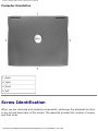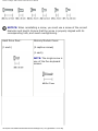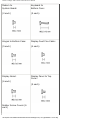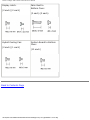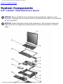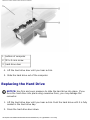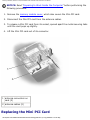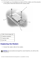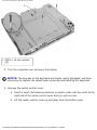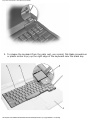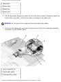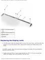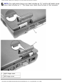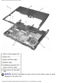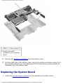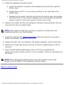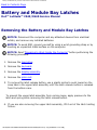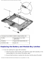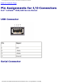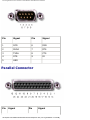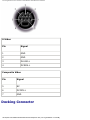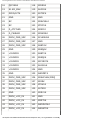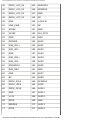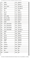
1
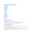
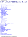
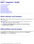
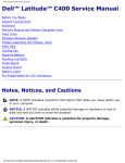
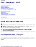
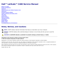
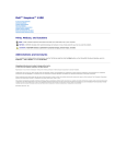
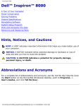
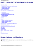
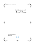
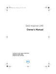
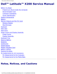
Dell Latitude C540/C640 Service Manual
Dell™ Latitude™ C540/C640 Service
Manual
Before You Begin
System Components
Hard Drive
Memory Modules, Mini PCI Card, and Modem
Keyboard
Display Assembly, Display Latch, and Hinge Covers
Palm Rest
Microprocessor Thermal Cooling Assembly
Microprocessor Module
Hybrid Cooling Fan
Reserve Battery
Flashing the BIOS
Speaker Assemblies
System Board
Battery and Module Bay Latches
Pin Assignments for I/O Connectors
Notes, Notices, and Cautions
NOTE: A NOTE indicates important information that helps you make better use
of your computer.
NOTICE: A NOTICE indicates either potential damage to hardware or loss of
data and tells you how to avoid the problem.
CAUTION: A CAUTION indicates a potential for property damage,
personal injury, or death.
file:///F|/Service%20Manuals/Dell/Latitude/c540-640/index.htm (1 of 2) [2/28/2004 7:57:39 AM]
Dell Latitude C540/C640 Service Manual
Trademarks used in this text: Dell, the DELL logo, and Latitude are trademarks of Dell Computer
Corporation.
Other trademarks and trade names may be used in this document to refer to either the entities
claiming the marks and names or their products. Dell Computer Corporation disclaims any proprietary
interest in trademarks and trade names other than its own.
April 2003 Rev. A01
file:///F|/Service%20Manuals/Dell/Latitude/c540-640/index.htm (2 of 2) [2/28/2004 7:57:39 AM]
Before You Begin: Dell Latitude C540/C640 Service Manual
Back to Contents Page
Before You Begin
Dell™ Latitude™ C540/C640 Service Manual
Preparing to Work Inside the Computer
Recommended Tools
Screw Identification
Preparing to Work Inside the Computer
CAUTION: Before working inside your computer, read the safety
instructions in your System Information Guide.
CAUTION: Only a certified service technician should perform repairs on
your computer. Damage due to servicing that is not authorized by Dell
is not covered by your warranty.
NOTICE: To avoid damaging the computer, perform the following steps before
you begin working inside the computer.
1. Ensure that the work surface is clean to prevent scratching the computer cover.
2. Save any work in progress and exit all open programs.
3. Turn off the computer and all attached devices.
NOTE: Before turning off the computer, ensure that the computer is not in a
power management mode. If you cannot shut down the computer using the
computer operating system, press and hold the power button for 4 seconds.
4. If the computer is connected (docked) to a docking device, undock it. See the
documentation that came with the docking device for instructions.
5. Disconnect the computer and any attached devices from electrical outlets.
file:///F|/Service%20Manuals/Dell/Latitude/c540-640/begin.htm (1 of 6) [2/28/2004 7:57:45 AM]
Before You Begin: Dell Latitude C540/C640 Service Manual
6. To avoid possible damage to the system board, wait 10 to 20 seconds and then
disconnect any attached devices.
7. Disconnect all other external cables from the computer.
8. Remove any installed PC Cards or plastic blanks from the PC Card slot.
9. Close the display and turn the computer upside down on a flat work surface.
NOTICE: To avoid damaging the system board, you must remove the main
battery and secondary battery (if present) before you service the computer.
10. Remove the primary battery from the battery bay and the secondary battery
from the module bay, if a secondary battery is in use.
11. Remove any installed device in the module bay.
12. To dissipate any static electricity while you work, use a wrist grounding strap or
periodically touch an unpainted metal surface.
13. Handle components and cards with care. Do not touch the components or
contacts on a card. Hold a card by it edges or by its metal mounting bracket.
Hold a component such as a microprocessor by its edges, not by its pins.
Recommended Tools
The procedures in this manual require the following tools:
●
#1 magnetized Phillips screwdriver
●
¼-inch flat-blade screwdriver
●
Small plastic scribe
●
Microprocessor extractor
●
Flash BIOS update program floppy disk or CD.
file:///F|/Service%20Manuals/Dell/Latitude/c540-640/begin.htm (2 of 6) [2/28/2004 7:57:45 AM]
Before You Begin: Dell Latitude C540/C640 Service Manual
Computer Orientation
1 back
2 right
3 front
4 left
Screw Identification
When you are removing and replacing components, photocopy the placemat as a tool
to lay out and keep track of the screws. The placemat provides the number of screws
and their sizes.
file:///F|/Service%20Manuals/Dell/Latitude/c540-640/begin.htm (3 of 6) [2/28/2004 7:57:45 AM]
Before You Begin: Dell Latitude C540/C640 Service Manual
NOTICE: When reinstalling a screw, you must use a screw of the correct
diameter and length. Ensure that the screw is properly aligned with its
corresponding hole, and avoid overtightening.
Hard Drive Door:
Memory Module Cover:
(1 each)
(2 captive screws)
(1 each)
NOTE: The single screw is
one of the five keyboard
screws.
file:///F|/Service%20Manuals/Dell/Latitude/c540-640/begin.htm (4 of 6) [2/28/2004 7:57:45 AM]
Before You Begin: Dell Latitude C540/C640 Service Manual
Modem to
System Board:
Keyboard to
Bottom Case:
(2 each)
(5 each)
Hinges to Bottom Case:
Display-Feed Flex Cable:
(5 each)
(4 each)
Display Bezel:
Display Panel to Top
Cover:
(6 each)
(5 each)
Rubber Screw Covers (6
each)
file:///F|/Service%20Manuals/Dell/Latitude/c540-640/begin.htm (5 of 6) [2/28/2004 7:57:45 AM]
Before You Begin: Dell Latitude C540/C640 Service Manual
Display Latch:
(2 each) (2 each)
Hybrid Cooling Fan:
(2 each) (1 each)
Palm Rest to
Bottom Case:
(3 each) (5 each)
System Board to Bottom
Case:
(10 each)
Back to Contents Page
file:///F|/Service%20Manuals/Dell/Latitude/c540-640/begin.htm (6 of 6) [2/28/2004 7:57:45 AM]
System Components: Dell Latitude C540/C640 Service Manual
Back to Contents Page
System Components
Dell™ Latitude™ C540/C640 Service Manual
NOTICE: Only a certified service technician should perform repairs on your
computer. Damage due to servicing that is not authorized by Dell is not covered
by your warranty.
NOTICE: Unless otherwise noted, each procedure in this document assumes
that a part can be replaced by performing the removal procedure in reverse
order.
file:///F|/Service%20Manuals/Dell/Latitude/c540-640/system.htm (1 of 2) [2/28/2004 7:57:46 AM]
System Components: Dell Latitude C540/C640 Service Manual
1 display assembly
10 bottom case
2 center control cover
11 memory module
cover
3 microprocessor thermal
cooling assembly
12 module bay device
4 hybrid cooling fan
13 main battery
5 microprocessor
14 hard drive
6 system board
15 left speaker
7 right speaker
16 palm rest
8 modem and network-adapter
connector cover
17 keyboard
9 fan guard
Back to Contents Page
file:///F|/Service%20Manuals/Dell/Latitude/c540-640/system.htm (2 of 2) [2/28/2004 7:57:46 AM]
Hard Drive: Dell Latitude C540/C640 Service Manual
Back to Contents Page
Hard Drive
Dell™ Latitude™ C540/C640 Service Manual
Removing the Hard Drive
1. Save and close any open files, exit any open programs, and then shut down the
computer.
NOTICE: Disconnect the computer and any attached devices from electrical
outlets, and remove any installed batteries.
NOTICE: The hard drive is very sensitive to shock. Handle the hard drive by its
edges (do not squeeze the top of the hard drive case), and avoid dropping it.
NOTICE: Read "Preparing to Work Inside the Computer" before performing the
following procedure.
NOTICE: To prevent data loss, turn off your computer before removing the
hard drive. Do not remove the hard drive while the computer is running, in
standby mode, or in hibernate mode.
CAUTION: If you remove the hard drive from the computer when the
drive is hot, do not touch the metal housing of the hard drive.
2. Ground yourself by touching a metal connector on the back of the computer.
3. Turn the computer over. Remove the M3 x 5-mm screw from the hard drive
door.
file:///F|/Service%20Manuals/Dell/Latitude/c540-640/hdd.htm (1 of 3) [2/28/2004 7:57:47 AM]
Hard Drive: Dell Latitude C540/C640 Service Manual
1
bottom of computer
2
M3 x 5-mm screw
3
hard drive door
4. Lift the hard drive door until you hear a click.
5. Slide the hard drive out of the computer.
Replacing the Hard Drive
NOTICE: Use firm and even pressure to slide the hard drive into place. If you
force the hard drive into place using excessive force, you may damage the
connector.
1. Lift the hard drive door until you hear a click. Push the hard drive until it is fully
seated in the hard drive bay.
2. Press the hard drive door down.
file:///F|/Service%20Manuals/Dell/Latitude/c540-640/hdd.htm (2 of 3) [2/28/2004 7:57:47 AM]
Hard Drive: Dell Latitude C540/C640 Service Manual
3. Replace the M3 x 5-mm screw in the hard drive door.
Back to Contents Page
file:///F|/Service%20Manuals/Dell/Latitude/c540-640/hdd.htm (3 of 3) [2/28/2004 7:57:47 AM]
Memory Modules, Mini PCI Card, and Modem: Dell Latitude C540/C640 Service Manual
Back to Contents Page
Memory Modules, Mini PCI Card, and
Modem
Dell™ Latitude™ C540/C640 Service Manual
Memory Modules
Mini PCI Card
Modem
Memory Modules
Removing the Memory Module Cover
NOTICE: Disconnect the computer and any attached devices from electrical
outlets, and remove any installed batteries.
NOTICE: To avoid ESD, ground yourself by using a wrist grounding strap or by
touching an unpainted metal surface on the computer.
NOTICE: Read "Preparing to Work Inside the Computer" before performing the
following procedure.
1. Turn the computer over and loosen the two captive screws from the memory
module cover.
2. Remove the M2.5 x 12-mm screw labeled "circle K" from the memory module
cover. (This screw is also one of the five keyboard screws.)
3. Place your finger under the cover at the indentation and lift and slide the cover
open.
file:///F|/Service%20Manuals/Dell/Latitude/c540-640/upgrades.htm (1 of 8) [2/28/2004 7:57:48 AM]
Memory Modules, Mini PCI Card, and Modem: Dell Latitude C540/C640 Service Manual
1 M2.5 x 12-mm screw
(1)
2 captive screws (2)
Removing the Memory Modules
NOTICE: Disconnect the computer and any attached devices from electrical
outlets, and remove any installed batteries.
NOTICE: To avoid ESD, ground yourself by using a wrist grounding strap or by
touching an unpainted metal surface on the computer.
NOTICE: Read "Preparing to Work Inside the Computer" before performing the
following procedure.
1. Remove the memory module cover.
file:///F|/Service%20Manuals/Dell/Latitude/c540-640/upgrades.htm (2 of 8) [2/28/2004 7:57:48 AM]
Memory Modules, Mini PCI Card, and Modem: Dell Latitude C540/C640 Service Manual
NOTICE: To prevent damage to the memory module connector, do not use
tools to spread the inner metal tabs that secure the memory module.
2. Use your fingertips to carefully spread apart the inner tabs on each end of the
memory module socket. The module should pop up.
1 JDIM 2 memory socket
2 JDIM 1 memory socket
3 keying tab
4 keying notch
5 inner tabs (2 per socket)
3. Lift the memory module out of its socket.
file:///F|/Service%20Manuals/Dell/Latitude/c540-640/upgrades.htm (3 of 8) [2/28/2004 7:57:48 AM]
Memory Modules, Mini PCI Card, and Modem: Dell Latitude C540/C640 Service Manual
Replacing the Memory Modules
1. If you only have one memory module, install it in the connector labeled "JDIM1"
on the system board. Install a second memory module in the connector labeled
"JDIM2."
NOTE: Memory modules are keyed, or designed to fit into their sockets, in only
one direction.
NOTICE: The memory module must be inserted at a 45-degree angle to avoid
damaging the connector.
2. Align the notch in the memory-module edge connector with the tab in the
socket.
3. Slide the edge connector of the module firmly into the socket at a
45-degree angle, and rotate the module down until it clicks into place. If you do
not feel the click, remove the module and reinstall it.
4. Replace the memory module cover and tighten the two captive screws.
Mini PCI Card
You must remove the Mini PCI card before the system board can be removed.
Removing the Mini PCI Card
NOTICE: Disconnect the computer and any attached devices from electrical
outlets, and remove any installed batteries.
NOTICE: To avoid ESD, ground yourself by using a wrist grounding strap or by
touching an unpainted metal surface on the computer.
file:///F|/Service%20Manuals/Dell/Latitude/c540-640/upgrades.htm (4 of 8) [2/28/2004 7:57:48 AM]
Memory Modules, Mini PCI Card, and Modem: Dell Latitude C540/C640 Service Manual
NOTICE: Read "Preparing to Work Inside the Computer" before performing the
following procedure.
1. Remove the memory module cover, which also covers the Mini-PCI card.
2. Disconnect the Mini PCI card from the antenna cables.
3. To release a Mini PCI card from its socket, spread apart the metal securing tabs
until the card pops up slightly.
4. Lift the Mini PCI card out of its connector.
1 antenna connectors on
card (2)
2 antenna cables (2)
Replacing the Mini PCI Card
file:///F|/Service%20Manuals/Dell/Latitude/c540-640/upgrades.htm (5 of 8) [2/28/2004 7:57:48 AM]
Memory Modules, Mini PCI Card, and Modem: Dell Latitude C540/C640 Service Manual
1. Align the Mini PCI card with the socket at a 45-degree angle, and press the Mini
PCI card into the socket.
NOTICE: The connectors are keyed for correct insertion; do not force the
connections.
2. Pivot the Mini PCI card down until it snaps into the inner tabs of the socket.
3. Attach the antenna cables to the Mini PCI card.
4. Replace the memory module cover and tighten the two captive screws.
Modem
Removing the Modem
NOTICE: Disconnect the computer and any attached devices from electrical
outlets, and remove any installed batteries.
NOTICE: To avoid ESD, ground yourself by using a wrist grounding strap or by
touching an unpainted metal surface on the computer.
NOTICE: Read "Preparing to Work Inside the Computer" before performing the
following procedure.
1. Turn the computer over, and remove the memory module cover, which also
covers the modem.
2. Remove the two M2 x 3-mm screws that secure the modem to the system
board.
NOTICE: Do not pull on the modem cable. Pull from the modem connector to
disconnect the cable.
file:///F|/Service%20Manuals/Dell/Latitude/c540-640/upgrades.htm (6 of 8) [2/28/2004 7:57:48 AM]
Memory Modules, Mini PCI Card, and Modem: Dell Latitude C540/C640 Service Manual
3. Pull straight up on the attached pull-tab to lift the modem out of its connector
on the system board and disconnect the modem cable.
1 M2 x 3-mm screws (2)
2 modem connector
3 modem cable
4 pull-tab
Replacing the Modem
1. Connect the modem cable to the modem.
NOTICE: The connectors are keyed for correct insertion; do not force the
connections.
file:///F|/Service%20Manuals/Dell/Latitude/c540-640/upgrades.htm (7 of 8) [2/28/2004 7:57:48 AM]
Memory Modules, Mini PCI Card, and Modem: Dell Latitude C540/C640 Service Manual
2. Align the modem with the screw holes on the system board and press down on
the pull-tab to seat the modem in the connector.
NOTICE: Pressing down on the modem somewhere other than on the pull-tab
can break the modem.
3. Install the two M2 x 3-mm screws that secure the modem to the system board.
4. Replace the memory module cover and tighten the two captive screws.
Back to Contents Page
file:///F|/Service%20Manuals/Dell/Latitude/c540-640/upgrades.htm (8 of 8) [2/28/2004 7:57:48 AM]
Keyboard: Dell Latitude C540/C640 Service Manual
Back to Contents Page
Keyboard
Dell™ Latitude™ C540/C640 Service Manual
Removing the Keyboard
NOTICE: Disconnect the computer and any attached devices from electrical
outlets, and remove any installed batteries.
NOTICE: To avoid ESD, ground yourself by using a wrist grounding strap or by
touching an unpainted metal surface on the computer.
NOTICE: Read "Preparing to Work Inside the Computer" before performing the
following procedure.
1. Remove the hard drive.
2. Turn the computer over, and remove the five M2.5 x 12-mm screws labeled
"circle K."
file:///F|/Service%20Manuals/Dell/Latitude/c540-640/keyboard.htm (1 of 6) [2/28/2004 7:57:48 AM]
Keyboard: Dell Latitude C540/C640 Service Manual
1 M2.5 x 12-mm screws
(5)
3. Turn the computer over and open the display.
NOTICE: The keycaps on the keyboard are fragile, easily dislodged, and timeconsuming to replace. Be careful when removing and handling the keyboard.
4. Remove the center control cover:
a. Insert a small, flat-blade screwdriver or plastic scribe into the notch at the
right end of the center control cover and pry up the cover.
b. Lift the center control cover up and away from the bottom case.
file:///F|/Service%20Manuals/Dell/Latitude/c540-640/keyboard.htm (2 of 6) [2/28/2004 7:57:48 AM]
Keyboard: Dell Latitude C540/C640 Service Manual
5. To release the keyboard from the palm rest, use a small, flat-blade screwdriver
or plastic scribe to pry up the right edge of the keyboard near the blank key.
file:///F|/Service%20Manuals/Dell/Latitude/c540-640/keyboard.htm (3 of 6) [2/28/2004 7:57:48 AM]
Keyboard: Dell Latitude C540/C640 Service Manual
1 keyboard
2 track stick
3 blank key
4 palm rest
6. Lift the keyboard straight up about an inch and then rotate it forward toward the
front of the computer, until the key face is resting on the palm rest.
NOTICE: Do not pull on the keyboard flex and track stick cables.
7. Pull up on the keyboard connector to disconnect it from the keyboard interface
connector on the system board.
1 boss supports (5)
2 track stick cable
3 keyboard flex cable
file:///F|/Service%20Manuals/Dell/Latitude/c540-640/keyboard.htm (4 of 6) [2/28/2004 7:57:48 AM]
Keyboard: Dell Latitude C540/C640 Service Manual
4 keyboard interface
connector
5 orientation label
8. Remove the keyboard from the bottom case.
Replacing the Keyboard
1. Place the keyboard on the palm rest at the front of the computer with the keys
face down and the connector toward the back of the computer.
NOTICE: To avoid damage to the connector pins, press the keyboard connector
evenly into the interface connector on the system board, and do not reverse the
keyboard connector.
2. Connect the keyboard connector to the interface connector on the system board.
The keyboard connector may have a label showing the correct orientation of the
keyboard connector (relative to the display) in the system-board interface
connector.
3. Carefully turn the keyboard over. Align the keyboard boss supports, fit the left
side of the keyboard into place, and then snap the right side of the keyboard
into place.
NOTICE: Position the keyboard flex and track stick cables so that they are not
pinched when you replace the keyboard in the bottom case.
4. Check that the keyboard is correctly installed. The keys should be flush with the
left and right surfaces of the palm rest.
5. Replace the center control cover, close the display assembly, and then turn the
computer over.
6. Reinstall the five M2.5 x 12-mm screws in the holes labeled "circle K."
file:///F|/Service%20Manuals/Dell/Latitude/c540-640/keyboard.htm (5 of 6) [2/28/2004 7:57:48 AM]
Keyboard: Dell Latitude C540/C640 Service Manual
Back to Contents Page
file:///F|/Service%20Manuals/Dell/Latitude/c540-640/keyboard.htm (6 of 6) [2/28/2004 7:57:48 AM]
Display Assembly, Display Latch, and Hinge Covers: Dell Latitude C540/C640 Service Manual
Back to Contents Page
Display Assembly, Display Latch, and
Hinge Covers
Dell™ Latitude™ C540/C640 Service Manual
Display Assembly
Display Latch
Hinge Covers
Display Assembly
NOTICE: You must remove the display assembly before you remove the palm rest.
NOTICE: Disconnect the computer and any attached devices from electrical outlets,
and remove any installed batteries.
NOTICE: To avoid ESD, ground yourself by using a wrist grounding strap or by
touching an unpainted metal surface on the computer.
NOTICE: Read "Preparing to Work Inside the Computer" before performing the
following procedureDisplay Assembly
1. Remove the hard drive.
2. Remove the center control cover.
3. Remove the keyboard.
4. Close the display.
5. From the back of the computer, remove the five M2.5 x 5-mm screws labeled "circle
D."
6. Open the display assembly approximately 180 degrees and support the display
assembly so that it does not open past this position.
7. Remove the two M2 x 3-mm screws on the EMI shield bracket, which is attached to
the display-feed flex cable.
file:///F|/Service%20Manuals/Dell/Latitude/c540-640/display.htm (1 of 12) [2/28/2004 7:57:51 AM]
Display Assembly, Display Latch, and Hinge Covers: Dell Latitude C540/C640 Service Manual
1 M2 x 3-mm screws (2)
2 top cover
3 center control cover
4 M2.5 x 5-mm screws (5)
5 bottom case
6 display-feed flex cable
7 EMI shield bracket
8. Remove the two M2 x 3-mm screws that secure the display-feed flex cable to the
system board.
file:///F|/Service%20Manuals/Dell/Latitude/c540-640/display.htm (2 of 12) [2/28/2004 7:57:51 AM]
Display Assembly, Display Latch, and Hinge Covers: Dell Latitude C540/C640 Service Manual
NOTICE: When reconnecting the display-feed flex cable connector to the system
board, push down on the top left and right ends of the connector. Pressing on the
center of the connector may damage resistors and compromise EMI protection in
the computer.
1 M2 x 3-mm screws (2)
2 pull-tab
3 display-feed cable
connector
4 interface connector
9. Pull up on the pull-tab that is attached to the display-feed flex cable connector to
file:///F|/Service%20Manuals/Dell/Latitude/c540-640/display.htm (3 of 12) [2/28/2004 7:57:51 AM]
Display Assembly, Display Latch, and Hinge Covers: Dell Latitude C540/C640 Service Manual
remove it from the interface connector on the system board.
10. Pivot the display assembly up to a 90-degree angle and lift it out of the bottom
case.
file:///F|/Service%20Manuals/Dell/Latitude/c540-640/display.htm (4 of 12) [2/28/2004 7:57:51 AM]
Display Assembly, Display Latch, and Hinge Covers: Dell Latitude C540/C640 Service Manual
1 rubber screw covers
(6)
5 M2 x 4-mm screws (5)
2 M2.5 x 5-mm screws
(6)
6 display-feed flex cable
3 display bezel
7 flex-cable retention bracket
4 top cover
8 display panel
Removing the Display Bezel
NOTICE: Disconnect the computer and any attached devices from electrical outlets,
and remove any installed batteries.
NOTICE: To avoid ESD, ground yourself by using a wrist grounding strap or by
touching an unpainted metal surface on the computer.
NOTICE: Read "Preparing to Work Inside the Computer" before performing the
following procedure.
1. Remove the hard drive.
2. Remove the display assembly.
3. Use a plastic scribe to pry the six rubber screw covers out of the screw holes located
on the front of the bezel.
4. Remove the six M2.5 x 5-mm screws located on the front of the bezel.
NOTICE: Carefully separate the bezel from the top cover to avoid damage to the
bezel.
5. Starting at the bottom of the display panel (by the Dell™ logo), use your fingers to
separate the bezel from the top cover by lifting the inside of the bezel while pushing
in on the outside.
Removing the Display Panel
NOTICE: Disconnect the computer and any attached devices from electrical outlets,
and remove any installed batteries.
file:///F|/Service%20Manuals/Dell/Latitude/c540-640/display.htm (5 of 12) [2/28/2004 7:57:51 AM]
Display Assembly, Display Latch, and Hinge Covers: Dell Latitude C540/C640 Service Manual
NOTICE: To avoid ESD, ground yourself by using a wrist grounding strap or by
touching an unpainted metal surface on the computer.
NOTICE: Read "Preparing to Work Inside the Computer" before performing the
following procedure.
1. Remove the hard drive.
2. Remove the display assembly.
3. Remove the display bezel.
4. Remove the hinge covers.
5. Remove the two M2 x 4-mm screws on the left side of the display panel and the two
M2 x 4-mm screws on the right side of the display panel.
NOTE: If you have a Hitachi display panel, remove the two M2 x 4-mm screws from
the center of the left side of the display panel.
6. Remove the M2 x 4-mm screw that secures the display-feed flex cable through the
black plastic flex-cable retention bracket.
7. Lift from the top and rotate the display panel out of the top cover.
8. Disconnect the bottom flex cable connector from the inverter connector by pulling
straight up on the attached pull-tab.
file:///F|/Service%20Manuals/Dell/Latitude/c540-640/display.htm (6 of 12) [2/28/2004 7:57:51 AM]
Display Assembly, Display Latch, and Hinge Covers: Dell Latitude C540/C640 Service Manual
1 display panel connector
2 top flex cable connector
3 pull-tab
4 bottom flex cable
connector
5 inverter connector
9. Remove the tape that secures the display panel connector and the tape that secures
the middle of the display-feed flex cable to the display panel.
10. Pull the top flex cable connector down and away to remove it from the display panel
connector.
Replacing the Display Panel
file:///F|/Service%20Manuals/Dell/Latitude/c540-640/display.htm (7 of 12) [2/28/2004 7:57:51 AM]
Display Assembly, Display Latch, and Hinge Covers: Dell Latitude C540/C640 Service Manual
1. Reconnect the top flex cable connector to the display panel connector.
2. Reconnect the bottom flex cable connector to the inverter connector.
3. Replace the tape that secures the display panel connector and the tape that secures
the middle of the display-feed flex cable to the display panel.
4. Place the bottom edge of the display panel in the bottom of the top cover and lift
the top of the panel with your hand.
5. Lay the display panel in the top cover.
6. Reinstall the five M2 x 4-mm screws that secure the display panel to the top cover.
Display Latch
NOTICE: Disconnect the computer and any attached devices from electrical outlets,
and remove any installed batteries.
NOTICE: To avoid ESD, ground yourself by using a wrist grounding strap or by
touching an unpainted metal surface on the computer.
Removing the Display Latch
1. Remove the hard drive.
2. Remove the display assembly.
3. Remove the display bezel.
4. Remove the two M2.5 x 5-mm screws and the two M1.7 x 3.5-mm screws that
secure the display latch and bracket to the top cover.
5. Lift the display latch and bracket out of the top cover.
XGA Panel Shown
file:///F|/Service%20Manuals/Dell/Latitude/c540-640/display.htm (8 of 12) [2/28/2004 7:57:51 AM]
Display Assembly, Display Latch, and Hinge Covers: Dell Latitude C540/C640 Service Manual
1 M1.7 x 3.5-mm screws
(2)
2 M2.5 x 5-mm screws (2)
3 display latch
4 bracket
Replacing the Display Latch
1. On XGA panels, place the display latch on top of its screw holes, and then place the
bracket on top of the display latch, aligning the bracket and display latch screw
holes.
On SXGA+ panels, align the screw holes and place the display latch and attached
bracket in the top cover.
2. Replace the two M2.5 x 5-mm screws and the two M1.7 x 3.5-mm screws that
secure the display latch and bracket to the top cover.
file:///F|/Service%20Manuals/Dell/Latitude/c540-640/display.htm (9 of 12) [2/28/2004 7:57:51 AM]
Display Assembly, Display Latch, and Hinge Covers: Dell Latitude C540/C640 Service Manual
Hinge Covers
Removing the Hinge Covers
1. Remove the display assembly.
2. Rotate the hinges forward at an angle of approximately 90 degrees to the front of
the display assembly.
3. To remove the hinge covers, slide them off the hinges.
Replacing the Hinge Covers
1. Attach the display assembly to the bottom case.
2. Close the display.
3. Snap the hinge covers in place over the hinges.
file:///F|/Service%20Manuals/Dell/Latitude/c540-640/display.htm (10 of 12) [2/28/2004 7:57:51 AM]
Display Assembly, Display Latch, and Hinge Covers: Dell Latitude C540/C640 Service Manual
NOTE: The right plastic hinge cover label includes an "R," and the left plastic hinge
cover label includes an "L." The hinge cover labels face the back of the computer.
1
right hinge cover
2
left hinge cover
file:///F|/Service%20Manuals/Dell/Latitude/c540-640/display.htm (11 of 12) [2/28/2004 7:57:51 AM]
Display Assembly, Display Latch, and Hinge Covers: Dell Latitude C540/C640 Service Manual
Back to Contents Page
file:///F|/Service%20Manuals/Dell/Latitude/c540-640/display.htm (12 of 12) [2/28/2004 7:57:51 AM]
Palm Rest: Dell Latitude C540/C640 Service Manual
Back to Contents Page
Palm Rest
Dell™ Latitude™ C540/C640 Service Manual
Removing the Palm Rest
NOTICE: Disconnect the computer and any attached devices from electrical
outlets, and remove any installed batteries.
NOTICE: To avoid ESD, ground yourself by using a wrist grounding strap or by
touching an unpainted metal surface on the computer.
NOTICE: Read "Preparing to Work Inside the Computer" before performing the
following procedure.
1. Remove the hard drive.
2. Remove the keyboard.
NOTICE: You must remove the display assembly before you remove the palm
rest; the display hinges pass through the back of the palm rest.
3. Remove the display assembly and hinge covers.
4. Turn the computer over and remove the three M2.5 x 12-mm screws labeled
"circle P."
file:///F|/Service%20Manuals/Dell/Latitude/c540-640/palmrest.htm (1 of 4) [2/28/2004 7:57:52 AM]
Palm Rest: Dell Latitude C540/C640 Service Manual
1 M2.5 x 12-mm screws
(3)
2 M2 x 3-mm screws (2)
3 hard-drive bay door
5. Remove the two M2 x 3-mm screws that are located in the hard-drive bay door
labeled "circle P."
6. Turn the computer over, and remove the three M2 x 3-mm screws that secure
the palm rest to the bottom case:
a. Remove the two M2 x 3-mm screws that are located on the back edge of
the bottom case, underneath the display assembly.
b. Remove the M2 x 3-mm screw located near the right side of the bottom
case, next to the microprocessor thermal cooling assembly and opposite
the S-video TV-out connector.
7. Pull up on the pull-tab that is attached to the palm-rest flex cable connector to
remove it from the interface connector on the system board.
file:///F|/Service%20Manuals/Dell/Latitude/c540-640/palmrest.htm (2 of 4) [2/28/2004 7:57:52 AM]
Palm Rest: Dell Latitude C540/C640 Service Manual
1 M2 x 3-mm screws (3)
2 palm rest
3 palm-rest flex cable
4 bottom case
5 interface connector for
palm-rest flex cable
6 back center of the palm
rest
NOTICE: Carefully separate the palm rest from the bottom case to avoid
damage to the palm rest.
file:///F|/Service%20Manuals/Dell/Latitude/c540-640/palmrest.htm (3 of 4) [2/28/2004 7:57:52 AM]
Palm Rest: Dell Latitude C540/C640 Service Manual
8. Starting at the back center of the palm rest, use your fingers to separate the
palm rest from the bottom case by lifting the inside of the palm rest while
pushing in on the outside.
Back to Contents Page
file:///F|/Service%20Manuals/Dell/Latitude/c540-640/palmrest.htm (4 of 4) [2/28/2004 7:57:52 AM]
Microprocessor Thermal Cooling Assembly: Dell Latitude C540/C640 Service Manual
Back to Contents Page
Microprocessor Thermal Cooling
Assembly
Dell™ Latitude™ C540/C640 Service Manual
Removing the Microprocessor Thermal Cooling
Assembly
NOTICE: Disconnect the computer and any attached devices from electrical
outlets, and remove any installed batteries.
NOTICE: To avoid ESD, ground yourself by using a wrist grounding strap or by
touching an unpainted metal surface on the computer.
NOTICE: Read "Preparing to Work Inside the Computer" before performing the
following procedure.
1. Remove the hard drive.
2. Remove the keyboard.
3. Loosen the four captive screws that secure the microprocessor thermal cooling
assembly.
file:///F|/Service%20Manuals/Dell/Latitude/c540-640/thermal.htm (1 of 3) [2/28/2004 7:57:52 AM]
Microprocessor Thermal Cooling Assembly: Dell Latitude C540/C640 Service Manual
1 microprocessor thermal
cooling assembly
2 captive screws (4)
3 right side of thermal
cooling assembly
4 recess in EMI shield
(prying location)
4. Insert a screwdriver into the recess in the EMI shield under the front left corner
of the thermal cooling assembly, and pry the assembly up and out of the system
board.
Replacing the Microprocessor Thermal Cooling
Assembly
file:///F|/Service%20Manuals/Dell/Latitude/c540-640/thermal.htm (2 of 3) [2/28/2004 7:57:52 AM]
Microprocessor Thermal Cooling Assembly: Dell Latitude C540/C640 Service Manual
NOTICE: To ensure proper thermal operation, always install a new, compatible
thermal cooling assembly along with a new microprocessor.
1. Place the right side of the microprocessor thermal cooling assembly under the
palm rest and lower the assembly onto the system board.
2. Tighten the four captive screws, labeled 1 through 4, in consecutive order.
Back to Contents Page
file:///F|/Service%20Manuals/Dell/Latitude/c540-640/thermal.htm (3 of 3) [2/28/2004 7:57:52 AM]
Microprocessor Module: Dell Latitude C540/C640 Service Manual
Back to Contents Page
Microprocessor Module
Dell™ Latitude™ C540/C640 Service Manual
Removing the Microprocessor Module
NOTICE: Disconnect the computer and any attached devices from electrical
outlets, and remove any installed batteries.
NOTICE: To avoid ESD, ground yourself by using a wrist grounding strap or by
touching an unpainted metal surface on the computer.
NOTICE: Read "Preparing to Work Inside the Computer" before performing the
following procedure.
NOTICE: To ensure proper thermal operation, always install a new, compatible
thermal cooling assembly along with a new microprocessor.
NOTICE: Do not touch the processor die. To ensure proper seating of the
microprocessor in the socket, press down near the edges of the microprocessor
module (on the substrate surrounding the die) while turning the cam screw.
NOTICE: To avoid damage to the microprocessor, hold the screwdriver so that
it is perpendicular to the microprocessor when turning the cam screw.
file:///F|/Service%20Manuals/Dell/Latitude/c540-640/cpu.htm (1 of 4) [2/28/2004 7:57:53 AM]
Microprocessor Module: Dell Latitude C540/C640 Service Manual
1 screwdriver
(perpendicular to
microprocessor)
2 pin-1 corner
3 processor die (do not
touch)
4 ZIF socket
5 ZIF-socket cam screw
1. Remove the hard drive.
2. Remove the keyboard.
NOTICE: To ensure maximum cooling for the microprocessor, do not touch the
heat transfer areas on the microprocessor thermal cooling assembly. The oils in
your skin reduce the heat transfer capability of the thermal pads.
file:///F|/Service%20Manuals/Dell/Latitude/c540-640/cpu.htm (2 of 4) [2/28/2004 7:57:53 AM]
Microprocessor Module: Dell Latitude C540/C640 Service Manual
3. Remove the microprocessor thermal cooling assembly.
NOTICE: When removing the microprocessor module, pull the module straight
up. Be careful not to bend the pins on the microprocessor module.
4. To loosen the ZIF socket, use a small, flat-blade screwdriver and rotate the ZIFsocket cam screw counter-clockwise until it reaches the cam stop.
The ZIF-socket cam screw secures the microprocessor to the system board. Take
note of the arrow on the ZIF-socket cam screw.
5. Use a microprocessor extraction tool to remove the microprocessor module.
Replacing the Microprocessor Module
NOTICE: Ensure that the cam lock is in the fully open position before seating
the microprocessor module. Seating the microprocessor module properly in the
ZIF socket does not require force.
NOTICE: A microprocessor module that is not properly seated can result in an
intermittent connection, or permanent damage to the microprocessor and ZIF
socket.
1. Align the pin-1 corner of the microprocessor module with the pin-1 corner of the
ZIF socket, and insert the microprocessor module.
NOTE: The pin-1 corner of the microprocessor module has a triangle that aligns
with a triangle (or missing hole) on the pin-1 corner of the ZIF socket.
NOTICE: You must position the microprocessor module correctly in the ZIF
socket to avoid permanent damage to the module and the socket.
When the microprocessor module is correctly seated, all four corners are aligned
at the same height. If one or more corners of the module are higher than the
others, the module is not seated correctly.
file:///F|/Service%20Manuals/Dell/Latitude/c540-640/cpu.htm (3 of 4) [2/28/2004 7:57:53 AM]
Microprocessor Module: Dell Latitude C540/C640 Service Manual
NOTICE: Do not touch the processor dienear the edges of the microprocessor
module (on the substrate surrounding the die) while turning the cam screw.
2. Press down on the edges of the microprocessor module and tighten the ZIF
socket by turning the cam screw clockwise.
3. Install a new microprocessor thermal cooling assembly.
NOTICE: To ensure proper thermal operation, always install a new, compatible
thermal cooling assembly along with a new microprocessor.
4. Update the BIOS using the flash BIOS update floppy disk or CD. For instructions
on how to flash the BIOS, see "Flashing the BIOS."
Back to Contents Page
file:///F|/Service%20Manuals/Dell/Latitude/c540-640/cpu.htm (4 of 4) [2/28/2004 7:57:53 AM]
Hybrid Cooling Fan: Dell Latitude C540/C640 Service Manual
Back to Contents Page
Hybrid Cooling Fan
Dell™ Latitude™ C540/C640 Service Manual
Removing the Hybrid Cooling Fan
NOTICE: Disconnect the computer and any attached devices from electrical
outlets, and remove any installed batteries.
NOTICE: To avoid ESD, ground yourself by using a wrist grounding strap or by
touching an unpainted metal surface on the computer.
NOTICE: Read "Preparing to Work Inside the Computer" before performing the
following procedure.
1. Remove the hard drive.
2. Remove the keyboard.
3. Remove the display assembly.
4. Remove the palm rest.
5. Remove the microprocessor thermal cooling assembly.
6. Remove the two M2.5 x 5-mm screws and one M2 x 3-mm screw that secure
the hybrid cooling fan to the system board.
file:///F|/Service%20Manuals/Dell/Latitude/c540-640/fan.htm (1 of 3) [2/28/2004 7:57:54 AM]
Hybrid Cooling Fan: Dell Latitude C540/C640 Service Manual
1 system-board interface
connector
5 M2 x 3-mm screw
(1)
2 fan power cable
6 M2.5 x 5-mm screws
(2)
3 spring fingers
7 hybrid cooling fan
4 keyboard screw hole
7. Disconnect the fan power cable from the system-board interface connector and
remove the hybrid cooling fan.
NOTE: The fan power cable is long, and can be pulled out from under the EMI
shield to provide access to the connector.
NOTICE: Do not block the keyboard screw hole when reinstalling the fan. Route
the fan power cable under the spring fingers and behind the keyboard screw
hole to prevent damage to the fan power cable.
file:///F|/Service%20Manuals/Dell/Latitude/c540-640/fan.htm (2 of 3) [2/28/2004 7:57:54 AM]
Hybrid Cooling Fan: Dell Latitude C540/C640 Service Manual
Back to Contents Page
file:///F|/Service%20Manuals/Dell/Latitude/c540-640/fan.htm (3 of 3) [2/28/2004 7:57:54 AM]
Reserve Battery: Dell Latitude C540/C640 Service Manual
Back to Contents Page
Reserve Battery
Dell™ Latitude™ C540/C640 Service Manual
Removing the Reserve Battery
NOTICE: The reserve battery provides power to the computer's RTC and
NVRAM when the computer is turned off. Removing the battery causes the
computer to lose the date and time information as well as all user-specified
parameters in the BIOS. If possible, copy the information before you remove
the reserve battery.
NOTICE: Disconnect the computer and any attached devices from electrical
outlets, and remove any installed batteries.
NOTICE: To avoid ESD, ground yourself by using a wrist grounding strap or by
touching an unpainted metal surface on the computer.
NOTICE: Read "Preparing to Work Inside the Computer" before performing the
following procedure.
1. Remove the hard drive.
2. Remove the keyboard.
3. Disconnect the reserve battery cable from the reserve battery connector on the
system board.
4. Pry the reserve battery free from the EMI shield. The reserve battery is attached
to the EMI shield with a piece of adhesive tape.
5. Remove any remnants of the adhesive tape from the EMI shield.
file:///F|/Service%20Manuals/Dell/Latitude/c540-640/rsrvbatt.htm (1 of 3) [2/28/2004 7:57:54 AM]
Reserve Battery: Dell Latitude C540/C640 Service Manual
1 reserve battery
2 reserve battery tray
3 reserve battery cable
4 reserve battery
connector on system
board
5 speaker cables
6 opening for reserve
battery cable
Replacing the Reserve Battery
1. Connect the reserve battery cable to the reserve battery connector on the
file:///F|/Service%20Manuals/Dell/Latitude/c540-640/rsrvbatt.htm (2 of 3) [2/28/2004 7:57:54 AM]
Reserve Battery: Dell Latitude C540/C640 Service Manual
system board and then route the battery cable through the opening in the EMI
shield to the battery tray.
2. Remove the backing from the adhesive on the bottom of the reserve battery,
and press the battery into place in the battery tray.
3. Update the BIOS using a flash BIOS update floppy disk or CD. For instructions
on how to flash the BIOS, see "Flashing the BIOS."
Back to Contents Page
file:///F|/Service%20Manuals/Dell/Latitude/c540-640/rsrvbatt.htm (3 of 3) [2/28/2004 7:57:54 AM]
Flashing the BIOS: Dell Latitude C540/C640 Service Manual
Back to Contents Page
Flashing the BIOS
Dell™ Latitude™ C540/C640 Service Manual
To update the basic input/output system (BIOS):
1. Ensure that the AC adapter is plugged in and that the main battery is installed
properly.
2. Turn on the computer and press
to enter the system setup program.
3. Reset the boot sequence to boot first from the floppy drive or the CD drive
(depending on whether your flash BIOS update is supplied on floppy disk or CD).
4. Insert the flash BIOS update floppy disk or CD, and reboot the computer.
The computer updates the BIOS and then automatically reboots.
to enter the system setup program, and reset the boot
5. Immediately press
sequence to the normal setting. Then exit the system setup program.
6. Remove the flash BIOS update floppy disk or CD.
Back to Contents Page
file:///F|/Service%20Manuals/Dell/Latitude/c540-640/bios.htm [2/28/2004 7:57:55 AM]
Speaker Assemblies: Dell Latitude C540/C640 Service Manual
Back to Contents Page
Speaker Assemblies
Dell™ Latitude™ C540/C640 Service Manual
Removing the Speaker Assemblies
NOTICE: Disconnect the computer and any attached devices from electrical
outlets, and remove any installed batteries.
NOTICE: To avoid ESD, ground yourself by using a wrist grounding strap or by
touching an unpainted metal surface on the computer.
NOTICE: Read "Preparing to Work Inside the Computer" before performing the
following procedure.
The speakers are located on the front left and right sides of the bottom case. As you
remove the speakers, take note of the speaker assembly orientations and the antenna
wire routing under the routing clips.
file:///F|/Service%20Manuals/Dell/Latitude/c540-640/speakers.htm (1 of 5) [2/28/2004 7:57:56 AM]
Speaker Assemblies: Dell Latitude C540/C640 Service Manual
1 right speaker
2 palm-rest screw posts
(2)
3 bottom case holders (2)
4 left speaker
file:///F|/Service%20Manuals/Dell/Latitude/c540-640/speakers.htm (2 of 5) [2/28/2004 7:57:56 AM]
Speaker Assemblies: Dell Latitude C540/C640 Service Manual
file:///F|/Service%20Manuals/Dell/Latitude/c540-640/speakers.htm (3 of 5) [2/28/2004 7:57:56 AM]
Speaker Assemblies: Dell Latitude C540/C640 Service Manual
1 antenna cable
7
antenna cable
2 speaker interface cable
8
right speaker holder
3 in-line connector
9
mounting ring
4 left speaker
10 right speaker
5 mounting ring
11 speaker interface cable
6 left speaker holder
1. Remove the hard drive.
2. Remove the keyboard.
3. Remove the display assembly.
4. Remove the palm rest.
5. Disconnect the speaker interface cables. (Do not attempt to disconnect the
antenna cables.)
NOTICE: Do not pull the antenna wire when removing the speaker.
NOTICE: Handle the speaker assemblies and speakers carefully to avoid
damaging the speaker cones.
6. Remove the speaker assemblies by pulling them straight out of the bottom case.
7. Remove the speakers from the holders by sliding the speakers out of the bottom
of the holders.
NOTE: The left speaker has an in-line connector; the left antenna cable is longer
than the right antenna cable.
Replacing the Speaker Assemblies
For each speaker:
1. Slide the new speaker into its holder so that the speaker will face outward
file:///F|/Service%20Manuals/Dell/Latitude/c540-640/speakers.htm (4 of 5) [2/28/2004 7:57:56 AM]
Speaker Assemblies: Dell Latitude C540/C640 Service Manual
(toward the speaker grill on the side of the computer) when the speaker
assembly is installed.
2. Place the mounting ring over the front palm-rest screw post.
3. Slide the speaker assembly down into the bottom case.
NOTICE: Ensure that the speaker wires are routed securely under their
mounting clips.
Back to Contents Page
file:///F|/Service%20Manuals/Dell/Latitude/c540-640/speakers.htm (5 of 5) [2/28/2004 7:57:56 AM]
System Board: Dell Latitude C540/C640 Service Manual
Back to Contents Page
System Board
Dell™ Latitude™ C540/C640 Service Manual
Removing the System Board
The system board's BIOS chip contains the service tag sequence, which is also visible
on a bar code label on the bottom of the computer. The replacement kit for the
system board includes a CD that provides a utility for transferring the service tag
sequence to the replacement system board.
NOTICE: Disconnect the computer and any attached devices from electrical
outlets, and remove any installed batteries.
NOTICE: To avoid ESD, ground yourself by using a wrist grounding strap or by
touching an unpainted metal surface on the computer.
NOTICE: Read "Preparing to Work Inside the Computer" before performing the
following procedure.
1. Remove the hard drive.
2. Remove the keyboard.
3. Remove the display assembly.
4. Remove the palm rest.
5. Remove the microprocessor thermal cooling assembly.
6. Remove the microprocessor module.
7. Remove the modem, memory modules, and Mini PCI card.
8. From the bottom of the computer, remove the six M2.5 x 5-mm screws labeled
"circle B" that secure the system board to the bottom case.
9. Remove the three M2.5 x 5-mm screws labeled "circle B" that secure the fan
guard to the bottom case.
file:///F|/Service%20Manuals/Dell/Latitude/c540-640/sysboard.htm (1 of 4) [2/28/2004 7:57:56 AM]
System Board: Dell Latitude C540/C640 Service Manual
1 fan guard
2 M2.5 x 5-mm screws (9)
10. Turn the computer over and remove the M2.5 x 5-mm screw, which is labeled
"circle B" with an arrow on the front center of the system board by the battery
connector.
file:///F|/Service%20Manuals/Dell/Latitude/c540-640/sysboard.htm (2 of 4) [2/28/2004 7:57:56 AM]
System Board: Dell Latitude C540/C640 Service Manual
1 M2.5 x. 5-mm screw (1)
2 audio connector
locations; pull outward
here
11. Remove the speaker assemblies from the bottom case.
12. Pull the right side of the bottom case, next to the audio connectors, away from
the system board as you simultaneously lift the front of the system board out
and away from the bottom case.
Replacing the System Board
1. Install the microprocessor module on the replacement system board.
file:///F|/Service%20Manuals/Dell/Latitude/c540-640/sysboard.htm (3 of 4) [2/28/2004 7:57:56 AM]
System Board: Dell Latitude C540/C640 Service Manual
2. Install the replacement system board:
a. Insert the external microphone and headphone connectors through the
bottom case.
b. Replace the six M2.5 x 5-mm screws, starting on the right side of the
bottom case.
c. Replace the fan guard, inserting the tab into the bottom case, and replace
the three M2.5 x 5-mm screws. Replacing the screw opposite the tab first
makes it easier to insert and replace the other two screws.
3. Replace the modem and the microprocessor thermal cooling assembly that you
removed from the old system board.
NOTE: Route cables so that they will not be crimped or pinched when the
complete assembly is put back together.
4. Install the right and left speaker assemblies that came with the new system
board in the bottom case.
5. Replace the palm rest, the keyboard, the display assembly, and the hard drive.
6. Replace the module bay devices and any PC Cards or plastic blanks in the PC
Card slot.
7. Insert the flash BIOS update floppy disk or CD that accompanied the
replacement system board, and turn on the computer. Follow the instructions on
the screen.
NOTE: After replacing the system board, enter the computer service tag
sequence into the BIOS of the replacement system board.
Back to Contents Page
file:///F|/Service%20Manuals/Dell/Latitude/c540-640/sysboard.htm (4 of 4) [2/28/2004 7:57:56 AM]
Battery and Module Bay Latches: Dell Latitude C540/C640 Service Manual
Back to Contents Page
Battery and Module Bay Latches
Dell™ Latitude™ C540/C640 Service Manual
Removing the Battery and Module Bay Latches
NOTICE: Disconnect the computer and any attached devices from electrical
outlets, and remove any installed batteries.
NOTICE: To avoid ESD, ground yourself by using a wrist grounding strap or by
touching an unpainted metal surface on the computer.
NOTICE: Read "Preparing to Work Inside the Computer" before performing the
following procedure.
1. Remove the hard drive.
2. Remove the keyboard.
3. Remove the display assembly.
4. Remove the palm rest.
5. To remove the latch release button, use a plastic scribe to push inward on the
snap tabs in the upper latch assembly until the latch release button is released
from the bottom case.
To prevent the upper latch assembly from coming loose, apply pressure to the
latch and spring while removing the latch release button.
6. If you are also removing the upper latch assembly, lift it out of the latch holding
fixture.
file:///F|/Service%20Manuals/Dell/Latitude/c540-640/baylatch.htm (1 of 3) [2/28/2004 7:57:57 AM]
Battery and Module Bay Latches: Dell Latitude C540/C640 Service Manual
1 bumps (2 per latch) 5 latch release buttons (2)
2 slider
6 snap tabs (2 per latch
assembly)
3 spring
7 upper latch assemblies (2)
4 bottom case
8 wear rib
Replacing the Battery and Module Bay Latches
1. If you are replacing the upper latch assembly:
a. Slide the spring onto the slider, and install the upper latch assembly in the
holding feature on the inside of the bottom case.
b. Ensure that the slider is inserted into the hole, that the side of the latch
file:///F|/Service%20Manuals/Dell/Latitude/c540-640/baylatch.htm (2 of 3) [2/28/2004 7:57:57 AM]
Battery and Module Bay Latches: Dell Latitude C540/C640 Service Manual
with the two bumps is facing the back of the case, and that the side with
the wear rib is facing the front of the case.
NOTE: The latch will not function properly if the slider is oriented incorrectly.
2. Hold down the upper latch assembly and snap in the new latch release button
through the bottom case, ensuring that the snap tabs are fully engaged in the
upper latch assembly.
3. Ensure that the newly installed latch release button moves smoothly and freely
when pushed and released.
Back to Contents Page
file:///F|/Service%20Manuals/Dell/Latitude/c540-640/baylatch.htm (3 of 3) [2/28/2004 7:57:57 AM]
Pin Assignments for I/O Connectors: Dell Latitude C540/C640 Service Manual
Back to Contents Page
Pin Assignments for I/O Connectors
Dell™ Latitude™ C540/640 Service Manual
USB Connector
Pin
Signal
1
VCC
2
–Data
3
+Data
4
Ground
Serial Connector
file:///F|/Service%20Manuals/Dell/Latitude/c540-640/pinouts.htm (1 of 10) [2/28/2004 7:57:58 AM]
Pin Assignments for I/O Connectors: Dell Latitude C540/C640 Service Manual
Pin
Signal
Pin
Signal
1
DCD
6
DSR
2
RXDA
7
RTS
3
TXDA
8
CTS
4
DTR
9
RI
5
GND
Parallel Connector
Pin
Signal
Pin
Signal
file:///F|/Service%20Manuals/Dell/Latitude/c540-640/pinouts.htm (2 of 10) [2/28/2004 7:57:58 AM]
Pin Assignments for I/O Connectors: Dell Latitude C540/C640 Service Manual
1
STRB#/5V
11
BUSY/MTR#
2
PD0/INDEX#
12
PE/WDATA#
3
PD1/TRK0#
13
SLCT/WGATE#
4
PD2/WP#
14
AFDF#
5
PD3/RDATA#
15
ERROR#HDSEL#
6
PD4/DSKCHG#
16
INIT#/DIR#
7
PD5F
17
SLCT_IN#STEP#
8
PD6F
18–23
GND
9
PD7F
24
DFDD/LPT#
10
ACK#/DRV#
25
GND
Video Connector
Pin
Signal
Pin
Signal
1
RED
9
CRT_VCC
2
GREEN
10
GND
3
BLUE
11
MSEN#
4
NC
12
DAT_DDC2
5
GND
13
HSYNC
file:///F|/Service%20Manuals/Dell/Latitude/c540-640/pinouts.htm (3 of 10) [2/28/2004 7:57:58 AM]
Pin Assignments for I/O Connectors: Dell Latitude C540/C640 Service Manual
6
GND
14
VSYNC
7
GND
15
CLK_DDC2
8
GND
PS/2 Connector
Pin
Signal
1
DAT_KBD
2
DAT_SM1
3
GND
4
PS2VCC
5
CLK_KBD
6
CLK_SM1
S-Video TV-Out Connector
file:///F|/Service%20Manuals/Dell/Latitude/c540-640/pinouts.htm (4 of 10) [2/28/2004 7:57:58 AM]
Pin Assignments for I/O Connectors: Dell Latitude C540/C640 Service Manual
S-Video
Pin
Signal
1
GND
2
GND
3
DLUMA-L
4
DCRMA-L
Composite Video
Pin
Signal
5
NC
6
DCMPS-L
7
GND
Docking Connector
file:///F|/Service%20Manuals/Dell/Latitude/c540-640/pinouts.htm (5 of 10) [2/28/2004 7:57:58 AM]
Pin Assignments for I/O Connectors: Dell Latitude C540/C640 Service Manual
Pin
Signal
Pin
Signal
1
STRB#/5V
101
VGA_GRN
2
PD0
102
GND
3
PD1
103
VGA_RED
4
PD2
104
GND
5
PD3
105
VGA_BLU
6
PD4
106
DOCK_SD/MODE
7
PD5
107
D_IRTX
8
PD6
108
D_IRRX
9
PD7
109
GND
10
GND
110
SPIRQB#
11
DOCK_SPKR
111
SPIRQC#
12
DOCK_MIC
112
DAT_DDC2
13
DOCK_LINE
113
CLK_DDC2
14
DOCK_CDROM
114
SPAR
15
GND
115
SPME#
16
M_SEN#
116
GND
17
POWER_SW#
117
SSERR#
file:///F|/Service%20Manuals/Dell/Latitude/c540-640/pinouts.htm (6 of 10) [2/28/2004 7:57:58 AM]
Pin Assignments for I/O Connectors: Dell Latitude C540/C640 Service Manual
18
QPCIEN#
118
SPERR#
19
S1.6M_EN#
119
SLOCK#
20
DFDD/LPT#
120
SSTOP#
21
GND
121
GND
22
NC
122
SDEVSEL#
23
NC
123
STRDY#
24
D_ATCTLED
124
SIRDY#
25
D_PWRLED
125
SFRAME#
26
DOCK_PWR_SRC
126
SCLKRUN#
27
DOCK_PWR_SRC
127
GND
28
DOCK_PWR_SRC
128
SGNTA#
29
GND
129
SREQA#
30
+5VDOCK
130
SGNT0#
31
+5VDOCK
131
SREQ0#
32
+5VDOCK
132
SPCIRST#
33
+5VDOCK
133
SH1SEL#
34
+5VDOCK
134
GND
35
GND
135
SWRPRT#
36
DOCK_PWR_SRC
136
SDSKCHG#/DRQ
37
DOCK_PWR_SRC
137
SDIR#
38
DOCK_PWR_SRC
138
STRK0#
39
DOCK_PWR_SRC
139
SSTEP#
40
GND
140
SDRV1#
41
DOCK_+DC_IN
141
GND
42
DOCK_+DC_IN
142
SMRT1#
43
DOCK_+DC_IN
143
SWRDATA#
44
DOCK_+DC_IN
144
SWGATE#
file:///F|/Service%20Manuals/Dell/Latitude/c540-640/pinouts.htm (7 of 10) [2/28/2004 7:57:58 AM]
Pin Assignments for I/O Connectors: Dell Latitude C540/C640 Service Manual
45
DOCK_+DC_IN
145
SRDATA#
46
DOCK_+DC_IN
146
SINDEX#
47
DOCK_+DC_IN
147
GND
48
DOCK_+DC_IN
148
NC
49
GND
149
+5VALW
50
LOW_PWR
150
NC
51
HSYNC
151
GND
52
VSYNC
152
CLK_SPCI
53
GND
153
GND
54
DOCKED
154
SAD0
55
USB_VD1+
155
SAD1
56
USB_VD1–
156
SAD2
57
GND
157
SAD3
58
USB_VD2+
158
SAD4
59
USB_VD2–
159
SAD5
60
DOCKOCI#
160
SAD6
61
RUN_ON#
161
GND
62
GND
162
SAD7
63
NC
163
SAD8
64
DOCK_SCLK
164
SC/BE0#
65
DOCK_LRCK
165
SAD9
66
DOCK_MCLK
166
SAD10
67
GND
167
SAD11
68
+12V
168
SAD12
69
AFD#
169
GND
70
ERROR#
170
SAD13
71
ACK#
171
SAD14
file:///F|/Service%20Manuals/Dell/Latitude/c540-640/pinouts.htm (8 of 10) [2/28/2004 7:57:58 AM]
Pin Assignments for I/O Connectors: Dell Latitude C540/C640 Service Manual
72
GND
172
SAD15
73
INIT#
173
SAD16
74
SLCT_IN#
174
SC/BE1#
75
BUSY
175
CD/BE2#
76
PE
176
GND
77
SLCT
177
SAD17
78
GND
178
SAD18
79
DAT_SMB
179
SAD19
80
DCLK_SMB
180
SAD20
81
SMB_INIT#
181
SAD21
82
GND
182
GND
83
DAT_DOCKSM1
183
SAD22
84
CLK_DOCKSM1
184
SAD23
85
DAT_DOCKKBD
185
SAD24
86
CLK_DOCKKBD
186
SC/BE3#
87
GND
187
SAD25
88
RI0
188
GND
89
CTS0
189
SAD26
90
RTS0
190
SAD27
91
DSR0
191
SAD28
92
GND
192
SAD29
93
DTR0
193
SAD30
94
TXD0#
194
SAD31
95
RXD0#
195
GND
96
DCD0
196
NC
97
NC
197
NC
98
+5VSUS
198
NC
file:///F|/Service%20Manuals/Dell/Latitude/c540-640/pinouts.htm (9 of 10) [2/28/2004 7:57:58 AM]
Pin Assignments for I/O Connectors: Dell Latitude C540/C640 Service Manual
99
NC
199
NC
100
NC
200
GND
Back to Contents Page
file:///F|/Service%20Manuals/Dell/Latitude/c540-640/pinouts.htm (10 of 10) [2/28/2004 7:57:58 AM]