1
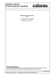
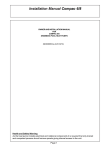
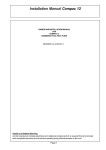
Owner Installation
Manual for
AW631, 831, 1231, 1531
AIR/WATER HEAT PUMPS
(SD526750 Issue 10)
04/11/08
Page 1
Contents
AIR/WATER HEAT PUMPS FOR SWIMMING POOLS .................................................................................... 3
HOW THE HEAT PUMP WORKS .................................................................................................................... 4
INSTALLATION ............................................................................................................................................... 5
1.SITING ......................................................................................................................................................... 5
2.AIR FLOW .................................................................................................................................................... 6
3.PLUMBING ................................................................................................................................................... 7
RECOMMENDED PLUMBING SCHEMATIC .................................................................................................... 9
4. DETERMINING WATER FLOW ...................................................................................................................10
5.ELECTRICAL (MACHINE WIRING AND SUPPLY). ..................................................................................... 11
ELECTRICAL CIRCUIT DIAGRAMS ............................................................................................................... 17
CONTROLS AND INDICATION LAMPS .........................................................................................................19
HEAT PUMP MALFUNCTION ......................................................................................................................... 20
DATA SHEET .................................................................................................................................................. 21
INSTALLATION DRAWINGS .......................................................................................................................... 23
WINTERISING PROCEDURE ......................................................................................................................... 27
START UP PROCEDURE AFTER WINTERISATION....................................................................................... 28
WARRANTY CONDITIONS. ............................................................................................................................ 29
CONTACTING CALOREX ............................................................................................................................... 30
Page 2
AIR/WATER HEAT PUMPS FOR SWIMMING POOLS
MODELS AW631, 831,1231, 1531
The Calorex ‘31’ range of air/water heat pumps is for swimming pool applications and consists
of 4 models. Heat pumps in this manual are designed to heat pool water and spas within the
range of 10°C to 40°C. Standard units are suitable for outdoor pools operating in ambient
temperatures from 7°C to 40°C. Reverse Cycle Defrost models are available with operation
down to -15ºC, these machines are suitable for heating indoor pools or spas all year round.
The water heat exchanger is a full flow type, manufactured from titanium, which is a highly
corrosion resistant material. The heat pumps are suitable for use in fresh water and salt
water pools.The compressors fitted in the heat pumps are the scroll type and are known for
quiet running. With these features the heat pump is designed to have a long, trouble free life.
All units have integral safety devices to protect the heat pump from internal and external
faults. Indicator lamps indicate operating mode. An adjustable digital thermostat controls
water temperature. Also a 6 minute cycle time delay is incorporated.
Page 3
HOW THE HEAT PUMP WORKS
The CALOREX Swimming Pool Heat Pump provides thermodynamic heating by means of a vapour
compression cycle (similar to that employed in a conventional refrigerator), in addition to operating as an active
solar collector.
The EVAPORATOR collects heat from
the outside ambient air, pre-heated by the
sun. With Calorex, swimming pool heat
pumps high volumes of outside air are
drawn into the unit by the fan and expelled
through the evaporator fins. The evaporator
has liquid refrigerant passing through it,
which is at a considerably lower
temperature than the ambient air, therefore
the air gives up its heat to the refrigerant,
which then vaporizes.
This pre-heated vapour now travels to-
Cooled Air Exhaust
The
COMPRESSOR
where it is compressed and
upgraded to a much higher
temperature.
The hot vapour now enters -
Compressor
Swimming
Pool
Pool Water
Pump
Pool Water
Pool Filter
Outside Air
Condenser Heat Tranfered
to Pool Water
Evaporator
(Heat Collector)
Expansion
Device
The EXPANSION DEVICE
and from there, now at low
pressure, it is returned to the
evaporator and the cycle starts
again.
The CONDENSER where it is
surrounded by the pool water. The heat
is given up to the cooler pool water and
the now cooler refrigerant returns to its
former liquid state but still under high
pressure from the compressor.
This pressure is released by passing
the liquid through -
Coefficient of Performance
The efficiency of a Heat Pump is usually called its 'Coefficient of Performance' - (C.O.P.) which is
simply a ratio of heat output to energy input, both being expressed in kW. Thus a Heat Pump
absorbing 1 kW of electricity, collecting 4 kW of energy from the air, and delivering 5 kW of heat to
the pool water is said to have a C.O.P. of 5:1.
Naturally this ratio will vary according to the temperature of the water and the ambient air.
Page 4
INSTALLATION
1.
SITING
a
Ensure heat pump on site is as ordered, i.e. model, electrical supply and factory fitted options.
b
Inspect unit for damage, in particular inspect the evaporator (finned side) to ensure that it is undamaged.
(Minor indentations in the fins do not affect performance). If severely damaged, endorse delivery note in
presence of the driver and send a recorded delivery letter to transport company giving details.
c
Protect unit if installation is delayed.
d
Provide a firm level base capable of supporting operational weight of unit; spread load if mounted on timber
floor.
e
Ensure water cannot collect under unit, it is recommend that units are installed on plinths 100mm above
finished floor level. This also aids condensate drainage.
f
Allow adequate clearance to service panels on unit; recommend 500mm minimum.
g
All Calorex heat pumps are by design as quiet as is practical, however due consideration should be given
to siting the heat pump in order to minimise the noise coming from the machine, for example by positioning
the machine so that the inlet/outlets are parallel to occupied premises.
h
Ensure loose debris such as leaves, grass cuttings, etc will not block air inlet grilles.
i
Consider protection from extreme weather conditions if installed externally, i.e. lean-to-cover or building.
Page 5
2.
AIR FLOW
Due consideration must be given to air flow, i.e. do not obstruct inlet or outlet and ensure discharge air cannot
re-circulate to inlet. (See figure 1)
FIG 1 POSSIBLE POSITIONS OF A CALOREX 31 UNIT
Suitable opening
Suitable opening
CALOREX 31
CALOREX 31
> 50 cm
CALOREX 31
PLANT ROOM
WALL
CALOREX 31
WALL
CALOREX 31
SWIMMING POOL/SPA
MODEL
AW
AW
AW
AW
631
831
1231
1531
TABLE 1
Minimum Free Area m²
Inlet
Discharge
0.1648
0.114
0.2931
0.114
0.2931
0.114
0.3489
0.114
Required Free Areas to provide air flow to
and from heat pumps when installed in an
enclosed area or where required to pass air
through a wall, etc.
Free area is the available area through which air
can pass through a grille or louvres.
Note: If multiple units are installed in an enclosed area then the inlet free areas required for each unit can be
added together to form one inlet aperture. BUT discharge from each unit must be kept separate and must not
be incorporated into one common duct system.
Page 6
3.
PLUMBING
a. Calorex '31' range Heat Pumps have water inlet/outlet connections as follows:
All models have 1½ " BSP parallel, male threads.
The machine is supplied with bungs fitted in the water connection fittings. These need to be removed before
the unit is installed. See Section 4.
b. The Calorex Pool Heat Pump must be connected after the filter in the return pipe to the pool. If an existing
heater is being retained, then the Calorex Heat Pump should be connected between the filter and the other
heater. (See figure 4).
c. Suitable breakable couplings should be installed local to heat pump.
d. If the heat pump is installed at a lower level than pool water then isolation valves should be fitted.
e. Drain valve or plug should be fitted to the lower pipe to facilitate drain down in winter period.
f.
Connections on all models are by BSP parallel, male threaded fittings. These should be hand tightened
only, otherwise damage may result to the threads of the plastic fittings.
g. The condensate drain at the base of the unit collects the condensation from the evaporator fins. This
should be run away to waste via ¾" domestic waste piping. It is therefore necessary to ensure that the
Calorex unit is placed on a level plinth so that the condensate water can run away with adequate fall to
waste ie.½" per foot min and must incorporate a 'u' trap as to not overflow the edges of the drip-tray inside
the machine. See figure 3.
CORRECT DRAINAGE
FOR CONDENSATE
INCORRECT DRAINAGE
FOR CONDENSATE
ELBOW
ADEQUATE FALL
'U' TRAP
FIGURE 3
Page 7
THIS TYPE OF
INSTALLATION
SHOULD BE AVOIDED
h. When the pipework installation is complete the pool pump should be switched on and the system tested for
leaks. Also check the filter gauge to see that there is not an excessive increase in back pressure. If
everything is then working normally the water circulating system is ready to use.
i.
Water circuit to and from unit to be capable of maintaining within specified limits the rate of flow required by
heat pump (see data sheet).
j.
All pipework must be adequately supported with allowance for expansion/contraction especially with plastic
pipework.
k. It is recommended that when installing water systems the last connections to be made in the system
should be the breakable connections to avoid any stresses on to the unit connections.
IMPORTANT
1. All Pool Purifying Devices and Chemical Injection Systems to be fitted down stream of heat pump
unless installation is as per Filter dosing (See figure 4). This includes the practice of dosing
chemicals direct into Skimmer Basket, which results in concentrated corrosive liquids passing over
metal components.
2. Water quality must be maintained as follows:
pH:
Total Alkalinity:
Total Hardness:
Total dissolved solids:
Saline Water
Chlorine - free Cl range
Ozone
Bromine
Baquacil
Aquamatic Ionic Purifier
Tam Pure Purifier
Sherwood Purifier
7.4 ± 0.4
80 - 120 ppm as CaCo3
100 - 300 ppm as CaCo3
Max. 3000 ppm
Maximum concentration 6% wt/wt
1.0 - 3.0 ppm
0.8 - 1.0 ppm
2 - 3 ppm
25 - 50 ppm
Maximum 2 ppm Copper
Maximum 2 ppm Copper
Maximum 2 ppm Copper
3. Maximum pressure of water in heat pump circuit should not exceed 3.5kg/cm2 (50 psi)
Page 8
Page 9
KEY
ISOLATION VALVE
CALOREX
HEAT PUMP
NON
RETURN
VALVE
FIGURE 4
NON RETURN VALVE
FILTER
TO WASTE
SPARE PORT FOR
WINTERISING
FLUSHING
CONNECTION
DEVICE, IF FITTED
SANITISER OR
CHEMICAL DOSING
BREAKABLE COUPLING
CONDENSATE WATER
TO WASTE
TO WASTE FOR
WINTERISING
DRAIN DOWN
ANTI RETURN LOOP
TO BE INCORPORATED,
MINIMUM HEIGHT
100mm ABOVE HEAT PUMP
OULET PORT
(IF SANITISER FITTED)
100mm
AUX HEATER
IF FITTED
THREE WAY VALVE
PUMP
POOL
RECOMMENDED PLUMBING SCHEMATIC
4. DETERMINING WATER FLOW
Plumbing.
The machine must be plumbed in as shown, see diagrams below (a tear off label is attached to the machine on
delivery).
Adjust the flow rate until the flow light is illuminated, giving the correct flow rate. The “adequate flow” symbol
looks like this:
SYMBOL CHART- ALL MACHINES
6 MINS
=I
FLOW LAMP ILLUMINATED,
ADEQUATE FLOW
=0
=I
I=
=0
FLOW LAMP NOT
ILLUMINATED,
INADEQUATE FLOW
POOL/SPA
PUMP
FILTER
6 MINS
I=
WATER HEATING AFTER
6 MINUTE DELAY
REMOVE AND DISPOSE
OF LABEL
D436856 ISS 1
MACHINE LABEL
POOL
WATER OUT
(REMOVE BUNGS
BEFORE INSTALLING
MACHINE)
POOL
WATER IN
(REMOVE BUNG
BEFORE
INSTALLING
MACHINE)
CONDENSATE
DRAIN
MACHINE SIDE
AW631 AND AW831 FLOW RATE 115 LITRES PER MINUTE
AW1231 AND AW1531 FLOW RATE 160 LITRES PER MINUTE
Page 10
5.
ELECTRICAL (MACHINE WIRING AND SUPPLY).
SEE FIGURES 5,6,7 AND 8 FOR PREFERRED METHOD
Use of the Calorex Energy Management Controller will enable greater savings to be made because the
circulating pump need only run when required and this can be at a time preferred by the customer, i.e. in the
Economy 7 period.
All electrical work to be carried out in accordance with l.E.E. standards, latest issue, or local codes of practice
as applicable.
The machine should be installed in line with EMC2004/108/EC.
Protected supply to incorporate fuses (Type GU, FAZC) or motor (type C) circuit breakers to specified rating,
(see Data Sheet). H.R.C. fuses are recommended. An isolator must be fitted within 2m and in sight of
machine.†
All units must be correctly earthed-grounded. An earth leakage trip of the Current operating type (30mA) is
recommended to be fitted to all pool electrics.
INCONSISTENT ELECTRICAL SUPPLY
The following limits of operation must not be exceeded if Calorex machines are to be guaranteed either in
performance or warranty terms:
Minimum
Maximum
Voltage
Single phase machines
207V
253V
Three-phase machines
Cycle frequency
360V
47.5Hz
440V
52.5Hz
N.B. This voltage must be available at the heat pump whilst running.
† Note the isolator must have a minimum of 3mm air gap when turned off.
Three phase units are fitted with a phase protection relay and will not run if phases are
connected incorrectly. A red lamp on the phase rotation relay in the electric box is
illuminated when the phases are correctly connected.
IMPORTANT:The user should be made aware that on all the installations shown by figures 5, 6, 7 and
8 that to work on part of the intallation the supply to all parts of the installation must be
isolated.
Page 11
LOCATION OF ELECTRICAL SUPPLY CONNECTIONS IN 31 RANGE HEAT PUMP
REMOVE THE 6 SCREWS FROM
TOP COVER AND LIFT OFF
3
4
2
INT ERL OCKS
1
5
N L
6
ELECTRIC BOX ACCESS
W ATERPRESSURE
SW ITCH
SO FT ST ART
KIT
ENERGY MANAGEMENT
CO NT ROL LER
FANL
FANN
WAT ER FL OW
SW ITCH
REVERSING
' Y' VRSN
ONLY
VALVE
MAINS IN
BOTH
ENDS
REMOVE THE 6 SCREWS FROM
SERVICE PANEL AND LIFT OFF
FIGURE 5
1 PHASE 230V ~ 1N 50Hz
3 PHASE 400V ~ 3N 50Hz
1
N L
2
L L
N L
3
INTERLOCKS
INTERLOCKS
WATER PRESSURE
SWITCH
SOFT START
KIT
WATER PRESSURE
SWITCH
SOFT START
KIT
ENERGY MANAGEMENT
ENERGY MANAGEMENT
CONTROLLER
CONTROLLER
FAN L
FAN L
FAN N
FAN N
WATER FLOW
WATER FLOW
SWITCH
SWITCH
'Y' VRSN
ONLY
REVERSING
VALVE
Page 12
'Y' VRSN
REVERSING
ONLY
VALVE
FIGURE 6
RECOMMENDED ELECTRICAL INSTALLATION FOR CALOREX HEAT PUMP (1Ø or 3Ø)
WITH SINGLE PHASE WATER PUMP OF MAXIMUM ¾ H.P. AND
ENERGY MANAGEMENT CONTROLLER
SWITCHED FUSE ISOLATOR
WITHIN 2m OF HEAT PUMP AND
SIZED IN ACCORDANCE
WITH DATA SHEET
SINGLE PHASE
13AMP SUPPLY 230v
FUSED TO SUIT
WATERPUMP
N
3
CALOREX ENERGY
MANAGEMENT CONTROLLER
AVAILABLE FROM
CALOREX DISTRIBUTOR
4
N L
7
5
8
L
9 10
L
6
L1
L2
N
5
INTERLOCK
6
L3
CALOREX
HEAT PUMP
SINGLE
PHASE
N
5
INTERLOCK
9
ENERGY MANAGEMENT
CONTROLLER
10
ENERGY MANAGEMENT
CONTROLLER
L
SOFT START
9
CALOREX
HEATPUMP
THREE PHASE
10
SOFT START
WATER PUMP
MAXIMIUM 3/4HP
SINGLE PHASE
N
6
FIGURE 7
RECOMMENDED ELECTRICAL INSTALLATION FOR CALOREX HEAT PUMP (1Ø or 3Ø)
WITH SINGLE PHASE WATER PUMP LARGER THAN ¾ H.P. AND
ENERGY MANAGEMENT CONTROLLER
SWITCHED FUSE ISOLATOR
WITHIN 2m OF HEAT PUMP AND
SIZED IN ACCORDANCE
WITH DATA SHEET
SINGLE PHASE
13AMP SUPPLY 230v
FUSED TO SUIT
WATERPUMP
N
SINGLE PHASE
SUPPLY TO SUIT
CAPACITY OF
WATER PUMP
L
N
CALOREX ENERGY
MANAGEMENT
CONTROLLER
AVAILABLE FROM
CALOREX DISTRIBUTOR
3
N L
4
7
5
8
L
9 10
6
N
L
INTERLOCK
4 POLE N/O STARTER
WITH OVERLOAD AND
230v 50Hz COIL RATED
TO SUIT WATER PUMP
6
CALOREX
HEAT PUMP
SINGLE
PHASE
N
5
INTERLOCK
9
10
ENERGY MANAGEMENT
CONTROLLER
SOFT START
SOFT START
L
L
N
L2
5
ENERGY MANAGEMENT
CONTROLLER
N
L1
L3
VOLT FREE
AUXILLARY
CONTACT
N/O
L
L
N
WATER PUMP
MAXIMIUM 3/4HP
SINGLE PHASE
Page 13
6
9
10
CALOREX
HEATPUMP
THREE PHASE
FIGURE 8
RECOMMENDED ELECTRICAL INSTALLATION FOR CALOREX HEAT PUMP (1Ø or 3Ø)
WITH THREE PHASE WATER PUMP AND ENERGY MANAGEMENT CONTROLLER
THREE PHASE
SUPPLY TO SUIT
CAPACITY OF
WATER PUMP
L3 L2 L1
SINGLE PHASE
13 AMP SUPPLY 230v
FUSED AT 1 AMP
SWITCHED FUSE ISOLATOR WITHIN
2m OF HEAT PUMP AND SIZED IN
ACCORDANCE WITH DATA SHEET
N
CALOREX ENERGY
MANAGEMENT
CONTROLLER
AVAILABLE FROM
CALOREX
DISTRIBUTOR
3
N L
7
4
5
8
L
9 10
L1
L
6
L2
N
VOLT FREE
AUXILLARY
CONTACT N/O
5
INTERLOCK
6
ENERGY MANAGEMENT
CONTROLLER
L3 L2 L1
L
4 POLE N/O STARTER WITH
OVERLOAD AND 230v 50Hz COIL
RATED TO SUIT WATER PUMP
SOFT
START
L1
L3
N
INTERLOCK
6
9
10
5
ENERGY MANAGEMENT
CONTROLLER
9
10
SOFT START
N
L2
L3
CALOREX
HEAT PUMP
SINGLE PHASE
WATER PUMP
THREE PHASE
Page 14
CALOREX
HEAT PUMP
THREE PHASE
FIGURE 9
RECOMMENDED ELECTRICAL INSTALLATION FOR CALOREX HEAT PUMP (1Ø or 3Ø)
WITH SINGLE PHASE WATER PUMP OF MAXIMUM ¾ H. P
(NOTE: Method shown in Fig 9. is a preferred system due to incorporated starter and interlock)
SWITCHED FUSE ISOLATOR
WITHIN
2m OF HEAT PUMP AND SIZED IN
ACCORDANCE WITH DATA SHEET
SINGLE PHASE
13 AMP SUPPLY 230v
FUSED TO SUIT
WATER PUMP
N
L
L
L1
N
L2
L3
5
INTERLOCK
6
CALOREX
HEAT PUMP
SINGLE PHASE
9
L
CALOREX
HEAT PUMP
THREE PHASE
9
10
WATER PUMP
MAXIMIUM 3/4 HP
SINGLE PHASE
N
N
5
INTERLOCK
6
10
SOFT
START
SOFT START
FIGURE 10
RECOMMENDED ELECTRICAL INSTALLATION FOR CALOREX HEAT PUMP(1Ø or 3Ø)
WITH SINGLE PHASE WATER PUMP OF LARGER THAN ¾ H.P.
SINGLE PHASE
SUPPLY TO SUIT
CAPACITY OF
WATER PUMP
L
SWITCHED FUSE ISOLATOR WITHIN
2m OF HEAT PUMP AND SIZED IN
ACCORDANCE WITH DATA SHEET
N
N
L
L
L1
L2
N
VOLT FREE
AUXILLARY
CONTACT N/O
L3
5
INTERLOCK
6
CALOREX
HEAT PUMP
SINGLE PHASE
N
5
INTERLOCK
6
L
L
N
4 POLE N/O STARTER WITH
OVERLOAD AND 230v 50Hz COIL
RATED TO SUIT WATER PUMP
N
L
9
9
10
10
SOFT START
SOFT START
N
L
N
WATER PUMP
MORE THAN 3/4 HP
SINGLE PHASE
Page 15
CALOREX
HEAT PUMP
THREE PHASE
FIGURE 11
RECOMMENDED ELECTRICAL INSTALLATION FOR CALOREX HEAT PUMP(1Ø or 3Ø)
WITH THREE PHASE WATER PUMP
THREE PHASE
SUPPLY TO SUIT
CAPACITY OF
WATER PUMP
L3
L2
SWITCHED FUSE ISOLATED WITHIN
2m OF HEAT PUMP AND SIZED IN
ACCORDANCE WITH DATA SHEET
L3
N
L
L1
L1
L2
N
VOLT FREE
AUXILLARY
CONTACT N/O
L3
5
INTERLOCK
6
CALOREX
HEAT PUMP
SINGLE PHASE
N
INTERLOCK
5
6
9
L3
L2
9
L
L1
10
4 POLE N/O STARTER WITH
OVERLOAD AND 230v 50Hz COIL
RATED TO SUIT WATER PUMP
10
SOFT START
SOFT START
N
L1
L2
WATER PUMP
THREE PHASE
L3
Page 16
CALOREX
HEAT PUMP
THREE PHASE
Page 17
6
4
7
6
5
8
L3 L2 L1
4
2
3
1
L1
L2
DEFROST
LIGHT
HOURS
RUN METER
IF FITTED
11
14
BLOCK
MAINS LIGHT
TERMINAL
FAULT
LIGHT
POOL STAT
N
9
SMART CLOCK
FEED TERMINALS
L
10
CONTROL
MOTOR
PHASE
STARTER
ROTATION
RELAY
5
6
L3
INTERLOCK
TERMINALS
WATER
PRESSURE
SWITCH
(IF FITTED)
HP
SWITCH
LP
SWITCH
SOFT START
THERMAL
OVERLOAD &
FAULT LIGHT
IF FITTED
WATER FLOW
SWITCH
2
DEFROST
STAT
11 10 1
SENSOR
DELAY
TIMER
CONTACTOR
4
7
R1
SOFT
START
IF
FITTED
U(R)
FAN
COMPRESSOR
A
B
NEUTRAL
WATER FLOW
LIGHT
FAN CAPACITOR
W(C)
V(S)
LIVE
1
2
L
N
9
6
5
8
7
10
6
4
CONTROL FUSE
SMART CLOCK
FEED TERMINALS
WATER
PRESSURE
SWITCH
(IF FITTED)
INTERLOCK
TERMINALS
HP
SWITCH
LP
SWITCH
SOFT START
THERMAL
OVERLOAD
& FAULT
LIGHT
IF FITTED
WATER FLOW
SWITCH
11 10
SENSOR
DEFROST
STAT
DELAY
TIMER
TERMINAL
BLOCK
FAULT
LIGHT
POOL STAT
RELAY/HARD
START CAP
(IF FITTED)
RUN CAP
MAINS LIGHT
DEFROST
LIGHT
HOURS
RUN METER
IF FITTED
CONTACTOR
R1
7
4
SOFT
START
IF
FITTED
U(R)
FAN
W (C)
A
B
WATER FLOW
LIGHT
NEUTRAL
COMPRESSOR
FAN CAPACITOR
V(S)
ELECTRICAL CIRCUIT DIAGRAMS
AW631, 831, 1231 AL SINGLE PHASE (230V ~ 1 N 50Hz)
AW 631, 831, 1231 1531BL THREE PHASE ( 400V ~ 3 N 50Hz)
L3
L2
L1
1
2
Page 18
1
3
5
STARTER
2
4
6
CONTROL MOTOR
SMART CLOCK
FEED TERMINALS
POOL PUMP
INTERLOCK
TERMINALS
9
6
5
8
7
10
6
4
L1
L2
L3
RELAY
11
14
MAINS LIGHT
TERMINAL
BLOCK
LIGHT
FAULT
POOL STAT
HOURS
RUN
METER
IF FITTED
PHASE ROTATION
L
N
HP
SWITCH
LP
SWITCH
SOFT START
THERMAL
OVERLOAD
& FAULT
LIGHT
IF FITTED
WATER FLOW
SWITCH
11 10
SENSOR
DELAY
TIMER
CONTACTOR
3
2
4
1
R1
DEFROST
CONTROL
STAT
SOFT
START
IF
FITTED
7
4
R(U)
A
B
WATER FLOW
LIGHT
FAN CAPACITOR
FAN
DEFROST
LIGHT
NEUTRAL
COMPRESSOR
REVERSING VALVE
C(W)
S(V)
LIVE
1
2
L
N
9
6
5
8
7
10
6
4
CONTROL FUSE
FEED TERMINALS
SMART CLOCK
(IF FITTED)
PRESSURE SWITCH
WATER
INTERLOCK
TERMINALS
HP
SWITCH
LP
SWITCH
SOFT START
THERMAL
OVERLOAD
& FAULT
LIGHT
IF FITTED
SWITCH
WATER FLOW
11 10
SENSOR
DELAY
TIMER
TERMINAL
BLOCK
FAULT
LIGHT
POOL STAT
1
4
2
3
DEFROST
CONTROL
STAT
RELAY/HARD
START CAP
(IF FITTED)
RUN CAP
MAINS LIGHT
HOURS
RUN METER
IF FITTED
CONTACTOR
S [V]
R1
7
4
C[W]
A
B
WATER FLOW
LIGHT
FAN
DEFROST
LIGHT
R[U]
NEUTRAL
COMPRESSOR
REVERSING VALVE
SOFT
START
IF
FITTED
AW631, 831, 1231 ALY SINGLE PHASE (230V ~ 1 N 50Hz)
AW 631, 831, 1231 1531BLY THREE PHASE ( 400V ~ 3 N 50Hz)
CONTROLS AND INDICATION LAMPS
THERMOSTAT
Adjustable digital thermostat, controls pool water temperature at the required level.
Press and release key ‘P’ to display required temperature, to alter required temperature press up or down
symbols. After 5 seconds display will revert to actual water temperature.
NON FUNCTIONAL ON THIS APPLICATION
INCREASE SET POINT
U
P
DECREASE SET POINT
ACCESS SET POINT
INDICATOR LAMPS "AW" POOL HEATERS
MAINS
RED
Electrical supply on
FAULT
AMBER
Internal or external fault condition
DEFROST
WHITE
Defrost Mode
WATER FLOW
GREEN
Water flowing at adequate rate
CONSOLE LABEL
Page 19
HEAT PUMP MALFUNCTION
WARNING: Isolate machine electrically before entering machine or removing panels.
The user check list should be carried out before initiating a service call.
Do not attempt to interfere with any internal control settings as these have been factory calibrated and sealed.
If in doubt or if advice required contact Calorex Service Department.
Telephone (01621) 857171 or 856611
USER CHECK LIST
LAMP
ACTION
UNIT DOES NOT OPERATE
MAINS
RED
OFF
FAULT
AMBER
OFF
DEFROST
WHITE
OFF
WATER FLOW
GREEN
OFF
MAINS
RED
ON
FAULT
AMBER
OFF
DEFROST
WHITE
OFF
WATER FLOW
GREEN
OFF
RED
ON
MAINS
FAULT
AMBER
OFF
DEFROST
WHITE
OFF
WATER FLOW
GREEN
OFF
MAINS
RED
ON
FAULT
AMBER
ON
DEFROST
WHITE
OFF
WATER FLOW
GREEN
OFF
Check mains supply- external fuses - isolator etc.
Water flow inadequate
First check water flow, then
Check unit control fuse on single phase m achine.
Check MCB on three phase machine.
Check water and air flows are not restricted.
Check thermal cut out on Soft Start if fitted and that
air flow is not restricted. Check unit control fuse on
single phase machine. Check MCB on three phase
machine.
FAN ON COMPRESSOR OFF
MAINS
RED
ON
Unit on defrost (heating mode) check that air
temperature is not below 7°C.
FAULT
AMBER
OFF
Check evaporator is clean.
DEFROST
WHITE
ON
WATER FLOW
GREEN
ON
UNIT OPERATES INTERMITTENTLY
ON
Check water and air flows are not restricted, and
that electrical supply is adequate.
AMBER
ON/OFF
Check gas charge and airflow to machine.
DEFROST
WHITE
OFF
WATER FLOW
GREEN
OFF
MAINS
RED
FAULT
Page 20
DATA SHEET
HEAT PUMPS FOR OUTDOOR POOLS
SUMMER SEASON (AL, BL)
MODEL
Units
AW631
AW831
AW1231
AW1531
HEAT TO POOL WATER
AMBIENT 10°C, WATER 24°C
kWhr
AMBIENT 20°C, WATER 24°C
kWhr
7.2
9.9
12.4
17.7
9.2
12.5
15.6
22.4
ELECTRICITY
ELECTRICAL SUPPLY 1 PHASE
ELECTRICAL SUPPLY 3 PHASE
230V/~1N/ 50Hz
400V/~3N/ 50Hz
TOTAL POWER CONSUMED
AMBIENT 10°C, WATER 24°C
kWhr
1.8
2.3
3.1
AMBIENT 20°C, WATER 24°C
kWhr
2.0
2.5
3.3
4.3
MIN SUPPLY CAPACITY (Max F.L.A.) 1 ph N:MIN SUPPLY CAPACITY (Max F.L.A.) 3 ph N:-
A
A
14.3
6.0
17.4
6.2
19.0
8.0
N/A
13.0
MAX SUPPLY FUSE 1 ph N:-
A
20.0
25.0
30.0
N/A
MAX SUPPLY FUSE 3 ph N:-
A
10.0
10.0
15.0
18.0
WATER FLOWS ETC
POOL WATER FLOW RATE:-
l/mn
115
115
160
160
POOL WATER PRESSURE DROP (@ Rated Flow):-
m hd
1.1
1.1
2.9
2.9
bar
3.5
3.5
3.5
3.5
POOL WATER CONNECTIONS:-
inches
1 1/2" BSPM
1 1/2" BSPM
1 1/2" BSPM
1 1/2" BSPM
CONDENSATE DRAIN CONNECTIONS:-
inches
MAX WORKING PRESSURE POOL WATER:-
COMPRESSOR
NOMINAL POWER CONSUMED
4.2
3/4"BSPM STUD 3/4"BSPM STUD 3/4"BSPM STUD 3/4"BSPM STUD
kWhr
1.8
2.14
2.6
3.8
L.R.A. 1 ph N:-
A
66
63
100
N/A
R.L.A. 1 ph N:SOFT START AMPS 1 ph N:-
A
A
11.4
29
14
31
16.6
35
N/A
N/A
L.R.A. 3 ph N:-
A
32
30
48
48
R.L.A. 3 ph N:-
A
4
4.7
7.3
10
SOFT START AMPS 3 ph N:-
A
14
14
17
25
4700
MAIN FAN
AIR FLOW (Anemometer @ air on grille. Wet evaporator):-
m³/hr
1800
2700
3000
mm Wg
0
0
0
0
A
0.7
0.7
0.97
2
kg
1.6
2.05
2.2
2.45
PHYSICAL DIMENSIONS
WIDTH (Unpacked):-
mm
1076
1076
1076
1200
DEPTH (Unpacked):-
mm
485
485
485
485
HEIGHT (Unpacked):-
mm
1255
1255
1355
1355
WEIGHT (Unpacked):-
kg
126
134
144
158
MAX EXTERNAL STATIC PRESSURE:F.L.A. 1 ph N:-
GENERAL DATA
HERMETIC SYSTEM
GAS CHARGE
R407c
For Accurate Application Sizing Consult CALOREX Heat Pumps Ltd.
NOTES:1) Weight and dimensions nett
2) Performance design Iimitations
Ambient = 7°C min, 40°C max
Water = 10°C min, 40°C max
3) Pool water to have correct balance, pH 7.4 ± 0.4 Free Chlorine 1.0 - 3.0 ppm
4) Allow 500mm clearance to service panels
5) Calorex reserve the right to change or modify models without prior notice.
6) R407c Global warming potential (GWP) 1700.
1mm WG = 9.8 Pa
1m hd = 1.4 psi
1L/min = 0.22 gall/min
Page 21
HEAT PUMPS FOR OUTDOOR POOLS
REVERSE CYCLE DEFROST (ALY, BLY)
MODEL
Units
AW631
AW831
AW1231
AW1531
HEAT TO POOL WATER
AMBIENT 10°C, WATER 24°C :-
kWhr
7.2
9.9
12.4
17.7
ELECTRICAL
ELECTRICAL SUPPLY 1 PHASE
230V/~1N/50Hz
400V/~3N/50Hz
ELECTRICAL SUPPLY 3 PHASE
TOTAL POWER CONSUMED:AMBIENT 10°C, WATER 24°C :-
kWhr
1.8
2.3
3.1
AMBIENT 20°C, WATER 24°C :-
kWhr
2.0
2.5
3.3
4.3
MIN SUPPLY CAPACITY (Max F.L.A.) 1 ph N:-
amps
14.3
17.4
19.0
N/A
MIN SUPPLY CAPACITY (Max F.L.A.) 3 ph N:-
amps
6.0
6.2
8.0
13.0
MAX' SUPPLY FUSE 1 ph N:MAX' SUPPLY FUSE 3 ph N:-
amps
amps
20.0
10.0
25.0
10.0
30.0
15.0
N/A
18.0
WATER FLOWS ETC
POOL WATER FLOW RATE:-
litres/min
115
115
160
160
POOL WATER PRESSURE DROP (@ Rated Flow):-
metres hd
1.0
1.0
2.0
2.0
MAX WORKING PRESSURE POOL WATER:POOL WATER CONNECTIONS:-
bar
inches
3.5
1 1/2" BSPM
3.5
1 1/2" BSPM
3.5
1 1/2" BSPM
3.5
1 1/2" BSPM
CONDENSATE DRAIN CONNECTIONS:-
inches
COMPRESSOR
NOMINAL POWER CONSUMED:LRA.- 1 ph N:-
kWhr
amps
1.8
66
2.14
63
2.6
100
RLA:- 1 ph N:-
amps
11.4
14
16.6
N/A
SOFT START AMPS 1 ph N:-
amps
29
31
35
N/A
LRA:- 3ph N:-
amps
32
30
48
48
RLA: -3 ph N:-
amps
4
4.65
7.3
10
SOFT START AMPS 3 ph N:-
amps
14
14
17
25
4700
MAlN FAN
AIR FLOW (Anemometer @ air on grille. Wet evaporator):-
4.2
3/4" BSPM STUD 3/4" BSPM STUD 3/4" BSPM STUD 3/4" BSPM STUD
3.8
N/A
m³/hr
1800
2700
3000
mm Wg
0
0
0
0
amps
0.7
0.7
0.97
2
kg
2.31
3.0
4.5
4.5
PHYSICAL DIMENSIONS
WIDTH (Un-packed):-
mm
1076
1076
1076
1200
DEPTH (Un-packed):-
mm
485
485
485
485
HEIGHT (Un-packed):-
mm
1255
1255
1355
1355
WEIGHT (Un-packed) :-
kg
133
142
157
170
MAX EXTERNAL STATIC PRESSURE :FLA:- 1 ph N:-
GENERAL DATA
HERMETIC SYSTEM
GAS CHARGE
R407c
For Accurate Application Sizing Consult CALOREX Heat Pumps Ltd.
NOTES:
1) Weight and dimensions nett
2) Performance design Iimitations
Ambient = -15°C min, 35°C max
Water = 10°C min, 40°C max
3) Pool water to have correct balance, pH 7.4 ± 0.4 Free Chlorine 1.0 - 3.0 ppm
4) Allow 500mm clearance to service panels
5) Calorex reserve the right to change or modify models without prior notice.
6) R407c Global Warming Potential (GWP) 1700.
1mm WG = 9.8 Pa
1m hd = 1.4 psi
1L/min = 0.22 gall/min
Page 22
1245.00
450.00
190.00
*
*
816.00
*
DIA 472.00
*
603.00
1025.00
30.00
MAINS IN
POSITION
CONSOLE
954.00
4 HOLES Ø 8,6 TO SECURE
UNIT TO THE GROUND
110.00
184.00
AW631
WATER IN/OUT 1 1/2” BSPM STUBS
CONDENSATE 3/4” BSPM
719.00
Page 23
479.00
400.00
350.00
WATER
IN
485.00
WATER
OUT
65.00
CONDENSATE
191.00
505.00
AIR ON
501.00
716.00
AIR OFF
ALTERNATIVE
MAINS IN
POSITION
INSTALLATION DRAWINGS
1245.00
450.00
190.00
*
*
816.00
*
DIA 472.00
*
603.00
1025.00
MAINS IN
POSITION
CONSOLE
719.00
954.00
4 HOLES DIA 8.6 TO SECURE
MACHINE TO THE GROUND.
110.00
479.00
30.00
400.00
350.00
WATER
IN
485.00
WATER
OUT
65.00
CONDENSATE
95.00
807.00
AIR ON
AIR OFF
552.00
665.00
AW831
WATER IN/OUT 1 1/2” BSPM STUBS
CONDENSATE 3/4” BSPM
184.00
Page 24
ALTERNATIVE
MAINS IN
POSITION
1345.00
450.00
Page 25
190.00
558.90
472.00
*
*
*
*
816.00
1025.00
30.00
1028.89
4 HOLES DIA 8.6 TO SECURE
MACHINE TO THE GROUND
MAINS IN
POSITION
CONSOLE
816.00
110.00
662.00
496.00
AW1231
WATER IN/OUT 1 1/2” BSPM STUBS
CONDENSATE 3/4” BSPM
401.00
355.00
WATER IN
WATER OUT
485.00
CONDENSATE
553.00
95.00
65.00
762.00
181.00
820.00
AIR ON
AIR OFF
ALTERNATIVE
MAINS IN POSITION
1345.00
450.00
Page 26
240.00
*
*
880.00
*
*
567.00
DIA 472.00
30.00
1033.00
MAINS IN
POSITION
CONSOLE
181.00
110.00
4 HOLES DIA 8.6 TO SECURE
MACHINE TO THE GROUND
816.00
1115.00
662.00
496.00
AW1531
WATER IN/OUT 1½” BSPM STUBS
CONDENSATE 3/4” BSPM STUB
401.00
355.00
WATER
IN
WATER
OUT
485.00
CONDENSATE
553.00
104.00
65.00
762.00
909.00
AIR ON
AIR OFF
ALTERNATIVE
MAINS IN POSITION
WINTERISING PROCEDURE
WARNING. Isolate machine before removing covers! The heat pump
embodies electrical and rotational equipment, it is recommended for your
own safety that a competent person carries out the following procedure
ALL MODELS
Objective
To provide frost protection
To eliminate corrosion problems
To inhibit electrical components
1. Switch off electric supply to heat pump.
2. Remove external fuses and keep in safe place away from heat pump to prevent accidental operation of heat
pump.
3. Ensure water circulation pump is switched off.
4. Drain water from heat pump by:
a. drain valve if fitted
b. disconnecting pipework to and from heat pump
5. Flush through water circuit in heat pump by using CLEAN TAP WATER (NOT POOL WATER) via hose into
outlet connection - run the hose for 10 minutes minimum; use spray nozzle if available.
6. Allow to drain - when drained, fit plastic bags secured by elastic bands over water connections.
7. Uncover electrical enclosure (see page 12) and liberally spray interior of unit, with moisture-repellant
aerosol WD40 or similar; reseal enclosure.
8. If heat pump located outside, protect from weather by covering with VENTILATED cover. Do not use plastic
sheet as condensation could occur within unit.
N.B.
If this procedure is not adopted and frost or corrosion damage results then the
warranty will become invalid.
Page 27
START UP PROCEDURE AFTER WINTERISATION
1. Replace covers (if not fitted).
2. Remove front grille .Using a soft brush clean finned surfaces of heat pump. Replace panel.
3. Remove plastic covers on water connections and reconnect water piping or close drain valve.
4. Start up water circulating pump and leave running for at least 1/4 hour to establish flow and enable any air
in piping to escape.
5. Replace fuses to heat pump circuit.
6. Switch on heat pump.
7. Check control thermostat is set to required pool temperature.
8. Check pool water daily to ensure it is at correct pH and has correct chemical balance. See Section 3
Plumbing.
Page 28
WARRANTY CONDITIONS.
The following exclusions apply to the Warranty given by Calorex Heat Pumps Ltd. No claims will be accepted if : -
1. The heat pump is incorrectly sized for the application.
2. The heat pump is installed in any way that is not in accordance with the current procedures as defined by
Calorex Heat Pumps Ltd.
3. The heat pump has been worked upon or is adjusted by anyone other than a person authorised to do so
by Calorex Heat Pumps Ltd.
4. The air flow to and from the machine is outside the specified limits.
5. The water flow through the machine is outside the specified limits.
6. The water pH level and/or chemical balance is outside the following limits:Acidity
pH:
7.4 ± 0.4
Total Alkalinity, as CaCo3
Total Hardness, as CaCo3
ppm
ppm
80 -120
100-300
Total Dissolved Solids:
Maximum Salt Content:
ppm
wt/wt
MAX 3000
6%
Free Chlorine Range:
ppm
1.0 - 3.0
Superchlorination:
Bromine:
Baquacil:
ppm
ppm
ppm
MAX 30 for MAX 24hrs
2-3
25 - 50
Ozone:
*Maximum Copper Content:
ppm
ppm
0.8 - 1.0
MAX 2
*Aquamatic Ionic Purifier:
ppm
MAX 2
*Tarn Pure Purifier:
*Sherwood Purifier:
ppm
ppm
MAX 2
MAX 2
7. The heat pump has suffered frost damage.
8. The electrical supply is insufficient or in anyway incorrect.
Page 29
CONTACTING CALOREX
IF IN ANY DOUBT PLEASE ASK
Note:- The Reply Paid Warranty Registration Card must be returned, to ensure that the correct warranty is given.
If you do not find a Registration Card with your Heat Pump please contact the Calorex Service Department giving
your name, address and serial number of your heat pump. A card will be sent to you for completion.
Email: [email protected]
Website: http//www.calorex.com
01621 857171
01621 856611
Please give MODEL NUMBER and SERIAL NUMBER of your heat pump when making technical or service
enquiries. This will assist in correct diagnosis and ensure service can be provided with the minimum
delay
Page 30