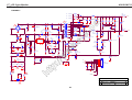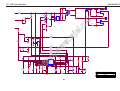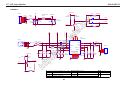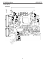
1
17" LCD Color Monitor
ASUS VW171S
ne
t
Service
Service
Service
el.
Horizontal Frequency
30-82 KHz
TABLE OF CONTENTS
Page
Description
Page
w.
wj
Description
6.Schematic……………......................................20
Revision List.…........................................……......2
6.1.Main Board………..........................................20
Important Safety Notice.……..................……......3
6.2.Power Board...……....................................24
1.Monitor Specification..............................………........4
6.3. Audio Board...……......................................26
2.LCD Monitor Description…………………………….......5
7.PCB Layout..………….......................................27
3.Operation Instruction…………...............……...........6
7.1.Main Board………........................................27
3.1.General Instructions...........................…...........6
7.2.Power Board….......................................30
3.2.Control Button…………….…..............……...............6
7.3.Audio Board...…….......................................32
3.3.OSD Menu…………….…...........................…............7
7.4.Key Board…………….....................................32
4.Input/Output Specification............……………............11
8.Maintainability……….......................................33
4.1.Input Signal Connector............………….................11
8.1.Equipments and Tools Requirement...............33
4.2.Power Supply Requirements...............................11
8.2.Trouble Shooting…………..............................34
4.3.Factory Preset Display Modes..........................12
9.White-Balance, Luminance adjustment.............40
4.4.Panel Specification.....………………..................13
10.Monitor Explode View………..…….…............42
5.Block Diagram…..…...................…………................16
11.BOM List…………………………………............43
5.1.Software Flow Chart…………………....….......16
12.Different Part List………………………….........54
ht
tp
://
ww
Table Of Contents.......……..............................…........1
5.2.Electrical Block Diagram……………..….......18
SAFETY NOTICE
ANY PERSON ATTEMPTING TO SERVICE THIS CHASSIS MUST FAMILIARIZE HIMSELF WITH THE
CHASSIS AND BE AWARE OF THE NECESSARY SAFETY PRECAUTIONS TO BE USED WHEN SERVICING
ELECTRONIC EQUIPMENT CONTAINING HIGH VOLTAGES.
CAUTION: USE A SEPARATE ISOLATION TRANSFOMER FOR THIS UNIT WHEN SERVICING
1
17" LCD Color Monitor
ASUS VW171S
Revision List
Version
Release Date
Revision History
TPV Model Name
A00
Jul.27, 2007
Initial release
T77HMRDD8WUSAN
T77GMRHT8WUSAN
Oct.22, 2007
Add new BOM in Item12
T77HMRDD8WUSAZ
tp
://
ww
w.
wj
el.
ne
t
T77HMRDT8WUSAN
ht
A01
2
17" LCD Color Monitor
ASUS VW171S
Important Safety Notice
Proper service and repair is important to the safe, reliable operation of all AOC Company Equipment. The service
procedures recommended by AOC and described in this service manual are effective methods of performing service
operations. Some of these service operations require the use of tools specially designed for the purpose. The
special tools should be used when and as recommended.
t
It is important to note that this manual contains various CAUTIONS and NOTICES which should be carefully read in
order to minimize the risk of personal injury to service personnel. The possibility exists that improper service
methods may damage the equipment. It is also important to understand that these CAUTIONS and NOTICES ARE
NOT EXHAUSTIVE. AOC could not possibly know, evaluate and advise the service trade of all conceivable ways in
which service might be done or of the possible hazardous consequences of each way. Consequently, AOC has not
undertaken any such broad evaluation. Accordingly, a servicer who uses a service procedure or tool which is not
recommended by AOC must first satisfy himself thoroughly that neither his safety nor the safe operation of the
equipment will be jeopardized by the service method selected.
Hereafter throughout this manual, AOC Company will be referred to as AOC.
ne
WARNING
el.
Use of substitute replacement parts, which do not have the same, specified safety characteristics may create shock,
fire, or other hazards.
w.
wj
Under no circumstances should the original design be modified or altered without written permission from AOC.
AOC assumes no liability, express or implied, arising out of any unauthorized modification of design.
Servicer assumes all liability.
ww
FOR PRODUCTS CONTAINING LASER:
DANGER-Invisible laser radiation when open AVOID DIRECT EXPOSURE TO BEAM.
CAUTION-Use of controls or adjustments or performance of procedures other than those specified herein may
result in hazardous radiation exposure.
CAUTION -The use of optical instruments with this product will increase eye hazard.
ht
tp
://
TO ENSURE THE CONTINUED RELIABILITY OF THIS PRODUCT, USE ONLY ORIGINAL MANUFACTURER'S
REPLACEMENT PARTS, WHICH ARE LISTED WITH THEIR PART NUMBERS IN THE PARTS LIST SECTION OF
THIS SERVICE MANUAL.
Take care during handling the LCD module with backlight unit
-Must mount the module using mounting holes arranged in four corners.
-Do not press on the panel, edge of the frame strongly or electric shock as this will result in damage to the screen.
-Do not scratch or press on the panel with any sharp objects, such as pencil or pen as this may result in damage to
the panel.
-Protect the module from the ESD as it may damage the electronic circuit (C-MOS).
-Make certain that treatment person’s body is grounded through wristband.
-Do not leave the module in high temperature and in areas of high humidity for a long time.
-Avoid contact with water as it may a short circuit within the module.
-If the surface of panel becomes dirty, please wipe it off with a soft material. (Cleaning with a dirty or rough cloth may
damage the panel.)
3
17" LCD Color Monitor
ASUS VW171S
ht
tp
://
ww
w.
wj
el.
ne
t
1. Monitor Specifications
4
17" LCD Color Monitor
ASUS VW171S
2. LCD Monitor Description
The LCD monitor will contain a main board, an audio board, a power board and a key board which house the flat
panel control logic, brightness control logic and DDC.
The power board will provide AC to DC Inverter voltage to drive the backlight of panel and the main board chips
each voltage.
Monitor Block Diagram
Flat Panel and
CCFL Drive.
t
CCFL backlight
RS232 Connector
ne
Power board
Main Board
For white balance
el.
(Include: adapter, inverter)
Audio Board
HOST Computer
ht
tp
://
ww
100V-240V
mode
Key Board
w.
wj
AC-IN
adjustment in factory
5
Video signal, DDC
17" LCD Color Monitor
ASUS VW171S
3. Operating Instructions
3.1 General Instructions
Press the power button to turn the monitor on or off. The other control buttons are located at the front of the
panel of the monitor.
By changing these settings, the picture can be adjusted to your personal preferences.
-
The power cord should be connected.
-
Connect the video cable from the monitor to the video card.
-
Press the power button to turn on the monitor, the power indicator will light up.
3.2 Control Buttons
ht
tp
://
ww
w.
wj
el.
ne
t
3.2.1 Key Control
6
17" LCD Color Monitor
ASUS VW171S
3.3 OSD Menu
ht
tp
://
3.3.1 How to Reconfigure
ww
w.
wj
el.
ne
t
3.2.2 Key Function
7
17" LCD Color Monitor
ASUS VW171S
ht
tp
://
ww
w.
wj
el.
ne
t
3.3.2 OSD Function Introduction
8
ASUS VW171S
ht
tp
://
ww
w.
wj
el.
ne
t
17" LCD Color Monitor
9
ASUS VW171S
ht
tp
://
ww
w.
wj
el.
ne
t
17" LCD Color Monitor
10
17" LCD Color Monitor
ASUS VW171S
4. Input/ Output Specification
4.1 Input Signal Connector
Analog connectors
Description
Pin No.
Description
1.
Red Video
9.
+5V
2.
Green Video
10.
Logic Ground
3.
Blue Video
11.
Monitor Ground
4.
Monitor Ground
12.
DDC-Serial Data
5.
DDC-Return
13.
H-Sync
6.
Red Ground
14.
V-Sync
7.
Green Ground
15.
DDC-Serial Clock
8.
Blue Ground
A/C Line frequency range
Input Voltage transients
11
15
100 V ~ 240 V
50 ± 3Hz, 60 ± 3Hz
90-264 voltage AC for 10 sec @40℃
1.5A max at 100V; 0.8A max at 240 V
Peak surge current
tp
Leakage current
< 60A peak at 240 VAC and cold starting
://
Current
10
ww
A/C Line voltage range
5
6
w.
wj
4.2 Power Supply Requirements
1
el.
VGA connector layout
ne
t
Pin No.
ht
Power line surge
< 30A peak at 120VAC and cold starting
< 3.5mA
No advance effects (no loss of information or defect)
with a maximum of 1 half-wave missing per second
11
ASUS VW171S
ht
tp
://
ww
w.
wj
el.
ne
t
17" LCD Color Monitor
4.3 Factory Preset Display Modes
12
17" LCD Color Monitor
4.4 Panel Specification
ASUS VW171S
4.4.1 General Features
_ 17.0 WXGA+ for Monitor application
_ High Resolution: 1440*900
_ 2-ch LVDS interface system
_ LCD Timing Controller
_ Wide Viewing Angle
_ RoHS compliance
ht
tp
://
ww
w.
wj
el.
ne
t
4.4.2 General Specification
13
17" LCD Color Monitor
ASUS VW171S
ht
tp
://
ww
w.
wj
el.
ne
t
4.4.3 Optical Characteristics
14
17" LCD Color Monitor
ASUS VW171S
4.4.4 Electrical Characteristics
ne
t
(1) TFT-LCD
ht
tp
://
ww
w.
wj
el.
(2) Backlight
15
17" LCD Color Monitor
ASUS VW171S
5. Block Diagram
5.1 Software Flow Chat
1
Y
2
3
N
t
4
ne
N
5
el.
Y
w.
wj
6
N
7
8
ww
Y
://
9
tp
10
11
Y
12
ht
N
N
13
Y
Y
14
15
Y
17
18
N
N
19
Y
16
N
16
17" LCD Color Monitor
ASUS VW171S
1) MCU initialize.
2) Is the EPROM blank?
3) Program the EPROM by default values.
4) Get the PWM value of brightness from EPROM.
5) Is the power key pressed?
6) Clear all global flags.
7) Are the AUTO and SELECT keys pressed?
8) Enter factory mode.
9) Save the power key status into EPROM.
Turn on the LED and set it to green color.
10) In standby mode?
11) Update the lifetime of back light.
el.
12) Check the analog port, are there any signals coming?
ne
t
Scalar initializes.
13) Does the scalar send out an interrupt request?
14) Wake up the scalar.
w.
wj
15) Are there any signals coming from analog port?
16) Display "No connection Check Signal Cable" message. And go into standby mode after the message
disappear.
18) Process the OSD display.
ww
17) Program the scalar to be able to show the coming mode.
ht
tp
://
19) Read the keyboard. Is the power key pressed?
17
17" LCD Color Monitor
5.2 Electrical Block Diagram
ASUS VW171S
5.2.1 Main Board
LCD Interface
(CN301)
Scalar TSUM16AWR-LF-1
Key Control
SST25LF020A
(Include MCU, ADC, OSD)
Interface
(U203)
(U401)
(CN201)
ne
H sync
t
Flash Memory
V sync
el.
RGB
D-Sub
Crystal
14.318MHZ
w.
wj
Connector
(X201)
(CN101)
://
ww
SDA _VGA,
SCL _VGA
EEPROM
M24C02
ht
tp
(U703)
18
17" LCD Color Monitor
ASUS VW171S
5.2.2 Inverter/Power Board
AC input
Bridge
Rectifier
and Filter
EMI filter
Rectifier
diodes
Transformer
Start Circuit: R904, R932, R933
CN902
5V
Feedback
Circuit
PWM
Control IC
12V
Output
Circuit
MOSFET
el.
Transformer
Feedback
Circuit
w.
wj
PWM
Control IC
Over Voltage
tp
://
ww
(IC801)
ht
Lamp
ne
t
ON/OFF
19
ON/OFF
Control
DIM
17" LCD Color Monitor
ASUS VW171S
6. Schematic
6.1 Main Board
715G2564-1D
DSUB_H
DSUB_V
2
2
ZD102
UDZS5.6B
FB102
1
VGA_B+
R105
R106
C102 C103
2K2 1/16W 5%2K2 1/16W 5%
22pF 22pF
BEAD
2
R104
R107
ne
t
VGA_B-
R108
16
CN101
ZD105
UDZS5.6B
11
ZD106
UDZS5.6B
2
2
ZD103
UDZS5.6B
1
BEAD
ZD104
UDZS5.6B
2
390 OHM 1/16W
R111
R112
75R 1/16W 5%
VGA_G-
DB15
100R 1/16W 5% C105
0.047uF
C106
0.047uF
100R 1/16W 5% C107
0.047uF
DSUB_B+
2
DSUB_B-
2
DSUB_SOG
2
DSUB_G+
2
C108
5pF/50V
el.
12
2
2
R113
VGA_BVGA_B+
VGA_GVGA_G+
VGA_RVGA_R+
FB103
VGA_G+
1
13
100R 1/16W 5%
DDC1_SDA
R109
VGA_PLUG
DSUB_5V
DSUB_5V
1
R114
100R 1/16W 5% C109
0.047uF
DSUB_G-
2
R115
100R 1/16W 5% C110
0.047uF
DSUB_R+
2
100R 1/16W 5% C113
0.047uF
DSUB_R-
2
C115
1
1
2
2
://
w
0.1uF/16V0.1uF/16V
tp
1
2
3
4
U703
A0
A1
A2
GND
VCC
WP
SCL
SDA
C111
5pF/50V
75R 1/16W 5%
VGA_R-
C117
C414
0.22uF16V
2
R116
D104 CMVCC1
BAV99
C116
0.1uF/16V
1
BEAD
DGND
0.1uF/16V
.w
j
C114
R117
8
7
6
5
CMVCC1
VCC3.3
BAV70
D105
R137
1K 1/16W 5%
R120
10K 1/16W 5%
R413
10K 1/16W 5%
DDC1_SCL
DDC1_SDA
DSUB_5V
R121
10K 1/16W 5%
VGA_PLUG
DET_CABLE
2
EDID_WP 3
M24C02-WMN6TP
ht
GND POWER
D103
BAV99
VGA_R+
ww
D102
BAV99
3 VGA_B+
3
3
VGA_R+
VGA_G+
FB101
1
DDC1_SDA
14
1
2
10
5
9
4
8
3
7
2
6
1
15
R110
1
100R 1/16W 5%
DDC1_SCL
2
DDC1_SCL
17
2
100R 1/16W 5% C101
0.047uF
C104
5pF/50V
75R 1/16W 5%
1
ZD101
UDZS5.6B
1
R102 100R 1/16W 5%
R103 100R 1/16W 5%
2
2
R101 0R05 1/16W
T P V ( Top
Victory
Electronics
Co . ,
絬隔瓜絪腹
Key Component
Date
20
1.Input
Wednesday , June 27, 2007
Ltd. )
OEM MODEL ASUS VW171S
Size
B
TPV MODEL
ASUS VW171S
Rev
1D
PCB NAME
715G2564-1D
Sheet
1
of
5
称爹
17" LCD Color Monitor
ASUS VW171S
VDDC
AVDD VDDP
VDDP
1
1
1
1
1
1
1
1
1
1
1
DSUB_R+
DSUB_RDSUB_G+
DSUB_GDSUB_SOG
DSUB_B+
DSUB_BDSUB_H
DSUB_V
DDC1_SDA
DDC1_SCL
RIN0P
RIN0M
GIN0P
GIN0M
SOGIN0
BIN0P
BIN0M
HSY NC0
VSY NC0
DDCA_SDA/RS232_TX
DDCA_SCL/rs232_RX
30
53
VDDC
VDDC
51
VDDP
13
12
10
9
11
8
7
16
17
18
19
AVDD_ADC
6
VCC3.3
1
VCTRL
LVA3P
LVA3M
LVA2P
LVA2M
LVA1P
LVA1M
LVA0P
LVA0M
52
33
34
PA0
PA1
35
36
37
38
39
40
PA4
PA5
PA6
PA7
PA8
PA9
C202
VCC1.8
4
VDDC
15
14
REXT
REFP
TSUM16AWR-LF-1
PB[0..9]
PB[0..9]
3
CMVCC
R225
NC
REFM
100R 1/16W 5%
28
10uF/16v
54
R219
100K 1/16W 5%
RSTN
GPIO_P00/SAR1
GPIO_P01/SAR2
GPIO_P27/PWM1
RST
GPIO_P06
GPIO_P07
PWM0/GPIO_P26
GPIO_P13
GPIO_P14
XIN
10K 1/16W 5%
100R 1/16W 5%
57
58
59
R213
R214
100R 1/16W 5%
100R 1/16W 5%
60
61
62
63
64
R217
R218
R220
R222
R221
4K7 1/16W 5%
4K7 1/16W 5%
100R 1/16W 5%
100R 1/16W 5%
100R 1/16W 5%
55
56
2
XOUT
GPIO_P10/I2C_MCL
GPIO_P11/I2C_MDA
MODE[0]
MODE[1]
3
5
29
31
32
R226
R227
KEY 2
KEY 1
26
25
R215
100R 1/16W 5%
://
w
10K 1/16W 5%10K 1/16W 5%
C415
10K 1/16W 5%
PANEL_ID#
on_BACKLIGHT 4
adj_BACKLIGHT 4
X201
14.318MHz
CMVCC
R211
Mute
4
10K 1/16W 5%
20K OHM 1/16W
R208
10K 1/16W 5%
NC
4
R205
R209
0.1uF/16V
R224
Volume#
VCC3.3
VCC3.3
C219
Q202
PMBS3906
20K OHM 1/16W
Q203
PMBS3906
R216
0.1uF/16V
R212
LED_ORANGE
75R 1/16W 5%
LED_GRN/BLUE
75R 1/16W 5%
POWER_KEY #
VCC3.3
R223 10K 1/16W 5%
PPWR_ON#
DET_CABLE
3
1
VCC3.3
CN201
R228
3.9K OHM 1/16W
R229
3.9K OHM 1/16W
KEY 1
KEY 2
POWER_KEY #
LED_GRN/BLUE
LED_ORANGE
1
2
3
4
5
6
tp
C222 22pF
1
GPIO_P12
PWM1/GPIO_P25
R232
R230
Q406
PMBS3904
VCC3.3
ww
C221 22pF
R201
0R05 1/16W
LVDS
20
27
CONN
ht
C220
2
RST_5V
R207
SDO
SCZ
SCK
SDI
GPIO_P15/PWM0
PWM2/GPIO_P24
GND
GND
GND
SST25LF020A-33-4C-SAE
21
22
23
24
C212
0.1uF/16V
0.1uF/16V
.w
j
8
7
6
5
1
CE# VDD
SO HOLD#
WP# SCK
VSS
SI
+
R210
10K 1/16W 5%
U203
1
2
WP 3
4
C211
EDID_WP 3
R414
C218
0.22uF16V
+
10uF/16v
ne
t
0.1uF/16V
C201
PB0
PB1
PB2
PB3
PB4
PB5
PB6
PB7
PB8
PB9
3
el.
4
R204 390 OHM 1/16W
AVDD
VCC3.3
41
42
43
44
45
46
47
48
49
50
PA[0..9]
C207
0.1uF/16V
0.1uF/16V
VCC1.8
C209
LVB3P
LVB3M
LVBCKP
LVBCKM
LVB2P
LVB2M
LVB1P
LVB1M
LVB0P
LVB0M
+
AVDD
300OHM
C203
10uF/16v
PA[0..9]
FB203
VCC3.3
C225
0.1uF/16V
C226
0.1uF/16V
C227
0.1uF/16V
C228
0.1uF/16V
C229
0.1uF/16V
Near to Connect
T P V ( Top
Victory
Electronics
絬隔瓜絪腹
Key Component
Date
21
2.Scalar
Thursday , June 28, 2007
Co . ,
Ltd. )
OEM MODEL ASUS VW171S
Size
C
TPV MODEL
ASUS VW171S
Rev
1D
PCB NAME
715G2564-1D
称爹
<称爹>
Sheet
2
of
5
17" LCD Color Monitor
PA[0..9]
PA[0..9]
PANEL_VCC
PA0 LVA3P
PA1 LVA3M
PA4
PA5
PA6
PA7
PA8
PA9
LVA2P
LVA2M
LVA1P
LVA1M
LVA0P
LVA0M
CN301
1
2
3
4
5
6
7
8
9
10
11
12
13
14
15
16
17
18
19
20
21
22
23
24
25
26
27
28
29
30
C302
0.1uF/16V
PA0
PA1
PB2
PB3
PA4
PA5
R302
330R 1/8W 5%
LVA3P
LVA3M
LVBCKP
LVBCKM
LVA2P
LVA2M
PB[0..9]
PB[0..9]
PB0
PB1
PB2
PB3
PB4
PB5
PB6
PB7
PB8
PB9
LVB3P
LVB3M
LVBCKP
LVBCKM
LVB2P
LVB2M
LVB1P
LVB1M
LVB0P
LVB0M
PA8
PA9
PB0
PB1
PB2
PB3
LVA0P
LVA0M
LVB3P
LVB3M
LVBCKP
LVBCKM
PB4
PB5
PB6
PB7
PB8
PB9
LVB2P
LVB2M
LVB1P
LVB1M
LVB0P
LVB0M
.w
j
2
el.
PA6 LVA1P
PA7 LVA1M
ne
t
2
ASUS VW171S
CONN
ww
3D
CMVCC
1
G
PPWR_ON#
PPWR_ON#
100K 1/16W 5%
Q301
PMBS3906
Q302
AO3401
PANEL_VCC
FB301
120OHM
+
C303
100uF25V
tp
2
0.1uF/16V
R304
AO3401L
ht
2006-11-7 Add pull up 4K7 to MVCC
C301
://
w
R303
R301
4K7 1/16W 5%10K 1/16W 5%
2
S
T P V ( Top
Victory
Electronics
絬隔瓜絪腹
Key Component
Date
3.Output
Thursday , June 28, 2007
22
Co . ,
Ltd. )
OEM MODEL ASUS VW171S
Size
B
TPV MODEL
ASUS VW171S
Rev
1D
PCB NAME
715G2564-1D
Sheet
3
of
5
称爹
17" LCD Color Monitor
ASUS VW171S
VCC3.3
CMVCC
CMVCC1
R401
10K 1/16W 5%
R415
PANEL_ID#
10K 1/16W 5%
C406
NC
Mute
Q403
NC
2
CMVCC1
Q405
R412
4K7 1/16W 5%
Volume#
2N3904S-RTK/PS
C410
NC
2
ww
Q404
R407
NC
100uF25V
NC
FB402
NC
VCC3.3
U701
3
VIN
VOUT
2
C407
AP1117E33LA
C409
+
0.1uF/16V
C401
+ C408
0.1uF/16V 100uF25V
VCC3.3
C411
R408
NC
NC
U402
R409
NC
tp
NC
+ C402
0.1uF/16V
MVCC
100uF25V
://
w
DSUB_5V
C413
VSS
100R 1/16W 5%
adj_BACKLIGHT 2
ht
R406
Volume
100uF25V
2
1
R405
1K 1/16W 5%
R411
10K 1/16W 5%
.w
j
R410
10K 1/16W 5%
VCC1.8
VO
on_BACKLIGHT 2
el.
VCC3.3
VCC3.3
VI
+ C403
0.1uF/16V
R404
1,2,3
VCC3.3
3.3 OHM 2W 3
C412
CONN
BKLT-VBRI
R402
BKLT-EN
4K7 1/16W 5%
2N3904S-RTK/PS
DGND
BAT54C
D106
U702
R403
1
CMVCC
CMVCC
BKLT-VBRI
BKLT-EN
C_PANEL_INDEX
Volume
Mute
CMVCC1
ne
t
1
2
3
4
5
6
7
8
9
VCC3.3
GND
VCC3.3
CN401
TPV
( Top
Victory
Electronics
絬隔瓜絪腹
Key Component
Date
23
4.Power
Thursday , June 28, 2007
Co . ,
Ltd. )
OEM MODEL ASUS VW171S
Size
B
TPV MODEL
ASUS VW171S
Rev
1D
PCB NAME
715G2564-1D
称爹
<称爹>
Sheet
4
of
5
17" LCD Color Monitor
6.2 Power Board
ASUS VW171S
715G2664-1
100 1/4W R918
F902
0R05 1/4W
C906
1500pF2KV
R935 100 1/4W
3
C929
0.001uF
1
2
3
4
8
Vcc
DRAIN
GND
HVS
PROTECT DRIVER
CTRL
SENSE
R907
NC
8
7
6
5
FB901
BEAD
3
12
D903
IN4148W
!
Q901
STP10NK70ZFP
C911
1uF/25V
3
4
R913
NC
R911
1K 1/8W
!
R931
8K2 1/8W
!
!
!
F901
4A/250V
3
t
NR901
NTCR
2
C921
0.0047UF/400V
2
1
2
1K 1/4W
R928
1
C910
1000pF
R936
NC
R967
0R05 1/4W
+5V
C916
0.1uF
R940
33K 1/10W
R924
1K5 1/10W
R925
1K 1/10W 1%
R927
3.6K 1% 1/10W
ZD922
RLZ5.1B
ZD921
RLZ13B
D915
IN4148W
D916
IN4148W
R926
10K 1/10W
R942
1K 1/10W 1%
R930
2.4K 1% 1/10W
+5V
+12V
tp
!
C928
0.0012uF
Q902
PMBS3904
C925
NC
!
R902
R901
680K 1/4W 680K 1/4W
!
R914
0.27 2W
ht
R903
680K 1/4W
C903
0.47uF/275V
!
IC904
AP431VLA
R916
1K5 1/8W
4.0mH
!
C909
0.22uF/50V
2
1
+ C939
1000uF25V
+
C924 0.01uF
!
FG
L901
R915
220K 1/8W
IC903
PC123X2YFZOF
://
w
!
R910
10R 1/4W
R938
R917
10K 1/8W
1K 1/8W
R912
22K 1% 1/8W
!
D907
31DQ06FC3
ww
IC901
TEA1530AT
C901
1000pF
3
JR901
0R05 1/4W
C902
1000pF
C915
470uF16V
POWER X'FMR
4
L
R933
4K7 1/4W
el.
!
R962 100 1/4W
6
1
ZD901
NC
L903
1.1uH
.w
j
1
+
R961 100 1/4W
10
1
2
C907
0.1uF
C908
22uF/50V
R909
10R 1/4W
11
1K 1/4W
1
D905
NC
R929
1K 1/4W
2
3 L902 4
D901
PS102R
6
4
D900
BA159GPT
1
4
VCC
R906
NC
2
-
R932
4K7 1/4W
R923
7
2
R905
NC
C922
NC
1
3
R904
4K7 1/4W
C905
100uF/450V
+
2
2
!
C938
0.0015uF/2KV
+
1K 1/4W
R908
100K 2W 5
D906
SP10100
C918
680uF/25V
+
R922
9
+
1K 1/4W
4
3
2
1
ne
t
T901
1
BD901
2KBP08M
+
!
C917
680uF/25V
2
!
ZD902
RLZ13B
1
100 1/4W R920
+12V
L904
1.1uH
C912
0.001uF
R921
100 1/4W R919
C931
C930
0.1uF
0.1uF
9
8
7
6
5
4
3
2
1
CN902
CONNECTOR
DIM
ON/OFF
FG
TPV(Top victory) Electronics Co.,ltd.
1
Title
02.ADAPTER
CN901
SOCKET
Size
B
!
Date:
24
Document Number
<Doc>
Rev
1
715G2664-1
Monday , July 16, 2007
Sheet
1
of
3
17" LCD Color Monitor
ASUS VW171S
E
C803
1000pF
R812
33 1/4W
F801
0R05 1/4W
+12V
R806
3.6K 1% 1/10W
R804
100 1/8W
C802
470UF/25V
Q801
PMBS3904
C824
0.1uF
+
R809
3.6K 1% 1/10W
4
Q808
PDTA144WK
ON/OFF
R839
22R 1/8W
1
4
3
5
S
D
G
D
S
D
6
C819
0.01uF
1
D801
BAV99
2
1
R828
10K 1/10W
8
R822
1K 1/10W 1%
CN802
CONN
2
3
R814
1K5 1/10W 1%
1
D802
BAV99
el.
3
D813
IN4148W
.w
j
ww
R805
10K 1/10W
R841
68K 1% 1/10W
R829
22R 1/8W
C842
0.01uF
://
w
R802
56K OHM 1% 1/10W
R851
9K1 1/10W
3
R801
1K5 1/10W 1%
9
R850
22R 1/8W
Q810
RK7002
R813
3.6K OHM 1% 1/10W
CN801
CONN
2
C839
1000pF
7
R853
68K 1% 1/10W
R811
10K 1/10W
R821
1K 1/10W 1%
JR802
0R05 1/4W
Q806
PMBS3904
D817
IN4148W
R817
10K 1/10W
Q802
AM9945N-T1-PF
5
G
D
R827
0R05 1/10W 5%
C835
NC
D805
BAW56
1
C823
0.01uF
2
Q812
PMBS3906
1
2
1
2
C801
15pF/3KV
6
7
Q811
PMBS3904
DIM
C
B
3
C807
0.1uF/25V
2
3
ne
t
Q804
PMBS3906
1
2
Q805
PDTC144WK
3
R855
33 1/4W
1
2
T801
POWER X'FMR
8
R825
22R 1/8W
R832
10K 1/10W
1
2
3
4
5
6
7
8
ht
C821
0.1uF/25V
R810
51K 1% 1/8W
R820
47K 1/10W
R831
2.4K 1% 1/10W
IC801
TL494IDR
2IN+
1IN+
2IN1INREF
FEEDBACK
DTC OUTPUT CTRL
VCC
CT
C2
RT
GND
E2
C1
E1
tp
C822
1uF/25V
C820
220pF
R861
NC
R807
68K 1% 1/10W
C817
NC
R854
NC
Q809
RK7002
R803
1M 1/10W 5%
R808
47K 1/10W
R826
1K 1/10W 1%
Q803
PMBS3904
R818
1K 1/10W 1%
Q807
NC
R865
NC
R837
68K OHM 1% 1/10W
D814
IN4148W
16
15
14
13
12
11
10
9
C825
0.1uF/25V
R824
1K 1/10W 1%
JR801
0R05 1/4W
C846
NC
C845
2.2uF/16V
R862
1M 1/10W 5%
C834
0.022uF/25V
R835
1M 1/10W 5%
TPV(Top victory) Electronics Co.,ltd.
Title
03. INVERTER
Size
Date:
25
Document Number
<Doc>
Rev
1
715G2664-1
Monday , July 16, 2007
Sheet
1
of
3
17" LCD Color Monitor
6.3. Audio Board
ASUS VW171S
715G2767-1
AUDIO+5V
+12V
R223
NC
MUTE#
STANDBY
C201
+
VOL
R220
10K OHM
+
C214
1.0uF/50V
ZD203
HZ5C1-E
1
D201 1N4148
MUTE
GND
TR.MPS3906
Q202
MUTE#
GND
1N4148
STANDBY
D202
R222
10K OHM
el.
CN202
R217
1K OHM 1/4W
C203
+
C202
470uF/25V 0.1uF
470uF/25V
GND
R219
10K OHM
10K OHM
2
1
2
3
4
5
6
R221
AUDIO+5V
1K OHM 1/4W
R224
ne
t
CONN
.w
j
STANDBY
R203 18KΩ
PHONEJACK
6
R212
220KΩ
100 pF
R210
R211
C212
20KΩ
20KΩ
100 pF
C209
+
1.0uF/50V
R215
NC
VOL
Q201
NC
GND
R216
GND
15
VS
OUTR
VOLUME
SVR
STBY
VAROUT_R
MUTE
VAROUT_L
+
C213
1.0uF/50V 1.0uF/50V
GND
T P V ( Top
NC
INR
17
C205
470uF/16V
14
10
C207
470uF/16V
7
CN203
4
3
2
1
5
+
C208
470uF/16V
GND
R202 R207
200KΩ 1KΩ
R208
1KΩ
GND
CONN
GND
ht
VOLUME
tp
NC
R214
C210
+
12
OUTL
GND
GND
GND
GND
GND
GND
GND
C211
11
://
w
GND
AUDIO+5V
9
INL
+
4
C206 0.47uF/50V
VS
C204 0.47uF/50V
R201 18KΩ
U201
E-TDA7496L
1
2
3
13
18
19
20
1
2
3
4
5
ww
CN201
NC
8
16
+12V
+
MUTE
VOLUME
GND
Victory
Electronics
Co . ,
絬隔瓜絪腹
Key Component
Date
02.AUDIO BOARD
Thursday , June 28, 2007
26
Ltd. )
OEM MODEL ASUS VW171S
Size
TPV MODEL
T77HMRDD8WUSAN
Rev
PCB NAME
715G2767-1
Sheet
2
of
2
称爹
A
B
17" LCD Color Monitor
ASUS VW171S
7. PCB Layout
7.1 Main Board
ht
tp
://
ww
w.
wj
el.
ne
t
715G2564-1D
27
ASUS VW171S
ht
tp
://
ww
w.
wj
el.
ne
t
17" LCD Color Monitor
28
ASUS VW171S
ht
tp
://
ww
w.
wj
el.
ne
t
17" LCD Color Monitor
29
17" LCD Color Monitor
7.2 Power Board
ASUS VW171S
ht
tp
://
ww
w.
wj
el.
ne
t
715G2664-1
30
ASUS VW171S
ht
tp
://
ww
w.
wj
el.
ne
t
17" LCD Color Monitor
31
17" LCD Color Monitor
7.3 Audio Board
ASUS VW171S
ne
t
715G2767-1
el.
7.4 Key Board
ht
tp
://
ww
w.
wj
715G2546-2
32
17" LCD Color Monitor
ASUS VW171S
8. Maintainability
8.1 Equipments and Tools Requirement
Voltmeter.
2.
Oscilloscope.
3.
Pattern Generator.
4.
DDC Tool with and Compatible Computer.
5.
Alignment Tool.
6.
LCD Color Analyzer.
7.
Service Manual.
8.
User Manual.
ht
tp
://
ww
w.
wj
el.
ne
t
1.
33
17" LCD Color Monitor
8.2 Trouble Shooting
ASUS VW171S
8.2.1 Main Board
(1). No Power
No power
Press power key and look
if the picture is normal
NG
the AC of 100-240 is normal
NG
w.
wj
U702 PIN2=1.8V
Reinsert or check the
Adapter/Inverter
section
el.
OK
ne
t
Please reinsert and make sure
Measure U701 PIN2=3.3V
NG
ww
OK
Replace U702, U701
X201 oscillate waveforms
are normal
NG
://
OK
ht
tp
Replace U401
34
Replace X201
17" LCD Color Monitor
ASUS VW171S
(2). No Picture
No picture
Measure U702 PIN2=1.8V
Measure U701 PIN2=3.3V
NG
Replace U701 or U702
OK
ne
NG
Replace X201
el.
OK
t
X201 oscillate waveforms are normal
w.
wj
Check if the sync signal from
computer is output and video cable
OK
Input the sync signal of
NG
ww
computer, or change
ht
tp
://
Replace U401
35
17" LCD Color Monitor
ASUS VW171S
(3). White screen
White screen
NG
Measure Q301 base
is low level?
OK
X201 oscillate
waveform is normal
NG
OK
Replace X201
t
Check Q301 and Q302 are
broken or CN301 is solder?
ne
Check reset circuit of
U401 is normal
el.
NG
Check Correspondent
component.
NG
OK
Replace U401
ht
tp
://
ww
Replace Panel
w.
wj
OK
36
Check Correspondent
component.
17" LCD Color Monitor
ASUS VW171S
8.2.2 Power/Inverter Board
1.) No power
Check CN902 pin4, 5 = 12V
NG
Check AC line volt 110V or 220V
NG
OK
Check AC input
ne
t
Check the voltage of C905 (+)
NG
OK
el.
Check bridge rectified circuit and F901 circuit
NG
OK
w.
wj
Check start voltage for the pin8 of IC901
Check R904, R932, R933 and Check IC901
ww
Check the auxiliary voltage is bigger than
10V and smaller than 20V
://
NG
1) Check IC901
2) Check IC901 over current protect circuit
tp
OK
ht
Check IC901 pin6 PWM wave
OK
NG
Check IC901
Check Q901, FB901, D900, ZD921, ZD922, D915, D916, IC903 and T901
37
17" LCD Color Monitor
ASUS VW171S
2.) W / LED, No Backlight
Check CN902 pin4, 5 = 12V
OK
NG
Check adapter or MB
Check ON/OFF signal
OK
NG
Check Interface board
ne
OK
t
Check IC801 PIN12=12V
NG
w.
wj
el.
Change Q808, Q805
Check IC801 PIN10, 9 have the output of square wave at short
NG
OK
ww
Change IC801
Check Q802 PIN5, 6, 7, 8 have the output of square wave at short time.
NG
Check Q801, Q804, Q811, Q812 and Q802
tp
://
OK
ht
Check the output of T801
OK
NG
Change T801
Check connecter & lamp
38
17" LCD Color Monitor
ASUS VW171S
8.2.3 Key Board
OSD is unstable or not working
N
Connect Key Pad Board
Is Key Pad Board connecting normally?
Y
N
Replace Button Switch
Y
el.
N
ht
tp
://
ww
Check Main Board
Replace Key Pad Board
w.
wj
Is Key Pad Board normally?
Y
ne
t
Is Button Switch normally?
39
17" LCD Color Monitor
ASUS VW171S
9. White- Balance, Luminance Adjustment
Approximately 30 minutes should be allowed for warm up before proceeding white balance adjustment.
Before started adjust white balance , please set the Chroma-7120 MEM Channel 3 to Warm (6500K)
color, MEM Channel 4 to Normal (7500K) color, MEM Channel 9 to Cool (9300K) color , and MEM
Channel 10 to sRGB color ( our Warm color parameter is x = 313 ±20, y = 329 ±20, Y≥150cd/m2;
Normal color parameter is x = 299 ±20, y = 315 ±20, Y≥150cd/m2; Cool color parameter is x = 283 ±20, y
= 297 ±20, Y≥135cd/m2 ; sRGB color parameter is x = 313 ±20, y = 329 ±20, Y= 150 ±15cd/m2)
How to setting MEM channel you can reference to chroma 7120 user guide or simple
“ NEXT” Key to modify xyY value and use “ID” key to modify the TEXT
use “ SC” key and
description Following is the procedure
to do white-balance adjust .
2. Setting the color temp. you want
ne
Warm color temp. parameter is x = 313 ±20, y = 329 ±20, Y≥150cd/m2
t
A. MEM.CHANNEL 3 (Warm color):
B. MEM.CHANNEL 4 (Normal color):
Normal color temp. parameter is x = 299 ±20, y = 315 ±20, Y≥150cd/m2
el.
C. MEM.CHANNEL 9 (Cool color):
D. MEM.CHANNEL 10 (sRGB color):
w.
wj
Cool color temp. parameter is x = 283 ±20, y = 297 ±20, Y≥135cd/m2
sRGB color temp. parameter is x = 313 ±20, y = 329 ±20, Y= 150 ±15cd/m2
3. Into Factory mode of ASUS VW171S:
Press the MENU button, pull out the power cord, and then plug the power cord. Then the factory OSD will be at the
ww
left top of the panel.
4. Bias adjustment:
5. Gain adjustment:
to 50; Adjust the Brightness
to 80.
://
Set the Contrast
tp
Move cursor to “-F-” and press MENU key
A. Adjust Warm (6500K) color-temperature
ht
1. Switch the chroma-7120 to RGB-Mode (with press “MODE” button)
2. Switch the MEM.channel to Channel 3 (with up or down arrow on chroma 7120)
3. The LCD-indicator on chroma 7120 will show x = 313 ±20, y = 329 ±20, Y≥150cd/m2
4. Adjust the RED of color3 on factory window until chroma 7120 indicator reached the value R=100
5. Adjust the GREEN of color3 on factory window until chroma 7120 indicator reachedthe value G=100
6. Adjust the BLUE of color3 on factory window until chroma 7120 indicator reached the value B=100
7. Repeat above procedure (item 4,5,6) until chroma 7120 RGB value meet the tolerance =100±2
B. Adjust Normal (7500K) color-temperature
1. Switch the chroma-7120 to RGB-Mode (with press “MODE” button)
2. Switch the MEM.channel to Channel 4(with up or down arrow on chroma 7120)
3. The LCD-indicator on chroma 7120 will show x = 299 ±20, y = 315 ±20, Y≥150cd/m2
4. Adjust the RED of color3 on factory window until chroma 7120 indicator reached the value R=100
40
17" LCD Color Monitor
ASUS VW171S
5. Adjust the GREEN of color3 on factory window until chroma 7120 indicator reachedthe value G=100
6. Adjust the BLUE of color3 on factory window until chroma 7120 indicator reached the value B=100
7. Repeat above procedure (item 4,5,6) until chroma 7120 RGB value meet the tolerance =100±2
C. Adjust Cool (9300K) color-temperature
1. Switch the Chroma-7120 to RGB-Mode (with press “MODE” button)
2. Switch the MEM. Channel to Channel 9 (with up or down arrow on chroma 7120)
3. The LCD-indicator on chroma 7120 will show x = 283 ±20, y = 297 ±20, Y≥135cd/m2
4. Adjust the RED of color1 on factory window until chroma 7120 indicator reached the value R=100
5. Adjust the GREEN of color1 on factory window until chroma 7120 indicator reached the value G=100
6. Adjust the BLUE of color1 on factory window until chroma 7120 indicator reached the value B=100
7. Repeat above procedure (item 4,5,6) until chroma 7120 RGB value meet the tolerance =100±2
ne
1. Switch the chroma-7120 to RGB-Mode (with press “MODE” button)
t
D. Adjust sRGB color-temperature
2. Switch the MEM.channel to Channel 10 (with up or down arrow on chroma 7120)
3. The LCD-indicator on chroma 7120 will show x = 313 ±20, y = 329 ±20, Y= 150 ±15cd/m2
el.
4. Adjust the RED of color3 on factory window until chroma 7120 indicator reached the value R=100
5. Adjust the GREEN of color3 on factory window until chroma 7120 indicator reachedthe value G=100
w.
wj
6. Adjust the BLUE of color3 on factory window until chroma 7120 indicator reached the value B=100
7. Repeat above procedure (item 4,5,6) until chroma 7120 RGB value meet the tolerance =100±2
ht
tp
://
ww
E. Turn the Power-button off to quit from factory mode.
41
17" LCD Color Monitor
ASUS VW171S
ht
tp
://
w
ww
.w
j
el.
ne
t
10. Monitor Exploded View
42
17" LCD Color Monitor
ASUS VW171S
11. BOM List
T77HMRDD8WUSAN
Description
040G 457834 4A GP
S/N LABEL FOR ID
040G 457842 2B
PALLET LABEL
040G 581680 1A
WARRANTY LABEL
040G 582680 3A
PALLET LABEL
040G 582680 4A
CARTON LABEL
044G9003224
CORNER PAPER
044GH600 1
Handle 2
050G 600 1 W
WHITE STRAP
050G 600 4
Handle 1
052G
1186
SMALL TAPE
052G
1208 A
ALUMINIUM TAPE
052G
1211 A
165MINIUM TAPE
el.
ne
t
Part No.
078G 322 9 V
SPK 8OHM 1.5W 230 mm 43X18mm VECO
089G 17356C554
AUDIO CABLE
089G 728GAA DB
D-SUB
089G179J30N504
089G414A18N LS
095G8014 8D 69
ffc cable
POWER CORD
HARNESS 8P-6P 390mm
SCREW
ww
0M1G 130 5120
w.
wj
Location
SCREW
0M1G1730 6120
SCREW
0M1G1730 6120
SCREW
://
0M1G 930 6 47 CR3
SCREW
0M1G1740 10125
screw
tp
0M1G1730 6120
STAND ASS'Y 17
0Q1G1740 10120
SCREW
ht
705GQ734261
E750L
A34G0330ADJ 1B
STAND
A37G0035 1
HINGE
750GLH70GWB12N
PANEL HSD170MGW1-B00 HSD
A15G0244101
MAINFRAME
A33G0188ADJ 1L
BUTTON FUNC
A33G0189 1 1C
LENS POWER
A33G0190ADJ 1L
CABLE CLAMP
A34G0323ADJ 1B 33
BASE
A34G0331ADJ 1B
STAND_COVER
A34G0445ADJA1B 30
BEZEL L17W(A)-7ASUS
A34G0446ADJ 1B
REAR COVER 17
43
17" LCD Color Monitor
ASUS VW171S
AUDIO BOARD
CN203
033G3802 4
WAFER EH-4
CN202
033G3802 6
WAFER
U201
056G 616 1
IC E-TDA7496L ST
C202
067G215V471 4N GP
KY25VB470M-CC3 10*16
C201
067G215V471 4N GP
KY25VB470M-CC3 10*16
C205
067G215Y4713RV
LOW E.S.R 470UF +-20% 16V
C207
067G215Y4713RV
LOW E.S.R 470UF +-20% 16V
C208
067G215Y4713RV
LOW E.S.R 470UF +-20% 16V
CN201
088G 30210K E
PHONE JACK 5PIN
Q202
057G 414 2
MPS3906
R224
061G 17210252T
1K OHM 5% 1/4W
R217
061G 17210252T
1K OHM 5% 1/4W
R207
061G 60210252T
CFR 1K OHM +-5% 1/6W
R208
061G 60210252T
CFR 1K OHM +-5% 1/6W
R219
061G 60210352T
CFR 10KOHM +-5% 1/6W
R220
061G 60210352T
CFR 10KOHM +-5% 1/6W
R221
061G 60210352T
CFR 10KOHM +-5% 1/6W
R222
061G 60210352T
R203
061G 60218352T
R201
061G 60218352T
R210
061G 60220352T
R211
061G 60220352T
CFR 20K OHM+-5% 1/6W
R202
061G 60220452T
200KOHM 5% 1/6W
R212
061G 60222452T
220KOHM 5% 1/6W
C204
064G178J474 0T6951
CL21X. 0.47uF 50V +-5%
C206
064G178J474 0T6951
CL21X. 0.47uF 50V +-5%
ne
el.
w.
wj
CFR 10KOHM +-5% 1/6W
18KOHM 5% 1/6
18KOHM 5% 1/6
://
ww
CFR 20K OHM+-5% 1/6W
065G 444101 5T
100 PF 10% 50V Y5P
065G 444101 5T
100 PF 10% 50V Y5P
ht
C212
tp
C211
t
AUPC7QU6
C203
065G 450104 7T
0.1UF +80-20% 50V Y5V
C209
067G215Y1097NT
EC 1.0uF 50V KY50VB1M-TP5 5*11mm
C213
067G215Y1097NT
EC 1.0uF 50V KY50VB1M-TP5 5*11mm
C214
067G215Y1097NT
EC 1.0uF 50V KY50VB1M-TP5 5*11mm
C210
067G215Y1097NT
EC 1.0uF 50V KY50VB1M-TP5 5*11mm
093G 39 7752T
HZ5C1-E
D201
093G 64 1152T PH
SWITCH DIODE 1N4148 BY PHILIPS
D202
093G 64 1152T PH
SWITCH DIODE 1N4148 BY PHILIPS
715G2767 1
AUDIO BOARD PCB
Q90G6258 2
HEAT SINK
CBPC7HMRU1Q1
MAIN BOARD
ZD203
44
17" LCD Color Monitor
ASUS VW171S
033G3802 6
WAFER
CN401
033G3802 9
WAFER 9P RIGHT ANELE PITCH
CN301
033G801930F CH JS
CONNECTOR
040G 457624 1B
LABEL-CPU
040G 45762412B
CBPC LABEL
R402
061G152M339 64
CHIPR 3.3 OHM +-5% 2W
C402
067G 3151014KV
EC 105℃ CAP 100UF M 25V
C303
067G 3151014KV
EC 105℃ CAP 100UF M 25V
C408
067G 3151014KV
EC 105℃ CAP 100UF M 25V
C407
067G 3151014KV
EC 105℃ CAP 100UF M 25V
C403
067G 3151014KV
EC 105℃ CAP 100UF M 25V
CN101
088G 35315F H
D-SUB 15PIN
X201
093G 22 53
CRYSTAL 14.318MHzHC-49US
U401
056G 562548
IC TSUM16AWR-LF-1 MSTAR
U702
056G 56327A
IC AP1117E18LA SOT223-3L ANACHIP
U701
056G 585 4A
AP1117E33LA
U203
056G1133 81
SST25LF020A-33-4C-SAE
Q301
057G 417 6
PMBS3906/PHILIPS-SMT(06)
Q203
057G 417 6
Q202
057G 417 6
Q403
057G 417 12 T
Q405
057G 417 12 T
Q302
057G 763 1
A03401 SOT23 BY AOS(A1)
R101
061G0402000
RST CHIPR 0 OHM +-5% 1/16W
R201
061G0402000
RST CHIPR 0 OHM +-5% 1/16W
R214
061G0402101
RST CHIPR 100 OHM +-5% 1/16W
R213
061G0402101
RST CHIPR 100 OHM +-5% 1/16W
R207
061G0402101
061G0402101
RST CHIPR 100 OHM +-5% 1/16W
w.
wj
el.
ne
t
CN201
PMBS3906/PHILIPS-SMT(06)
PMBS3906/PHILIPS-SMT(06)
KEC 2N3904S-RTK/PS
tp
://
ww
KEC 2N3904S-RTK/PS
RST CHIPR 100 OHM +-5% 1/16W
R115
061G0402101
RST CHIPR 100 OHM +-5% 1/16W
R114
061G0402101
RST CHIPR 100 OHM +-5% 1/16W
R113
061G0402101
RST CHIPR 100 OHM +-5% 1/16W
R111
061G0402101
RST CHIPR 100 OHM +-5% 1/16W
R110
061G0402101
RST CHIPR 100 OHM +-5% 1/16W
R108
061G0402101
RST CHIPR 100 OHM +-5% 1/16W
R104
061G0402101
RST CHIPR 100 OHM +-5% 1/16W
R103
061G0402101
RST CHIPR 100 OHM +-5% 1/16W
R102
061G0402101
RST CHIPR 100 OHM +-5% 1/16W
R215
061G0402101
RST CHIPR 100 OHM +-5% 1/16W
R220
061G0402101
RST CHIPR 100 OHM +-5% 1/16W
ht
R117
45
ASUS VW171S
061G0402101
RST CHIPR 100 OHM +-5% 1/16W
R222
061G0402101
RST CHIPR 100 OHM +-5% 1/16W
R230
061G0402101
RST CHIPR 100 OHM +-5% 1/16W
R406
061G0402101
RST CHIPR 100 OHM +-5% 1/16W
R137
061G0402102
RST CHIPR 1 KOHM +-5% 1/16W
R405
061G0402102
RST CHIPR 1 KOHM +-5% 1/16W
R208
061G0402103
RST CHIPR 10 KOHM +-5% 1/16W
R121
061G0402103
RST CHIPR 10 KOHM +-5% 1/16W
R120
061G0402103
RST CHIPR 10 KOHM +-5% 1/16W
R410
061G0402103
RST CHIPR 10 KOHM +-5% 1/16W
R411
061G0402103
RST CHIPR 10 KOHM +-5% 1/16W
R403
061G0402103
RST CHIPR 10 KOHM +-5% 1/16W
R401
061G0402103
RST CHIPR 10 KOHM +-5% 1/16W
R205
061G0402103
RST CHIPR 10 KOHM +-5% 1/16W
R210
061G0402103
RST CHIPR 10 KOHM +-5% 1/16W
R223
061G0402103
RST CHIPR 10 KOHM +-5% 1/16W
R226
061G0402103
RST CHIPR 10 KOHM +-5% 1/16W
R227
061G0402103
RST CHIPR 10 KOHM +-5% 1/16W
R301
061G0402103
R219
061G0402104
R304
061G0402104
R211
061G0402203
R209
061G0402203
RST CHIP 20K 1/16W 5%
R105
061G0402222
RST CHIPR 2.2 KOHM +-5% 1/16W
R106
061G0402222
RST CHIPR 2.2 KOHM +-5% 1/16W
R109
061G0402390 0F
RST CHIP 390R 1/16W 1%
R204
061G0402390 0F
RST CHIP 390R 1/16W 1%
R229
ne
el.
w.
wj
RST CHIPR 10 KOHM +-5% 1/16W
RST CHIPR 100 KOHM +-5% 1/16W
RST CHIPR 100 KOHM +-5% 1/16W
://
ww
RST CHIP 20K 1/16W 5%
061G0402392
RST CHIP 3.9K 1/16W 5%
061G0402392
RST CHIP 3.9K 1/16W 5%
ht
R228
t
R221
tp
17" LCD Color Monitor
R303
061G0402472
RST CHIPR 4.7 KOHM +-5% 1/16W
R218
061G0402472
RST CHIPR 4.7 KOHM +-5% 1/16W
R217
061G0402472
RST CHIPR 4.7 KOHM +-5% 1/16W
R404
061G0402472
RST CHIPR 4.7 KOHM +-5% 1/16W
R412
061G0402472
RST CHIPR 4.7 KOHM +-5% 1/16W
R216
061G0402750
RST CHIPR 75 OHM +-5% 1/16W
R212
061G0402750
RST CHIPR 75 OHM +-5% 1/16W
R116
061G0402750
RST CHIPR 75 OHM +-5% 1/16W
R112
061G0402750
RST CHIPR 75 OHM +-5% 1/16W
R107
061G0402750
RST CHIPR 75 OHM +-5% 1/16W
R302
061G0805331
RST CHIPR 330 OHM +-5% 1/8W
46
ASUS VW171S
065G0402104 15
MLCC 0402 0.1UF K 16V X5R
C203
065G0402104 15
MLCC 0402 0.1UF K 16V X5R
C207
065G0402104 15
MLCC 0402 0.1UF K 16V X5R
C117
065G0402104 15
MLCC 0402 0.1UF K 16V X5R
C116
065G0402104 15
MLCC 0402 0.1UF K 16V X5R
C115
065G0402104 15
MLCC 0402 0.1UF K 16V X5R
C114
065G0402104 15
MLCC 0402 0.1UF K 16V X5R
C413
065G0402104 15
MLCC 0402 0.1UF K 16V X5R
C412
065G0402104 15
MLCC 0402 0.1UF K 16V X5R
C409
065G0402104 15
MLCC 0402 0.1UF K 16V X5R
C401
065G0402104 15
MLCC 0402 0.1UF K 16V X5R
C302
065G0402104 15
MLCC 0402 0.1UF K 16V X5R
C301
065G0402104 15
MLCC 0402 0.1UF K 16V X5R
C229
065G0402104 15
MLCC 0402 0.1UF K 16V X5R
C228
065G0402104 15
MLCC 0402 0.1UF K 16V X5R
C227
065G0402104 15
MLCC 0402 0.1UF K 16V X5R
C226
065G0402104 15
MLCC 0402 0.1UF K 16V X5R
C225
065G0402104 15
MLCC 0402 0.1UF K 16V X5R
C219
065G0402104 15
C212
065G0402104 15
C211
065G0402104 15
C102
065G0402220 31
C103
065G0402220 31
CHIP 22PF 50V NPO
C221
065G0402220 31
CHIP 22PF 50V NPO
C222
065G0402220 31
CHIP 22PF 50V NPO
C218
065G0402224 17
CAP CER 0.22UF -20%-80%
C101
065G0402473 12
CHIP 0.047uF 16V X7R
C105
065G0402473 12
065G0402473 12
CHIP 0.047uF 16V X7R
w.
wj
el.
ne
C201
t
17" LCD Color Monitor
MLCC 0402 0.1UF K 16V X5R
MLCC 0402 0.1UF K 16V X5R
MLCC 0402 0.1UF K 16V X5R
tp
://
ww
CHIP 22PF 50V NPO
CHIP 0.047uF 16V X7R
C107
065G0402473 12
CHIP 0.047uF 16V X7R
C109
065G0402473 12
CHIP 0.047uF 16V X7R
C110
065G0402473 12
CHIP 0.047uF 16V X7R
C113
065G0402473 12
CHIP 0.047uF 16V X7R
C111
065G0402509 31
CHIP 5pF 50V NPO
C108
065G0402509 31
CHIP 5pF 50V NPO
C104
065G0402509 31
CHIP 5pF 50V NPO
FB301
071G 56K121 M
CHIP BEAD
FB203
071G 56V301 B
CHIP BEAD FCM2012VF-301T07 bullwill
FB101
071G 59K190 B
19 OHM BEAD
FB102
071G 59K190 B
19 OHM BEAD
ht
C106
47
17" LCD Color Monitor
ASUS VW171S
071G 59K190 B
19 OHM BEAD
D106
093G 60505
DIO SIG SM BAT54C(PHSE)R
D105
093G 64 42 P
BAV70 SOT23 BY PAN JIT
D102
093G 6433S
DIODE BAV99 SEMTECH
D103
093G 6433S
DIODE BAV99 SEMTECH
D104
093G 6433S
DIODE BAV99 SEMTECH
ZD101
093G 39S 34 T
UDZS5.6B
ZD102
093G 39S 34 T
UDZS5.6B
ZD104
093G 39S 34 T
UDZS5.6B
ZD105
093G 39S 34 T
UDZS5.6B
ZD106
093G 39S 34 T
UDZS5.6B
ZD103
093G 39S 34 T
UDZS5.6B
715G2564 1D
MAIN BOARD PCB
Q406
057G 417 4
PMBS3904/PHILIPS-SMT(04)
C415
065G0402104 15
MLCC 0402 0.1UF K 16V X5R
R414
061G0402103
RST CHIPR 10 KOHM +-5% 1/16W
R232
061G0402103
RST CHIPR 10 KOHM +-5% 1/16W
R413
061G0402103
RST CHIPR 10 KOHM +-5% 1/16W
U703
056G1133 34
C414
065G0402224 17
ne
el.
w.
wj
KEPC7QAA6
t
FB103
M24C02-WMN6TP
CAP CER 0.22UF -20%-80%
KEY BOARD
033G8032 8D
WAFER 1.25MM
R102
061G0603000
RST CHIPR 0 OHM +-5% 1/10W
R105
061G0603000
RST CHIPR 0 OHM +-5% 1/10W
R108
061G0603000
RST CHIPR 0 OHM +-5% 1/10W
R103
061G0603102
RST CHIP 1K 1/10W 5%
R106
061G0603102
RST CHIP 1K 1/10W 5%
C101
tp
://
ww
CN101
CHIP 0.1UF 50V/Y5V
C103
065G0603104 37
CHIP 0.1UF 50V/Y5V
C104
065G0603104 37
CHIP 0.1UF 50V/Y5V
C105
065G0603104 37
CHIP 0.1UF 50V/Y5V
SW101
077G 604 2 TO
TACT 5W BY TOUKE TS-9-TMG-553
SW102
077G 604 2 TO
TACT 5W BY TOUKE TS-9-TMG-553
SW103
077G 604 2 TO
TACT 5W BY TOUKE TS-9-TMG-553
SW104
077G 604 2 TO
TACT 5W BY TOUKE TS-9-TMG-553
SW105
077G 604 2 TO
TACT 5W BY TOUKE TS-9-TMG-553
LED101
081G 14 12 KT
CHIP LED
ZD102
093G 39P599 T
MM3Z5V6B
ZD101
093G 39P599 T
MM3Z5V6B
065G0603104 37
CHIP 0.1UF 50V/Y5V
ht
C102
065G0603104 37
48
17" LCD Color Monitor
ASUS VW171S
715G2546 2
KEY BOARD PCB
PWPC721HU1
POWER BOARD
CN802
033G8020 2E F
CONNECTOR
CN801
033G8020 2E F
CONNECTOR
040G 45762412B
CBPC LABEL
051G
RTV
6 4503
056G 139 3A
IC PC123Y22FZ0F
NR901
061G 58080 WT
8 OHM NCT
R908
061G152M104 64
100KOHM 5% 2W
R914
061G152M278 64
0.27 OHM 5% 2W
C903
063G 10747410V
0.47UF 275VAC ARCO
C801
065G 3J1506ET
15PF 5% CC45SL 3KV TDK
C902
065G305M1022BP
Y2 1000PF M 250VAC Y5P
C901
065G305M1022BP
Y2 1000PF M 250VAC Y5P
C921
065G306M4722BP
4700PF +-20% 400VAC
C905
067G 40J10115K
EC CAP 100uF 450V 18*35mm
C802
067G215D4714KV
E.C 105℃ CAP 470UF M 25V ED SERIES
C939
067G215S1024KV
EC 105℃ CAP 1000UF M 25V
C915
067G215S4713KV
L902
073G 174 65 LS
L901
073G 174 76 YS
L903
073G 253191 L
L904
073G 253191 L
CHOKE COIL 1.1uH CC-007802
T901
080GL17T 42 N
X'FMR 510uH YUVA-769
T801
080GL19T 24 YS
X'FMR 1.12H YS04170127
CN901
087G 501 37 S
AC INLET ST-01DG-B2K-K
BD901
093G 50460510
2KBP08M 2A 800V
ne
el.
w.
wj
EC 105℃ CAP 470UF M 16V
LINE FILTER BY LISHIN
CHOKE COIL
://
ww
CHOKE COIL 1.1uH CC-007802
093G3006 1 1
31DQ06FC3 NIHON INTER
095G801410D 57
HARNESS 9P-9P+10P 220mm
ht
CN902
tp
D907
705GQ757004
Q901 ASS'Y
057G 667 21
STP10NK70ZFP
090G6263 1
HEAT SINK
0M1G1730 8120
SCREW
705GQ793026
D906 ASS'Y
093G 60267
SP10100
0M1G1730 8120
SCREW
Q90G6274 2
HEAT SINK
IC801
056G 379 22
IC TL494IDR SOIC-16
IC901
056G 379 71
IC TEA1530AT SO-8 PHILIPS
Q902
057G 417 4
PMBS3904/PHILIPS-SMT(04)
Q901
D906
t
IC903
49
17" LCD Color Monitor
ASUS VW171S
057G 417 4
PMBS3904/PHILIPS-SMT(04)
Q811
057G 417 4
PMBS3904/PHILIPS-SMT(04)
Q806
057G 417 4
PMBS3904/PHILIPS-SMT(04)
Q801
057G 417 4
PMBS3904/PHILIPS-SMT(04)
Q804
057G 417 6
PMBS3906/PHILIPS-SMT(06)
Q812
057G 417 6
PMBS3906/PHILIPS-SMT(06)
Q809
057G 759 2
RK7002
Q810
057G 759 2
RK7002
Q808
057G 760 4B
PDTA144WK SOT346
Q805
057G 760 5B
PDTC144WK SOT346
Q802
057G 763 14
AM9945N
R827
061G0603000
RST CHIPR 0 OHM +-5% 1/10W
R942
061G0603100 1F
RST CHIPR 1 KOHM +-1% 1/10W
R925
061G0603100 1F
RST CHIPR 1 KOHM +-1% 1/10W
R826
061G0603100 1F
RST CHIPR 1 KOHM +-1% 1/10W
R824
061G0603100 1F
RST CHIPR 1 KOHM +-1% 1/10W
R822
061G0603100 1F
RST CHIPR 1 KOHM +-1% 1/10W
R821
061G0603100 1F
RST CHIPR 1 KOHM +-1% 1/10W
R818
061G0603100 1F
R805
061G0603100 2F
R811
061G0603100 2F
R817
061G0603100 2F
R828
061G0603100 2F
RST CHIPR 10 KOHM +-1% 1/10W
R832
061G0603100 2F
RST CHIPR 10 KOHM +-1% 1/10W
R926
061G0603100 2F
RST CHIPR 10 KOHM +-1% 1/10W
R803
061G0603105
RST CHIPR 1 MOHM +-5% 1/10W
R835
061G0603105
RST CHIPR 1 MOHM +-5% 1/10W
R862
061G0603105
RST CHIPR 1 MOHM +-5% 1/10W
061G0603150 1F
w.
wj
el.
ne
t
Q803
RST CHIPR 1 KOHM +-1% 1/10W
RST CHIPR 10 KOHM +-1% 1/10W
RST CHIPR 10 KOHM +-1% 1/10W
tp
://
ww
RST CHIPR 10 KOHM +-1% 1/10W
RST CHIPR 1.5 KOHM +-1% 1/10W
R801
061G0603150 1F
RST CHIPR 1.5 KOHM +-1% 1/10W
R924
061G0603152
RST CHIPR 1.5 KOHM +-5% 1/10W
R831
061G0603240 1F
RST CHIPR 2.4 KOHM +-1% 1/10W
R930
061G0603240 1F
RST CHIPR 2.4 KOHM +-1% 1/10W
R940
061G0603330 2F
RST CHIPR 33 KOHM +-1% 1/10W
R813
061G0603360 1F
RST CHIPR 3.6 KOHM +-1% 1/10W
R927
061G0603360 1F
RST CHIPR 3.6 KOHM +-1% 1/10W
R809
061G0603360 1F
RST CHIPR 3.6 KOHM +-1% 1/10W
R806
061G0603360 1F
RST CHIPR 3.6 KOHM +-1% 1/10W
R808
061G0603470 2F
RST CHIPR 47 KOHM +-1% 1/10W
R820
061G0603470 2F
RST CHIPR 47 KOHM +-1% 1/10W
ht
R814
50
17" LCD Color Monitor
ASUS VW171S
061G0603560 2F
RST CHIPR 56 KOHM +-1% 1/10W
R807
061G0603680 2F
RST CHIPR 68 KOHM +-1% 1/10W
R841
061G0603680 2F
RST CHIPR 68 KOHM +-1% 1/10W
R853
061G0603680 2F
RST CHIPR 68 KOHM +-1% 1/10W
R837
061G0603680 2F
RST CHIPR 68 KOHM +-1% 1/10W
R851
061G0603910 1F
RST CHIPR 9.1 KOHM +-1% 1/10W
R804
061G0805101
RST CHIPR 100 OHM +-5% 1/8W
R911
061G0805102
RST CHIPR 1KOHM +-5% 1/8W
R917
061G0805102
RST CHIPR 1KOHM +-5% 1/8W
R938
061G0805103
10 KOHM 1/10W
R916
061G0805152
RST CHIPR 1.5 KOHM +-5% 1/8W
R850
061G0805220
22&8 1/10W
R839
061G0805220
22&8 1/10W
R829
061G0805220
22&8 1/10W
R825
061G0805220
22&8 1/10W
R912
061G0805220 2F
RST CHIPR 22 KOHM +-1% 1/8W
R915
061G0805224
RST CHIPR 220 KOHM +-5% 1/8W
R810
061G0805510 2F
RST CHIPR 51 KOHM +-1% 1/8W
R931
061G0805822
F801
061G1206000
F902
061G1206000
R967
061G1206000
JR901
061G1206000
RST CHIPR 0 OHM +-5% 1/4W
JR801
061G1206000
RST CHIPR 0 OHM +-5% 1/4W
JR802
061G1206000
RST CHIPR 0 OHM +-5% 1/4W
R910
061G1206100
RST CHIP 10R 1/4W 5%
R909
061G1206100
RST CHIP 10R 1/4W 5%
R918
w.
wj
el.
ne
t
R802
RST CHIPR 8.2 KOHM +-5% 1/8W
RST CHIPR 0 OHM +-5% 1/4W
RST CHIPR 0 OHM +-5% 1/4W
tp
://
ww
RST CHIPR 0 OHM +-5% 1/4W
100 1206
R920
061G1206101
100 1206
R935
061G1206101
100 1206
R961
061G1206101
100 1206
R962
061G1206101
100 1206
R921
061G1206102
RST CHIPR 1 KOHM +-5% 1/4W
R922
061G1206102
RST CHIPR 1 KOHM +-5% 1/4W
R923
061G1206102
RST CHIPR 1 KOHM +-5% 1/4W
R928
061G1206102
RST CHIPR 1 KOHM +-5% 1/4W
R929
061G1206102
RST CHIPR 1 KOHM +-5% 1/4W
R855
061G1206330
RST CHIPR 33 OHM +-5% 1/4W
R812
061G1206330
RST CHIPR 33 OHM +-5% 1/4W
061G1206101
100 1206
ht
R919
061G1206101
51
17" LCD Color Monitor
ASUS VW171S
061G1206472
RST CHIPR 4.7 KOHM +-5% 1/4W
R932
061G1206472
RST CHIPR 4.7 KOHM +-5% 1/4W
R933
061G1206472
RST CHIPR 4.7 KOHM +-5% 1/4W
R901
061G1206684
RST CHIPR 680 KOHM +-5% 1/4W
R902
061G1206684
RST CHIPR 680 KOHM +-5% 1/4W
R903
061G1206684
RST CHIPR 680 KOHM +-5% 1/4W
C823
065G0603103 12
chip 0.01uf 16v x7r
C819
065G0603103 12
chip 0.01uf 16v x7r
C924
065G0603103 12
chip 0.01uf 16v x7r
C842
065G0603103 12
chip 0.01uf 16v x7r
C825
065G0603104 22
CHIP 0.1UF 25V X7R
C821
065G0603104 22
CHIP 0.1UF 25V X7R
C807
065G0603104 22
CHIP 0.1UF 25V X7R
C834
065G0603223 22
CHIP 25V X7R 0603 22NF
C803
065G0805102 31
1000PF 50V NPO
C910
065G0805102 31
1000PF 50V NPO
C839
065G0805102 31
1000PF 50V NPO
C824
065G0805104 32
CHIP 0.1U 50V X7R
C907
065G0805104 32
C916
065G0805104 32
C930
065G0805104 32
C931
065G0805104 32
C822
065G0805105 22
CHIP 1UF 25V X7R 0805
C911
065G0805105 22
CHIP 1UF 25V X7R 0805
C928
065G0805122 31
CHIP CAP 0805 1200PF J 50V NPO
C820
065G0805221 31
220PF 50V NPO
C909
065G0805224 32
0.22UF,K,50V,X7R
C845
w.
wj
el.
ne
t
R904
CHIP 0.1U 50V X7R
CHIP 0.1U 50V X7R
CHIP 0.1U 50V X7R
tp
://
ww
CHIP 0.1U 50V X7R
CHIP 1000PF 500V X7R
C929
065G1206102 72
CHIP 1000PF 500V X7R
D801
093G 64 33
DIO SIG SM BAV99 (PHSE)R
D802
093G 64 33
DIO SIG SM BAV99 (PHSE)R
D805
093G 64 38 D
DIODE BAW56 DIODES
ZD922
093G 39S 25 T
RLZ5.1B LLDS
ZD921
093G 39S 40 T
RLZ 13B LLDS
ZD902
093G 39S 40 T
RLZ 13B LLDS
D813
093G 64S511SEM
IN4148W
D814
093G 64S511SEM
IN4148W
D817
093G 64S511SEM
IN4148W
D903
093G 64S511SEM
IN4148W
CHIP 2.2UF 16V X7R 0805
065G1206102 72
ht
C912
065G0805225 12
52
17" LCD Color Monitor
ASUS VW171S
093G 64S511SEM
IN4148W
D916
093G 64S511SEM
IN4148W
CN901
006G 31500
EYELET
NR901
006G 31502
1.5MM RIVET
T901
006G 31502
1.5MM RIVET
C938
065G 2K152 1T GP
CERAMIC CAP
C906
065G 2K152 1T6921
1.5NF/2KV Y5P +-10%
C908
067G215Y2207KT
CAP 105℃ 22UF M 50V KINGNICHI
FB901
071G 55 29
FERRITE BEAD
F901
084G 55 1W
FUSE 4A 250V Wickmann
D901
093G 6038P52T
PS102R
D900
093G1100 1052T
BA159GPT DO-41 CHENMKO
715G2664 1
POWER BOARD PCB
056G 158 7
AP431V TO-92BY ATC
Q01G6019 2
SCREW
Q07G
COMPOUND PALLET
Q40G 17N68025A
RATING LABEL
Q40G000268013A
TRY ME LABEL
Q40G000268014A
TCO' 03 LABEL
Q40G000268031A
SPLENDID LABEL
Q41G780068024A
china warranty card
PAPER BOARD
ww
Q44G6002123 93
PAPER CAP
Q44G7067101
EPS(L)
Q44G7067201
EPS(R)
://
Q44G6002CP214A
Q44G7067680 2A
R
tp
Q45G 76 28V13
CARTON
pe bag
PE BAG FOR BASE
Q45G 88609 86
EPE COVER
ht
Q45G 88607 25
Q45G 88614 31
R
CARTON PE BAG
Q52G
1185 69
ASUS BIG TAPE
Q52G
1211571
ÂÁ²
040G 58162435A
LABEL
041G780061537A
TCO'03 CARD
Q41G780068036A
qsg
Q45G 76 28 RN
Q70G1700680 4A
ne
el.
7 T197
w.
wj
IC904
t
D915
R
PE BAG MANUAL
CD MANUAL
53
17" LCD Color Monitor
ASUS VW171S
12. Different Part List
Diversity of T77GMRHT8WUSAN Compared with T77HMRDD8WUSAN
040G 582680 1A
CARTON LABEL
089G 728CAA DB
D-SUB
089G402A18N IS
POWER CORD/(TPV 共用) 32E1818019
750GLG71W3A11N
PANEL LM171WX3-TLA1 KR LPL
A15G0244201
MAINFRAME
CBPC7GMRU1Q1
MAIN BOARD
Q40G 17N68026A
RATING LABEL
Q40G000268031B
SPLENDID LABEL
Q41G780068026B
TW WARRANTY CARD NON ZBD
Q44G7067680 3B
CARTON
041G 68615 4B
TCO'99 CARD
t
Description
el.
E750L
Part No.
ne
Location
Location
Location
089G402A18N LS
Q40G000268031B
Q41G780068026B
Location
POWER CORD
SPLENDID LABEL
TW WARRANTY CARD NON ZBD
CARTON
ww
Q44G7067680 1B
w.
wj
Diversity of T77HMRDT8WUSAN Compared with T77HMRDD8WUSAN
040G 582680 1A
CARTON LABEL
ht
tp
://
The BOM of T77HMRDD8WUSAZ is the same as T77HMRDD8WUSAN.
54