1
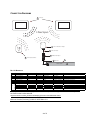
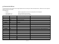
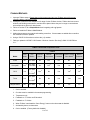
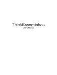
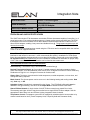
Integration Note
Manufacturer:
2GIG Technologies
Model Number(s):
CT30/CT100 Thermostats / Leviton VRC0P-1LW
(+3) RS-232 Adapter
Minimum Core Module Version:
g! 5.8
Document Revision Date:
12/30/2013
OVERVIEW AND SUPPORTED FEATURES
The 2GIG Technologies CT30 thermostats are wireless Z-Wave thermostats capable of controlling 1 or 2
stage heat pumps or conventional heating systems, a 2-stage cooling system and AUX heat. The CT30
thermostats are remote controllable over Z-Wave 900mhz wireless mesh networks via the use of a ZWave RS-232 adapter, enabling 2-way control and feedback from g!. The g! system supports up to 16
wireless thermostats.
Note: The CT100 thermostat has been tested using the CT30 driver and is compatible within the confines
of the CT30 driver supported features.
Note: Z-Wave RF operates at 900MHz. Any other devices operating on the same frequency may cause
interference and need to be removed. Leviton recommends the system in installations of 7500 square
feet or less and installing devices typically no more than 30 feet apart. Please refer to the Leviton Vizia
RF Systems Guide (www.ViziaRF.com) for other installation considerations and details on proper setup
of the Z-Wave networks. Additional information can be found at www.z-wave.com.
THE CT30 DRIVER SUPPORTS THE FOLLOWING FEATURES:
Auto Discovery: Thermostats may be auto-detected and added into g!
Decimal Temperature Control: g! Core module 5.5 added support for decimal temperature display.
2GIG Technologies’ CT30 thermostat set points can be set to .5 degree increments in Celsius mode only.
Feedback on the g! UI’s is in .5 degree increments for Celsius mode.
History View: The history view shows the inside temperature, outside temperature, unit run times, and
cooling and heating setpoints.
Mode Control: The climate system can be set to run in the following heating and cooling modes: Heat
only, Cool only, or Off.
Schedule Control: Scheduling is supported from the Viewer. The CT30 Built-in Schedule must be
disabled to use g! scheduling. Set the CT30 to Simple Mode to disable the Built-in Schedule.
Shared Z-Wave Network: A single Leviton Vizia RF Z-Wave network may contain Door Locks,
Thermostats, and Lights. All three may be controlled over a single RS-232 Z-Wave adapter. See the
appropriate Z-Wave Door Lock and Z-Wave Lighting Integration Notes for details.
Temperature Control: Temperature control can be managed by schedules tied to house modes or by
manual control based on time (Timed Temporary Hold, Temporary Hold and Permanent Hold).
ELAN Home Systems ● 1690 Corporate Circle ● Petaluma, CA 94954 USA
tech support: 800.622.3526 • main: 760.710.0990 • sales: 877.289.3526 • email: [email protected]
©2013 ELAN Home Systems. All rights reserved. ELAN and g! are trademarks of ELAN Home Systems. All other trademarks are the property of their respective owners.
THE CT30 DRIVER DOES NOT SUPPORT THE FOLLOWING FEATURES:
Name Detection: All thermostats will populate during auto-discovery with their Z-Wave node number as
their name. Thermostat names do not read into g! at this time.
Mode Control: CT30 thermostats do not support Auto mode.
Remote Sensors: CT30 thermostats do not support Remote Sensors.
Note: The “Save Energy” button on the front of the CT30 is disabled when Z-Wave control is enabled.
Any feature not specifically noted as “supported” is not supported.
INSTALLATION OVERVIEW
1. Install the CT30 thermostats and wire HVAC according to standard 2GIG Technologies
documentation.
Note: The 2GIG Technologies CT30 thermostats will run off battery power and support Z-Wave
beaming for incoming signals. However, when the C-Wire power connection is used they will also
actively help route Z-Wave messages. See the 2GIG Technologies Z-Wave USNAP Module User
Guide for details.
2. Test the thermostat and climate system to ensure that the thermostats correctly turn on the
appropriate heating or cooling equipment, and open or close the appropriate valves / dampers.
3. Install a Leviton VRC0P-1LW (+3) RS-232 Z-Wave adapter in a location convenient for both a serial
run to the g! Controller and within range of other Z-Wave devices.
Note: Be sure that the “+3” notation is present on the back of the VRC0P-1LW. (See the Leviton
application note for additional information: http://communities.leviton.com/docs/DOC-2392).
4. Run a Cat-5 or serial cable to the location of the Z-Wave RS-232 location.
5. Using a Primary Controller, such as a programming remote (ex. Leviton VRCPG), ControlThink’s
ThinkEssentials or Leviton’s Vizia RF+ Installer Tool (v1.1.0.0) create a Z-Wave network and add
thermostats and the RS-232 adapter according to standard procedures.
Note: CT30 thermostats do not provide unsolicited feedback so there is no need to “associate” them
to the VRC0P-1LW. The g! Controller polls them for data as needed.
Important! Disconnect the g! system from the VRC0P controller when any Z-Wave network
configuration is occurring.
6. Connect the Serial Cabling to the Z-Wave RS-232 adapter electrically. See the wiring diagrams.
7. Configure g! for the thermostats and confirm communication between the thermostats and the g!
Controller.
8. Test the system by changing the set points, modes and schedules on the viewer and various
thermostats, confirming that the various components in the system respond as expected.
Note: The CT30 has two modes of operation, Simple Mode and Normal Mode. When interfacing
with a g! system the CT30 should be set to Simple Mode. Failure to do this can cause incorrect /
confusing operation, particularly in regard to Scheduling features.
2 of 12
Z-WAVE REPEATERS
Many Z-Wave devices function as repeaters, meaning an incoming signal can be passed to another ZWave device within range. The maximum distance a signal can be sent from one Z-Wave device to
another varies depending on the brand/model of the device used. See the manufacturer’s
documentation for the devices you intend to use for specifics.
The signal can be extended from the controller to the device being controlled by a maximum of four
passes, known as “hops.” (From the controller to the first device, the first device to the second, the
second device to the third and from the third device to the one actually being sent the signal.)
Depending on the network configuration, occasionally it may be necessary to manually program the
“hops” to optimize reliability. Refer to the documentation that came with your specific programming
tool for details.
Note: Because Z-Wave door locks require repeaters that are “beaming-compatible” and that support
beaming of encrypted signals we recommend using only repeaters (lamp modules, switches, etc.) that
support these features if door locks will be a part of the installation. See the manufacturer’s
documentation for the devices you intend to use for specifics.
3 of 12
CONNECTION DIAGRAMS
1
Thermostats
Z-Wave Signals
2
3
DB9 to RJ11 Cable
4
7
Leviton Z-Wave RS-232 Adapter
DB9M to RJ45 Adapter
Z-Wave Repeating Module
5
RS-232 Port
Cat5 Cable
6
HC Controller
BILL OF MATERIALS
Device
1
2
3
4
5
6
7
8
Thermostat
Z‐Wave RS‐232Adapter
RJ‐11 to DB9 Cable
DB9 to RJ‐45 Adapter
Cat5 Cable Assembly
Controller
Z‐Wave Repeating Module
Programming Remote
OR
ControlThink's ThinkEssentials
OR
Vizia RF+ Installer Tool
Manufacturer
Part Number
Protocol
Connector Type
Notes
2GIG Technologies
Leviton
Leviton
ELAN
Installer
ELAN
Various
Leviton
CT30
VRC0P‐1LW (+3)
N/A
HA‐CB‐307
N/A
HCxx
Various
VRCPG‐BSG
Z‐Wave
RS‐232/Z‐Wave
RS‐232 RJ‐45 Female x DB9 Male
RS‐232
RS‐232
Z‐Wave
Z‐Wave
RF
RJ‐11 Female
RJ‐11 Male / DB9 Female Included w/ VRC0P+3
RJ‐45Male x RJ‐45 Male
RJ‐45 Female
RF
RF
Must terminate all 8 conductors
Use Comm port 1, 2, 3, etc.
Beaming and Encrypted Signal Support Recommended
Not Shown ‐ Needed to set up Z‐Wave Network
Leviton
CTZUS‐1US
Z‐Wave
RF
Not Shown ‐ Needed to set up Z‐Wave Network
Leviton
VRUSB‐1US
Z‐Wave
RF
Not Shown ‐ Needed to set up Z‐Wave Network
Note: Update the VRC0P-1LW (+3) to the latest firmware prior to creating the Z-Wave network. Updates
are found on the Leviton web site.
http://www.leviton.com/OA_HTML/SectionDisplay.jsp?section=42159&minisite=10251
Minimum Version: $Leviton(C) 2008 V2.33S/Z-Wave 3.11
4 of 12
Z-WAVE NETWORK PROGRAMMING
Program the Z-Wave according to standard procedures. Regardless of device function, the basic setup of
Z-Wave networks is the same. Various limitations may be imposed based on the programming tool used.
Refer to the documentation that came with your specific programming tool for details.
Typically a Z-Wave network is programmed using its Programmer/Remote Control (such as the Leviton
VRCPG-BSG remote, ThinkEssentials Software or Vizia RF+ Installer Tool) to enroll include devices in
the Z-Wave Network. The methods for using the VRCPG, ThinkEssentials and Vizia RF+ Installer Tool
are detailed below. Note that these instructions assume you are familiar with Z-Wave programming
concepts. If you require further detail or clarification, you may wish to see Leviton Vizia RF
(www.ViziaRF.com), or 2GIG Technologies documentation/technical support for assistance.
Important! Programming using the Leviton VRCPG-BSG Remote is NOT supported for
thermostats when Z-Wave locks are to be included in the system.
While the VRCPG-BSG does allow you to enroll locks in a Z-Wave network, it does not allow you to
associate the locks with the VRC0P module.
PROGRAMMING USING THE LEVITON VRCPG-BSG REMOTE:
Setup steps below are created using a VRCPG-BSG remote. Your steps may vary somewhat if your
remote model differs, but the basic process should be the same.
1. Confirm all devices are at factory default and have not been setup in any Z-Wave Network.
2. To include the CT30 thermostats in the network:
a. Start up the Leviton Remote and begin the Installation Checklist.
i.
Perform Step 1 of the Installation Checklist, Include Dimmers/Switches, and
include the first thermostat in the network.
ii.
When prompted by the remote, on the CT30 thermostat:
1. Press the Menu button.
2. Press the Mate button.
3. Press the Mate button. When the thermostat has been added to the network the
word LINK will appear under the radio tower icon of the thermostat, the
programming software will confirm the thermostat has been included in the
network and its icon will be displayed in the Design Tab. The software will
automatically assign a Node ID to each thermostat during this process.
Note: If you have two USNAP Modules installed in the CT30, select the radio you want to include
in the network. (Multiple radio options are shown in the upper left corner of the thermostat’s
display.) The selected radio (R1 or R2) will show in the center of the screen. Then press the
Mate button the second time.
Tip: It is best practice to give the thermostat a descriptive name when prompted, like Master
Bedroom, for future reference. Note that this name is not saved in the thermostat and will not be
automatically read into g! You should keep notes of the location of each thermostat and their
Node IDs, as the only identification available to g! is the Node ID.
3. Repeat Step 2 for each additional CT30 to be added to the network.
5 of 12
4. To include the VRC0P-1LW (+3) in the network:
b. Set the VRC0P-1LW to programming mode by pressing and holding the button (clear tab on
face of unit) until the light blinks amber.
c.
Perform Step 2 of the Installation Checklist, Include Controller, to include all Controllers into
the network. Controllers include the RS-232 interface module (VRC0P-1LW (+3)).
5. Perform Step 3 of the Installation Checklist, Update Controller, to update all of the controllers
following the inclusion of all devices. This will create the proper mapping between devices.
6. In a thermostat only network, you may skip Step 4 (Create Areas) and Step 5 (Set Associations)
of the Installation Checklist.
7. You may complete or skip Step 6 (Security) of the Installation Checklist as desired.
8. Choose Step 7 of the Installation Checklist, Install Complete.
9. Test all devices for proper operation. From the Main Menu of the VRCPG remote you should be
able to select Thermostats and get current temperature data and change modes (heat, cool etc)
for each thermostat on your network.
PROGRAMMING USING THINKESSENTIALS AND USB Z-WAVE ADAPTER:
Setup steps below are created from version 2.5 of ThinkEssentials. If you are running a different version,
your steps may be somewhat different than below, but the basic process is the same.
2. Confirm all devices are at factory default and have not been setup in any Z-Wave Network.
3. Either create a New Network or Open an Existing Network file.
4. To include the CT30 thermostats in the network:
a. In the ThinkEssentials software, select the Add Device button.
b. On the CT30 thermostat:
i.
Press the Menu button.
ii.
Press the Mate button.
iii.
Press the Mate button. When the thermostat has been added to the network the
word LINK will appear under the radio tower icon of the thermostat, the programming
software will confirm the thermostat has been included in the network and its icon will
be displayed in the Design Tab. The software will automatically assign a Node ID to
each thermostat during this process.
Note: If you have two USNAP Modules installed in the CT30, select the radio you want to include
in the network. (Multiple radio options are shown in the upper left corner of the thermostat’s
display.) The selected radio (R1 or R2) will show in the center of the screen. Then press the
Mate button the second time.
5. Repeat Step 3 for each additional CT30 to be added to the network.
6. To include the VRC0P-1LW in the network:
a. Set the VRC0P-1LW (+3) to programming mode by pressing and holding the button (clear
tab on face of unit) until the light blinks amber.
b. In the ThinkEssentials software, from the Design Tab select the Add Device button. The
software will confirm the VRC0P-1LW has been included in the network and its icon will be
displayed in the Design Tab. The software will automatically assign a Node ID during this
process.
Tip: It is best practice to give the thermostat a descriptive name when prompted, like Master
Bedroom, for future reference. Note that this name is not saved in the thermostat and will not be
automatically read into g! You should keep notes of the location of each thermostat and their
6 of 12
Node IDs, as the only identification available to g! is the Node ID.
7. Test all devices for proper operation. From the Design Tab you should be able to right-click on
each thermostat and choose Advanced Thermostat Options to see current temperature data
and change modes (heat, cool, etc.) for each thermostat on your network.
PROGRAMMING USING LEVITON’S VIZIA RF+ INSTALLER TOOL (V1.1.0.0) AND USB Z-WAVE ADAPTER:
Setup steps below are created from version 1.1.0.0 of the Vizia RF+ Installer Tool. If you are running a
different version, your steps may be somewhat different than below, but the basic process is the same.
1. Confirm all devices to be added are at factory default and have not been setup in any ZWave Network.
2. Either create a New Network or Open an Existing Network file.
3. To include the CT30 thermostats in the network:
a. In the Vizia RF+ software select the Include Device button.
b. On the CT30 thermostat:
i.
Press the Menu button.
ii.
Press the Mate button.
iii.
Press the Mate button. When the thermostat has been added to the network the
word LINK will appear under the radio tower icon of the thermostat and the
programming software will confirm the thermostat has been included in the network
and it will be displayed in the All Devices node of the programming tree. The
software will automatically assign a Node ID to each thermostat during this process.
Note: If you have two USNAP Modules installed in the CT30, select the radio you want to include
in the network. (Multiple radio options are shown in the upper left corner of the thermostat’s
display.) That radio (R1 or R2) will show in the center of the screen. Then press the Mate button
the second time.
4. Repeat Step 3 for each additional CT30 to be added to the network.
5. To include the VRC0P-1LW (+3) in the network:
c.
Set the VRC0P-1LW to programming mode by pressing and holding the button (clear tab on
face of unit) until the light blinks amber.
d. In the Vizia RF+ software select the Include Device button. The software will confirm the
VRC0P-1LW has been included in the network and it will be displayed in the All Devices
node of the programming tree. The software will automatically assign a Node ID during this
process.
Tip: It is best practice to give the thermostat a descriptive name when prompted, like Master
Bedroom, for future reference. Note that this name is not saved in the thermostat and will not be
automatically read into g! You should keep notes of the location of each thermostat and their
Node IDs, as the only identification available to g! is the Node ID.
6. Test all devices for proper operation. Select each thermostat from the All Devices node of the
programming tree and change modes (heat, cool, fan, etc.) for each thermostat on your network.
Note: Minimum and Maximum temperatures do not apply to the CT30 thermostats. They only
have one set point.
NOTES REGARDING THE TRACKING OF Z-WAVE DEVICES:
In general g! keeps track of the states of all of the Z-Wave Network Devices; however there is latency in
the reporting back of the devices from the Z-Wave network. The result is that g! updates its states as the
devices report back. This is evident when watching the viewer interface after a change is made at the
device. The viewer controls will update sequentially over a few seconds (or more on larger systems) as
the devices report their states.
7 of 12
g! CONFIGURATION DETAILS
The following table provides settings used in the g! Configurator when connecting to a Z-Wave thermostat network. Please refer to the Configurator
Reference Guide for more details.
In the table below:
o
“<Select>”
Select the appropriate item from the list (or drop-down) in the Configurator.
o
“<User Defined>”, etc.
Type in the desired name for the item.
o
“<Auto Detect>”, etc.
The system will auto detect this variable.
Devices
Communication Device
HVAC Units
Variable Name
Setting
Comments
Name
Type
Communication Type
Location
Comm Port
<User Defined> (Default: New Device)
Serial Port
Leviton Z‐Wave RS‐232 Network
<User Defined> (Not Required)
<Select>
Com 1, 2, 3 etc.
Name
Model
Controls Heat
Controls Cooling
Controls Fan
<User Defined>
Generic HVAC Unit
<Select from list>
<Select from list>
<Select from list>
Set to YES if controlling Heat
Set to YES if controlling Cooling
Set to YES if controlling Fan
Click the Discover Devices button on the Communication Device
<Discover Devices>
Thermostats
Schedules
Global Options
Name
Location
Comm Device
Thermostat #
Heating Unit
Cooling Unit
Discover Devices will set a Default name of "Z‐Wave Thermostat #1, #2", etc.
<User Defined> (Not Required)
<Auto Detect>
<Auto Detect>
<Select from list>
<Select from list>
Set up HVAC Schedules Under Each T‐Stat
Units
Temporary Hold Mode
Temporay Hold Default Time
Outside Temperature Sensor
Outside Humidity Sensor
<Select from list>
<Select from list>
<Select>
<Select from list>
<Select from list>
Fahrenheit or Celsius
Timed Hold or Hold until next schedule period
Choose Optional sensor if installed or choose internet
Choose Optional sensor if installed or choose internet
8 of 12
TESTING THE Z-WAVE SYSTEM
On occasion it may be necessary to test the Z-Wave system “outside” of the g! interface to verify
communication between the thermostats and the controller (the VRC0P-1LW). The following steps are
intended to provide a method to test the basic communication status of the Z-Wave network.
1. Complete your Z-Wave network set-up as described above, ensuring all thermostats and
controllers have been added to the network.
2. Connect a serial cable from your computer to the VRC0P-1LW’s RJ-11 to DB9 cable. Use a USB
to Serial adapter if required.
3. Set up a terminal program (ex: HyperTerminal) with the following settings:
a. 9600 baud; 8 data bits; No parity; 1 stop bit; Flow Control – None
b. ASCII Sending Set Up
i. Send line ends with line feeds
ii. Echo typed characters locally
4. Send test commands to verify correct operation:
Note: Terminal programs other than HyperTerminal may display differently. The important thing
is that the “<E000” displays, indicating a correctly formatted command was entered. The “<X000”
indicates that the VRC0P module communicated correctly with the thermostat.
a. To set a thermostat to OFF:
i. In HyperTerminal type: >NxSE64,1,0 where “x” is the Node ID of the thermostat
being controlled and press Enter.
1. Feedback in HyperTerminal should be <E000 followed on the next line
by <X000 and then <E000 on the third line.
2. The selected thermostat shows that it is OFF.
b. To set a thermostat to HEAT:
i. In HyperTerminal type: >NxSE64,1,1 where “x” is the Node ID of the thermostat
being controlled and press Enter.
1. Feedback in HyperTerminal should be <E000 followed on the next line
by <X000 and then <E000 on the third line.
2. The selected thermostat shows that it is set to HEAT.
c.
To set a thermostat to COOL:
i. In HyperTerminal type: >NxSE64,1,2 where “x” is the Node ID of the thermostat
being controlled and press Enter.
1. Feedback in HyperTerminal should be <E000 followed on the next line
by <X000 and then <E000 on the third line.
2. The selected thermostat shows that it is set to COOL.
9 of 12
d. To query the STATUS of a thermostat:
i. In HyperTerminal type: >NxSE64,2 where “x” is the Node ID of the thermostat
being controlled.
1. Feedback in HyperTerminal should be <E000 followed on the next line
by <X000 and then <E000 on the third line. The fourth line should be
Nxxx:064,003,yyy where “xxx” is the Node ID of the thermostat (single
and double digit Node IDs will have leading zeros) and “yyy” is the status
of the thermostat.
a. 000 = OFF
b. 001 = HEAT
c.
002 = COOL
If you receive feedback where E000 (as noted above) is something different it indicates that the
command was not entered correctly.
If you receive feedback where X000 (as noted above) is something different it indicates that the VRC0P is
not communicating correctly with the thermostat.
Correct any problems prior to integrating with the g! system. Contact the manufacturer(s) of the
product(s) you are installing for additional help with troubleshooting your Z-Wave network.
10 of 12
COMMON MISTAKES
1. Improper Z-Wave setup. Ensure that you fully program and test your Z-Wave network for proper
operation prior to integration with g!
2. Placing the Z-Wave RS-232 Adapter out of range of other Z-Wave devices. Z-Wave devices create a
wireless, self-healing mesh network, and should be placed where they are in range to communicate
with multiple other devices for best results.
3. Failure to set the CT30 to Simple Mode when integrating with a g! system.
4. Failure to install the Z-Wave USNAP Module.
5. Adding thermostats to the network after adding controllers. If thermostats are added after controllers
the controllers must be updated.
6. Using a VRC0P-1LW that does not have the (+3) notation.
7. Failing to update the VRC0P-1LW firmware. Minimum Version: $Leviton(C) 2008 V2.33S/Z-Wave
3.11.
Z-Wave Thermostat Comparison Chart
Feature
Model
Auto
Mode
Fan
Modes
Remote
Sensor
Decimal
Temperature
Unsolicited
Feedback
Green / Energy
Save Mode*
Built-In
Schedule
2GIG
No
On / Auto
No
Yes4
No
No6
Yes8
Honeywell
Yes1
On / Auto
/ Circulate
No
Yes5
Yes
No
Yes8
RCS
Yes
On / Auto
/
Circulate2
Yes3
No
Yes
Yes7
Yes9
Trane
Yes
On / Auto
/
Circulate2
No
No
Yes
Yes7
Yes8
Wayne Dalton
No
On / Auto
No
No
No
Yes7
No
1. Can be enabled.
2. Circulate must be enabled in thermostat programming.
3. Temperature only.
4. Feedback to .5° Celsius and Fahrenheit.
5. Feedback to .5° Celsius.
6. When Z-Wave is activated the “Save Energy” button on the thermostat is disabled.
7. Activated by button on thermostat.
8. Can be enabled. (Factory default is disabled.)
11 of 12
9. Can be disabled. (Factory default is enabled.)
12 of 12