1
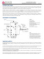
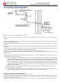
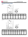
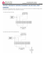
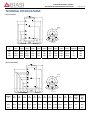
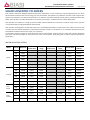
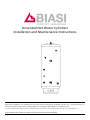
 Unvented Hot Water Cylinders Installation and Maintenance Instructions IMPORTANT NOTE TO THE INSTALLER Read these installation and maintenance instructions before commencing. Unvented cylinders are a controlled service as defined in the latest edition of the building regulations and should only be fitted by a competent person. The relevant regulations are: England and Wales – Building Regulation G3; Scotland – Technical Standard P3; North Ireland – Building Regulation P5. After installation the installer must left the instructions manual with the householder. unvented hot water cylinders installation and maintenance instructions Page 2 / 20
PRE‐INSTALLATION STORAGE Store the unit standing upright in its original packaging in an area free from excessive damp. FEATURES OF THE UNVENTED CYLINDER: ‐ Made from Duplex Stainless Steel for excellent corrosion resistance ‐ Strong rust‐proofed steel case ‐ Highly insulated with environmentally friendly foam ‐ Available in range of sizes to suit ‐ 125L, 150L, 170L, 200L, 250L and 300 litres ‐ All models including Solar models are available in Direct or Indirect versions ‐ Supplied complete with all the necessary safety and control devices needed to connect cold water mains ‐ All safety and control devices are pre‐adjusted ‐ High quality controls selected that combine high flow rate performance with minimum pressure drop which gives fantastic performance in all areas, with great improvements in areas with poor water pressure ‐ KIWA approved for compliance with the Water Supply (Water Fittings) Regulations 1999 and Building Regulations G3 & L. COMES COMPLETE WITH ALL THE FITTINGS YOU NEED TO COMPLETE THE INSTALLATION: ACCESSORIES Expansion Vessel Wall mounting kit for expansion vessel Expansion vessel hose Tundish 10 way electrical box High flow rate inlet control set Two port valve Immersion heater Temp & Pressure relief valve Dual thermostat High limit stat Installation & Maintenance Instructions DIRECT INDIRECT 3
3
3
3
2
3
2
3
3
2
2
3
3
3
3
3
3
3
3
3
3
3
2
3
SOLAR DIRECT SOLAR INDIRECT
3 3 3 3 3 3 3 3 3 2 3 3 3
3
3
3
3
3
3
3
3
3
3
3
Storage capacity 150L 170L 200L Operating pressure 5,5 bar Max Water supply pressure 10 bar Max Primary working pressure 3 bar Pressure reducing valve 3 bar Immersion heater Expansion vessel charge pressure 125L 3kW / 240V, 1¾’’, 16’’ LONG 3 bar 250L 300L unvented hot water cylinders installation and maintenance instructions Page 3 / 20
SITING THE UNIT This unit can supply outlets above it or at some distance from it but any outlets above the unit will reduce the available outlet pressure by 0.1 bar for every 1m of height difference. The maximum length of the “dead leg” should be as stated in the Water Supply (Water Fittings) Regulations 1999 G18.7, in particular to the area of most frequent use. Particular attention is needed if sitting in a garage or outbuilding as the unit should be protected from frost. All exposed pipework must be insulated. The unit must be installed UPRIGHT on a flat base capable of supporting its weight when full (please see the technical specification section for weights). The minimum recommended cupboard size is 650mm square. Sufficient access to allow maintenance of the valves should be considered. In addition the immersion heaters are 400mm in length and this distance should be considered to allow withdrawal for servicing if required. The discharge pipework from the safety valves should fall continuously and terminate safely. SCHEMATIC DIAGRAM Legend: 1. Bronze Pump 2. Non Return Valve 3. Two Port Valve 4. Temperature & Pressure Relief Valve 5. Expansion Relief Valve 6. Expansion Vessel with wall bracket 7. Pressure Reducing Valve 8. Isolating Valve 9. Drain Valve (not supplied) SECONDARY
FLOW
4
SECONDARY RETURN CIRCUIT
(200, 250 & 300 LITER SIZES)
6
5
1
2
FLEXIBLE HOSE
3
COLD
MAIN
2
PRIMARY
FLOW
8
BALANCED COLD
CONNECTION
DUAL
STAT
PRIMARY
RETURN
COLD FEED
9
7
Note: The pressure reducing valve, non‐return valve and expansion relief valve are combined together in the inlet control et. On 125‐170L sizes there is no dedicated secondary return boss and the secondary return circuit should be tee’d into the cool feed pipe just above the drain elbow.
WATER SUPPLY The performance of any unvented system is only as good as the mains water supply available. To this effect the maximum possible water demand should be assessed, with the knowledge that the mains supplies both hot and cold services simultaneously. The water heater itself operates at a pressure of 3 bar, controlled by the inlet control set, and is capable of delivering over 50 litres per minute. The high quality inlet control set has been designed to make the most of the flow rates available. The water supply should be checked to ensure it can meet these requirements. If necessary, consult the local water authority regarding the likely pressure and flow rate availability. Consideration should be given to upgrading existing ½” (15mm) cold mains pipework to a larger size if the recommended minimum pressure/flow rate is not being achieved. Note: A high static (no flow) mains pressure is no guarantee of good flow availability. In a domestic installation 1.5 bar and 25 l/min. should be regarded as the minimum. The maximum mains pressure that the inlet control set can cope with is 10 bar.
unvented hot water cylinders installation and maintenance instructions Page 4 / 20
GENERAL INSTALLATION CONNECTING TO THE CYLINDER All of the pipework connections on the cylinder are 22mm compression and supplied complete with gland nuts and olives, in the Accessory Kit box. Only connect 22mm Table X copper tube to these connections. Cut the tube with a pipe cutter and ensure no sharp edges or burrs protrude. Slide both gland nut and olive onto the tube and push tube fully home into the connection, ensuring the tube end fully bottoms on the connection recess. Smear the outer wall of the olive with plumbing paste and tighten gland nut correctly. Upon filling / commissioning, ensure all connections are completely watertight. Note: No control or isolation valve should be fitted between the expansion relief valve and the storage cylinder. The relief valve connections should not be used for any other purpose. COLD MAINS PIPEWORK Run the cold main through the building to the place where is to be installed. Take care not to run the cold pipe near hot water or heating pipe work so that the heat pick‐up is minimized. Identify the cold water supply pipe and fit an isolating valve (not supplied). A 22mm BS1010 stopcock can typically be used but a 22mm quarter turn full bore valve would be better as it does not restrict the flow as much. Do not use “screwdriver slot” or similar valves. Make the connection to the cold feed of the cylinder and incorporate a drain valve. Position the inlet control just ABOVE the Temperature & Pressure Relief Valve (TPRV) mounted on the side of the cylinder. This ensures that the cylinder does not have to be drained down in order to service the inlet control set. Ensure that the arrow points in the direction of the water flow. Select a suitable position for the expansion vessel. Mount it to the wall using the bracket provided. Use the flexible hose provided to connect to the inlet control group. BALANCED COLD CONNECTION If there are to be showers, bidets or monobloc taps in the installation then a balanced cold supply is necessary. There is a 22mm balanced connection on the inlet control set. HOT WATER PIPEWORK Run the first part of the hot water distribution pipework in 22mm. This can be reduced to 15mm and 10mm as appropriate for the type of tap etc. Your aim should be to reduce the volume of the hot draw‐off pipework to a practical minimum so that the time taken for the hot water is as quick as possible. Do not use monobloc mixer tap or showers if the balanced cold connection is not provided. Outlets of this type can back pressurize the unit and result in discharge. Select a suitable position for the expansion vessel. Mount it to the wall using the bracket provided and connect to the inlet control set with the flexible hose provided. Ensure that the top of the vessel is accessible for servicing. PRIMARY COIL CONNECTIONS Connect the primary connections (Indirect only) using the compression connections provided. The primary circuit must be positively pumped. Gravity circulation is not suitable. Either primary connection may be used as the primary flow. Reheat times are identical either way. The primary circuit can be open vented or sealed, with up to a maximum pressure of 3.5 bar. If you seal the primary circuit an additional expansion vessel and safety valve is required. The boiler may be Gas, Electric or Oil but must be under effective thermostatic control. Uncontrolled heat sources such as some AGA’s, back boilers, solid fuel stoves, etc. are NOT SUITABLE. Please contact our Technical department for guidance. Connect the two port zone valve (indirect only) into the primary flow pipework. The direction of flow arrow should be towards the primary flow connection. On twin coil solar cylinders we have provided an extra thermostat boss should you wish to use it. Again a two port zone valve should be fitted (supplied). SECONDARY CIRCULATION Can be used with secondary circulation. An appropriate WRAS approved bronze circulator should be used in conjunction with a non‐return valve to prevent backflow. On large secondary circulation systems it may be necessary to incorporate an extra expansion vessel into the circuit to accommodate the increased system water volume. Secondary circulation should be avoided on Direct electrically heated units being used on off‐peak electricity tariffs. A secondary return boss is fitted as standard on 200L, 250L and 300L units. On smaller sizes, tee into the cold feed pipe above the drain. IMMERSION HEATERS Only immersion heaters with a thermal cutout may be used. To help ensure this, the immersion heaters have a special 1¾” thread. They are rated at 3 kW at 240 V and are of a low noise Incoloy construction. They have both a thermostat and a high limit cutout. Please order the correct replacement from BIASI; fitting non‐approved immersions may affect your guarantee. When fitting, ensure the ‘O’ ring is positioned correctly on the head of the immersion heater and lubricate before fitting. Fit it by hand until almost home then tighten gently as the ‘O’ rings will seal easily. The electrical supply to each immersion heater must be fused at 13A via a double pole isolating switch to BS 3456. The cable must be 2.5mm2 heat resistant (85°C HOFR) sheathed flex complying to BS 6141:1981 Table 8. Do not operate the immersion heater/s until the unit is full of water. Do not operate the immersion heater/s if any sterilisation liquid is in the cylinder as this will cause premature failure. Fit the immersion thermostat (indirect units only) into the thermostat pocket. Complete the wiring – use the appropriate wiring diagrams. unvented hot water cylinders installation and maintenance instructions Page 5 / 20
DISCHARGE ARRANGEMENT Note: It is not acceptable to discharge straight into a soil pipe Note: The discharge will consist of scalding water and steam. Asphalt, roofing felt and non‐metallic rainwater goods may be damaged by such discharges. The inlet control group should be positioned so that the discharge from both safety valves can be combined via a 15mm end feed Tee, as in the diagram above. Connect the tundish and route the discharge pipe which must be routed in accordance with Building regulation ‐ Part G3 of schedule 1. When operating normally water will not be discharged. Water discharge from the two safety valves will only occur under fault conditions. The tundish should be vertical, located in the same space as the unvented hot water storage system and be fitted as close as possible, within 500mm of the safety device e.g. the temperature relief valve. The position of the tundish must be that when installed it is visible to the occupants of the premises. When positioning the tundish, the drain valves and motorised valve ensure that these items are positioned away from any electrical devices. The discharge pipe (D2) coming from the tundish should terminate in a safe place where there is no risk to persons in the vicinity of the discharge, be of metal and: A) Be at least one pipe size larger than the nominal outlet size of the safety device unless its total equivalent hydraulic resistance exceeds that of a straight pipe 9m long, i.e. discharge pipes between 9m and 18m equivalent resistance length should be at least two sizes larger than the nominal outlet size of the safety device, between 18 and 27m at least 3 sizes larger, and so on. Bends must be taken into account in calculating the flow resistance. Refer to diagram 1, Table 1 and the worked example. An alternative approach for sizing discharge pipes would be to follow BS6700 Specification for design, installation, testing and maintenance of services supplying water for domestic use within buildings and their curtilages. B) Have a vertical section of pipe at least 300mm long, below the tundish before any elbows or bends in the pipework. C) Be installed with a continuous fall. D) It is preferable for the discharge to be visible at both the tundish and the final point of discharge. Where this is not possible or practically difficult, there should be clear visibility at one or other of these locations. Examples of acceptable discharge arrangements are: 1. Ideally below the fixed grating and above the water seal in a trapped gulley. 2. Downward discharges at a low level; i.e. up to 100mm above external surfaces such as car parks, hard standings, grassed areas etc. are acceptable providing that where children play or otherwise come into contact with discharges, a wire cage or similar guard is positioned to prevent contact whilst maintaining visibility. 3. Discharges at a high level; e.g. in to metal hopper and metal down pipe with the end of the discharge pipe clearly visible (tundish visible or unvented hot water cylinders installation and maintenance instructions Page 6 / 20
not) or onto a roof capable of withstanding high temperature discharges of water and 3m from any plastic guttering systems that would collect such discharges (tundish available). 4. Where a single pipe serves a number of discharges, such as in blocks of flats, the number served should be limited to not more than 6 systems so that any installation can be traced reasonably easily. The single common discharge pipe should be at least one pipe size larger than the largest individual discharge pipe to be connected. If unvented hot water storage systems are installed where discharges from safety devices may not be apparent, i.e. in dwellings occupied by blind, infirm or disabled people, consideration should be given to the installation of an electronically operated device to warn when discharge takes place. WORKED EXAMPLE The example below is for G1/2 temperature relief valve with a discharge pipe (D2) having 4 No. elbows and length of 7m from the tundish to the point of discharge. From Table 1: Maximum resistance allowed for a straight length of 22mm copper discharge pipe (D2) from a G1/2 temperature relief valve is: 9.0m. Subtract the resistance for 4 No. 22mm elbows at 0.8m each = 3.2m. Therefore the maximum permitted length equates to: 5.8m. 5.8m is less than the actual length of 7m, therefore calculate the next largest size. Maximum resistance allowed for a straight length of 28mm pipe (D2) from a G1/2 temperature relief valve equates to: 14m. As the actual length is 7m, a 28mm (D2) copper pipe will be satisfactory. Table1 ‐ Sizing of copper discharge pipe (D2) for a temperature relief valve with a G1/2 outlet size (as supplied). Size of discharge pipework Maximum length of straight pipe (no bends or elbows) Deduct the figure below from the maximum length for each bend or elbow in the discharge pipe 22mm Up to 9m 0.8m 28mm Up to 18m 1m 35mm Up to 27m 1.4m unvented hot water cylinders installation and maintenance instructions Page 7 / 20
TYPICAL WIRING DIAGRAMS These diagrams relate only to the components listed. Others may vary in their wiring requirements, particularly thermostats. Always refer to manufacturers’ instructions which may override the detail in order to function correctly. WIRING DIAGRAM 2 x TWO PORT ZONE VALVES (S‐
PLAN) VARIANT DUAL THERMOSTAT WIRING Zone Valve (Htg)
G
Br
RMT 230
Bl
1
Zone Valve (Dhw)
Room Stat
HP22
O
1
2
Room Stat
Cylinder Stat
RMT 230
ITD Dual Stat
HP22
4
2
WIRING DIAGRAM THREE PORT MID POSITION VALVE (Y‐PLAN) + TWO PORT VALVE VARIANT DUAL THERMOSTAT WIRING G
2
Br
Bl
1
1
O
2
IDT
Dual Stat
Control
2
1
C
4
2
Mid Position Valve
HP22
1
W
G
O
2
BI
G/Y
2
3
High Limit Stat
C
IDT Dual Stat
C
Power
Supply
E
Power
Supply
E
2
N
C
N
L
Unit
High Limit
Stat
L
1
1
3
2
5
4
6
8
7
9
2
2
3
4
5
6
7
8
9
10
10
BR
BL
G
2
1
Junction Box
HP22
Junction Box
1
2
3
2
1
3
2
3
N
NOT
USED
L
N
E
3
Htg Dhw
on
on
FP75 or CP15 Programmer
L
L
N
N
E
L
2
N
E
L
E
3
Pump
Basic Boiler
2
3
L
N
E
L
N
E
L
L
4
O
N
E
4
3
1
Htg Dhw Dhw
on
on off
FP75 or CP15 Programmer
2
N
E
3
Basic Boiler
Pump
COMMISSIONING FILLING First you must ensure that the pressure in the expansion vessel is the same as the setting of the pressure reducing valve i.e. 3 bar (45PSI). The valve is of the Schrader car tyre type. Check all the connections for water tightness including any factory made connections such as the immersion heater and the temperature and pressure relief valve. Prior to filling, open the hot tap furthest away from the BIASI SILVER to expel air. Open the cold main isolation valve and allow the unit to fill. Once the cylinder as been fully commissioned should be heated to its normal operating temperature. Draw off secondary hot water to each outlet and allow hot water to flow from each outlet for at least 30 seconds to remove any flux residue from the pipe work within the secondary hot water system. Then fully drain the cylinder and re‐filled to ensure that all flux residues is removed from the system. DIRECT UNITS After both filling with water and purging of sterilisation liquid, switch on the power to the immersion heaters and allow the unit to start to heat. The immersion heater is supplied preset at 55°C. Turning fully to + sets to approx 65°C. INDIRECT UNITS Fill the primary circuit according to the boiler manufacturers’ commissioning instructions. Ensure the lever on the two port valve is set to the filling position. When full, move the lever back. Switch the programmer to Domestic Hot Water (DHW) and allow the unit to start to heat. Adjust the dial of the dual thermostat to between 30°C and 70°C as required. STORAGE TEMPERATURE 60‐65°C is the recommended storage temperature for both direct and indirect cylinders. In hard water areas consideration should be given to reducing this to 50‐55°C. In many healthcare applications the guidance on Legionella control and safe water delivery temperatures will require storing the water at 60‐65°C, distributing at 50‐ 55°C and using thermostatic mixing valves to control the final temperature. For details consult the NHS Estates Guidance on safe hot water temperatures. unvented hot water cylinders installation and maintenance instructions Page 8 / 20
SAFETY VALVE CHECKS Any sign of water coming from either the expansion relief valve or the temperature/pressure relief valve during heat‐up indicates a problem. Next hold both of these safety valves fully open, allowing as much water as possible to flow through the tundish. Check that your discharge pipework is free from debris and is carrying the water away to waste efficiently. Release the valves and check that they reseat properly. SERVICING GENERAL Servicing should only be carried out by competent installers and any spare parts used must be purchased from BIASI Cylinders. NEVER bypass any safety devices or operate the unit without them being fully operational. DRAINING Switch the electrical power off (important to avoid damage to element). Isolate boiler from the unit. Turn off the cold water supply valve. Open hot water tap. Open the drain valve. The unit will drain. WARNING: WATER DRAINED OFF MAY BE VERY HOT! ANNUAL MAINTENANCE The water heaters require annual servicing in order to ensure safe working and optimum performance. It is essential that the following checks are performed by a competent installer on an annual basis. This is commonly done at the same time as the annual boiler service. 1) Twist the cap of the expansion relief valve on the inlet control set and allow water to flow for 5 seconds. Release and make sure it resets correctly. Repeat with the pressure / temperature relief valve. In both cases check that the discharge pipework is carrying the water away adequately. If not, check for blockages etc. and clear. WARNING: THE WATER DISCHARGED MAY BE VERY HOT! 2) Check that any immersion heaters fitted are working correctly and that they are controlling the water at a temperature between 55°C and 65°C. 3) Check the pressure in the expansion vessel is charged to 3 bar. Turn off the water supply to the unit and open a hot tap first. The air valve on expansion vessel is a Schrader (car tyre) type. Air or CO2 may be used to charge the expansion vessel. 4) Unscrew the head on the inlet control set and clean the mesh filter within. 5) The Benchmark Log Book supplied with this unit should be updated at each service. YOUR GUARANTEE MAY BE VOID WITHOUT PROOF OF ANNUAL SERVICING SPARE PARTS A full range of spare parts is available. unvented hot water cylinders installation and maintenance instructions Page 9 / 20
FAULT POSSIBLE CAUSE SOLUTION Water escaping from the case unit Compression fitting on hot – draw off not sealing Check/remake joint sealing paste Direct – immersion heater not switched on or cutout has triggered Check / reset Indirect – boiler not working Check boiler – consult boiler manufactures’ instructions Indirect – motorized valve fault Check plumbing / wiring motorized valve Indirect – cutout in dual stat has operated Reset and investigate cause If continual – pressure reducing valve (part of inlet control set) may not be operating correctly Check outlet pressure from inlet control set is 3bar If continual – expansion relief valve seat may be damaged Remove cartridge – check seat and renew if necessary If intermittent – expansion vessel charge may have reduced / bladder perished Check pressure in expansion vessel. Recharge to 3bar if necessary. If bladder perished replace vessel Unit it being back pressurized With cylinder cold check pressure in cylinder. If this is the same as the incoming mains pressure then you are getting backfeed. Install a balanced cold supply Water discharges from temperature & pressure relief valve Unit has overheated – thermal controls have failed Switched off power to boiler and immersion heaters. Leave water supply on. Wait until discharges stops. Isolate water supply and replace if faulty. Milky / cloudy water Oxygenated water Water from any pressurized system will release oxygen bubbles when flowing. The bubbles will settle out. Cold main off Check and open stopcock Stainer blocked in pressure reducing valve Isolate water supply and clean Inlet control set may be fitted incorrectly Check and refit required Noise during hot water draw off – typically worse in the morning Loose airing cupboard pipework Install extra clips Hot or warm water from cold tap If tap runs cold after a minute or so the pipe is picking up heat from heating pipework Insulate / re‐route Cold water at hot taps Water discharges from expansion relief valve No hot water flow GUARANTEE The stainless steel vessel carries a fully EXCLUSIONS – THE GUARANTEE DOES NOT COVER: transferable 25‐year guarantee against faulty materials or manufacture provided that: ‐ It has been correctly installed as per the Installation. Instructions and all the relevant standards, regulations and codes of practice in force at the time. ‐ It has not been modified in any way, other than by BIASI. ‐ It has not been misused, tampered with or subjected to neglect. ‐ The system is fed from the public mains water supply. ‐ It has only been used for the storage of potable water. ‐ It has not been subjected to frost damage. ‐ The unit has been serviced annually. ‐ The Benchmark Log Book has been filled in after each annual service. ‐ The guarantee period starts from the date of purchase and no registration is required. Please note that invoices for servicing may be requested to prove that the unit has been serviced annually The expansion vessel and cold water controls supplied with BIASI models carry a 2‐year guarantee. All other components fitted to/or supplied with the unit carry a 2‐year guarantee. unvented hot water cylinders installation and maintenance instructions Page 10 / 20
EXCLUSIONS – THE GUARANTEE DOES NOT COVER: ‐
‐
‐
The effects of scale build up. Any labour charges associated with replacing the unit or its parts. Any consequential losses caused by the failure or malfunction of the unit. GUIDANCE IN THE EVENT OF A PROBLEM If you have a problem in the first year, contact the plumber who fitted the unit. Thereafter contact the plumber who carries out the annual servicing for you. If your BIASI Silver develops a leak we will supply you with a new one. We ask for a nominal upfront payment to prevent fraud. We will require the original unit to be returned to us for inspection along with a copy of your Benchmark Log Book. If it is confirmed that it has failed within the terms of the guarantee your upfront payment will be refunded. If a component part fails within the guarantee period, we will send you a new one without any upfront charge. Credit card details may be taken to prevent fraud. We ask you to post the faulty part back to us within one month by recorded delivery. If you do not return the part we will charge you for it and for the postage and packing. If your part fails after the guarantee period, we will ask for upfront payment. USER INSTRUCTIONS Your stainless system is automatic in normal use and requires only annual servicing. You should employ a competent installer to perform the annual servicing. Normally this is timed to coincide with the annual boiler service. IF WATER IS FLOWING FROM THE SAFETY VALVES THROUGH THE TUNDISH THIS INDICATES A FAULT CONDITION AND ACTION IS NEEDED. If this water is hot, turn the boiler and / or the immersion heater off. Do not turn off the water until the discharge runs cool. The discharge may also stop. CALL OUT A COMPETENT PLUMBER TO SERVICE THE UNIT. Tell them you have a fault on an unvented cylinder. We stock all the spare parts they may need. unvented hot water cylinders installation and maintenance instructions Page 11 / 20
TECHNICAL SPECIFICATIONS DIRECT 35°
45°
A
B
C
D
F
E
Ø540
35°
45°
Top view
CAPACITY [L] A [mm] B [mm] C [mm] D [mm] E [mm] F [mm] WEIGHT Empty [kg] WEIGHT Full [kg] 125 150 170 200 250 300 1045 1205 1325 1505 1825 2105 812 972 1092 1272 1592 1872 647 757 837 957 1167 1242 287 287 287 287 287 287 272 272 272 272 272 272 ‐ ‐ ‐ 1042 1427 1667 30 34 37 41 49 56 155 184 207 241 299 356 INDIRECT 35°
45°
A
B
C
D
E
F
G
I
H
Ø540
35°
45°
Top view
CAPACITY [L] A [mm] B [mm] C [mm] D [mm] E [mm] F [mm] G [mm] H [mm] I [mm] WEIGHT Empty [kg]
WEIGHT Full [kg] 125 150 170 200 250 300 1045 1205 1325 1505 1825 2105 812 972 1092 1272 1592 1872 ‐ ‐ ‐ 957 1167 1242 340 340 327 327 350 350 272 272 272 272 272 272 290 290 290 290 290 290 420 420 490 490 525 525 615 615 690 690 760 760 ‐ ‐ ‐ 1042 1427 1667 35 39 43 47 57 64 158 187 210 244 303 360 unvented hot water cylinders installation and maintenance instructions Page 12 / 20
SOLAR UNVENTED DIRECT SINGLE COIL CYLINDER Detail for the installation of a Solar Unvented Direct cylinder in an electric home. GENERAL When installing this product it is essential the overall installation meets all current legislation including, in particular, the high limit isolation requirements of Building Regulation G3. This document is designed to assist in achieving that aim. WATER The potable water connection and tundish discharge connection are to be connected in exactly the manner described in Pages 3 to 7 of this manual. IMMERSION HEATERS The standard issue immersion heaters are designed for domestic usage where the lower heater is connected to a low rate off‐
peak tariff and the upper heater used for occasional top‐up purposes. Heaters of this nature are not designed to be permanently live. For usage outside of domestic parameters Titanium immersion elements are recommended. SOLAR CONNECTIONS The flow and return from the solar heat source are to be connected to the indirect coil. Either primary coil connection (A) may be utilised as the flow or return. The solar sensor, supplied as part of the solar controls, inserts into Pocket B and is held in‐situ with the black sensor pocket retaining bung provided. It is necessary to mount the solar pump in the return pipework with the RWC / ORKLI two port valve (supplied with the cylinder) installed between the cylinder and the pump. This valve is of the powered open, sprung closed design and is wired through the Imit ITL100 high limit stat which inserts into Pocket F. Two wiring options for high limit isolation are provided in Fig. 1 and Fig. 2. The superior option is Fig. 2 which disconnects the pump movement as well as provides valve closure (see pages 13 and 14). SOLAR UNVENTED INDIRECT TWIN COIL CYLINDER With either format it is essential the overall installation meets all current legislation including, in particular, the high limit isolation requirements of Building Regulation G3. This document is designed to assist in achieving this aim. UPPER COIL The upper coil is connected to the fossil fuel (not solid fossil fuel e.g. wood burner or coal) boiler as per the instructions for the Unvented Indirect single coil model with the limit TLSC control and high limit thermostat inserted into pocket I (lower diagram page 14). The wiring requirements are as depicted on page 13. LOWER COIL: SOLAR INSTALLATION In a solar powered system the lower coil is connected to the solar heat source. Either primary coil connection may be utilised as the flow or return. The solar cylinder sensor, supplied as part of the solar controls, inserts into pocket F (see page 14). It is necessary to mount the solar pump in the return pipework with the RWC / ORKLI two port valve (supplied with the cylinder) installed between the cylinder and the pump. This valve is of the powered open, sprung closed design and is wired through the Imit ITL100 high limit stat which inserts into pocket L (lower diagram page 14). Two wiring options for high limit isolation are provided in Fig. 1 and Fig. 2 page 13. The lmit ITC100 control thermostat is not required in a solar installation. LOWER COIL: TWO BOILER INSTALLATION Where the lower coil is to be used with a fossil fuel (not solid fossil fuel e.g. wood burner or coal) boiler, the pipework requirements are as per that of a Indirect single coil cylinder described earlier in this book. Electrically the Imit ITC100 inserts into Pocket F (see page 14) to control the boiler input and the Imit ITL100 limit stat into Pocket L (lower diagram page 14). The RWC / ORKLI two port valve may be installed into either the flow or return pipework. Wiring of the ITC100 and ITL100 are as per the wiring detail using the Imit TLSC on page 7. unvented hot water cylinders installation and maintenance instructions Page 13 / 20
TYPICAL SCHEMATIC WIRING DIAGRAM: SOLAR HIGH LIMIT CONTROL These schematic wiring diagrams depict an IMIT high limit control stat and the connections are numbered accordingly. Where an alternative is supplied connect as per manufacturers’ instructions. unvented hot water cylinders installation and maintenance instructions Page 14 / 20
TECHNICAL SPECIFICATIONS SOLAR DIRECT 35°
45°
A
B
C
D
E
F
G
I
H
J
Ø 540
35°
45°
Top view
CAPACITY [L] A [mm] B [mm] C [mm] D [mm] E [mm] F [mm] G [mm] H [mm] I [mm] J [mm] WEIGHT Empty [kg]
WEIGHT Full [kg] 200 1505 1272 957 327 272 290 490 690 1042 1254 47 244 250 1825 1592 1167 350 272 290 525 760 1427 1574 57 303 300 2105 1872 1242 350 272 290 525 760 1667 1854 64 360 SOLAR INDIRECT 35°
45°
A
B
C
D
E
F
G
H
I
J
L
K
Ø 540
35°
45°
Top view
CAPACITY A [L] [mm] WEIGHT
Empty [kg] WEIGHT
Full [kg] 1115 1254 51 246 1427
1332 1574 63 306 1667
1472 1854 70 363 B [mm] C [mm] D [mm] E [mm] F [mm] G [mm] H [mm] I [mm] J [mm] K [mm] 200 1505 1272 740 272 290 490 690 790 955 1042
250 1825 1592 882 272 290 525 760 932 1097
300 2105 1872 740 272 290 525 760 1072
1237
L [mm] unvented hot water cylinders installation and maintenance instructions Page 15 / 20
SOLAR UNVENTED CYLINDERS Solar cylinders have been designed specifically with Solar applications in mind. Featuring a purpose designed solar coil, which allows maximum heat transfer of solar energy into the stored water, the cylinders are suitable for use with a wide range of solar systems now available in the UK and Ireland and are an efficient and environmentally friendly way of providing Domestic Hot Water. Solar cylinders also offer the benefit of mains pressure hot water – powerful showers and fast filling baths. Solar cylinders are available in a range of sizes from 200L, 250L and 300 litres and in Direct or Indirect versions. Solar cylinders are manufactured from high grade Duplex stainless steel.
Solar cylinders are designed to accept heat input from a renewable/sustainable (i.e. Solar) heat source. Where this input does not fully meet the desired temperature a guaranteed quantity of water can be heated to an acceptable temperature by the householders traditional heat source of gas, oil or electricity. The Domestic Heating Compliance Guide document L1A and L1B provides excellent advice in sizing both cylinder designated solar areas and heat exchangers to the surface area of the solar collectors. Using this guide are able to offer sizing advice for specification. WATER CAPACITIES (LITRES) Model Direct Indirect Solar Direct Solar Indirect Capacity Reference Lower coil surface area Lower Coil rating
Upper coil surface area
Upper Coil rating
Heat up time Re‐heat time
Indirect
125 125DI ‐ ‐ ‐ ‐ 62min 48min 150 150DI ‐ ‐ ‐ ‐ 76min 63min 170 170DI ‐ ‐ ‐ ‐ 96min 75min 200 200DI ‐ ‐ ‐ ‐ 119min 91min 250 250DI ‐ ‐ ‐ ‐ 140min 118min 300 300DI ‐ ‐ ‐ ‐ 166min 141min 125 125IN 0,59m² 16kW ‐ ‐ 23min 19min 150 150IN 0,59m² 16kW ‐ ‐ 28min 25min 170 170IN 0,71m² 19kW ‐ ‐ 34min 25min 200 200IN 0,71m² 19kW ‐ ‐ 41min 32min 250 250IN 0,84m² 23kW ‐ ‐ 47min 32min 300 300IN 0,84m² 23kW ‐ ‐ 52min 37min 200 200SD 0,71m² 19kW ‐ ‐ 35min 32min 250 250SD 0,84m² 23kW ‐ ‐ 39min 32min 300 300SD 0,84m² 23kW ‐ ‐ 43min 37min 200 200SI 0,71m² 19kW 0,59m² 16kW 33min 32min 250 250SI 0,84m² 23kW 0,71m² 19kW 35min 32min 300 300SI 0,84m² 23kW 0,71m² 19kW 39min 37min unvented hot water cylinders installation and maintenance instructions SPECIFICATION SUMMARY MATERIALS ‐ Inner shell ‐ Duplex Stainless Steel ‐ Coil ‐ Stainless Steel AISI 316L ‐ Bosses ‐ Stainless Steel ‐ Every cylinder is water tested to a pressure of 10bar. INSULATION ‐ Fire retardant polyurethane foam, nominal thickness 45‐50mm. ‐ The foam is CFC‐Free and HCFC‐Free. ‐ The foam has an Ozone Depletion Potential of Zero and a Global Warming CASEWORK ‐ Electrostatically painted steel ANODE ‐ None fitted/none required EXPANSION VESSEL ‐ CONTROL SETTINGS ‐ Pressure Reducing Valve ‐ 3 Bar ‐ Expansion Relief Valve ‐ 6 Bar ‐ Pressure and Temperature Relief Valve ‐ 7 Bar/90°C ‐ High Limit Thermostat in Dual Thermostat ‐ High Limit Thermostat in Immersion Heater IMMERSION HEATER ‐ 1¾” BSP Parallel Threaded Head ‐ Long Life Incoloy Sheathed Low Noise Element 16” ‐ Long Long Life Incoloy Sheathed Thermostat Pocket ‐ Brazed Construction ‐ Combined Thermostat and Safety Cutout ‐ Element Rating 3kW at 240V A/C Page 16 / 20
unven
nted hot waater cylinderss installation and m
maintenancee instructionss MA
ANUFACTURE
ED by
ww
ww.videira.pt
Page 1
17 / 20
unven
nted hot waater cylinderss installation and m
maintenancee instructionss Page 1
18 / 20
NOTES unvented hot water cylinders installation and maintenance instructions Page 19 / 20
Biasi UK Ltd Commercial Road Leamore Enterprise Park Walsall WS2 7NQ Telephone number: 01922 714600 Fax number: 01922 714626 Company website: www.biasi.co.uk