1
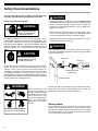
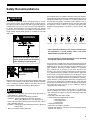
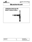
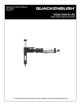
Operation & Service Manual
823200
1/02
158QGDA-15RAB-SU-RS
RIGHT ANGLE DRILLS
Houston Operation
7007 Pinemont
Houston, TX 77040
Recoules Operation
Zone industrielle - B.P. 28
Avenue Maurice Chevalier
77831 Ozoir-la-Ferriere Cedex France
1
Safety Recommendations
For your safety and the safety of others, read and understand
the safety recommendations and operating instructions.
Always wear protective equipment:
!
WARNING
Impact resistant eye protection
must be worn while operating
or working near this tool.
For additional information on eye and face protection, refer to
Federal OSHA Regulations, 29 Code of Federal Regulations, Section 1910.133., Eye and Face Protection, and American National
Standards Institute, ANSI Z87.1, Occupational and Educational Eye
and Face Protection. Z87.1 is available from the American National
Standards Institute, Inc., 11 West 42nd Street, New York, N.Y.
10036.
!
CAUTION
Personal hearing protection is
recommended when operating
or working near this tool.
Hearing protection is recommended in high noise areas, 85 dBA or
greater. The operation of other tools and equipment in the area,
reflective surfaces, process noises and resonant structures can
substantially contribute to and increase the noise level in the area.
For additional information on hearing protection, refer to Federal
OSHA Regulations, 29 Code of Federal Regulations, Section 1910.95,
Occupational Noise Exposure, and American National Standards
Institute, ANSI S12.6, Hearing Protectors.
!
WARNING
Follow good machine shop
practices. Rotating shafts and
moving components entangle
and entrap, and may result in
serious injuries. Never wear
long hair, loose-fitting clothes,
gloves, ties, or jewelry when
working with or near a drill of
any type.
Do not wear loose fitting clothes,
long hair, gloves, ties or jewelry.
2
!
CAUTION
• Quackenbush drills are designed to operate on 90psig (6.2 bar)
air pressure. Excessive air pressure can increase the loads and
stresses on tool parts and drills, and may result in breakage. The
installation of a filter-regulator-lubricator in the air supply line is
highly recommended.
• Before removing a tool from service or changing drill bits, make
sure the air line is shut off and drained of air. This will prevent the
tool from operating if the throttle is accidently engaged.
• Cutting tools used with these Quackenbush drill motors are sharp.
Handle them carefully to avoid injury.
!
CAUTION
Before mounting any positive feed drill, check the lock screws in the
tooling fixture and drill bushing. Make sure both are in good condition
and securely tightened.
Lock Screws
Tool Nose
Standard Threaded
Drill Bushing
Tooling Fixture
Positive feed drills can exert high torques and high thrust loads. If
failure of the lock screws or drill bushing occurs, the drill may
suddenly spin and back away from the drill fixture.
Warning Labels
The warning labels found on these tools are essential parts of this
product. Labels should not be removed. Labels should be checked
periodically for legibility. Replace warning labels when missing or
when the information can no longer be read. Replacement labels
can be ordered from the manufacturer.
Safety Recommendations
!
CAUTION
The spindle on right angle positive feed drills retracts at a much
faster rate than it feeds. Care should be taken to avoid entrapment.
Nose pieces usually used with these drills are generally slotted for
visibility and access to chuck, cutter, and retract stop adjustments.
A spindle guard should be used when operating tool. Spindle
guards in one inch increments are available to accommodate any
length spindle. Slotted spindle guards are available for tools with
fluid swivels.
Some individuals are susceptible to disorders of the hands and arms
when exposed to tasks which involve repetitive work motions. Those
individuals predisposed to vasculatory or circulatory problems may
be particularly susceptible. Cumulative trauma disorders such as
carpal tunnel syndrome and tendinitis may be caused or aggravated
by repetitious, forceful exertions of the hands and arms. These
disorders develop gradually over periods of weeks, months, and
years.
Avoid
OK
Avoid
Avoid
OK
Avoid
Neutral
Ulnar Deviation
WARNING
!
Extension
Neutral
Flexion
Radial Deviation
• Tasks should be performed in such a manner that the wrists
are maintained in a neutral position, which is not flexed,
hyperextended, or turned side to side.
Keep hands and fingers away from
slot in spindle guard and nose piece
• Stressful postures should be avoided and can be controlled
through tool selection and work location.
when handling or operating tool.
!
WARNING
Wear respirator where
necessary.
Drilling or other use of this tool may produce hazardous fumes and/
or dust. To avoid adverse health effects utilize adequate ventilation
and/or a respirator. Read the material safety data sheet for any
cutting fluids or materials involved in the drilling process.
!
WARNING
• Most dusts are combustible. See material safety data sheets for
combustibility of a specific dust.
• Non ferrous metal dusts are particularly haxardous.
Examples: Aluminum, Magnesium, Titanium, Zirconium
(Never collect Magnesium in a dry dust collector)
• Never collect spark generating material in the same dust collector
with combustible material.
Examples: Collecting both Steel and Aluminum dust or Steel and
Titanium dust.
• Never use flamable finishing lubricants.
Any tool operator should be aware of the following warning signs and
symptoms so that a problem can be addressed before it becomes a
debilitating injury. Any user suffering prolonged symptoms of tingling, numbness, blanching of fingers, clumsiness or weakened
grip, nocturnal pain in the hand, or any other disorder of the
shoulders, arms, wrists, or fingers is advised to consult a physician.
If it is determined that the symptoms are job related or aggravated
by movements and postures dictated by the job design, it may be
necessary for the employer to take steps to prevent further occurrences. These steps might include, but are not limited to, repositioning the workpiece or redesigning the workstation, reassigning workers to other jobs, rotating jobs, changing work pace, and/or changing
the type of tool used to minimize stress on the operator. Some tasks
may require more than one type of tool to obtain the optimum
operator/tool/task relationship.
The following recommendations will help reduce or moderate the
effects of repetitive work motions. The operator of any drill should:
• Use a minimum hand grip force consistent with proper control and
safe operation
• Keep body and hands warm and dry
• Avoid anything that inhibits blood circulation
— Smoking Tobacco
— Cold Temperatures
— Certain Drugs
• Avoid awkward postures
• Keep wrists as straight as possible
• Interrupt work activities, or rotate jobs to provide periods free from
repetitive work motions.
3
OPERATING & SERVICE INSTRUCTIONS
The tool is designed to operate on 90 psig air pressure using
a 1/2 inch l.D. hose up to 8 feet in length. If additional length
is required, a 5/8 inch l.D. or larger hose should be connected to the 1/2 inch hose.
NOTE: Safety Labels can be ordered using part no. 202691.
The tool is started by turning the trigger 613697 to the on
position.
The feed cycle is started by pushing the retract lever 622973
down. The spindle may be controlled by the Automatic Stop
or it may be manually retracted at any point by pulling the
retract lever up. Rapid retraction of the spindle takes place
while the spindle continues to rotate.
NOTE: The Gear Stop 622985 can be adjusted by turning
the two 1/8" hex set screws 867502 on either side of the
angle head.
Before installing or removing a cutting tool, or accessory, be
sure the tool is disconnected from the air supply. If the air
supply line has a valve, shut the valve off and bleed off the
air in the line.
POWER UNIT
To remove the motor unit from the motor housing, invert the
tool in the vise. Loosen the handle nut 613283 and remove
the handle. The complete motor unit may now be slipped out
through the rear of the motor housing. Unscrew the governor ( Left Hand Threads) and remove the rear bearing plate
613241 from the shaft. Remove the rotor shaft retainer
843618 and using a soft mallet tap the rotor shaft out of the
front rotor bearing 613248. This will allow the front bearing
plate 613273, the cylinder 613225, rotor blades 613236,
and the rotor 613234, to be removed. Remove the two (2)
keys 863365, from the rotor shaft 624294, and clamp it in the
vise with the governor up. To remove the front rotor bearing
from the front bearing plate for inspection, the rotor bearing
retainer 613294, (Left Hand Treads) must be unscrewed
first.
DISASSEMBLY AND REASSEMBLY DRILL HEAD
Unscrew (Left Hand Threads) and remove the drill head
from the power unit To disassemble the drill head slip the
spacer 617149 out of the rear of the head. This will allow the
ball bearing No 847095 and bevel gear 622947 to be
removed.
LUBRICATlON
An automatic in-line filter-regulator-lubricator is recommended as it increases tool life and keeps the tool in
sustained operation. The in-line lubricator should be regularly checked and filled with a good grade of 10W machine
oil. Proper adjustment of the in-line lubricator is performed
by placing a sheet of paper next to the exhaust ports and
holding the throttle open approximately 30 seconds. The
lubricator is properly set when a light stain of oil collects on
the paper. Excessive amounts of oil should be avoided.
STORAGE
In the event that it becomes necessary to store the tool for
an extended period of time (overnight, weekend, etc.), it
should receive a generous amount of lubrication at that time
and again when returned to service. The tool should be
stored in a clean and dry environment.
GENERAL
Clamp the tool lightly on the flats of the motor housing in a
soft jawed vise and unscrew the drill head from the power
unit.
4
Unscrew the four (4) retract body screws 863337 and
remove the retract body 624094 and attached components.
Loosen the stop collar screw 617785 and unscrew the stop
collars 617962 (Left Hand Threads). Removing the nose
adapter (Left Hand Threads) will allow the spindle and
attached parts to be removed from the drill head.
Unscrew the four (4) cover screws and remove the cover
625092 and attached parts. The drill head is reassembled
in the reverse order of disassembly. All parts should be
carefully inspected for evidence of wear. Damaged or worn
parts should be replaced where necessary. As all of the
various gears and bearings are being assembled they
should be coated with a generous amount of LUBRIPLATE
#907 GREASE. When installing the bearing 617168, the
ball loading notches should be facing up.
During reassembly be sure that the rotor shaft 624294 is
engaged in the drill head.
RIGHT ANGLE HEAD
5
PART LISTS — DRILL HEAD
PART NO.
613828
614574
614575
617149
617166
617168
617785
617962
617980
617993
619016
622400
622401
622946
622947
622948
622949
622950
622952
622954
622973
622976
622978
622980
622984
622985
622986
623000
623001
623002
623003
624094
624295
624351
624355
625092
834228
842161
844111
844247
844265
844306
844787
847095
847430
847609
863337
863463
865576
867502
NAME OF PART
QUANITY
Name Plate
Idler Gear Spacer (Long)
Idler Gear Spacer (Short)
Spacer
Flat Head Screw (6/32" x 5/8")
Feed Gear Ball Bearing
Stop Collar Set Screw
Stop Collar
Ball Bearing
Spring
Retainer Ring
Ball Bearing
Nose Adapter
Driven Bevel Gear
Driving Bevel Gear
Idler Gear
Differential Drive Gear
Spindle Drive Gear
Pinion & Shaft
Ball Plunger
Retract Lever
Drive Gear Retainer Screw
Dowel Pin
Idler Gear Shaft
Clutch Roller
Gear Stop
Housing
.0005" Differential Feed Gear (34T)
.0005" Spindle Feed Gear (37T)
.001" Spindle Feed Gear (43T)
.001" Differential Feed Gear (40T)
Retract Body
Angle Head Adapter
Fluid Spindle Guard Shims (.010")
Spindle Guard Cap**
Cover
Drive Screw
Steel Ball (3/16")
Lever Pin
Roller Spring
Steel Ball (1/8")
"O"-Ring 5/16" x 7/16"
Roll Pin
Bevel Gear Ball Bearing
Drive Gear Needle Bearing
Pinion Shaft Ball Bearing
Socket Head Cap Screw
Flat Head Screw (6/32" x 3/8")
Thrust Race
Set Screw
1
1
1
1
2
1
2
2
1
1
2
1
1
1
1
1
1
1
1
2
1
1
2
1
4
1
1
1
1
1
1
1
1
1
4
1
2
1
1
2
1
1
1
2
1
1
4
2
1
2
**Included with Spindle Guards
Drill Head Assemblies
Feed
.0005"
.001"
6
Code No.
631242
631240
MOTOR UNIT
PART NO.
613102
613109
613110
613162
613225
613234
613236
613241
613242
613248
613253
613254
613273
613275
613282
613283
613294
613367
613368
613372
NAME OF PART
Hose Adaptor
Gasket
Screen
Cylinder Pin
Cylinder
Rotor
Rotor Blade
Rear Bearing Plate
Sleeve
Front Rotor Bearing
Throttle Valve Washer
Throttle Valve (Incl. 812165)
Front Bearing Plate
Motor Housing
Clamp Ring
Handle Nut
Bearing Retainer Nut
Retainer Ring
Governor Spring
Governor Weight
QTY.
PART NO.
1
1
1
1
1
1
4
1
1
1
1
1
1
1
1
1
1
1
1
2
613374
613375
613376
613377
613378
613688
613697
615391
615466
615467
617397
619987
624294
812165
812231
843618
844111
844265
844308
847511
863365
NAME OF PART
Governor Weight Pin
Governor Spider
Governor Valve
Governor Spring Cap
Governor Spring Retainer
Throttle Valve Bushing
Trigger
Exhaust Deflector
Wire Screen (Inner)
Wire Screen (Outer)
Backhead (Incl. 613688, 619987)
Governor Jet
Rotor Shaft
Stop Pin
Retainer Ring
Retainer Ring
Trigger Pin
Steel Ball (1/8")
"O" Ring 3/8" X 9/16"
Rear Rotor Bearing
Rotor Shaft Key
QTY.
2
1
1
1
1
1
1
1
1
1
1
1
1
1
1
1
1
2
2
1
2
The complete backhead can be purchased as subassembly using the following part number: 611185
7
CooperTools
7007 Pinemont
Houston, Texas 77040
Phone: (713) 462-4521
Fax: (713) 460-7008
www.cooperindustries.com
8